EP2749810A1 - Beleuchtungskörper für fahrzeug - Google Patents
Beleuchtungskörper für fahrzeug Download PDFInfo
- Publication number
- EP2749810A1 EP2749810A1 EP12825197.2A EP12825197A EP2749810A1 EP 2749810 A1 EP2749810 A1 EP 2749810A1 EP 12825197 A EP12825197 A EP 12825197A EP 2749810 A1 EP2749810 A1 EP 2749810A1
- Authority
- EP
- European Patent Office
- Prior art keywords
- surface areas
- lens
- front surface
- light
- rear surface
- Prior art date
- Legal status (The legal status is an assumption and is not a legal conclusion. Google has not performed a legal analysis and makes no representation as to the accuracy of the status listed.)
- Withdrawn
Links
- 238000005286 illumination Methods 0.000 title 1
- 230000003287 optical effect Effects 0.000 description 33
- 230000008033 biological extinction Effects 0.000 description 3
- 239000000470 constituent Substances 0.000 description 2
- 230000003245 working effect Effects 0.000 description 2
- 230000004075 alteration Effects 0.000 description 1
- 239000013078 crystal Substances 0.000 description 1
- 238000006073 displacement reaction Methods 0.000 description 1
- 230000009189 diving Effects 0.000 description 1
- 238000012986 modification Methods 0.000 description 1
- 230000004048 modification Effects 0.000 description 1
Images


Classifications
-
- F—MECHANICAL ENGINEERING; LIGHTING; HEATING; WEAPONS; BLASTING
- F21—LIGHTING
- F21S—NON-PORTABLE LIGHTING DEVICES; SYSTEMS THEREOF; VEHICLE LIGHTING DEVICES SPECIALLY ADAPTED FOR VEHICLE EXTERIORS
- F21S41/00—Illuminating devices specially adapted for vehicle exteriors, e.g. headlamps
- F21S41/10—Illuminating devices specially adapted for vehicle exteriors, e.g. headlamps characterised by the light source
- F21S41/14—Illuminating devices specially adapted for vehicle exteriors, e.g. headlamps characterised by the light source characterised by the type of light source
- F21S41/141—Light emitting diodes [LED]
- F21S41/143—Light emitting diodes [LED] the main emission direction of the LED being parallel to the optical axis of the illuminating device
-
- F—MECHANICAL ENGINEERING; LIGHTING; HEATING; WEAPONS; BLASTING
- F21—LIGHTING
- F21S—NON-PORTABLE LIGHTING DEVICES; SYSTEMS THEREOF; VEHICLE LIGHTING DEVICES SPECIALLY ADAPTED FOR VEHICLE EXTERIORS
- F21S41/00—Illuminating devices specially adapted for vehicle exteriors, e.g. headlamps
- F21S41/20—Illuminating devices specially adapted for vehicle exteriors, e.g. headlamps characterised by refractors, transparent cover plates, light guides or filters
- F21S41/25—Projection lenses
- F21S41/255—Lenses with a front view of circular or truncated circular outline
-
- F—MECHANICAL ENGINEERING; LIGHTING; HEATING; WEAPONS; BLASTING
- F21—LIGHTING
- F21S—NON-PORTABLE LIGHTING DEVICES; SYSTEMS THEREOF; VEHICLE LIGHTING DEVICES SPECIALLY ADAPTED FOR VEHICLE EXTERIORS
- F21S41/00—Illuminating devices specially adapted for vehicle exteriors, e.g. headlamps
- F21S41/20—Illuminating devices specially adapted for vehicle exteriors, e.g. headlamps characterised by refractors, transparent cover plates, light guides or filters
- F21S41/25—Projection lenses
- F21S41/265—Composite lenses; Lenses with a patch-like shape
-
- F—MECHANICAL ENGINEERING; LIGHTING; HEATING; WEAPONS; BLASTING
- F21—LIGHTING
- F21S—NON-PORTABLE LIGHTING DEVICES; SYSTEMS THEREOF; VEHICLE LIGHTING DEVICES SPECIALLY ADAPTED FOR VEHICLE EXTERIORS
- F21S41/00—Illuminating devices specially adapted for vehicle exteriors, e.g. headlamps
- F21S41/20—Illuminating devices specially adapted for vehicle exteriors, e.g. headlamps characterised by refractors, transparent cover plates, light guides or filters
- F21S41/25—Projection lenses
- F21S41/275—Lens surfaces, e.g. coatings or surface structures
-
- F—MECHANICAL ENGINEERING; LIGHTING; HEATING; WEAPONS; BLASTING
- F21—LIGHTING
- F21W—INDEXING SCHEME ASSOCIATED WITH SUBCLASSES F21K, F21L, F21S and F21V, RELATING TO USES OR APPLICATIONS OF LIGHTING DEVICES OR SYSTEMS
- F21W2102/00—Exterior vehicle lighting devices for illuminating purposes
-
- F—MECHANICAL ENGINEERING; LIGHTING; HEATING; WEAPONS; BLASTING
- F21—LIGHTING
- F21W—INDEXING SCHEME ASSOCIATED WITH SUBCLASSES F21K, F21L, F21S and F21V, RELATING TO USES OR APPLICATIONS OF LIGHTING DEVICES OR SYSTEMS
- F21W2102/00—Exterior vehicle lighting devices for illuminating purposes
- F21W2102/10—Arrangement or contour of the emitted light
- F21W2102/13—Arrangement or contour of the emitted light for high-beam region or low-beam region
- F21W2102/135—Arrangement or contour of the emitted light for high-beam region or low-beam region the light having cut-off lines, i.e. clear borderlines between emitted regions and dark regions
- F21W2102/155—Arrangement or contour of the emitted light for high-beam region or low-beam region the light having cut-off lines, i.e. clear borderlines between emitted regions and dark regions having inclined and horizontal cutoff lines
Definitions
- the present invention relates to a vehicular lamp configured to form a predetermined lamp light distribution pattern by controlling the deflection of light emitted from a light source by a lens disposed at a front side of the light source.
- Patent Literature 1 and “Patent Literature 2,” there has been known a vehicular lamp which is configured to form a predetermined lamp light distribution pattern by controlling the deflection of light emitted from a light source such as a light emitting element by a lens disposed at a front side of the light source.
- the lens is formed into a planoconvex lens, and the light emitting element is disposed near a rear focal point.
- the lens is described as being formed by connecting in a circumferential direction four lens pieces of the same shape which are each cut into a sector at a predetermined central angle from an elliptic lens having a front convex elliptic surface and a rear concave elliptic surface.
- the front surface thereof is divided into the plurality of front areas by ridge lines, and therefore, it is possible to produce the lens design which is different from a lens design in which a front surface of the lens is formed by a single curved surface.
- the light source of the lamp is a point light source which is disposed at the rear focal point of the lens
- light which is incident on the rear surface of one of the four lens pieces which make up the lens reaches the front surface of the same lens piece.
- the light source has a certain size, and light from positions lying apart from the rear focal point also reaches the lens. Therefore, light which is incident on the rear surface of any one of the four lens pieces does not always reach the front surface of the same lens piece, and as this occurs, part of the light which reaches the front surface of the different lens piece is emitted in a direction which differs from the expected emitting direction from the front surface of the lens piece. Because of this, the control of deflection of light from the light source cannot be performed accurately.
- the invention has been made in view of these situations, and an object thereof is to provide a vehicular lamp configured to form a predetermined lamp light distribution pattern by controlling the deflection of light emitted from a light source by a lens which can provide a novel lens design while ensuring that the deflection of the light emitted from the light source can be controlled accurately by the lens.
- a vehicular lamp of the invention comprises:
- the kind of the "light source” is not particularly limited and also the concrete size and orientation thereof is not limited.
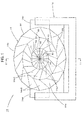
- Fig. 1 is a front view of a vehicular lamp 10 according to an embodiment of the invention
- Fig. 2 is a sectional view taken along the line II-II in Fig. 1
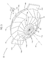
- Fig. 3 is a perspective view showing main constituent elements of the vehicular lamp 10.
- this vehicular lamp 10 includes a light source 12 and a lens 14 which is disposed at a front side of the light source 12, whereby a predetermined lamp light distribution pattern is formed by controlling the deflection of light emitted from the light source 12 by the lens 14.
- This vehicular lamp 10 is used as a lamp unit for a vehicle headlamp in such a state that the vehicular lamp 10 is incorporated in a lamp body or the like, which is not shown, in such a way that an optical axis thereof can be controlled. Additionally, in this vehicular lamp 10, at a stage where the optical axis control has been completed, an optical axis Ax of the lens 14 is set to extend in a direction which is inclined downwards at an angle of the order of 0.5 to 0.6° with respect to a front-to-rear direction of the vehicle.
- the light source 12 is a light emitting chip of a white light emitting diode and has a light emitting surface of a horizontally elongated rectangular shape (for example, a rectangle which is approximately 1 mm wide and 2 mm long). Then, this light source 12 is disposed with the light emitting surface thereof directed in the direction of the front of the lamp and with a predetermined point A, which is positioned at a transverse center of a lower edge 12a thereof, positioned on the optical axis Ax.
- This light source 12 is supported by a lens holder 18 via light source support member 16.
- the lens 14 has a lens shape which approximates to a shape which results from horizontally elongating a planoconvex aspheric lens for which a front surface is convex and a rear surface is plane.
- this lens 14 has a substantially horizontally elongated elliptic shape as its external shape when the lamp is seen from the front thereof, and the shape is set to a shape of twofold rotation symmetry with respect to the optical axis Ax. Then, this lens 14 is supported by the lens holder 18 at a pair of tabs 14d formed at both left- and right-hand side portions of an outer circumferential surface 14c thereof.
- a front surface 14a of this lens 14 is divided into 48 front surface areas 14a1 , 14a2, 14a3 by ridge lines R1 to R5.
- the front surface areas 14a1 are 16 areas which are situated in a central portion of the front surface 14a.
- the individual surface areas 14a1 are triangular areas which are defined by 16 ridge lines R1 which extend radially about the optical axis Ax and ridge lines R4 which extend along a polygon which is inscribed in a horizontally elongated ellipse which is centered at the optical axis Ax, each having a concavely curved surface shape.
- the front surface areas 14a2 are 16 areas which are situated in an annular portion lying on an outer circumferential side of the 16 surface areas 14a1.
- the individual surface areas 14a2 are quadrangular areas which are defined by the ridge lines R4, 16 ridge lines R2 which extend from positions at outer circumferential ends of the ridge lines R1 in directions which are inclined in a clockwise direction from a radial direction with respect to the optical axis Ax, and ridge lines R5 which extend along a polygon which is inscribed in a horizontally elongated ellipse which is centered at the optical axis Ax, each having a concavely curved surface shape.
- the front surface areas 14a3 are 16 areas which are situated in an annular portion lying on an outer circumferential side of the 16 front surface areas 14a2.
- the individual front surface areas 14a3 are quadrangular areas which are defined by the ridge lines R5, 16 ridge lines R3 which extend from positions at outer circumferential ends of the ridge lines R2 in directions which are inclined in a counterclockwise direction from the radial direction with respect to the optical axis Ax, and ridge lines R6 which extend along a polygon which is inscribed in a horizontally elongated ellipse which is centered at the optical axis Ax, each having a concavely curved surface shape.
- the ridge lines R6 constitute a boundary between the 16 front surface areas 14a3 and the outer circumferential surface 14c of the lens 14.
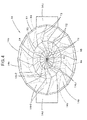
- Fig. 4 is a view resulting when the lens 14 is seen from the rear thereof.
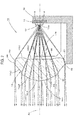
- Figs. 5 , 6 and 7 are a side sectional view, a horizontally sectional view and a front view of the lens 14, respectively, which show an optical operation of the lens 14.
- a rear surface 14b of the lens 14 is divided into 48 rear surface areas 14b1, 14b2, 14b3 via trough lines T1 to T5.
- These 48 rear surface areas 14b1, 14b2, 14b3 are formed so as to be positioned substantially at the rear of the 48 front surface areas 14a1, 14a2, 14a3, respectively.
- the rear surface areas 14b1 are 16 areas which are positioned in a central portion of the rear surface 14b.
- the individual rear surface areas 14b1 are substantially triangular areas which are defined by 16 trough lines T1 which extend radially about the optical axis Ax and trough lines T4 which extend along a polygon which is inscribed in a horizontally elongated ellipse which is centered at the optical axis Ax, each having a convexly curved surface shape.
- the individual trough lines T1 are formed in positions where they are substantially superposed on the individual ridge lines R1, and the trough lines T4 are formed in positions where they are closer to the optical axis Ax than the ridge lines R4.
- the curvature of the convexly curved surfaces which make up the surface shape of the individual rear surface areas 14b1 is set so that light which is emitted from the predetermined point A and then incident on the lens 14 from the rear surface areas 14b1 reaches zones (shaded zones in Fig. 7 ) Z1 on the individual front surface areas 14a1 which corresponds to the individual rear surface areas 14b1 (that is, the front surface areas situated substantially in front of the corresponding rear surface areas), the zones Z1 each lying centrally inwards apart from the ridge lines R1, R4 which define each front surface area 14a1.
- the rear surface areas 14b2 are 16 areas which are situated in an annular portion lying on an outer circumferential side of the 16 rear surface areas 14b1.
- the individual rear surface areas 14b2 are substantially quadrangular areas which are defined by the trough lines T4, 16 trough lines T2 which extend in directions which are inclined in a counterclockwise direction from a radial direction with respect to the optical axis Ax from positions on the trough lines T4 which are slightly offset in the counterclockwise direction from outer circumferential ends of the individual trough lines T1, and trough lines T5 which extend along a substantially polygonal shape which is inscribed in a horizontally elongated ellipse which is centered at the optical axis Ax, each having a convexly curved surface shape.
- the trough lines T5 are formed in positions where they are closer to the optical axis Ax than the ridge lines R5.
- the curvature of the convexly curved surfaces which make up the surface shape of the individual rear surface areas 14b2 is set so that light which is emitted from the predetermined point A and then incident on the lens 14 from the rear surface areas 14b2 reaches zones (shaded zones in Fig. 7 ) Z2 on the individual front surface areas 14a2 which corresponds to the individual rear surface areas 14b2, the zones Z2 each lying centrally inwards apart from the ridge lines R4, R2, R5 which define each front surface area 14a2.
- the rear surface areas 14b3 are 16 areas which are situated in an annular portion lying on an outer circumferential side of the 16 rear surface areas 14b2.
- the individual rear surface areas 14b3 are substantially quadrangular areas which are defined by the trough lines T5, 16 trough lines T3 which extend in directions which are inclined in a clockwise direction from the radial direction with respect to the optical axis Ax from positions on the trough lines T5 which are slightly offset in the clockwise direction from outer circumferential ends of the individual trough lines T2, and ridge lines R7 which extend along a substantially polygonal shape which is inscribed in a horizontally elongated ellipse which is centered at the optical axis Ax, each having a convexly curved surface shape.
- the ridge lines R7 are formed closer to the optical axis Ax than the ridge lines R6.
- the curvature of the convexly curved surfaces which make up the surface shape of the individual rear surface areas 14b3 is set so that light which is emitted from the predetermined point A and then incident on the lens 14 from the rear surface areas 14b3 reaches zones (shaded zones in Fig. 7 ) Z3 on the individual front surface areas 14a3 which corresponds to the individual rear surface areas 14b3, the zones Z3 each lying centrally inwards apart from the ridge lines R5, R3, R6 which define each front surface area 14a3.
- 16 connecting areas 14e are formed between the 16 rear surface areas 14b3 and the outer circumferential surface 14c of the lens 14 at an angle which light from the light source 12 is not incident thereinto.
- the individual front surface areas 14a1, 14a2, 14a3 cause light which is emitted from the predetermined point A and then incident on the lens 14 from the individual rear surface areas 14b1, 14b2, 14b3 to be emitted in a direction which is parallel to the optical axis Ax with respect to a vertical direction.
- the curvatures of the curved surfaces which make up the surface shapes of the individual front surface areas 14a1, 14a2 and 14a3 are set so that the light is emitted as diffuse light which travels substantially parallel to the optical axis Ax at the individual front surface areas 14a1, the light is emitted as diffuse light which travels in directions in which the light travels slight away from the optical axis Ax at the front surface 14a2, and the light is emitted as diffuse light which travels in directions in which the light travels farther away from the optical axis Ax at the front surface areas 14a3.
- the size of the light emitting surface of the light source 12 is not large enough to cause a change in position on the lens from which light from the light source 12 is emitted, in other words, the light emitted from the point B is also emitted from the front surface areas 14a1, 14a2, 14a3 from which the light emitted from the predetermined point A is emitted.
- light emitted from points situated at both left and right edges of the light source 12 is also emitted from the front surface areas 14a1, 14a2, 14a3 from which the light emitted from the predetermined point A is emitted.
- Fig. 8 is a drawing which shows in a perspective fashion a lamp light distribution pattern PA which is formed on an imaginary vertical screen which is disposed in a position 25 m ahead of the vehicle by light irradiated to the front from the vehicular lamp 10.
- This lamp light distribution pattern is a light distribution pattern which is formed as part of a low-beam light distribution pattern PL indicated by a chain double-dashed line in Fig. 8 .
- This low-beam light distribution pattern PL is a low-beam light distribution pattern for a left-hand side traffic which is formed by lights irradiated by the vehicular lamp 10 and the other vehicular lamp which is not shown and has cutoff lines CL1, CL2 which differ in level on left- and right-hand sides along an upper edge thereof.
- cutoff lines CL1, CL2 extend horizontally in different levels on left-and right-hand sides of a line V-V as a boundary which passes vertically through an extinction point ahead of the lamp.
- An on-coming vehicle lane portion which lies on the right-hand side of the line V-V is formed as a lower cutoff line CL1
- a subject vehicle lane portion which lies on the left-hand side of the line V-V is formed as an upper cutoff line CL2 which lies on an upper level than the lower cutoff line CL1 via an inclined portion.
- an elbow point E which constitutes a point of intersection between the lower cutoff line CL1 and the line V-V is situated on the order of 0.5 to 0.6° below the extinction point.
- the lamp light distribution pattern PA is formed as a combined light distribution pattern of 48 light distribution patterns which are formed by a combination of the individual rear surface areas 14b1, 14b2, 14b3 and the individual front surface areas 14a1, 14a2, 14a3.
- This lamp light distribution pattern PA is formed as a horizontally elongated light distribution pattern which is centered at the line V-V by diffusing light emitted from the light source 12 having the horizontally elongated light emitting surface slightly leftwards and rightwards by the lens 14, and has a horizontal cutoff line CLa at an upper end portion thereof.
- the lower edge 12a of the light source 12 extends horizontally, and the predetermined point A which is the transverse center of the lower edge 12a is situated on the optical axis Ax.
- the horizontal cutoff line CLa is situated on the order of 0.5 to 0.6° below the extinction point, and this is because the optical axis Ax extends in a direction which is inclined downwards at an angle of the order of 0.5 to 0.6° with respect to the front-to-rear direction of the vehicle.
- This lamp light distribution pattern PA contributes to an increase in brightness in an area which is centered at the elbow point E in the low-beam light distribution pattern PL and which lie near and below the cutoff lines CL1, CL2.
- the vehicular lamp 10 is configured to form the lamp light distribution pattern PA by controlling the deflection of light emitted from the light source 12 by the lens 14 which is disposed ahead of the light source 12.
- the front surface 14a of the lens 14 is divided into the 48 front surface areas 14a1, 14a2, 14a3 via the ridge lines R1 to R5, while the rear surface 14b thereof is divided into the 48 rear surface areas 14b1, 14b2, 14b3 via the trough lines T1 to T5, and therefore, the following working effect can be obtained.
- a lens design can be produced which is different from a design produced when the front surface 14a is formed by a single curved surface.
- the rear surface 14b of the lens 14 is divided into the 48 rear surface areas 14b1, 14b2, 14b3 which are the same in number as the 48 front surface front surface areas 14a1, 14a2, 14a3, a crystal touch can be imparted to the lens 14, thereby making it possible to enhance the novelty of the lens design.
- the individual rear surface areas 14b1, 14b2, 14b3 are formed so as to have the surface shapes which are set so that the light which is emitted from the predetermined point A situated on the light source 12 and then incident on the lens 14 from the rear surface areas 14b1, 14b2, 14b3 is caused to reach the zones Z1 to Z3 which lie centrally inwards apart from the ridge lines R1 to R6 on the individual front surface areas 14a1, 14a2, 14a3 which correspond, respectively to the rear surface areas 14b1, 14b2, 14b3.
- the difference between the incidence angle at which the light from those position is incident on the lens 14 and the incidence angle at which the light emitted from the predetermined point A is incident on the lens 14 is set to the smaller value than the angles which correspond to spaces defined between the ridge lines R1 to R6 and the zones Z1 to Z3 which lie centrally inwards apart from those ridge lines.
- the individual front surface areas 14a1, 14a2, 14a3 are formed so as to have the surface shapes which are set so that the light which is emitted from the predetermined point A and then reaches the front surface areas 14a1, 14a2, 14a3 via the corresponding rear surface areas 14b1, 14b2, 14b3 is emitted individually in the predetermined directions from the front surface areas 14a1, 14a2, 14a3.
- the novel design can be imparted to the lens 14 while enabling the deflection of light emitted from the light source 12 to be controlled accurately by the lens 14.
- the novelty of the lens design can be enhanced since the front surface 14a of the lens 14 is divided into the 48 rear surface areas 14b1, 14b2, 14b3 by the 16 ridge lines R1, R2, R3 which extend in the radial direction in a zigzag fashion and the two ridge lines R4, R5 which extend concentrically with the ridge line R6 which constitutes the boundary with the outer circumferential surface 14c of the lens 14.
- the predetermined point A is described as being situated on the lower edge 12a of the light source 12, a configuration can be adopted in which the predetermined point A is situated in any other position on the light source 12 or a position out of the light source 12.
- the front surface 14a of the lens 14 is divided into the 48 front surface areas 14a1, 14a2, 14a3, a configuration can, of course, be adopted in which the front surface 14a is divided into any other numbers than this number, and a configuration can also be adopted in which the front surface 14a is divided into front surface areas having different shapes from those of the 48 front surface areas 14a1, 14a2, 14a3.
- the vehicular lamp 10 is described as being configured to control the deflection of light emitted from the light source 12 by the lens 14, the vehicular lamp 10 can be configured as a so-called projector-type vehicular lamp in which light from a light source 12 which is disposed further rearwards than the predetermined point A is reflected towards a lens 14 by a reflector, not shown.
- Fig. 9 is a similar drawing to Fig. 3 , which shows a vehicular lamp 110 according a modified example of the embodiment above.
- a basic configuration of the vehicular lamp 110 according to this modified example is similar to that of the embodiment described above, the configuration of a lens 114 is partially different from that of the embodiment.
- 16 front surface areas 114a3 which are similar to the 16 front surface areas 14a3 of the embodiment are formed as quadrangular areas which are defined by ridge lines R5 and 16 ridge lines R3 and ridge lines R6 in a circumferentially outermost annular portion on a front surface 114a thereof
- a portion of the front surface 114a which lies radially inwards of the circumferentially outermost annular portion is not formed as the 16 front surface areas 14a1 and the 16 front surface areas 14a2 of the embodiment above but is formed as a single horizontally elongated elliptic surface area 114a0.
- 16 rear surface areas which are similar to the 16 rear surface areas 14b3 of the embodiment above are formed as substantially quadrangular shapes in a circumferentially outermost portion.
- a portion of the rear surface which lies radially inwards of the circumferentially outermost annular portion is not formed as the 16 rear surfaces areas 14b1 and the 16 rear surface areas 14b2 of the embodiment above but is formed as a flat area.
- the novel design can be imparted to the lens 114 while enabling the deflection of light emitted from the light source 12 to be controlled accurately by the lens 114.
- numeric values shown as the specifications of the vehicular lamps in the embodiment and its modified example are only the examples, and hence, these numeric values may, of course, be set to different values as required.
Landscapes
- Engineering & Computer Science (AREA)
- General Engineering & Computer Science (AREA)
- Physics & Mathematics (AREA)
- Microelectronics & Electronic Packaging (AREA)
- Optics & Photonics (AREA)
- Non-Portable Lighting Devices Or Systems Thereof (AREA)
Applications Claiming Priority (2)
| Application Number | Priority Date | Filing Date | Title |
|---|---|---|---|
| JP2011183484A JP5731932B2 (ja) | 2011-08-25 | 2011-08-25 | 車両用照明灯具 |
| PCT/JP2012/069737 WO2013027555A1 (ja) | 2011-08-25 | 2012-08-02 | 車両用照明灯具 |
Publications (2)
| Publication Number | Publication Date |
|---|---|
| EP2749810A1 true EP2749810A1 (de) | 2014-07-02 |
| EP2749810A4 EP2749810A4 (de) | 2015-11-25 |
Family
ID=47746306
Family Applications (1)
| Application Number | Title | Priority Date | Filing Date |
|---|---|---|---|
| EP12825197.2A Withdrawn EP2749810A4 (de) | 2011-08-25 | 2012-08-02 | Beleuchtungskörper für fahrzeug |
Country Status (5)
| Country | Link |
|---|---|
| US (1) | US9297508B2 (de) |
| EP (1) | EP2749810A4 (de) |
| JP (1) | JP5731932B2 (de) |
| CN (1) | CN103765083B (de) |
| WO (1) | WO2013027555A1 (de) |
Cited By (1)
| Publication number | Priority date | Publication date | Assignee | Title |
|---|---|---|---|---|
| EP3141804A1 (de) * | 2015-09-14 | 2017-03-15 | Valeo Vision | Beleuchtungsmodul für kraftfahrzeugscheinwerfer, und entsprechender scheinwerfer |
Families Citing this family (13)
| Publication number | Priority date | Publication date | Assignee | Title |
|---|---|---|---|---|
| FR2986621B1 (fr) * | 2012-01-12 | 2015-01-23 | Valeo Vision | Lentille pour module optique de vehicule automobile |
| WO2014208655A1 (ja) * | 2013-06-26 | 2014-12-31 | 市光工業株式会社 | 車両用灯具 |
| KR20150018288A (ko) * | 2013-08-09 | 2015-02-23 | 현대모비스 주식회사 | 차량용 램프 및 이를 포함하는 차량 |
| JP6322931B2 (ja) * | 2013-08-29 | 2018-05-16 | 市光工業株式会社 | 車両用灯具 |
| JP2017519361A (ja) * | 2014-05-30 | 2017-07-13 | コーニンクレッカ フィリップス エヌ ヴェKoninklijke Philips N.V. | 自動車照明アプリケーションのための光学レンズパッケージ |
| DE102015105613B4 (de) * | 2015-04-13 | 2023-08-31 | Carl Zeiss Industrielle Messtechnik Gmbh | Auflicht-Beleuchtung für variablen Arbeitsabstand |
| JP6600987B2 (ja) * | 2015-05-21 | 2019-11-06 | 市光工業株式会社 | 車両用灯具 |
| CN106369521A (zh) * | 2016-09-30 | 2017-02-01 | 马瑞利汽车零部件(芜湖)有限公司 | 使用透镜实现近光的汽车前照灯光学系统 |
| CN107036029A (zh) * | 2017-05-03 | 2017-08-11 | 中山市富同晟科技有限公司 | 一种复杂光学系统led汽车前照灯 |
| CN109469884A (zh) * | 2017-09-08 | 2019-03-15 | 法雷奥照明公司 | 用于发光装置的配光元件以及发光装置 |
| CN110094685B (zh) * | 2019-06-12 | 2024-04-26 | 佛山市升阳光学科技有限公司 | 一种具有多种工作状态的照明装置 |
| CN114719222B (zh) * | 2021-01-06 | 2024-06-25 | 华域视觉科技(上海)有限公司 | 透镜组件、车灯模组、车灯和车辆 |
| JP7571553B2 (ja) | 2021-01-13 | 2024-10-23 | 市光工業株式会社 | 車両用灯具のレンズ、車両用灯具、車両用前照灯装置 |
Family Cites Families (20)
| Publication number | Priority date | Publication date | Assignee | Title |
|---|---|---|---|---|
| US4654761A (en) * | 1986-02-28 | 1987-03-31 | General Motors Corporation | Periscopic vehicle lamp lens and lens arrangement including same |
| US4703405A (en) * | 1986-07-17 | 1987-10-27 | Ian Lewin | Glare reducing lens |
| US5676453A (en) * | 1992-04-16 | 1997-10-14 | Tir Technologies, Inc. | Collimating TIR lens devices employing fluorescent light sources |
| US5404869A (en) * | 1992-04-16 | 1995-04-11 | Tir Technologies, Inc. | Faceted totally internally reflecting lens with individually curved faces on facets |
| FR2727742A1 (fr) * | 1994-12-01 | 1996-06-07 | Valeo Vision | Feu de signalisation pour vehicule automobile, notamment du type feu stop sureleve |
| US5801889A (en) * | 1995-08-16 | 1998-09-01 | Eastman Kodak Company | Technique to eliminate scattered light in diffractive optical elements |
| JP3331581B2 (ja) * | 1995-12-22 | 2002-10-07 | 市光工業株式会社 | 車両用灯具 |
| FR2743405B1 (fr) * | 1996-01-10 | 1998-04-03 | Valeo Vision | Feu de signalisation a ecran intermediaire de traitement optique et de style, et procede de fabrication de l'ecran intermediaire |
| DE19635942A1 (de) * | 1996-09-05 | 1998-03-12 | Vitaly Dr Lissotschenko | Optisches Strahlformungssystem |
| DE69803297T2 (de) * | 1997-08-12 | 2002-08-22 | Breault Res Organization Inc | Doppelreflektierende linse |
| DE102004008296A1 (de) * | 2004-02-20 | 2005-09-08 | Daimlerchrysler Ag | Scheinwerferlinse und Scheinwerfer |
| KR100638611B1 (ko) * | 2004-08-12 | 2006-10-26 | 삼성전기주식회사 | 다중 렌즈 발광 다이오드 |
| JP4536483B2 (ja) | 2004-10-27 | 2010-09-01 | 株式会社小糸製作所 | 車両用照明灯具 |
| US7563008B2 (en) * | 2006-03-28 | 2009-07-21 | Visteon Global Technologies, Inc. | LED projector headlamps using single or multi-faceted lenses |
| JP2008140667A (ja) * | 2006-12-01 | 2008-06-19 | Harison Toshiba Lighting Corp | 照明装置 |
| JP4782064B2 (ja) * | 2007-04-10 | 2011-09-28 | 株式会社小糸製作所 | 車両用灯具ユニット |
| JP5044864B2 (ja) | 2007-08-08 | 2012-10-10 | スタンレー電気株式会社 | 灯具用投影レンズ、及び、灯具用投影レンズを用いた灯具 |
| US8136967B2 (en) * | 2008-03-02 | 2012-03-20 | Lumenetix, Inc. | LED optical lens |
| ITPR20080030A1 (it) * | 2008-04-24 | 2009-10-25 | Coemar Spa | Proiettore a luce diffusa |
| FR2943799B1 (fr) * | 2009-03-31 | 2011-09-02 | Valeo Vision Sas | "lentille pour module d'eclairage pour vehicule automobile". |
-
2011
- 2011-08-25 JP JP2011183484A patent/JP5731932B2/ja not_active Expired - Fee Related
-
2012
- 2012-08-02 US US14/240,451 patent/US9297508B2/en not_active Expired - Fee Related
- 2012-08-02 CN CN201280041247.7A patent/CN103765083B/zh active Active
- 2012-08-02 EP EP12825197.2A patent/EP2749810A4/de not_active Withdrawn
- 2012-08-02 WO PCT/JP2012/069737 patent/WO2013027555A1/ja not_active Ceased
Cited By (2)
| Publication number | Priority date | Publication date | Assignee | Title |
|---|---|---|---|---|
| EP3141804A1 (de) * | 2015-09-14 | 2017-03-15 | Valeo Vision | Beleuchtungsmodul für kraftfahrzeugscheinwerfer, und entsprechender scheinwerfer |
| FR3041072A1 (fr) * | 2015-09-14 | 2017-03-17 | Valeo Vision | Module d'eclairage de projecteur de vehicule automobile et projecteur associe |
Also Published As
| Publication number | Publication date |
|---|---|
| CN103765083B (zh) | 2016-04-13 |
| WO2013027555A1 (ja) | 2013-02-28 |
| EP2749810A4 (de) | 2015-11-25 |
| CN103765083A (zh) | 2014-04-30 |
| JP2013045682A (ja) | 2013-03-04 |
| US20140226356A1 (en) | 2014-08-14 |
| JP5731932B2 (ja) | 2015-06-10 |
| US9297508B2 (en) | 2016-03-29 |
Similar Documents
| Publication | Publication Date | Title |
|---|---|---|
| US9297508B2 (en) | Vehicular lamp | |
| CN101285562B (zh) | 车辆用灯具单元 | |
| JP4782064B2 (ja) | 車両用灯具ユニット | |
| US9897274B2 (en) | Vehicle lamp | |
| JP4391870B2 (ja) | 車両用照明灯具 | |
| JP7506809B2 (ja) | 車両用灯具 | |
| JP5233686B2 (ja) | 車両用灯具 | |
| EP2503226B1 (de) | Fahrzeugausleuchtungslampe | |
| US9719651B2 (en) | Vehicle lamp | |
| US10378716B2 (en) | Vehicle lamp | |
| EP3467373B1 (de) | Fahrzeugscheinwerfer und fahrzeug damit | |
| US9249945B2 (en) | Lamp module for vehicle | |
| CN105240759B (zh) | 车用灯具 | |
| JP2015115276A (ja) | 車両用灯具 | |
| US12259104B2 (en) | Automotive lamp | |
| CN103090288A (zh) | 车辆用照明灯具 | |
| CN203823633U (zh) | 车灯结构及其灯杯结构 | |
| JP5692520B2 (ja) | 灯具ユニット | |
| JP2012099228A (ja) | 車両用照明灯具 | |
| EP3857114B1 (de) | Multifokale kollimatorlinse und scheinwerferbaugruppe mit zwei funktionen | |
| JP7569297B2 (ja) | 車両用灯具 | |
| KR20190081639A (ko) | 차량용 광학계 및 이를 이용한 차량용 램프 | |
| JP6635691B2 (ja) | 車両用灯具 | |
| US20060250810A1 (en) | Motor vehicle headlight | |
| JP2025080116A (ja) | 車両用灯具 |
Legal Events
| Date | Code | Title | Description |
|---|---|---|---|
| PUAI | Public reference made under article 153(3) epc to a published international application that has entered the european phase |
Free format text: ORIGINAL CODE: 0009012 |
|
| 17P | Request for examination filed |
Effective date: 20140224 |
|
| AK | Designated contracting states |
Kind code of ref document: A1 Designated state(s): AL AT BE BG CH CY CZ DE DK EE ES FI FR GB GR HR HU IE IS IT LI LT LU LV MC MK MT NL NO PL PT RO RS SE SI SK SM TR |
|
| DAX | Request for extension of the european patent (deleted) | ||
| RA4 | Supplementary search report drawn up and despatched (corrected) |
Effective date: 20151026 |
|
| RIC1 | Information provided on ipc code assigned before grant |
Ipc: F21W 101/10 20060101ALI20151020BHEP Ipc: F21Y 101/02 20060101ALN20151020BHEP Ipc: F21S 8/10 20060101AFI20151020BHEP Ipc: F21V 5/04 20060101ALI20151020BHEP |
|
| STAA | Information on the status of an ep patent application or granted ep patent |
Free format text: STATUS: THE APPLICATION HAS BEEN WITHDRAWN |
|
| 18W | Application withdrawn |
Effective date: 20170626 |