EP2750732B1 - Blutbehandlungsvorrichtung - Google Patents
Blutbehandlungsvorrichtung Download PDFInfo
- Publication number
- EP2750732B1 EP2750732B1 EP12755797.3A EP12755797A EP2750732B1 EP 2750732 B1 EP2750732 B1 EP 2750732B1 EP 12755797 A EP12755797 A EP 12755797A EP 2750732 B1 EP2750732 B1 EP 2750732B1
- Authority
- EP
- European Patent Office
- Prior art keywords
- flow resistance
- determined
- extracorporeal blood
- flow
- extracorporeal
- Prior art date
- Legal status (The legal status is an assumption and is not a legal conclusion. Google has not performed a legal analysis and makes no representation as to the accuracy of the status listed.)
- Active
Links
Images



Classifications
-
- A—HUMAN NECESSITIES
- A61—MEDICAL OR VETERINARY SCIENCE; HYGIENE
- A61M—DEVICES FOR INTRODUCING MEDIA INTO, OR ONTO, THE BODY; DEVICES FOR TRANSDUCING BODY MEDIA OR FOR TAKING MEDIA FROM THE BODY; DEVICES FOR PRODUCING OR ENDING SLEEP OR STUPOR
- A61M1/00—Suction or pumping devices for medical purposes; Devices for carrying-off, for treatment of, or for carrying-over, body-liquids; Drainage systems
- A61M1/14—Dialysis systems; Artificial kidneys; Blood oxygenators ; Reciprocating systems for treatment of body fluids, e.g. single needle systems for hemofiltration or pheresis
- A61M1/16—Dialysis systems; Artificial kidneys; Blood oxygenators ; Reciprocating systems for treatment of body fluids, e.g. single needle systems for hemofiltration or pheresis with membranes
-
- A—HUMAN NECESSITIES
- A61—MEDICAL OR VETERINARY SCIENCE; HYGIENE
- A61M—DEVICES FOR INTRODUCING MEDIA INTO, OR ONTO, THE BODY; DEVICES FOR TRANSDUCING BODY MEDIA OR FOR TAKING MEDIA FROM THE BODY; DEVICES FOR PRODUCING OR ENDING SLEEP OR STUPOR
- A61M1/00—Suction or pumping devices for medical purposes; Devices for carrying-off, for treatment of, or for carrying-over, body-liquids; Drainage systems
- A61M1/14—Dialysis systems; Artificial kidneys; Blood oxygenators ; Reciprocating systems for treatment of body fluids, e.g. single needle systems for hemofiltration or pheresis
- A61M1/16—Dialysis systems; Artificial kidneys; Blood oxygenators ; Reciprocating systems for treatment of body fluids, e.g. single needle systems for hemofiltration or pheresis with membranes
- A61M1/1601—Control or regulation
-
- A—HUMAN NECESSITIES
- A61—MEDICAL OR VETERINARY SCIENCE; HYGIENE
- A61M—DEVICES FOR INTRODUCING MEDIA INTO, OR ONTO, THE BODY; DEVICES FOR TRANSDUCING BODY MEDIA OR FOR TAKING MEDIA FROM THE BODY; DEVICES FOR PRODUCING OR ENDING SLEEP OR STUPOR
- A61M1/00—Suction or pumping devices for medical purposes; Devices for carrying-off, for treatment of, or for carrying-over, body-liquids; Drainage systems
- A61M1/14—Dialysis systems; Artificial kidneys; Blood oxygenators ; Reciprocating systems for treatment of body fluids, e.g. single needle systems for hemofiltration or pheresis
- A61M1/16—Dialysis systems; Artificial kidneys; Blood oxygenators ; Reciprocating systems for treatment of body fluids, e.g. single needle systems for hemofiltration or pheresis with membranes
- A61M1/1601—Control or regulation
- A61M1/1615—Control or regulation using measurements made at different flow rates
-
- A—HUMAN NECESSITIES
- A61—MEDICAL OR VETERINARY SCIENCE; HYGIENE
- A61M—DEVICES FOR INTRODUCING MEDIA INTO, OR ONTO, THE BODY; DEVICES FOR TRANSDUCING BODY MEDIA OR FOR TAKING MEDIA FROM THE BODY; DEVICES FOR PRODUCING OR ENDING SLEEP OR STUPOR
- A61M1/00—Suction or pumping devices for medical purposes; Devices for carrying-off, for treatment of, or for carrying-over, body-liquids; Drainage systems
- A61M1/36—Other treatment of blood in a by-pass of the natural circulatory system, e.g. temperature adaptation, irradiation ; Extra-corporeal blood circuits
- A61M1/3621—Extra-corporeal blood circuits
-
- A—HUMAN NECESSITIES
- A61—MEDICAL OR VETERINARY SCIENCE; HYGIENE
- A61M—DEVICES FOR INTRODUCING MEDIA INTO, OR ONTO, THE BODY; DEVICES FOR TRANSDUCING BODY MEDIA OR FOR TAKING MEDIA FROM THE BODY; DEVICES FOR PRODUCING OR ENDING SLEEP OR STUPOR
- A61M1/00—Suction or pumping devices for medical purposes; Devices for carrying-off, for treatment of, or for carrying-over, body-liquids; Drainage systems
- A61M1/36—Other treatment of blood in a by-pass of the natural circulatory system, e.g. temperature adaptation, irradiation ; Extra-corporeal blood circuits
- A61M1/3621—Extra-corporeal blood circuits
- A61M1/367—Circuit parts not covered by the preceding subgroups of group A61M1/3621
-
- A—HUMAN NECESSITIES
- A61—MEDICAL OR VETERINARY SCIENCE; HYGIENE
- A61M—DEVICES FOR INTRODUCING MEDIA INTO, OR ONTO, THE BODY; DEVICES FOR TRANSDUCING BODY MEDIA OR FOR TAKING MEDIA FROM THE BODY; DEVICES FOR PRODUCING OR ENDING SLEEP OR STUPOR
- A61M60/00—Blood pumps; Devices for mechanical circulatory actuation; Balloon pumps for circulatory assistance
- A61M60/10—Location thereof with respect to the patient's body
- A61M60/104—Extracorporeal pumps, i.e. the blood being pumped outside the patient's body
- A61M60/109—Extracorporeal pumps, i.e. the blood being pumped outside the patient's body incorporated within extracorporeal blood circuits or systems
- A61M60/113—Extracorporeal pumps, i.e. the blood being pumped outside the patient's body incorporated within extracorporeal blood circuits or systems in other functional devices, e.g. dialysers or heart-lung machines
-
- A—HUMAN NECESSITIES
- A61—MEDICAL OR VETERINARY SCIENCE; HYGIENE
- A61M—DEVICES FOR INTRODUCING MEDIA INTO, OR ONTO, THE BODY; DEVICES FOR TRANSDUCING BODY MEDIA OR FOR TAKING MEDIA FROM THE BODY; DEVICES FOR PRODUCING OR ENDING SLEEP OR STUPOR
- A61M60/00—Blood pumps; Devices for mechanical circulatory actuation; Balloon pumps for circulatory assistance
- A61M60/20—Type thereof
- A61M60/205—Non-positive displacement blood pumps
- A61M60/216—Non-positive displacement blood pumps including a rotating member acting on the blood, e.g. impeller
- A61M60/226—Non-positive displacement blood pumps including a rotating member acting on the blood, e.g. impeller the blood flow through the rotating member having mainly radial components
- A61M60/232—Centrifugal pumps
-
- A—HUMAN NECESSITIES
- A61—MEDICAL OR VETERINARY SCIENCE; HYGIENE
- A61M—DEVICES FOR INTRODUCING MEDIA INTO, OR ONTO, THE BODY; DEVICES FOR TRANSDUCING BODY MEDIA OR FOR TAKING MEDIA FROM THE BODY; DEVICES FOR PRODUCING OR ENDING SLEEP OR STUPOR
- A61M60/00—Blood pumps; Devices for mechanical circulatory actuation; Balloon pumps for circulatory assistance
- A61M60/30—Medical purposes thereof other than the enhancement of the cardiac output
- A61M60/36—Medical purposes thereof other than the enhancement of the cardiac output for specific blood treatment; for specific therapy
- A61M60/37—Haemodialysis, haemofiltration or diafiltration
-
- A—HUMAN NECESSITIES
- A61—MEDICAL OR VETERINARY SCIENCE; HYGIENE
- A61M—DEVICES FOR INTRODUCING MEDIA INTO, OR ONTO, THE BODY; DEVICES FOR TRANSDUCING BODY MEDIA OR FOR TAKING MEDIA FROM THE BODY; DEVICES FOR PRODUCING OR ENDING SLEEP OR STUPOR
- A61M60/00—Blood pumps; Devices for mechanical circulatory actuation; Balloon pumps for circulatory assistance
- A61M60/50—Details relating to control
- A61M60/508—Electronic control means, e.g. for feedback regulation
- A61M60/515—Regulation using real-time patient data
- A61M60/523—Regulation using real-time patient data using blood flow data, e.g. from blood flow transducers
-
- A—HUMAN NECESSITIES
- A61—MEDICAL OR VETERINARY SCIENCE; HYGIENE
- A61M—DEVICES FOR INTRODUCING MEDIA INTO, OR ONTO, THE BODY; DEVICES FOR TRANSDUCING BODY MEDIA OR FOR TAKING MEDIA FROM THE BODY; DEVICES FOR PRODUCING OR ENDING SLEEP OR STUPOR
- A61M60/00—Blood pumps; Devices for mechanical circulatory actuation; Balloon pumps for circulatory assistance
- A61M60/50—Details relating to control
- A61M60/508—Electronic control means, e.g. for feedback regulation
- A61M60/538—Regulation using real-time blood pump operational parameter data, e.g. motor current
- A61M60/546—Regulation using real-time blood pump operational parameter data, e.g. motor current of blood flow, e.g. by adapting rotor speed
-
- A—HUMAN NECESSITIES
- A61—MEDICAL OR VETERINARY SCIENCE; HYGIENE
- A61M—DEVICES FOR INTRODUCING MEDIA INTO, OR ONTO, THE BODY; DEVICES FOR TRANSDUCING BODY MEDIA OR FOR TAKING MEDIA FROM THE BODY; DEVICES FOR PRODUCING OR ENDING SLEEP OR STUPOR
- A61M60/00—Blood pumps; Devices for mechanical circulatory actuation; Balloon pumps for circulatory assistance
- A61M60/50—Details relating to control
- A61M60/508—Electronic control means, e.g. for feedback regulation
- A61M60/538—Regulation using real-time blood pump operational parameter data, e.g. motor current
- A61M60/554—Regulation using real-time blood pump operational parameter data, e.g. motor current of blood pressure
-
- A—HUMAN NECESSITIES
- A61—MEDICAL OR VETERINARY SCIENCE; HYGIENE
- A61M—DEVICES FOR INTRODUCING MEDIA INTO, OR ONTO, THE BODY; DEVICES FOR TRANSDUCING BODY MEDIA OR FOR TAKING MEDIA FROM THE BODY; DEVICES FOR PRODUCING OR ENDING SLEEP OR STUPOR
- A61M60/00—Blood pumps; Devices for mechanical circulatory actuation; Balloon pumps for circulatory assistance
- A61M60/50—Details relating to control
- A61M60/585—User interfaces
-
- A—HUMAN NECESSITIES
- A61—MEDICAL OR VETERINARY SCIENCE; HYGIENE
- A61M—DEVICES FOR INTRODUCING MEDIA INTO, OR ONTO, THE BODY; DEVICES FOR TRANSDUCING BODY MEDIA OR FOR TAKING MEDIA FROM THE BODY; DEVICES FOR PRODUCING OR ENDING SLEEP OR STUPOR
- A61M60/00—Blood pumps; Devices for mechanical circulatory actuation; Balloon pumps for circulatory assistance
- A61M60/80—Constructional details other than related to driving
- A61M60/845—Constructional details other than related to driving of extracorporeal blood pumps
- A61M60/847—Constructional details other than related to driving of extracorporeal blood pumps arranged in a cassette
-
- A—HUMAN NECESSITIES
- A61—MEDICAL OR VETERINARY SCIENCE; HYGIENE
- A61M—DEVICES FOR INTRODUCING MEDIA INTO, OR ONTO, THE BODY; DEVICES FOR TRANSDUCING BODY MEDIA OR FOR TAKING MEDIA FROM THE BODY; DEVICES FOR PRODUCING OR ENDING SLEEP OR STUPOR
- A61M60/00—Blood pumps; Devices for mechanical circulatory actuation; Balloon pumps for circulatory assistance
- A61M60/80—Constructional details other than related to driving
- A61M60/845—Constructional details other than related to driving of extracorporeal blood pumps
- A61M60/849—Disposable parts
-
- A—HUMAN NECESSITIES
- A61—MEDICAL OR VETERINARY SCIENCE; HYGIENE
- A61M—DEVICES FOR INTRODUCING MEDIA INTO, OR ONTO, THE BODY; DEVICES FOR TRANSDUCING BODY MEDIA OR FOR TAKING MEDIA FROM THE BODY; DEVICES FOR PRODUCING OR ENDING SLEEP OR STUPOR
- A61M1/00—Suction or pumping devices for medical purposes; Devices for carrying-off, for treatment of, or for carrying-over, body-liquids; Drainage systems
- A61M1/36—Other treatment of blood in a by-pass of the natural circulatory system, e.g. temperature adaptation, irradiation ; Extra-corporeal blood circuits
- A61M1/3621—Extra-corporeal blood circuits
- A61M1/3622—Extra-corporeal blood circuits with a cassette forming partially or totally the blood circuit
- A61M1/36225—Extra-corporeal blood circuits with a cassette forming partially or totally the blood circuit with blood pumping means or components thereof
-
- A—HUMAN NECESSITIES
- A61—MEDICAL OR VETERINARY SCIENCE; HYGIENE
- A61M—DEVICES FOR INTRODUCING MEDIA INTO, OR ONTO, THE BODY; DEVICES FOR TRANSDUCING BODY MEDIA OR FOR TAKING MEDIA FROM THE BODY; DEVICES FOR PRODUCING OR ENDING SLEEP OR STUPOR
- A61M1/00—Suction or pumping devices for medical purposes; Devices for carrying-off, for treatment of, or for carrying-over, body-liquids; Drainage systems
- A61M1/36—Other treatment of blood in a by-pass of the natural circulatory system, e.g. temperature adaptation, irradiation ; Extra-corporeal blood circuits
- A61M1/3621—Extra-corporeal blood circuits
- A61M1/3622—Extra-corporeal blood circuits with a cassette forming partially or totally the blood circuit
- A61M1/36226—Constructional details of cassettes, e.g. specific details on material or shape
- A61M1/362263—Details of incorporated filters
-
- A—HUMAN NECESSITIES
- A61—MEDICAL OR VETERINARY SCIENCE; HYGIENE
- A61M—DEVICES FOR INTRODUCING MEDIA INTO, OR ONTO, THE BODY; DEVICES FOR TRANSDUCING BODY MEDIA OR FOR TAKING MEDIA FROM THE BODY; DEVICES FOR PRODUCING OR ENDING SLEEP OR STUPOR
- A61M1/00—Suction or pumping devices for medical purposes; Devices for carrying-off, for treatment of, or for carrying-over, body-liquids; Drainage systems
- A61M1/36—Other treatment of blood in a by-pass of the natural circulatory system, e.g. temperature adaptation, irradiation ; Extra-corporeal blood circuits
- A61M1/3621—Extra-corporeal blood circuits
- A61M1/3622—Extra-corporeal blood circuits with a cassette forming partially or totally the blood circuit
- A61M1/36226—Constructional details of cassettes, e.g. specific details on material or shape
- A61M1/362265—Details of valves
-
- A—HUMAN NECESSITIES
- A61—MEDICAL OR VETERINARY SCIENCE; HYGIENE
- A61M—DEVICES FOR INTRODUCING MEDIA INTO, OR ONTO, THE BODY; DEVICES FOR TRANSDUCING BODY MEDIA OR FOR TAKING MEDIA FROM THE BODY; DEVICES FOR PRODUCING OR ENDING SLEEP OR STUPOR
- A61M2205/00—General characteristics of the apparatus
- A61M2205/12—General characteristics of the apparatus with interchangeable cassettes forming partially or totally the fluid circuit
-
- A—HUMAN NECESSITIES
- A61—MEDICAL OR VETERINARY SCIENCE; HYGIENE
- A61M—DEVICES FOR INTRODUCING MEDIA INTO, OR ONTO, THE BODY; DEVICES FOR TRANSDUCING BODY MEDIA OR FOR TAKING MEDIA FROM THE BODY; DEVICES FOR PRODUCING OR ENDING SLEEP OR STUPOR
- A61M2205/00—General characteristics of the apparatus
- A61M2205/33—Controlling, regulating or measuring
- A61M2205/3331—Pressure; Flow
- A61M2205/3334—Measuring or controlling the flow rate
-
- A—HUMAN NECESSITIES
- A61—MEDICAL OR VETERINARY SCIENCE; HYGIENE
- A61M—DEVICES FOR INTRODUCING MEDIA INTO, OR ONTO, THE BODY; DEVICES FOR TRANSDUCING BODY MEDIA OR FOR TAKING MEDIA FROM THE BODY; DEVICES FOR PRODUCING OR ENDING SLEEP OR STUPOR
- A61M2205/00—General characteristics of the apparatus
- A61M2205/33—Controlling, regulating or measuring
- A61M2205/3365—Rotational speed
-
- A—HUMAN NECESSITIES
- A61—MEDICAL OR VETERINARY SCIENCE; HYGIENE
- A61M—DEVICES FOR INTRODUCING MEDIA INTO, OR ONTO, THE BODY; DEVICES FOR TRANSDUCING BODY MEDIA OR FOR TAKING MEDIA FROM THE BODY; DEVICES FOR PRODUCING OR ENDING SLEEP OR STUPOR
- A61M2205/00—General characteristics of the apparatus
- A61M2205/50—General characteristics of the apparatus with microprocessors or computers
-
- A—HUMAN NECESSITIES
- A61—MEDICAL OR VETERINARY SCIENCE; HYGIENE
- A61M—DEVICES FOR INTRODUCING MEDIA INTO, OR ONTO, THE BODY; DEVICES FOR TRANSDUCING BODY MEDIA OR FOR TAKING MEDIA FROM THE BODY; DEVICES FOR PRODUCING OR ENDING SLEEP OR STUPOR
- A61M2205/00—General characteristics of the apparatus
- A61M2205/50—General characteristics of the apparatus with microprocessors or computers
- A61M2205/52—General characteristics of the apparatus with microprocessors or computers with memories providing a history of measured variating parameters of apparatus or patient
Definitions
- the present invention relates to a blood treatment device with at least one impeller pump and to a method for starting up a blood treatment device.
- Centrifugal pumps or impeller pumps are sources of pressure and are used in the field of blood promotion. Such centrifugal pumps or impeller pumps can be used as an alternative to positive displacement pumps, in particular hose roller pumps.
- centrifugal pumps or impeller pumps do not produce a flow rate dependent on the speed, but rather a differential pressure dependent on the speed.
- the flow rate of centrifugal pumps essentially depends on the flow resistance of the circuit and the viscosity of the fluid.
- the flow resistance plays an important role in extracorporeal circuits: An altered resistance z.
- a dialysis filter in an extracorporeal blood circulation for blood treatment indicates the coagulation of blood. So-called kinking, clotting or stenosis can lead to a strong change in the resistance of the lines.
- the aspiration of the arterial needle or catheter to a patient's vessel leads to a large increase in flow resistance in the patient's access. All of the aforementioned events can occur relatively frequently during extracorporeal blood treatments under unfavorable conditions and can also potentially lead to damage to the blood. against this background, it is important to detect these events as early as possible and to initiate countermeasures.
- cassette systems are known in which at least part of the extracorporeal blood circulation is combined in a disposable cassette.
- Such cassette systems for example, already by the DE 10 2009 024 465 A1 as well as the DE 10 2009 018 664 A1 disclosed.
- a method for operating blood pumps within an intracorporeal or extracorporeal blood circulation with the following method steps: a) determination of a threshold value T, which is part of an average of measured parameters DFSR (Differential Flow Speed Ratio), whereby the individual DFSR Characteristics are calculated from the quotient of a differential blood flow rate to a measured differential blood pump speed, with the blood pump speed is gradually increased to 3/4 of the blood flow required in the circuit and a change for each step DFSR parameter is calculated; b) Reduction of blood pump speed and stepwise calculation of associated DFSR characteristics; c) comparison of the DFSR parameters of method step b) with the threshold value T from method step a); d) changing the blood pump speed depending on whether the DFSR characteristic after step b) is greater or less than the threshold value T.
- DFSR Different Flow Speed Ratio
- a blood treatment device has at least one extracorporeal blood circulation with a filter element and at least one Zentrifugalpumpsch, further comprising a monitoring means is provided, by means of which the flow resistance of the extracorporeal circuit at start-up of the extracorporeal circuit in an initial test with short-circuited patient lines can be determined, the flow resistance at least partially based on the flow in at least a portion of the extracorporeal blood circulation and the speed of the Zentrifugalpumpschs can be determined and wherein the extracorporeal blood circulation is at least partially formed by a disposable cassette.
- the blood treatment device may be, for example, a hemodialysis machine for use in hemodialysis, hemodiafiltration, hemofiltration, etc.
- the blood treatment device makes it possible, in particular, to be able to determine a direct measure of the flow resistance of a circuit.
- These components may in particular be disposable articles.
- a monitoring device of the extracorporeal blood circulation such as flow sensors
- the flow in the at least one portion of the extracorporeal blood circulation at a first speed is determined and in a second step, the flow in the at least one portion of the extracorporeal blood circulation at a second speed can be determined , whereby based on these values as a measure of the flow resistance, the ratio of the difference values can be calculated.
- the measure of the flow resistance is the ratio of the difference values of the flow Q1 in the at least one portion of the extracorporeal blood circulation at a first rotational speed n1 and the flow Q2 in the at least one portion of the extracorporeal blood circulation at a second rotational speed n2, ie the value dQ / dn ,
- a faulty state of the extracorporeal blood circulation is detected by means of the monitoring means when the measure for the flow resistance leaves a predefined range and / or exceeds or falls below a predefined threshold value.
- the treatment is released if the measure of the flow resistance (dQ / dn) lies within predefined limit values and, if this is not the case, an error message is issued.
- At least one countermeasure can be initiated by means of the monitoring means upon detection of a faulty state.
- the countermeasure comprises the triggering of an alarm and / or the change in the rotational speed of the centrifugal pumping means and / or the transfer of the blood treatment device into a safe state.
- At least one display means is provided, by means of which the measure of the flow resistance can be displayed and / or displayed. This results the advantage of an easily understandable non-technical representation of the flow resistance, for example, on a user interface such. B. to display a display of the blood treatment device.
- At least one pressure detecting means in particular at least one pressure sensor, is provided in the extracorporeal blood circulation, by means of which the pressure in at least one section of the extracorporeal blood circulation can be determined.
- a position in the extracorporeal blood circulation with an increased flow resistance can be determined on the basis of the pressure determined by means of the pressure detection means.
- the cassette has at least one tube section and / or at least one drip chamber and / or at least one valve and / or at least one filter and / or the filter element.
- the present invention relates to a method for starting up a blood treatment device having the features of claim 6.
- a monitoring means is provided by means of which the flow resistance of the extracorporeal circuit at startup of the extracorporeal circuit in an initial test determined at short-circuited patient lines, the flow resistance is determined at least partially based on the flow in at least a portion of the extracorporeal blood circulation and the rotational speed of the Zentrifugalpumpstoffs.
- the flow in the at least one portion of the extracorporeal blood circulation is determined at a first speed and in a second step, the flow is determined in the at least one portion of the extracorporeal blood circulation at a second speed, based on these values as a measure of the flow resistance, the ratio of the difference values is calculated.
- a faulty state of the extracorporeal blood circulation is detected by means of the monitoring means when the measure for the flow resistance leaves a predefined range and / or exceeds or falls below a predefined threshold value, the treatment being released when the measure for the flow resistance (dQ / dn) is within preset limits and, if not, an error message is output.
- At least one countermeasure is initiated by means of the monitoring means upon detection of a faulty state.
- the countermeasure comprises the triggering of an alarm and / or the change of the rotational speed of the centrifugal pumping means and / or the transfer of the blood treatment device into a safe state.
- a position in the extracorporeal blood circulation with an increased flow resistance can be determined or is determined in the presence of an increased flow resistance.
- FIG. 1 shows a schematic representation of an extracorporeal blood circulation 10 of a blood treatment device according to the invention with a centrifugal pump 20, dialyzer 30, flow sensor 50 and safety clamps 45 and 85th
- the extracorporeal blood circulation 10 is part of a blood treatment device and is driven by the centrifugal pump 20. Downstream of the centrifugal pump 20, a dialyzer 30 is arranged, wherein the dialyzer 30 may be a hollow-fiber membrane dialyzer 30 or preferably acts.
- the patient P is connected via a non-illustrated catheter or needles to the extracorporeal blood circuit 10, wherein the arterial port 40 is provided with a clamp 45, so that the arterial port 40 can be disconnected. Between the clamp 45 and the centrifugal pump 20 is a flow sensor 50.
- the arterial part of the extracorporeal blood circuit 10 is designated by the reference numeral 47.
- the venous portion 60 of the extracorporeal blood circuit 10 includes the return line 62 that leads to the venous port 80 with which the patient P was treated Blood is returned. Before the venous port 80, a clamp 85 is provided, by means of which this connection can be disconnected.
- the present invention is based on the finding that the differential pressure generated by a centrifugal pump as by the centrifugal pump 20 is approximately proportional to the square of the rotational speed of the centrifugal pump: ⁇ ⁇ p ⁇ n 2
- FIG. 2 shows a diagram relating to the flow as a function of the rotational speed at different flow resistances and constant viscosity.
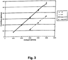
- the viscosity of the liquid acts as an offset, as is the case further FIG. 3 results. This can be determined by determining the increase in flux at variable speed a measure of the flow resistance of the circuit.
- the flow rate is an important parameter of the dialysis treatment, it should on average correspond to the preset value. This is achieved by regulation by means of a flow sensor. However, changes in viscosity and flow resistance cause the control to change the speed of the centrifugal pump. During the control process, the flux changes caused thereby are used to determine the slope dQ / dn, which is a measure of the flow resistance.
- a current measure of the flow resistance is always known. This measure can be used on the one hand to initiate countermeasures and on the other hand an easily understandable, non-technical indicator of the flow resistance, for example on a user interface, for. B. display a display of the blood treatment device, z. B. in the form of a battery level indicator or the like.
- This determination of the differential pressure can be as follows, for example, in the FIG. 1 be used shown blood treatment device:
- a test of the disposable articles used take place before each treatment, in particular a dialysis treatment.
- the extracorporeal circuits of dialysis machines are usually filled with saline solutions.
- the speed is varied and the resulting flow is measured.
- the measure of the flow resistance dQ / dn must lie within a certain range if the circuit is error-free. Otherwise, the presence of defective components is detected.
- the flow sensor of the extracorporeal blood circulation system of the dialysis machine can be functionally tested with this test.
- the flow rate is adjusted by means of regulation on average to a preset value.
- disturbance variables such as flow resistance or viscosity
- the flow change is observed in addition to the speed change in order to derive therefrom the measure of the flow resistance dQ / dn.
- FIG. 4 shows a flow chart of a reversible speed change for flow resistance determination.
- step S100 a control of Q blood to Q setpoint takes place .
- step S101 it is checked if a certain period of time T has elapsed. If this is not already the case, the system returns to step S100. If so a certain period of time T has already elapsed, the flow proceeds to step S102, which is to store the values for n1 and Q1.
- step S103 the speed is adjusted by ⁇ n.
- step S104 the storage of n2 and Q2 is performed. Then, in step S105, ⁇ Q / ⁇ n can be calculated.
- step S106 it is then checked whether the calculated value ⁇ Q / ⁇ n is within an allowable range. If so, it jumps back to step S100. If this is not the case, in step S107 a corresponding countermeasure or corresponding countermeasures are taken.
- the detection of an excessively increased flow resistance can be used to initiate an automatic blood return, which may be a countermeasure or part of the step S107, for example.
- Another countermeasure according to step S107 may also be to interrupt the treatment in terms of patient safety or initiate a different safe state.
- dQ / dn is a measure of the flow resistance of the blood circulation or extracorporeal blood circulation 10
- this value can also be used to provide an easy-to-understand and non-technical representation of the flow resistance for the operator of the device (z. B. in the style of a battery level indicator).
- An additional pressure sensor may be mounted, for example, in the extracorporeal blood circuit 10, such as between the centrifugal pump 20 and a dialyzer 30. This makes it possible to locate an increased flow resistance. If the measured pressure drops, then the increased flow resistance between patient P and pump 20 is increased. If the measured pressure rises, the increased flow resistance is behind pump 20, e.g. B. in the dialyzer 30. By locating it is possible to initiate targeted countermeasures.
- the rotational speed of the blood pump 20 and thus the suction pressure are greatly reduced. Since the pump 20 is not occlusive, the high negative pressure does not remain between the vessel wall and catheter or needle, but is degraded. Subsequently, the speed of the centrifugal pump 20 can be increased again and the treatment can be continued under pressure or time-controlled. If the bottleneck persists, for example, by kinking the patient's hose, the safe state must be initiated, ie a termination of the treatment is made and an alarm is issued.
- a corresponds to the gradient dQ / dn or to a parameter dependent on the flow resistance
- b corresponds to the offset or a parameter dependent on the viscosity. If one has determined the flow resistance parameter a as described, then b is calculated from the current / average flow and the current / average rotational speed to: b current ⁇ Q current - ⁇ ⁇ Q ⁇ ⁇ n n current
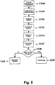
- FIG. 5 is a flowchart relating to the initial tests during start-up of the extracorporeal blood circuit 10 according to an embodiment of the present invention.
- step S200 the filling of the extracoporal blood circulation 10 is performed with a saline solution.
- step S201 a short circuit of the patient lines follows.
- step S202 the rotational speed of the centrifugal pump 20 is then adjusted according to FIG FIG. 1 approached at a speed n1.
- the flow Q1 is then stored.
- step S204 the speed is then increased to n2 and the extracoporal blood circuit 10 is operated therewith.
- step S205 the flow Q2 is further stored.
- step S206 the value dQ / dn is then calculated and checked whether this is within predetermined limits. If so, then in step S207 the treatment is released and, if this is not the case, an error message is issued in step S208.
Landscapes
- Health & Medical Sciences (AREA)
- Heart & Thoracic Surgery (AREA)
- Engineering & Computer Science (AREA)
- Animal Behavior & Ethology (AREA)
- Public Health (AREA)
- Veterinary Medicine (AREA)
- Anesthesiology (AREA)
- Biomedical Technology (AREA)
- Hematology (AREA)
- Life Sciences & Earth Sciences (AREA)
- General Health & Medical Sciences (AREA)
- Cardiology (AREA)
- Mechanical Engineering (AREA)
- Urology & Nephrology (AREA)
- Vascular Medicine (AREA)
- Emergency Medicine (AREA)
- Physics & Mathematics (AREA)
- Fluid Mechanics (AREA)
- Medical Informatics (AREA)
- Human Computer Interaction (AREA)
- Pulmonology (AREA)
- External Artificial Organs (AREA)
Description
- Die vorliegende Erfindung betrifft eine Blutbehandlungsvorrichtung mit wenigstens einer Impellerpumpe sowie ein Verfahren zur Inbetriebnahme einer Blutbehandlungsvorrichtung.
- Zentrifugalpumpen bzw. Impellerpumpen sind Druckquellen und finden im Bereich der Blutförderung Anwendung. Derartige Zentrifugalpumpen bzw. Impellerpumpen können als Alternative zu Verdrängerpumpen, insbesondere Schlauchrollenpumpen eingesetzt werden.
- Zentrifugalpumpen bzw. Impellerpumpen erzeugen im Gegensatz zu Flussquellen wie beispielsweise Schlauchrollenpumpen keinen von der Drehzahl abhängigen Durchfluss, sondern einen von der Drehzahl abhängigen Differenzdruck. Der Durchfluss von Zentrifugalpumpen stellt sich im Wesentlichen durch den Flusswiderstand des Kreislaufs und die Viskosität der Flüssigkeit ein.
- Der Flusswiderstand spielt in extrakorporalen Kreisläufen eine große Rolle: Ein veränderter Widerstand z. B. eines Dialysefilters in einem extrakorporalen Blutkreislauf zur Blutbehandlung deutet beispielsweise auf die Gerinnung von Blut hin. Sogenanntes Kinking, Clotting oder Stenosen können zu einer starken Veränderung des Widerstands der Leitungen führen. Das Ansaugen der arteriellen Nadel oder des Katheters an ein Gefäß des Patienten führt zu einem starken Anstieg des Flusswiderstands im Patientenzugang. Alle vorgenannten Ereignisse können relativ häufig während extrakorporaler Blutbehandlungen unter ungünstigen Voraussetzungen eintreten und können ferner potentiell zu einer Schädigung des Blutes führen. Vor diesem Hintergrund ist es wichtig, diese Vorgänge möglichst frühzeitig zu detektieren und Gegenmaßnahmen einzuleiten.
- Aus der
DE 10 2007 007 198 A1 ist bereits ein Verfahren und eine Vorrichtung zur Überwachung und Optimierung eines durch eine Pumpe bewirkten Blutkreislaufs bekannt. Dabei wird zur automatischen Regelung von Blutpumpen durch periodische Drehzahlinterventionen und die dabei auftretenden Flussänderungen über eine gebildete differentielle Größe und einen Regelalgorithmus eine Optimierung des Blutflusses erreicht. Zusätzlich kann die Lage von möglichen Flusswiderständen auf venöser oder arterieller Seite ermittelt werden. - Des Weiteren sind im Zusammenhang mit der Blutbehandlung Kassettensysteme bekannt, bei denen zumindest ein Teil des extrakorporalen Blutkreislaufs in einer disposablen Kassette zusammengefasst ist. Derartige Kassettensysteme werden beispielsweise bereits durch die
DE 10 2009 024 465 A1 sowie dieDE 10 2009 018 664 A1 offenbart. - Aus der
DE 10 2007 007 198 A1 ist ein Verfahren zum Betreiben von Blutpumpen innerhalb eines intra- oder extrakorporalen Blutkreislaufs mit nachfolgenden Verfahrensschritten bekannt: a) Ermittlung eines Schwellenwerts T, der ein Teil eines Mittelwerts aus gemessenen Kenngrößen DFSR ("Differential Flow Speed Ratio") ist, wobei die einzelnen DFSR-Kenngrößen aus dem Quotienten einer differenziellen Blutförderleistung zu einer dazu gemessenen differenziellen Blutpumpendrehzahl errechnet werden, wobei schrittweise die Blutpumpendrehzahl bis 3/4 des im Kreislauf benötigten Blutflusses erhöht wird und für jeden Veränderungsschritt eine DFSR-Kenngröße errechnet wird; b) Reduzierung der Blutpumpendrehzahl und schrittweise Berechnung der dazugehörigen DFSR-Kenngrößen; c) Vergleich der DFSR-Kenngrößen von Verfahrensschritt b) mit dem Schwellenwert T aus Verfahrensschritt a); d) Veränderung der Blutpumpendrehzahl je nachdem ob die DFSR-Kenngröße nach Verfahrensschritt b) größer oder kleiner als der Schwellenwert T ist. Weiterhin ist dort angegeben, dass Rückflusshindernisse den Flusswiderstand auf der Einlassseite der Pumpe erhöhen, was die Pumpenvorlast reduziert und den Pumpfluss negativ beeinflusst. Im Falle von Clotting eines Oxygenators ist der Widerstand gleichfalls erhöht, aber dieser zu sätzliche Widerstand tritt dann hinter der Pumpe auf. Beide Fälle beeinflussen DFSR, aber zur Unterscheidung zwischen Clotting des Oxygenators und Behinderung des venösen Rückflusses zur Pumpe kann die zusätzliche Messung des Druckabfalls über den Oxygenator (Druck am Einlass - Druck am Auslass) die benötigte Information liefern. Wenn DFSR abfällt, zeigt die Höhe des Differenzdrucks am Oxygenator die Ursache des gestiegenen Widerstands an, d. h. ob sie vor oder nach der Pumpe liegt. Falls der Differenzdruck gering ist, liegt eine Behinderung des venösen Rückflusses vor, bei hohem Differenzdruck ist Clotting des Oxygenators eingetreten. - Wünschenswert wäre es angesichts des vorgenannten Hintergrunds, eine einfache und zuverlässige Flusswiderstandsbestimmung bei Blutbehandlungsvorrichtungen mit extrakorporalen Kreisläufen, die über Zentrifugalpumpen bzw. Impellerpumpen verfügen, bereitstellen zu können.
- Es ist daher die Aufgabe der vorliegenden Erfindung, eine Blutbehandlungsvorrichtung sowie ein Verfahren zur Inbetriebnahme einer Blutbehandlungsvorrichtung der eingangs genannten Art in vorteilhafter Weise weiterzubilden.
- Diese Aufgabe wird erfindungsgemäß gelöst durch eine Blutbehandlungsvorrichtung mit den Merkmalen des Anspruchs 1.
- Gemäß der vorliegenden Erfindung ist vorgesehen, dass eine Blutbehandlungsvorrichtung wenigstens einen extrakorporalen Blutkreislauf mit einem Filterelement sowie wenigstens ein Zentrifugalpumpmittel aufweist, wobei ferner ein Überwachungsmittel vorgesehen ist, mittels dessen der Flusswiderstand des extrakorporalen Kreislaufs bei Inbetriebnahme des extrakorporalen Kreislaufs in einem initialen Test bei kurzgeschlossenen Patientenleitungen ermittelbar ist, wobei der Flusswiderstand zumindest teilweise anhand des Flusses in wenigstens einem Abschnitt des extrakorporalen Blutkreislaufs und der Drehzahl des Zentrifugalpumpmittels ermittelbar ist und wobei der extrakorporale Blutkreislauf zumindest teilweise durch eine disposable Kassette ausgebildet ist.
- Bei der Blutbehandlungsvorrichtung kann es sich beispielsweise um eine Hämodialysemaschine zum Einsatz für die Hämodialyse, Hämodiafiltration, Hämofiltration usw. handeln.
- Die erfindungsgemäße Blutbehandlungsvorrichtung erlaubt es insbesondere, ein direktes Maß des Flusswiderstands eines Kreislaufs ermitteln zu können. Darüber hinaus ist es möglich, einen initialen Test von Bestandteilen des extrakorporalen Blutkreislaufs durchführen zu können. Bei diesen Bestandteilen kann es sich insbesondere um Einwegartikel handeln.
- Darüber hinaus ist es möglich, beispielsweise Überwachungsmittel des extrakorporalen Blutkreislaufes wie beispielsweise Flusssensoren einem initialen, funktionalen Test unterziehen zu können.
- Darüber hinaus ist es möglich, eine Flusswiderstandsmessung unabhängig von der Viskosität des geförderten Mediums im extrakorporalen Blutkreislauf durchführen zu können, was beispielsweise bei einer Druckmessung nicht der Fall ist. Denn bei Flusswiderstandsmessungen basierend auf Druckmessungen ist es erforderlich, die Viskosität des geförderten Mediums, also beispielsweise die Viskosität des Blutes ermitteln zu müssen.
- Ferner ist es möglich, eine kontinuierliche Messung während der Blutflussregelung ohne einen zusätzlichen Test durchführen zu können.
- Ferner ist es sehr vorteilhaft möglich, nunmehr den Zusammenhang von Drehzahl und Fluss nutzen zu können, um die Viskosität des geförderten Mediums, beispielsweise des Blutes zu bestimmen.
- Erfindungsgemäß ist weiterhin vorgesehen, dass mittels des Überwachungsmittels in einem ersten Schritt der Fluss in dem wenigstens einen Abschnitt des extrakorporalen Blutkreislaufs bei einer ersten Drehzahl ermittelbar ist und in einem zweiten Schritt der Fluss in dem wenigstens einen Abschnitt des extrakorporalen Blutkreislaufs bei einer zweiten Drehzahl ermittelbar ist, wobei anhand dieser Werte als Maß für den Flusswiderstand das Verhältnis der Differenzwerte errechenbar ist. Das Maß für den Flusswiderstand ist das Verhältnis der Differenzwerte des Flusses Q1 in dem wenigstens einen Abschnitt des extrakorporalen Blutkreislaufs bei einer ersten Drehzahl n1 und dem Fluss Q2 in dem wenigstens einen Abschnitt des extrakorporalen Blutkreislaufs bei einer zweiten Drehzahl n2, also der Wert dQ/dn. Dabei wird mittels des Überwachungsmittels ein fehlerhafter Zustand des extrakorporalen Blutkreislaufs erkannt, wenn das Maß für den Flusswiderstand einen vordefinierten Bereich verlässt und/oder einen vordefinierten Schwellwert übersteigt oder unterschreitet. Dabei wird die Behandlung freigegeben, wenn das Maß für den Flusswiderstand (dQ/dn) innerhalb vorgegebener Grenzwerte liegt, und, falls dies nicht der Fall ist, eine Fehlermeldung ausgegeben.
- Des Weiteren kann vorgesehen sein, dass mittels des Überwachungsmittels bei Erkennung eines fehlerhaften Zustandes wenigstens eine Gegenmaßnahme einleitbar ist.
- Es ist ferner denkbar, dass die Gegenmaßnahme das Auslösen eines Alarmes und/oder die Veränderung der Drehzahl des Zentrifugalpumpmittels und/oder die Überführung der Blutbehandlungsvorrichtung in einen sicheren Zustand umfasst.
- Es ist möglich, dass wenigstens ein Anzeigemittel vorgesehen ist, mittels dessen das Maß für den Flusswiderstand darstellbar und/oder anzeigbar ist. Dadurch ergibt sich der Vorteil, eine leicht verständliche nicht technische Darstellung des Flusswiderstandes beispielsweise auf einem User Interface wie z. B. einem Display der Blutbehandlungsvorrichtung anzeigen zu können.
- Darüber hinaus kann vorgesehen sein, dass im extrakorporalen Blutkreislauf wenigstens ein Druckerfassungsmittel, insbesondere wenigstens ein Drucksensor, vorgesehen ist, mittels dessen der Druck in wenigstens einem Abschnitt des extrakorporalen Blutkreislaufs ermittelbar ist.
- Außerdem ist denkbar, dass mittels des Überwachungsmittels anhand des mittels des Druckerfassungsmittels ermittelten Druckes eine Stelle im extrakorporalen Blutkreislauf mit einem erhöhten Flusswiderstand ermittelbar ist.
- Denkbar ist, dass die Kassette wenigstens einen Schlauchabschnitt und/oder wenigstens eine Tropfkammer und/oder wenigstens ein Ventil und/oder wenigstens einen Filter und/oder das Filterelement aufweist.
- Des Weiteren betrifft die vorliegende Erfindung ein Verfahren zur Inbetriebnahme einer Blutbehandlungsvorrichtung mit den Merkmalen des Anspruchs 6.
- Danach ist vorgesehen, dass bei einem Verfahren zur Inbetriebnahme einer Blutbehandlungsvorrichtung, mit wenigstens einem extrakorporalen Blutkreislauf mit einem Filterelement sowie mit wenigstens einem Zentrifugalpumpmittel, wobei ferner ein Überwachungsmittel vorgesehen ist, mittels dessen der Flusswiderstand des extrakorporalen Kreislaufs bei Inbetriebnahme des extrakorporalen Kreislaufs in einem initialen Test bei kurzgeschlossenen Patientenleitungen ermittelt, der Flusswiderstand zumindest teilweise anhand des Flusses in wenigstens einem Abschnitt des extrakorporalen Blutkreislaufs und der Drehzahl des Zentrifugalpumpmittels ermittelt wird.
- Weiterhin ist vorgesehen, dass mittels des Überwachungsmittels in einem ersten Schritt der Fluss in dem wenigstens einen Abschnitt des extrakorporalen Blutkreislaufs bei einer ersten Drehzahl ermittelt wird und in einem zweiten Schritt der Fluss in dem wenigstens einen Abschnitt des extrakorporalen Blutkreislaufs bei einer zweiten Drehzahl ermittelt wird, wobei anhand dieser Werte als Maß für den Flusswiderstand das Verhältnis der Differenzwerte errechnet wird. Dabei wird mittels des Überwachungsmittels ein fehlerhafter Zustand des extrakorporalen Blutkreislaufs erkannt, wenn das Maß für den Flusswiderstand einen vordefinierten Bereich verlässt und/oder einen vordefinierten Schwellwert übersteigt oder unterschreitet, wobei die Behandlung freigegeben wird, wenn das Maß für den Flusswiderstand (dQ/dn) innerhalb vorgegebener Grenzwerte liegt, und, falls dies nicht der Fall ist, eine Fehlermeldung ausgegeben wird.
- Außerdem kann vorgesehen sein, dass mittels des Überwachungsmittels bei Erkennung eines fehlerhaften Zustandes wenigstens eine Gegenmaßnahme eingeleitet wird.
- Es ist ferner möglich, dass die Gegenmaßnahme das Auslösen eines Alarmes und/oder die Veränderung der Drehzahl des Zentrifugalpumpmittels und/oder die Überführung der Blutbehandlungsvorrichtung in einen sicheren Zustand umfasst.
- Darüber hinaus kann vorgesehen sein, dass mittels des Überwachungsmittels anhand eines ermittelten Druckes in wenigstens einem Abschnitt des extrakorporalen Blutkreislaufes eine Stelle im extrakorporalen Blutkreislauf mit einem erhöhten Flusswiderstand ermittelbar ist bzw. bei Vorliegen eines erhöhten Flusswiderstandes ermittelt wird.
- Weitere Einzelheiten und Vorteile der Erfindung sollen nun anhand eines in der Zeichnung dargestellten Ausführungsbeispiels näher erläutert werden.
- Es zeigen:
- Figur 1:
- eine schematische Darstellung des extrakorporalen Kreislaufs mit Zentrifugalpumpe, Dialysator, Flusssensor und Sicherheitsklemmen;
- Figur 2:
- ein Diagramm betreffend den Durchfluss in Abhängigkeit der Drehzahl bei unterschiedlichen Flusswiderständen und konstanter Viskosität;
- Figur 3:
- ein Diagramm betreffend den Durchfluss in Abhängigkeit der Drehzahl bei unterschiedlicher Viskosität und konstantem Flusswiderstand;
- Figur 4:
- ein Ablaufdiagramm einer reversiblen Drehzahländerung zur Flusswiderstandsbestimmung; und
- Figur 5:
- ein weiteres Ablaufdiagramm für die Inbetriebnahme der erfindungsgemäßen Blutbehandlungsvorrichtung.
-
Figur 1 zeigt in schematischer Darstellung einen extrakorporalen Blutkreislauf 10 einer erfindungsgemäßen Blutbehandlungsvorrichtung mit einer Zentrifugalpumpe 20, Dialysator 30, Flusssensor 50 und Sicherheitsklemmen 45 und 85. - Der extrakorporale Blutkreislauf 10 ist dabei Bestandteil einer Blutbehandlungsvorrichtung und wird durch die Zentrifugalpumpe 20 angetrieben. Stromabwärts der Zentrifugalpumpe 20 ist ein Dialysator 30 angeordnet, wobei es sich bei dem Dialysator 30 um einen Hohlfasermembrandialysator 30 handeln kann bzw. vorzugsweise handelt.
- Der Patient P wird über einen nicht näher dargestellten Katheter oder Nadeln an den extrakorporalen Blutkreislauf 10 angeschlossen, wobei der arterielle Anschluss 40 mit einer Klemme 45 versehen ist, so dass der arterielle Anschluss 40 abgeklemmt werden kann. Zwischen der Klemme 45 und der Zentrifugalpumpe 20 befindet sich ein Flusssensor 50. Der arterielle Teil des extrakorporalen Blutkreislaufs 10 ist mit dem Bezugszeichen 47 bezeichnet.
- Der venöse Teil 60 des extrakorporalen Blutkreislaufs 10 umfasst die Rückführleitung 62, die zum venösen Anschluss 80 führt, mit dem dem Patienten P das behandelte Blut zurückgegeben wird. Vor dem venösen Anschluss 80 ist eine Klemme 85 vorgesehen, mittels dessen dieser Anschluss abgeklemmt werden kann.
- Die vorliegende Erfindung basiert insbesondere auf der Erkenntnis, dass der Differenzdruck, der durch eine Zentrifugalpumpe wie durch die Zentrifugalpumpe 20 erzeugt wird, näherungsweise proportional zum Quadrat der Drehzahl der Zentrifugalpumpe ist:

- Weiterhin ist der Durchfluss bei konstanter Viskosität und konstantem Flusswiderstand näherungsweise proportional zur Quadratwurzel des Differenzdruckes:

- Daraus folgt, dass der Durchfluss bei konstantem Widerstand und konstanter Viskosität proportional zur Drehzahl der Zentrifugalpumpe ist:

- p = Druck,
- Q = Durchfluss,
- n = Drehzahl.
- Die Steigung dieses Zusammenhangs ist abhängig vom Flusswiderstand des Kreislaufs, wie sich dies insbesondere aus
Figur 2 ergibt, die ein Diagramm betreffend den Durchfluss in Abhängigkeit der Drehzahl bei unterschiedlichen Flusswiderständen und konstanter Viskosität zeigt. - Dabei wirkt sich die Viskosität der Flüssigkeit als Offset aus, wie sich dies weiter aus
Figur 3 ergibt. Dadurch kann man durch die Ermittlung des Flussanstiegs bei variabler Drehzahl ein Maß für den Flusswiderstand des Kreislaufs ermitteln. - Während einer Dialysebehandlung treten sowohl Änderungen der Viskosität, etwa durch Ultrafiltration etc., als auch Änderungen des Flusswiderstands durch Kinking, Clotting, Nadelansaugen etc. auf. Beide Änderungen haben einen direkten Einfluss auf den resultierenden Durchfluss.
- Da der Durchfluss ein wichtiger Parameter der Dialysebehandlung ist, sollte dieser im Mittel dem voreingestellten Wert entsprechen. Dies wird durch eine Regelung mittels Flusssensor erreicht. Änderungen in Viskosität und Flusswiderstand führen jedoch dazu, dass die Regelung die Drehzahl der Zentrifugalpumpe verändern muss. Während des Regelvorgangs werden die dadurch verursachten Flussänderungen genutzt, um die Steigung dQ/dn zu bestimmen, die ein Maß für den Flusswiderstand ist.
- Dadurch ist bekannt, ob die Änderung durch die Viskosität der Flüssigkeit oder den Flusswiderstand des Kreislaufs hervorgerufen wurde. Die Druckmessung im extrakorporalen Kreislauf ist hierzu nicht in der Lage, da sowohl Widerstands- als auch Viskositätsänderungen zu einer Änderung des Drucks führen.
- Zudem ist stets ein aktuelles Maß für den Flusswiderstand bekannt. Dieses Maß kann genutzt werden, um einerseits Gegenmaßnahmen einzuleiten und andererseits einen leicht verständlichen, nicht-technischen Indikator für den Flusswiderstand beispielsweise auf einem User-Interface, z. B. einem Display der Blutbehandlungsvorrichtung darzustellen, z. B. in Form einer Batteriefüllstandsanzeige oder ähnlichem.
- Diese Ermittlung des Differenzdruckes kann folgendermaßen beispielsweise bei der in
Figur 1 gezeigten Blutbehandlungsvorrichtung eingesetzt werden:
So kann beispielsweise vor jeder Behandlung, insbesondere einer Dialysebehandlung ein Test der verwendeten Einwegartikel stattfinden. Vor jeder Behandlung werden die extrakorporalen Kreisläufe von Dialysemaschinen in der Regel mit Kochsalzlösungen gefüllt. Bei kurz geschlossenen Patientenleitungen wird dabei die Drehzahl variiert und der resultierende Fluss gemessen. Das Maß für den Flusswiderstand dQ/dn muss dabei innerhalb eines bestimmten Bereichs liegen, wenn der Kreislauf fehlerfrei ist. Andernfalls wird das Vorliegen von fehlerhaften Komponenten detektiert. Mit diesem Test kann zugleich der Flusssensor des extrakorporalen Blutkreislaufs der Dialysemaschine funktional getestet werden. - Ferner ist es möglich, eine kontinuierliche Überwachung des Flusswiderstands während der Behandlung durchzuführen. Dabei wird der Durchfluss mittels Regelung im Mittel auf einen voreingestellten Wert eingeregelt. Bei der Ausregelung von Störgrößen wie Flusswiderstand oder Viskosität wird neben der Drehzahländerung auch die Flussänderung beobachtet, um daraus das Maß für den Flusswiderstand dQ/dn herzuleiten.
- Verhältnismäßig schnelle Vorgänge wie Kinking, Clotting oder das Ansaugen eines Katheters bzw. der arteriellen Nadel führen dazu, dass der Durchfluss zunächst absinkt und anschließend wieder ausgeregelt wird. Langsame Vorgänge, wie die Änderung der Viskosität durch Ultrafiltration werden kontinuierlich ausgeregelt. Als eine weitere Sicherheitsmaßnahme kann eine reversible Drehzahländerung durchgeführt werden, die entweder zeitlich gesteuert oder bei Überschreitung einer bestimmten Drehzahl beim bestimmten Fluss hervorgerufen wird. Ein Beispiel für diesen Vorgang ist in
Figur 4 dargestellt.Figur 4 zeigt dabei ein Ablaufdiagramm einer reversiblen Drehzahländerung zur Flusswiderstandsbestimmung. - In Schritt S100 erfolgt eine Regelung von QBlut auf QSoll.
- In Schritt S101 wird überprüft, ob eine bestimmte Zeitspanne T verstrichen ist. Sofern dies noch nicht der Fall ist, wird zu Schritt S100 zurückgekehrt. Sofern jedoch eine bestimmte Zeitspanne T bereits verstrichen ist, wird mit Schritt S102 fortgefahren, der darin besteht, die Werte für n1 und Q1 einzuspeichern.
- Sodann erfolgt in Schritt S103 ein Verstellen der Drehzahl um Δn.
- Sodann erfolgt in Schritt S104 das Einspeichern von n2 und Q2. In Schritt S105 kann sodann ΔQ/Δn berechnet werden.
- In Schritt S106 wird sodann überprüft, ob der berechnete Wert ΔQ/Δn sich innerhalb eines erlaubten Bereichs befindet. Ist dies der Fall, wird zurück in Schritt S100 gesprungen. Sollte dies nicht der Fall sein, erfolgt in Schritt S107 eine entsprechende Gegenmaßnahme oder entsprechende Gegenmaßnahmen.
- Die Detektion eines zu stark gestiegenen Flusswiderstands kann genutzt werden, um eine automatische Blutrückgabe einzuleiten, was beispielsweise eine Gegenmaßnahme bzw. Bestandteil des Schrittes S107 sein kann. Eine weitere Gegenmaßnahme gemäß Schritt S107 kann auch darin bestehen, die Behandlung im Sinne der Patientensicherheit zu unterbrechen oder einen anders gearteten sicheren Zustand einzuleiten.
- Darüber hinaus ist es möglich, eine leicht verständliche Darstellung des Flusswiderstandes für Bediener und Patienten der Blutbehandlungsvorrichtung zu ermöglichen.
- Da der Wert dQ/dn ein Maß für den Flusswiderstand des Blutkreislaufs bzw. extrakorporalen Blutkreislaufs 10 ist, kann dieser Wert auch genutzt werden, um eine leicht verständliche und nicht-technische Darstellung des Flusswiderstands für den Bediener des Gerätes zur Verfügung zu stellen (z. B. im Stil einer Batteriefüllstandsanzeige).
- Dabei kann beispielsweise der Wert von dQ/dn, der beim initialen Test des Einwegartikels genutzt werden, um den Wert zu normieren. So würden 100 % dem initialen Wert der Steigung entsprechen, während 0 % ein Wert ist, über den das Fördern von Blut durch den extrakoporalen Kreislauf 10 nicht mehr ohne stark erhöhte Blutschädigung durchgeführt werden kann.
- Darüber hinaus ist es möglich, eine Ortung der Flusswiderstandserhöhung, also der Stelle, an der die Erhöhung des Flusswiderstands hervorgerufen wird, zu detektieren.
- Ein zusätzlicher Drucksensor kann beispielsweise im extrakorporalen Blutkreislauf 10 angebracht werden, etwa zwischen der Zentrifugalpumpe 20 und einem Dialysator 30. Hierdurch wird es ermöglicht, einen erhöhten Flusswiderstand zu orten. Fällt der gemessene Druck ab, so befindet sich der erhöhte Flusswiderstand zwischen Patient P und Pumpe 20. Steigt der gemessene Druck an, so befindet sich der erhöhte Flusswiderstand hinter der Pumpe 20, z. B. im Dialysator 30. Durch die Ortung wird es ermöglicht, gezielt Gegenmaßnahmen einleiten zu können.
- Bei einem angesaugten Katheter bzw. Nadel wird beispielsweise die Drehzahl der Blutpumpe 20 und damit der Saugdruck stark gedrosselt. Da die Pumpe 20 nicht okkludierend ist, verbleibt der hohe Unterdruck nicht zwischen Gefäßwand und Katheter bzw. Nadel, sondern wird abgebaut. Anschließend kann Druck oder zeitgesteuert die Drehzahl der Zentrifugalpumpe 20 wieder gesteigert und die Behandlung fortgesetzt werden. Bleibt die Engstelle bestehen, beispielsweise durch Kinking des Patientenschlauches, muss der sichere Zustand eingeleitet werden, also ein Abbruch der Behandlung vorgenommen und ein Alarm ausgegeben werden.
- Ferner ist es möglich, die Viskosität zu bestimmen. Wie sich dies aus
Figur 1 und2 ergibt, ist es möglich, die Viskosität der Flüssigkeit aus der Drehzahl der Pumpe 20 und dem Durchfluss des Systems zu bestimmen. Beschreibt man den Zusammenhang von Drehzahl und Durchfluss näherungsweise mit

-
Figur 5 zeigt ein Ablaufdiagramm betreffend die initialen Tests bei der Inbetriebnahme des extrakorporalen Blutkreislaufs 10 gemäß einem Ausführungsbeispiel der vorliegenden Erfindung. Dabei wird im Schritt S200 das Füllen des extrakoporalen Blutkreislaufs 10 mit einer Kochsalzlösung durchgeführt. Sodann folgt in Schritt S201 ein Kurzschluss der Patientenleitungen. In Schritt S202 wird sodann die Drehzahl der Zentrifugalpumpe 20 gemäßFigur 1 mit einer Drehzahl n1 angefahren. In Schritt S203 wird sodann der Durchfluss Q1 gespeichert. - In Schritt S204 wird sodann die Drehzahl auf n2 erhöht und der extrakoporale Blutkreislauf 10 damit betrieben. In Schritt S205 wird ferner der Durchfluss Q2 gespeichert.
- In Schritt S206 wird daraufhin der Wert dQ/dn errechnet und überprüft, ob dieser innerhalb vorgegebener Grenzwerte liegt. Sollte dies der Fall sein, wird in Schritt S207 die Behandlung freigegeben und sofern dies nicht der Fall sein sollte, in Schritt S208 dementsprechend eine Fehlermeldung ausgegeben.
Claims (8)
- Blutbehandlungsvorrichtung mit wenigstens einem extrakorporalen Blutkreislauf (10) mit einem Dialysator (30) sowie mit wenigstens einem Zentrifugalpumpmittel (20), wobei ferner ein Überwachungsmittel vorgesehen ist, mittels dessen der Flusswiderstand des extrakorporalen Kreislaufs (10) bei Inbetriebnahme des extrakorporalen Kreislaufs (10) in einem initialen Test bei kurzgeschlossenen Patientenleitungen ermittelt wird, wobei der Flusswiderstand zumindest teilweise anhand des Flusses (Q) in wenigstens einem Abschnitt des extrakorporalen Blutkreislaufs und der Drehzahl (n) des Zentrifugalpumpmittels ermittelt wird und wobei der extrakorporale Blutkreislauf (10) zumindest teilweise durch eine disposable Kassette ausgebildet ist, wobei mittels des Überwachungsmittels in einem ersten Schritt der Fluss (Q1) in dem wenigstens einen Abschnitt des extrakorporalen Blutkreislaufs (10) bei einer ersten Drehzahl (n1) ermittelt wird und in einem zweiten Schritt der Fluss (Q2) in dem wenigstens einen Abschnitt des extrakorporalen Blutkreislaufs (10) bei einer zweiten Drehzahl (n2) ermittelt wird, wobei anhand dieser Werte (Q1, Q2; n1, n2) als Maß für den Flusswiderstand (dQ/dn) das Verhältnis der Differenzwerte errechnet wird, und wobei mittels des Überwachungsmittels ein fehlerhafter Zustand des extrakorporalen Blutkreislaufs (10) erkannt wird, wenn das Maß für den Flusswiderstand (dQ/dn) einen vordefinierten Bereich verlässt und/oder einen vordefinierte Schwellwert übersteigt oder unterschreitet, wobei die Behandlung freigegeben wird, wenn das Maß für den Flusswiderstand (dQ/dn) innerhalb vorgegebener Grenzwerte liegt, und, falls dies nicht der Fall ist, eine Fehlermeldung ausgegeben wird.
- Blutbehandlungsvorrichtung nach Anspruch 1, dadurch gekennzeichnet, dass wenigstens ein Anzeigemittel vorgesehen ist, mittels dessen das Maß für den Flusswiderstand (dQ/dn) dargestellt und/oder angezeigt wird.
- Blutbehandlungsvorrichtung nach einem der vorhergehenden Ansprüche, dadurch gekennzeichnet, dass im extrakorporalen Blutkreislauf (10) wenigstens ein Druckerfassungsmittel, insbesondere wenigstens ein Drucksensor, vorgesehen ist, mittels dessen der Druck in wenigstens einem Abschnitt des extrakorporalen Blutkreislaufs ermittelt wird.
- Blutbehandlungsvorrichtung nach Anspruch 3, dadurch gekennzeichnet, dass mittels des Überwachungsmittels anhand des mittels des Druckerfassungsmittels ermittelten Druckes eine Stelle im extrakorporalen Blutkreislauf mit einem erhöhten Flusswiderstand ermittelt wird.
- Blutbehandlungsvorrichtung nach einem der vorhergehenden Ansprüche, dadurch gekennzeichnet, dass die Kassette wenigstens einen Schlauchabschnitt und/oder wenigstens eine Tropfkammer und/oder wenigstens ein Ventil und/oder wenigstens einen Filter und/oder den Dialysator (30) aufweist.
- Verfahren zur Inbetriebnahmeeiner Blutbehandlungsvorrichtung mit wenigstens einem extrakorporalen Blutkreislauf (10) mit einem Dialysator (30) sowie mit wenigstens einem Zentrifugalpumpmittel (20), wobei ferner ein Überwachungsmittel vorgesehen ist, mittels dessen der Flusswiderstand des extrakorporalen Kreislaufs (10) bei Inbetriebnahme des extrakorporalen Kreislaufs (10) in einem initialen Test bei kurzgeschlossenen Patientenleitungen ermittelt wird, wobei der Flusswiderstand zumindest teilweise anhand des Flusses (Q) in wenigstens einem Abschnitt des extrakorporalen Blutkreislaufs und der Drehzahl (n) des Zentrifugalpumpmittels ermittelt wird, wobei der extrakorporale Blutkreislauf (10) zumindest teilweise durch eine disposable Kassette ausgebildet ist, wobei mittels des Überwachungsmittels in einem ersten Schritt der Fluss (Q1) in dem wenigstens einen Abschnitt des extrakorporalen Blutkreislaufs (10) bei einer ersten Drehzahl (n1) ermittelt wird und in einem zweiten Schritt der Fluss (Q2) in dem wenigstens einen Abschnitt des extrakorporalen Blutkreislaufs (10) bei einer zweiten Drehzahl (n2) ermittelt wird, wobei anhand dieser Werte (Q1, Q2; n1, n2) als Maß für den Flusswiderstand (dQ/dn) das Verhältnis der Differenzwerte errechnet wird, wobei mittels des Überwachungsmittels ein fehlerhafter Zustand des extrakorporalen Blutkreislaufs (10) erkannt wird, wenn das Maß für den Flusswiderstand (dQ/dn) einen vordefinierten Bereich verlässt und/oder einen vordefinierte Schwellwert übersteigt oder unterschreitet, wobei die Behandlung freigegeben wird, wenn das Maß für den Flusswiderstand (dQ/dn) innerhalb vorgegebener Grenzwerte liegt, und, falls dies nicht der Fall ist, eine Fehlermeldung ausgegeben wird.
- Verfahren nach Anspruch 6, dadurch gekennzeichnet, dass mittels des Überwachungsmittels anhand eines ermittelten Druckes in wenigstens einem Abschnitt des extrakorporalen Blutkreislaufes eine Stelle im extrakorporalen Blutkreislauf mit einem erhöhten Flusswiderstand ermittelbar ist oder bei Vorliegen eines erhöhten Flusswiderstandes ermittelt wird.
- Verfahren nach einem der Ansprüche 6 bis 7 zum Betrieb einer Blutbehandlungsvorrichtung gemäß einem der Ansprüche 1 bis 5.
Applications Claiming Priority (3)
| Application Number | Priority Date | Filing Date | Title |
|---|---|---|---|
| US201161530554P | 2011-09-02 | 2011-09-02 | |
| DE102011112221.8A DE102011112221B4 (de) | 2011-09-02 | 2011-09-02 | Blutbehandlungsvorrichtung |
| PCT/EP2012/003628 WO2013029786A1 (de) | 2011-09-02 | 2012-08-29 | Blutbehandlungsvorrichtung |
Publications (2)
| Publication Number | Publication Date |
|---|---|
| EP2750732A1 EP2750732A1 (de) | 2014-07-09 |
| EP2750732B1 true EP2750732B1 (de) | 2019-10-09 |
Family
ID=47710655
Family Applications (1)
| Application Number | Title | Priority Date | Filing Date |
|---|---|---|---|
| EP12755797.3A Active EP2750732B1 (de) | 2011-09-02 | 2012-08-29 | Blutbehandlungsvorrichtung |
Country Status (4)
| Country | Link |
|---|---|
| US (1) | US20130233798A1 (de) |
| EP (1) | EP2750732B1 (de) |
| DE (1) | DE102011112221B4 (de) |
| WO (1) | WO2013029786A1 (de) |
Families Citing this family (26)
| Publication number | Priority date | Publication date | Assignee | Title |
|---|---|---|---|---|
| US10089443B2 (en) | 2012-05-15 | 2018-10-02 | Baxter International Inc. | Home medical device systems and methods for therapy prescription and tracking, servicing and inventory |
| WO2011063906A1 (de) | 2009-11-26 | 2011-06-03 | Fresenius Medical Care Deutschland Gmbh | Verfahren zum regeln der zufuhr von substituat bei einer extrakorporalen blutbehandlung und extrakorporale blutbehandlungsvorrichtung mit einer einrichtung zum regeln der zufuhr von substituat |
| US10688233B2 (en) | 2014-12-19 | 2020-06-23 | Fenwal, Inc. | Method and system for the automated processing of biological fluid during low level alert condition |
| JP6437349B2 (ja) | 2015-03-10 | 2018-12-12 | 日機装株式会社 | 血液浄化装置 |
| DE102015011424A1 (de) * | 2015-09-01 | 2017-03-02 | Fresenius Medical Care Deutschland Gmbh | Verfahren zur Kalibrierung und / oder Überwachung eines Flusssensors |
| EP4732889A2 (de) | 2017-06-07 | 2026-04-29 | Supira Medical, Inc. | Vorrichtungen, systeme und verfahren zur bewegung intravaskulärer flüssigkeiten |
| JP7319266B2 (ja) | 2017-11-13 | 2023-08-01 | シファメド・ホールディングス・エルエルシー | 血管内流体移動デバイス、システム、および使用方法 |
| EP4085965A1 (de) | 2018-02-01 | 2022-11-09 | Shifamed Holdings, LLC | Intravaskuläre blutpumpen und verfahren zur verwendung und herstellung |
| US12161857B2 (en) | 2018-07-31 | 2024-12-10 | Shifamed Holdings, Llc | Intravascular blood pumps and methods of use |
| WO2020073047A1 (en) | 2018-10-05 | 2020-04-09 | Shifamed Holdings, Llc | Intravascular blood pumps and methods of use |
| EP3996797A4 (de) | 2019-07-12 | 2023-08-02 | Shifamed Holdings, LLC | Intravaskuläre blutpumpen und verfahren zur herstellung und verwendung |
| US11654275B2 (en) | 2019-07-22 | 2023-05-23 | Shifamed Holdings, Llc | Intravascular blood pumps with struts and methods of use and manufacture |
| EP4010046A4 (de) | 2019-08-07 | 2023-08-30 | Calomeni, Michael | Katheterblutpumpen und zusammenklappbare pumpengehäuse |
| JP7357343B2 (ja) * | 2019-08-30 | 2023-10-06 | 国立研究開発法人産業技術総合研究所 | 血液浄化装置 |
| EP4034192B1 (de) | 2019-09-25 | 2025-12-24 | Supira Medical, Inc. | Intravaskuläre blutpumpensysteme und verfahren zur verwendung und steuerung davon |
| US12102815B2 (en) | 2019-09-25 | 2024-10-01 | Shifamed Holdings, Llc | Catheter blood pumps and collapsible pump housings |
| US12121713B2 (en) | 2019-09-25 | 2024-10-22 | Shifamed Holdings, Llc | Catheter blood pumps and collapsible blood conduits |
| CA3160871A1 (en) | 2019-11-12 | 2021-05-20 | Fresenius Medical Care Deutschland Gmbh | Blood treatment systems |
| CN114728117B (zh) | 2019-11-12 | 2025-11-11 | 费森尤斯医疗护理德国有限责任公司 | 血液治疗系统 |
| CA3160967A1 (en) | 2019-11-12 | 2021-05-20 | Fresenius Medical Care Deutschland Gmbh | Blood treatment systems |
| CA3160952A1 (en) | 2019-11-12 | 2021-05-20 | Fresenius Medical Care Deutschland Gmbh | Blood treatment systems |
| EP4058094A1 (de) | 2019-11-12 | 2022-09-21 | Fresenius Medical Care Deutschland GmbH | Blutbehandlungssysteme |
| CN114728159B (zh) | 2019-11-12 | 2025-10-17 | 费森尤斯医疗护理德国有限责任公司 | 血液治疗系统 |
| EP4072650A4 (de) | 2019-12-11 | 2024-01-10 | Shifamed Holdings, LLC | Absteigende aorten- und hohlvenenblutpumpen |
| WO2021119401A1 (en) | 2019-12-12 | 2021-06-17 | Fresenius Medical Care Holdings, Inc. | Blood treatment systems |
| WO2021127503A1 (en) | 2019-12-19 | 2021-06-24 | Shifamed Holdings, Llc | Intravascular blood pumps, motors, and fluid control |
Family Cites Families (16)
| Publication number | Priority date | Publication date | Assignee | Title |
|---|---|---|---|---|
| US4898576A (en) * | 1986-06-06 | 1990-02-06 | Philip James H | Intravenous fluid flow monitor |
| US5609576A (en) * | 1994-09-13 | 1997-03-11 | Ivac Medical Systems, Inc. | Fluid flow impedance monitoring system |
| DE4440363C2 (de) * | 1994-11-11 | 1997-10-02 | Netzsch Newamatic Gmbh | Verfahren zum Prüfen und Reinigen von Instrumenten für die minimal invasive Chirurgie oder minimal invasive Untersuchung von Körperhöhlen |
| US6877713B1 (en) * | 1999-07-20 | 2005-04-12 | Deka Products Limited Partnership | Tube occluder and method for occluding collapsible tubes |
| JP4691503B2 (ja) * | 2003-10-28 | 2011-06-01 | バクスター・インターナショナル・インコーポレイテッド | 医療用流体システムのための、改善されたプライミング、一体性および水頭高さの方法および装置 |
| US20050209563A1 (en) * | 2004-03-19 | 2005-09-22 | Peter Hopping | Cassette-based dialysis medical fluid therapy systems, apparatuses and methods |
| DE102007007198A1 (de) | 2007-02-09 | 2008-08-14 | Maquet Cardiopulmonary Ag | Verfahren und Vorrichtung zur Überwachung und Optimierung eines durch eine Pumpe bewirkten Blutkreislaufs |
| US8409441B2 (en) * | 2007-02-27 | 2013-04-02 | Deka Products Limited Partnership | Blood treatment systems and methods |
| US8388567B2 (en) * | 2007-04-12 | 2013-03-05 | Gambro Lundia Ab | Apparatus for extracorporeal blood treatment |
| US8858787B2 (en) * | 2007-10-22 | 2014-10-14 | Baxter International Inc. | Dialysis system having non-invasive fluid velocity sensing |
| EP2227268B2 (de) * | 2007-10-24 | 2023-08-23 | Nikkiso Co., Ltd. | Optimierung der clearance von proteingebundenen molekülen mit kaskaden-filtrationstherapie |
| US8114276B2 (en) * | 2007-10-24 | 2012-02-14 | Baxter International Inc. | Personal hemodialysis system |
| DE102009024465B4 (de) | 2009-06-10 | 2015-03-05 | Fresenius Medical Care Deutschland Gmbh | Blutkassette mit Luftabscheider, Blutkreislauf sowie Behandlungsvorrichtung |
| DE102009018664A1 (de) | 2009-04-23 | 2010-10-28 | Fresenius Medical Care Deutschland Gmbh | Externe Funktionseinrichtung, Blutbehandlungsvorrichtung zum Aufnehmen einer erfindungsgemäßen externen Funktionseinrichtung, sowie Verfahren |
| DE102009027195A1 (de) * | 2009-06-25 | 2010-12-30 | Sorin Group Deutschland Gmbh | Vorrichtung zur Förderung von Blut in einem extrakorporalen Kreislauf |
| WO2011063906A1 (de) * | 2009-11-26 | 2011-06-03 | Fresenius Medical Care Deutschland Gmbh | Verfahren zum regeln der zufuhr von substituat bei einer extrakorporalen blutbehandlung und extrakorporale blutbehandlungsvorrichtung mit einer einrichtung zum regeln der zufuhr von substituat |
-
2011
- 2011-09-02 DE DE102011112221.8A patent/DE102011112221B4/de active Active
-
2012
- 2012-08-29 EP EP12755797.3A patent/EP2750732B1/de active Active
- 2012-08-29 US US13/597,517 patent/US20130233798A1/en not_active Abandoned
- 2012-08-29 WO PCT/EP2012/003628 patent/WO2013029786A1/de not_active Ceased
Non-Patent Citations (1)
| Title |
|---|
| None * |
Also Published As
| Publication number | Publication date |
|---|---|
| EP2750732A1 (de) | 2014-07-09 |
| US20130233798A1 (en) | 2013-09-12 |
| DE102011112221A1 (de) | 2013-03-07 |
| WO2013029786A1 (de) | 2013-03-07 |
| DE102011112221B4 (de) | 2017-05-24 |
Similar Documents
| Publication | Publication Date | Title |
|---|---|---|
| EP2750732B1 (de) | Blutbehandlungsvorrichtung | |
| EP1584339B1 (de) | Verfahren und Vorrichtung zur Überwachung eines Gefäßzugangs | |
| EP3096808B1 (de) | Vorrichtung zur regelung und vorgabe der pumprate von blutpumpen | |
| EP2431064B1 (de) | Vorrichtung zur Steuerung einer Einrichtung zum Fördern von Blut | |
| EP2519282B1 (de) | Vorrichtung und verfahren zur überwachung einer extrakorporalen blutbehandlung | |
| EP1327457B1 (de) | Vorrichtung zur Detektion einer Leckage in einem Flüssigkeitssystem einer Blutbehandlungsvorrichtung | |
| EP2203198B1 (de) | Verfahren und vorrichtung zur überwachung der zufuhr von substitutionsflüssigkeit während einer extrakorporalen blutbehandlung | |
| EP0895787B1 (de) | Verfahren zur Überwachung eines Gefässzuganges während einer Dialysebehandlung und Vorrichtung zur Dialysebehandlung mit einer Einrichtung zur Überwachung eines Gefässzuganges | |
| EP1356836B1 (de) | Vorrichtung zur extrakorporalen Blutbehandlung | |
| EP2913072B1 (de) | System zur Erkennung einer venösen Nadeldiskonnektion | |
| EP1994284B1 (de) | Verfahren und vorrichtung zum betreiben einer elektrischen peristaltischen schlauchpumpe | |
| EP3445418B1 (de) | Medizinische behandlungsvorrichtung und verfahren zur überwachung einer medizinischen behandlungsvorrichtung | |
| EP2349394B1 (de) | Verfahren und vorrichtung zur erkennung einer paravasalen blutung | |
| EP2432518B1 (de) | Vorrichtung und verfahren zur erkennung eines schlauchleitungssystems für eine extrakorporale blutbehandlungsvorrichtung | |
| EP3568170B1 (de) | Extrakorporale blutbehandlungsvorrichtung und verfahren zur überwachung der integrität eines dialysators einer extrakorporalen blutbehandlungsvorrichtung | |
| EP2736561B1 (de) | Verfahren sowie vorrichtungen zum ablösen von gasansammlungen von einem gerinnselfänger eines extrakorporalen blutkreislaufs | |
| EP2986332B1 (de) | Verfahren zur ermittlung des druckes in einem extrakorporalen kreislauf | |
| EP2152335B1 (de) | Vorrichtung zur Blutbehandlung für den Einnadel-Betrieb | |
| DE10033192B4 (de) | Verfahren zur Detektion arterieller Einlaufprobleme während einer extrakorporalen Blutbehandlung und extrakorporale Blutbehandlungsvorrichtung | |
| EP3487556B1 (de) | Dialysegerät zur korrektur des blutflusswertes | |
| WO2015086384A1 (de) | Vorrichtung und verfahren zur überwachung des venösen gefässzugangs bei einer extrakorporalen blutbehandlung |
Legal Events
| Date | Code | Title | Description |
|---|---|---|---|
| PUAI | Public reference made under article 153(3) epc to a published international application that has entered the european phase |
Free format text: ORIGINAL CODE: 0009012 |
|
| 17P | Request for examination filed |
Effective date: 20140325 |
|
| AK | Designated contracting states |
Kind code of ref document: A1 Designated state(s): AL AT BE BG CH CY CZ DE DK EE ES FI FR GB GR HR HU IE IS IT LI LT LU LV MC MK MT NL NO PL PT RO RS SE SI SK SM TR |
|
| DAX | Request for extension of the european patent (deleted) | ||
| 17Q | First examination report despatched |
Effective date: 20160411 |
|
| STAA | Information on the status of an ep patent application or granted ep patent |
Free format text: STATUS: EXAMINATION IS IN PROGRESS |
|
| GRAP | Despatch of communication of intention to grant a patent |
Free format text: ORIGINAL CODE: EPIDOSNIGR1 |
|
| STAA | Information on the status of an ep patent application or granted ep patent |
Free format text: STATUS: GRANT OF PATENT IS INTENDED |
|
| INTG | Intention to grant announced |
Effective date: 20190429 |
|
| GRAS | Grant fee paid |
Free format text: ORIGINAL CODE: EPIDOSNIGR3 |
|
| GRAA | (expected) grant |
Free format text: ORIGINAL CODE: 0009210 |
|
| STAA | Information on the status of an ep patent application or granted ep patent |
Free format text: STATUS: THE PATENT HAS BEEN GRANTED |
|
| AK | Designated contracting states |
Kind code of ref document: B1 Designated state(s): AL AT BE BG CH CY CZ DE DK EE ES FI FR GB GR HR HU IE IS IT LI LT LU LV MC MK MT NL NO PL PT RO RS SE SI SK SM TR |
|
| REG | Reference to a national code |
Ref country code: GB Ref legal event code: FG4D Free format text: NOT ENGLISH |
|
| REG | Reference to a national code |
Ref country code: CH Ref legal event code: EP |
|
| REG | Reference to a national code |
Ref country code: DE Ref legal event code: R096 Ref document number: 502012015384 Country of ref document: DE |
|
| REG | Reference to a national code |
Ref country code: IE Ref legal event code: FG4D Free format text: LANGUAGE OF EP DOCUMENT: GERMAN |
|
| REG | Reference to a national code |
Ref country code: AT Ref legal event code: REF Ref document number: 1188050 Country of ref document: AT Kind code of ref document: T Effective date: 20191115 |
|
| REG | Reference to a national code |
Ref country code: NL Ref legal event code: MP Effective date: 20191009 |
|
| REG | Reference to a national code |
Ref country code: LT Ref legal event code: MG4D |
|
| PG25 | Lapsed in a contracting state [announced via postgrant information from national office to epo] |
Ref country code: BG Free format text: LAPSE BECAUSE OF FAILURE TO SUBMIT A TRANSLATION OF THE DESCRIPTION OR TO PAY THE FEE WITHIN THE PRESCRIBED TIME-LIMIT Effective date: 20200109 Ref country code: FI Free format text: LAPSE BECAUSE OF FAILURE TO SUBMIT A TRANSLATION OF THE DESCRIPTION OR TO PAY THE FEE WITHIN THE PRESCRIBED TIME-LIMIT Effective date: 20191009 Ref country code: NO Free format text: LAPSE BECAUSE OF FAILURE TO SUBMIT A TRANSLATION OF THE DESCRIPTION OR TO PAY THE FEE WITHIN THE PRESCRIBED TIME-LIMIT Effective date: 20200109 Ref country code: NL Free format text: LAPSE BECAUSE OF FAILURE TO SUBMIT A TRANSLATION OF THE DESCRIPTION OR TO PAY THE FEE WITHIN THE PRESCRIBED TIME-LIMIT Effective date: 20191009 Ref country code: PL Free format text: LAPSE BECAUSE OF FAILURE TO SUBMIT A TRANSLATION OF THE DESCRIPTION OR TO PAY THE FEE WITHIN THE PRESCRIBED TIME-LIMIT Effective date: 20191009 Ref country code: LT Free format text: LAPSE BECAUSE OF FAILURE TO SUBMIT A TRANSLATION OF THE DESCRIPTION OR TO PAY THE FEE WITHIN THE PRESCRIBED TIME-LIMIT Effective date: 20191009 Ref country code: ES Free format text: LAPSE BECAUSE OF FAILURE TO SUBMIT A TRANSLATION OF THE DESCRIPTION OR TO PAY THE FEE WITHIN THE PRESCRIBED TIME-LIMIT Effective date: 20191009 Ref country code: PT Free format text: LAPSE BECAUSE OF FAILURE TO SUBMIT A TRANSLATION OF THE DESCRIPTION OR TO PAY THE FEE WITHIN THE PRESCRIBED TIME-LIMIT Effective date: 20200210 Ref country code: SE Free format text: LAPSE BECAUSE OF FAILURE TO SUBMIT A TRANSLATION OF THE DESCRIPTION OR TO PAY THE FEE WITHIN THE PRESCRIBED TIME-LIMIT Effective date: 20191009 Ref country code: LV Free format text: LAPSE BECAUSE OF FAILURE TO SUBMIT A TRANSLATION OF THE DESCRIPTION OR TO PAY THE FEE WITHIN THE PRESCRIBED TIME-LIMIT Effective date: 20191009 Ref country code: GR Free format text: LAPSE BECAUSE OF FAILURE TO SUBMIT A TRANSLATION OF THE DESCRIPTION OR TO PAY THE FEE WITHIN THE PRESCRIBED TIME-LIMIT Effective date: 20200110 |
|
| PG25 | Lapsed in a contracting state [announced via postgrant information from national office to epo] |
Ref country code: IS Free format text: LAPSE BECAUSE OF FAILURE TO SUBMIT A TRANSLATION OF THE DESCRIPTION OR TO PAY THE FEE WITHIN THE PRESCRIBED TIME-LIMIT Effective date: 20200224 Ref country code: RS Free format text: LAPSE BECAUSE OF FAILURE TO SUBMIT A TRANSLATION OF THE DESCRIPTION OR TO PAY THE FEE WITHIN THE PRESCRIBED TIME-LIMIT Effective date: 20191009 Ref country code: HR Free format text: LAPSE BECAUSE OF FAILURE TO SUBMIT A TRANSLATION OF THE DESCRIPTION OR TO PAY THE FEE WITHIN THE PRESCRIBED TIME-LIMIT Effective date: 20191009 |
|
| PG25 | Lapsed in a contracting state [announced via postgrant information from national office to epo] |
Ref country code: AL Free format text: LAPSE BECAUSE OF FAILURE TO SUBMIT A TRANSLATION OF THE DESCRIPTION OR TO PAY THE FEE WITHIN THE PRESCRIBED TIME-LIMIT Effective date: 20191009 |
|
| REG | Reference to a national code |
Ref country code: DE Ref legal event code: R097 Ref document number: 502012015384 Country of ref document: DE |
|
| PG2D | Information on lapse in contracting state deleted |
Ref country code: IS |
|
| PG25 | Lapsed in a contracting state [announced via postgrant information from national office to epo] |
Ref country code: DK Free format text: LAPSE BECAUSE OF FAILURE TO SUBMIT A TRANSLATION OF THE DESCRIPTION OR TO PAY THE FEE WITHIN THE PRESCRIBED TIME-LIMIT Effective date: 20191009 Ref country code: EE Free format text: LAPSE BECAUSE OF FAILURE TO SUBMIT A TRANSLATION OF THE DESCRIPTION OR TO PAY THE FEE WITHIN THE PRESCRIBED TIME-LIMIT Effective date: 20191009 Ref country code: RO Free format text: LAPSE BECAUSE OF FAILURE TO SUBMIT A TRANSLATION OF THE DESCRIPTION OR TO PAY THE FEE WITHIN THE PRESCRIBED TIME-LIMIT Effective date: 20191009 Ref country code: CZ Free format text: LAPSE BECAUSE OF FAILURE TO SUBMIT A TRANSLATION OF THE DESCRIPTION OR TO PAY THE FEE WITHIN THE PRESCRIBED TIME-LIMIT Effective date: 20191009 Ref country code: IS Free format text: LAPSE BECAUSE OF FAILURE TO SUBMIT A TRANSLATION OF THE DESCRIPTION OR TO PAY THE FEE WITHIN THE PRESCRIBED TIME-LIMIT Effective date: 20200209 |
|
| PLBE | No opposition filed within time limit |
Free format text: ORIGINAL CODE: 0009261 |
|
| STAA | Information on the status of an ep patent application or granted ep patent |
Free format text: STATUS: NO OPPOSITION FILED WITHIN TIME LIMIT |
|
| PG25 | Lapsed in a contracting state [announced via postgrant information from national office to epo] |
Ref country code: SK Free format text: LAPSE BECAUSE OF FAILURE TO SUBMIT A TRANSLATION OF THE DESCRIPTION OR TO PAY THE FEE WITHIN THE PRESCRIBED TIME-LIMIT Effective date: 20191009 Ref country code: SM Free format text: LAPSE BECAUSE OF FAILURE TO SUBMIT A TRANSLATION OF THE DESCRIPTION OR TO PAY THE FEE WITHIN THE PRESCRIBED TIME-LIMIT Effective date: 20191009 |
|
| 26N | No opposition filed |
Effective date: 20200710 |
|
| PG25 | Lapsed in a contracting state [announced via postgrant information from national office to epo] |
Ref country code: SI Free format text: LAPSE BECAUSE OF FAILURE TO SUBMIT A TRANSLATION OF THE DESCRIPTION OR TO PAY THE FEE WITHIN THE PRESCRIBED TIME-LIMIT Effective date: 20191009 |
|
| PG25 | Lapsed in a contracting state [announced via postgrant information from national office to epo] |
Ref country code: MC Free format text: LAPSE BECAUSE OF FAILURE TO SUBMIT A TRANSLATION OF THE DESCRIPTION OR TO PAY THE FEE WITHIN THE PRESCRIBED TIME-LIMIT Effective date: 20191009 |
|
| REG | Reference to a national code |
Ref country code: CH Ref legal event code: PL |
|
| PG25 | Lapsed in a contracting state [announced via postgrant information from national office to epo] |
Ref country code: LU Free format text: LAPSE BECAUSE OF NON-PAYMENT OF DUE FEES Effective date: 20200829 Ref country code: LI Free format text: LAPSE BECAUSE OF NON-PAYMENT OF DUE FEES Effective date: 20200831 Ref country code: CH Free format text: LAPSE BECAUSE OF NON-PAYMENT OF DUE FEES Effective date: 20200831 |
|
| REG | Reference to a national code |
Ref country code: BE Ref legal event code: MM Effective date: 20200831 |
|
| PG25 | Lapsed in a contracting state [announced via postgrant information from national office to epo] |
Ref country code: IE Free format text: LAPSE BECAUSE OF NON-PAYMENT OF DUE FEES Effective date: 20200829 Ref country code: BE Free format text: LAPSE BECAUSE OF NON-PAYMENT OF DUE FEES Effective date: 20200831 |
|
| REG | Reference to a national code |
Ref country code: AT Ref legal event code: MM01 Ref document number: 1188050 Country of ref document: AT Kind code of ref document: T Effective date: 20200829 |
|
| PG25 | Lapsed in a contracting state [announced via postgrant information from national office to epo] |
Ref country code: AT Free format text: LAPSE BECAUSE OF NON-PAYMENT OF DUE FEES Effective date: 20200829 |
|
| PG25 | Lapsed in a contracting state [announced via postgrant information from national office to epo] |
Ref country code: TR Free format text: LAPSE BECAUSE OF FAILURE TO SUBMIT A TRANSLATION OF THE DESCRIPTION OR TO PAY THE FEE WITHIN THE PRESCRIBED TIME-LIMIT Effective date: 20191009 Ref country code: MT Free format text: LAPSE BECAUSE OF FAILURE TO SUBMIT A TRANSLATION OF THE DESCRIPTION OR TO PAY THE FEE WITHIN THE PRESCRIBED TIME-LIMIT Effective date: 20191009 Ref country code: CY Free format text: LAPSE BECAUSE OF FAILURE TO SUBMIT A TRANSLATION OF THE DESCRIPTION OR TO PAY THE FEE WITHIN THE PRESCRIBED TIME-LIMIT Effective date: 20191009 |
|
| PG25 | Lapsed in a contracting state [announced via postgrant information from national office to epo] |
Ref country code: MK Free format text: LAPSE BECAUSE OF FAILURE TO SUBMIT A TRANSLATION OF THE DESCRIPTION OR TO PAY THE FEE WITHIN THE PRESCRIBED TIME-LIMIT Effective date: 20191009 |
|
| P01 | Opt-out of the competence of the unified patent court (upc) registered |
Effective date: 20230602 |
|
| PGFP | Annual fee paid to national office [announced via postgrant information from national office to epo] |
Ref country code: DE Payment date: 20250724 Year of fee payment: 14 |
|
| PGFP | Annual fee paid to national office [announced via postgrant information from national office to epo] |
Ref country code: IT Payment date: 20250723 Year of fee payment: 14 |
|
| PGFP | Annual fee paid to national office [announced via postgrant information from national office to epo] |
Ref country code: GB Payment date: 20250725 Year of fee payment: 14 |
|
| PGFP | Annual fee paid to national office [announced via postgrant information from national office to epo] |
Ref country code: FR Payment date: 20250725 Year of fee payment: 14 |