EP2750829B1 - Machine de finition de surfaces courbes de pièces à usiner - Google Patents
Machine de finition de surfaces courbes de pièces à usiner Download PDFInfo
- Publication number
- EP2750829B1 EP2750829B1 EP12751076.6A EP12751076A EP2750829B1 EP 2750829 B1 EP2750829 B1 EP 2750829B1 EP 12751076 A EP12751076 A EP 12751076A EP 2750829 B1 EP2750829 B1 EP 2750829B1
- Authority
- EP
- European Patent Office
- Prior art keywords
- workpiece
- finishing
- machining
- rotary table
- spindle
- Prior art date
- Legal status (The legal status is an assumption and is not a legal conclusion. Google has not performed a legal analysis and makes no representation as to the accuracy of the status listed.)
- Not-in-force
Links
Images


Classifications
-
- B—PERFORMING OPERATIONS; TRANSPORTING
- B24—GRINDING; POLISHING
- B24B—MACHINES, DEVICES, OR PROCESSES FOR GRINDING OR POLISHING; DRESSING OR CONDITIONING OF ABRADING SURFACES; FEEDING OF GRINDING, POLISHING, OR LAPPING AGENTS
- B24B35/00—Machines or devices designed for superfinishing surfaces on work, i.e. by means of abrading blocks reciprocating with high frequency
-
- B—PERFORMING OPERATIONS; TRANSPORTING
- B24—GRINDING; POLISHING
- B24B—MACHINES, DEVICES, OR PROCESSES FOR GRINDING OR POLISHING; DRESSING OR CONDITIONING OF ABRADING SURFACES; FEEDING OF GRINDING, POLISHING, OR LAPPING AGENTS
- B24B19/00—Single-purpose machines or devices for particular grinding operations not covered by any other main group
- B24B19/08—Single-purpose machines or devices for particular grinding operations not covered by any other main group for grinding non-circular cross-sections, e.g. shafts of elliptical or polygonal cross-section
- B24B19/12—Single-purpose machines or devices for particular grinding operations not covered by any other main group for grinding non-circular cross-sections, e.g. shafts of elliptical or polygonal cross-section for grinding cams or camshafts
-
- B—PERFORMING OPERATIONS; TRANSPORTING
- B24—GRINDING; POLISHING
- B24B—MACHINES, DEVICES, OR PROCESSES FOR GRINDING OR POLISHING; DRESSING OR CONDITIONING OF ABRADING SURFACES; FEEDING OF GRINDING, POLISHING, OR LAPPING AGENTS
- B24B21/00—Machines or devices using grinding or polishing belts; Accessories therefor
- B24B21/004—Machines or devices using grinding or polishing belts; Accessories therefor using abrasive rolled strips
-
- B—PERFORMING OPERATIONS; TRANSPORTING
- B24—GRINDING; POLISHING
- B24B—MACHINES, DEVICES, OR PROCESSES FOR GRINDING OR POLISHING; DRESSING OR CONDITIONING OF ABRADING SURFACES; FEEDING OF GRINDING, POLISHING, OR LAPPING AGENTS
- B24B27/00—Other grinding machines or devices
- B24B27/0069—Other grinding machines or devices with means for feeding the work-pieces to the grinding tool, e.g. turntables, transfer means
-
- B—PERFORMING OPERATIONS; TRANSPORTING
- B24—GRINDING; POLISHING
- B24B—MACHINES, DEVICES, OR PROCESSES FOR GRINDING OR POLISHING; DRESSING OR CONDITIONING OF ABRADING SURFACES; FEEDING OF GRINDING, POLISHING, OR LAPPING AGENTS
- B24B5/00—Machines or devices designed for grinding surfaces of revolution on work, including those which also grind adjacent plane surfaces; Accessories therefor
- B24B5/36—Single-purpose machines or devices
- B24B5/42—Single-purpose machines or devices for grinding crankshafts or crankpins
Definitions
- the invention relates to a finishing machine for finishing curved workpiece surfaces on workpieces according to the preamble of claim 1.
- Finishing which is also referred to as superfinishing, is a machining process with indefinite cutting edges.
- workpieces such as crankshafts, camshafts, transmission shafts or other components for power and working machines can be edited to produce a desired surface fine structure.
- a machining tool finishing stone or finishing tape set with granular cutting material is pressed against the peripheral surface to be machined.
- the workpiece is rotated about its workpiece axis.
- a relative movement between the workpiece and the machining tool abutting the peripheral surface is simultaneously generated parallel to the workpiece axis.
- a so-called cross-cut pattern can be generated, whereby the machined workpiece surfaces, for example, as running surfaces for plain bearings or rolling bearings or the like are particularly suitable.
- the workpiece section to be machined may be, for example, a main bearing or a crank bearing of a crankshaft or a camshaft bearing. Even rotationally asymmetric workpiece surfaces, such as the outer surfaces of cams, can be machined by means of finishing. Finishing procedures without oscillating relative movement are also possible.
- finishing is a thermally neutral processing method in which no soft skin interspersed with microcracks or surface tensions arises. Finishing is often used after a grinding process as the last machining process of a processing chain to remove the soft skin, to re-release the original structure, to increase the support of the roughened surface structure and to improve the component geometry. Unlike lapping, bonded grain tools are used, eliminating the need for washing operations and lapping sludge disposal facilities.
- a finishing machine of the type considered in this application has at least one workpiece spindle, which is rotatable about a spindle axis by means of a spindle drive and has a workpiece holder for receiving a workpiece.
- the workpiece holder is designed such that the workpiece received by the workpiece holder is rotatable about its workpiece axis by rotation of the workpiece spindle.
- At least one Finishech which has a pressing device for pressing a machining tool occupied with cutting means to a machined curved peripheral surface of the workpiece, wherein the drive means a directed radially to the workpiece axis pressing force is exerted on the machining tool.
- a finishing machine also has an optionally optionally switchable or switchable oscillation device, which can generate a parallel to the workpiece axis oscillating relative movement between the workpiece and the machining tool.
- a finishing belt is used as a processing tool.
- a finishing belt has a band-shaped flexible carrier in which cutting grains are applied on the front side facing the workpiece with the aid of a binder.
- One class of tape finishing method involves the use of a finite (non-continuous) finishing tape, the tape ends of which are each secured to a tape roll.
- the fresh, still unused finishing belt is held on a supply roll and guided by means of tape guide devices over the engagement area on the workpiece to a driven tape roll, which receives the used finishing tape.
- the tape feed is achieved via a drive of this tape roll, which pulls the tape through the entrance area.
- the reel with the fresh finishing belt acts as a band brake and maintains the belt tension.
- Devices and methods for carrying out these variants of belt finishing are described, for example, in US Pat WO 2009/049868 A1 or the DE 199 25 077 A1 disclosed.
- the workpiece is also rotated about its axis of rotation. Similar to a belt grinder, a continuously driven, endless finishing belt is used, which partially wraps around a workpiece surface (peripheral surface) of the workpiece to be machined during processing and in a predetermined by the wrap angle range flat against the workpiece. Examples of such methods are in EP 1 514 640 B1 or the EP 1 514 643 B1 specified.
- the finishing belt running over pulleys should adapt flexibly to the geometry of the rotating workpiece and ensure high surface quality. As a rule, circumferential machining marks are generated.
- the device comprises a rotary table which is rotatable about a horizontal rotary table axis and has a plurality of workpiece spindles.
- the workpieces are clamped with three-jaw chucks.
- a grinding device is provided at one of the processing stations. After grinding, the workpieces are moved to a downstream processing station for superfinishing.
- the associated finish unit has a honing stone, which can be offset in an oscillatory movement axially parallel to the axis of the machined workpieces. In superfinishing, the cutting motion results from the superposition of the axial oscillatory motion of the finish stone and the rotational movement of the workpiece about its axis.
- the EP 1 518 643 A1 describes a finishing device for a microfinishing machine.
- the finishing device is attached to one of two processing arms of a processing tongs.
- a holding bracket is attached, on which a bezel is integrally formed.
- the bezel serves to receive an insert, in which two pieces of equipment are arranged, which bear against the workpiece. Due to the centrifugal forces, the steady rest is only needed when machining crankpins of a crankshaft.
- a finish stone may also be provided as a processing tool in a finisher unit.
- the invention has for its object to provide a finishing machine for finishing curved workpiece surfaces on workpieces, can be subjected to the finishing of large numbers of workpieces at short cycle times with high quality machining.
- the finishing machine should be usable for different workpiece geometries without sacrificing quality.
- the invention provides a device with the features of claim 1.
- a rotary table which is cyclically rotatable about a rotary table axis is.
- On the rotary table several workpiece spindles are arranged in a predetermined angular pitch.
- a workpiece picked up by a workpiece holder can be moved by turning the rotary table into a processing position on the finishing unit and can be transported out of this processing position to a subsequent workstation after finishing machining.
- the rotary table carries at least three workpiece spindles, for example three or four workpiece spindles, but possibly also more. As a result, high productivity can be achieved. It is also possible to equip the rotary table with only two workpiece spindles.
- the rotary table is indexable by means of an indexing device in each angular position or angle position belonging to a processing position.
- an indexing device in each angular position or angle position belonging to a processing position.
- a clamping device may be provided for clamping the rotary table in the respective angular position.
- a one-sided workpiece holder (support exclusively on the workpiece holder of the workpiece spindle) is possible. This can be realized by appropriately robust dimensioned active clamping systems on the workpiece spindles, e.g. by a collet or a chuck.
- a one-sided workpiece clamping may possibly be sufficient for axially relatively short and relatively thick compared to the length of workpieces. For longer and / or thinner and / or structurally more unstable workpieces, however, the transverse forces can lead to quality losses.
- an active support of the workpiece against transverse forces on at least one axially spaced from the workpiece holder workpiece section or a corresponding device is provided.
- Some embodiments have an abutment device engaging the workpiece at an axial distance from the workpiece holder for fixing the workpiece in a machining position aligned coaxially with the spindle axis of the workpiece spindle when the workpiece spindle is in a processing position associated with a processing station.
- a tailstock device is provided with at least one tailstock unit, which has a tailstock spindle rotatable about a tailstock spindle axis and preferably also movable parallel to the tailstock spindle axis.
- Two, three or more tailstock spindles can be provided.
- a separate tailstock spindle can be provided for each processing station provided for workpiece machining.
- the tailstock spindles can be permanently installed. They are then first withdrawn before further indexing of the rotary table and then advanced again before the start of the subsequent machining operation to clamp the workpieces axially.
- tailstock spindles on a further rotary table, which can be rotated axially parallel or coaxially with the rotary table carrying the workpiece spindles.
- An embodiment is characterized in that in addition to the rotary table (first rotary table) carrying the workpiece spindles, a further rotary table (second rotary table) is provided, which is rotatable coaxially with the rotary table carrying the workpiece spindles and carries at least one counter bearing device, eg in the form of a tailstock spindle , Preferably, at the further rotary table for each workpiece spindle the first rotary table provided its own tailstock spindle.
- each of the two rotary tables is assigned a separate rotary drive, wherein the rotary actuators (first and second rotary drive) are independently controllable via the machine control.
- a synchronous rotation of the rotary tables is possible by means of synchronization of the rotary actuators via the machine control.
- This concept is also referred to in this application as a "twin drive", the advantages of which will be explained in connection with an embodiment.
- the further (second) rotary table is in some embodiments parallel to its axis of rotation in the direction of the workpiece spindles bearing (first) rotary table or in the opposite direction movable.
- a steady rest or another support element may be provided, which engages at a distance from the workpiece holder between this and the free end of the workpiece to a workpiece section suitable for supporting.
- the active support of the workpiece against transverse forces on at least one axially spaced from the workpiece holder workpiece section is achieved in that at a processing station for finishing a first Finishech and at least one second Finishech is provided which simultaneously attack the workpiece during machining , wherein the pressure forces of the first and the second finishing units acting radially to the workpiece axis are aligned substantially symmetrically to the workpiece axis. This compensates for the through the finishing units applied pressing forces each other, so that a stabilized against transverse forces machining is possible.
- two diametrically opposite, substantially identical finishing units are provided at a processing station for finish machining. A star-shaped arrangement of three or more finishing units is also possible.
- a plurality of machining units associated with the rotary table are provided for performing a machining operation on a workpiece received by a workpiece holder, wherein at least one of the machining units is a finishing unit.
- a loading unit may be provided at a work station (loading station) to populate the rotary table or to remove the finished workpieces.
- the finishing machine may have a single finisher unit.
- several finishing units are provided, for example two, three or four finishing units served by the same rotary table.
- a plurality of different finishing operations (different machining parameters on the same workpiece section and / or identical or different finishing operations on different workpiece sections) on the same workpiece in one clamping can be performed.
- processing stations there are a plurality of processing stations, each having a finishing unit and operated sequentially by the rotary table, eg two three or four finishing units. It is also possible for one processing station to have two or more finishing units having. If necessary, they can at the same time machine the same workpiece located in its machining position, ie perform parallel machining on the same workpiece.
- finishing machine in this application refers to a finishing machine which is set up for finish machining on the workpiece and for this purpose has at least one finishing unit.
- the finishing machine may be configured as a pure finishing machine having two or more finishing units but no processing units set up for other processing methods.
- a measuring unit it is also possible to combine several different processing methods on the finishing machine. Therefore, a finishing machine may have further processing units provided for other machining operations, e.g. a deburring unit and / or a plan finisher unit for performing other machining operations on a workpiece in addition to one or more finishing operations.
- a centering chuck or a collet can be provided for the spindle-side workpiece holder, which are actuated by means of a clamping drive.
- a receptacle on the outer diameter may be provided by jaw chuck or a receptacle on the inner diameter of the workpiece by a mandrel.
- the workpiece holder is designed as a passive plug-in receptacle, so that the workpiece holder has no actuatable via a clamping drive clamping means, because they are not needed.
- the workpiece is merely plugged or plugged in and possibly against twisting and / or falling off secured, but not clamped for centering. As a result, a particularly fast workpiece change is possible.
- At the workpiece holder at least one retaining spring and / or at least one spring-loaded retaining element may be provided to hold the plugged onto the workpiece holder or inserted into the workpiece holder workpiece frictionally and secure against falling.
- the plug-in receptacle is designed for a rotationally fixed reception of a workpiece, so that the spindle rotation can be transmitted to the workpiece without slippage.
- the workpiece holder has a spring-loaded driver element, which engages positively in the circumferential direction when receiving a workpiece in a recess of the workpiece.
- a passive anti-rotation to secure the recorded workpiece against rotation is created and on the other hand, the workpiece can also be secured against falling down by pressing the spring-loaded driving element.
- an axial insertion or attachment of the workpiece or a removal of the workpiece held thereby overcoming the frictional engagement for the workpiece change is readily possible.
- the workpiece spindles need not be oriented for receiving a workpiece or fixed in a specific rotational position.
- the workpiece spindles are attached to the rotary table in such a way that the spindle axes run parallel to the rotary table axis.
- the workpiece spindles so on Rotary table to install, that the spindle axes transverse, in particular run radially to the rotary table axis.
- the orientation of the rotary table or the rotary table axis can be adapted to the intended application.
- the rotary table axis is horizontal, so that the rotary table is. Then the workpieces can be clamped horizontally or horizontally.
- horizontal rotary table in which the rotary table axis is vertical.
- a corresponding oscillation device is provided.
- the oscillation device is integrated into the finishing unit, so that no means for generating an axial workpiece oscillation must be realized on the side of the workpiece holder or the workpiece spindles.
- this is basically possible.
- FIG. 12 shows a side view of a finishing machine 100 designed as a belt finishing machine according to a first embodiment of the invention in a direction parallel to the z-direction of the machine-fixed machine coordinate system MKS.
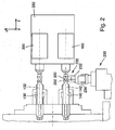
- Fig. 2 is a plan view of the same finishing machine from above in the direction of the direction perpendicular to the z-direction y direction shown.
- Fig. 3 shows an oblique perspective view of some essential components of the same belt finishing machine.
- the belt finishing machine is adapted for machining fixed and variable cam pieces for a camshaft valvetrain. Only the peripheral surfaces of the cams are finished, not the adjacent cylindrical bearing surfaces.
- the finish machining is the last material-removing finishing, so a finishing.
- the finishing machine is located in the material flow behind an upstream grinding machine and in front of a downstream washing system.
- the workpieces 200 to be processed are the finishing machine in the representation shown from the right via a horizontal transport device 205 fed automatically loaded into the finishing machine by means of a handling system and unloaded after completion of a multi-stage processing (brush deburring and subsequent Bandfinishen) and discharged via the transport device 205.
- the band finishing machine is designed as a rotary indexing machine and allows short non-productive times for the workpiece change and thus a high workpiece throughput and short cycle times, so that an economic processing with high quality machining is possible.
- the finishing machine has a rotary table 110, which by means of a rotary drive, not shown, cyclically about a parallel to the z-direction horizontal rotary table axis 112 is rotatable.
- the standing rotary table is rotatably mounted by means of suitable bearings in a vertical support member of the machine frame and can be driven by means of an electromechanical rotary drive or an NC-controlled direct drive.
- Each of the workpiece spindles is rotatable about a spindle axis 122, 132, 142 and 152 wherein the spindle axes parallel to each other and parallel to the rotary table axis 112 extend in the horizontal direction and have the same radial distance from the rotary table axis.
- a separate spindle drive is provided, so that the rotation of each workpiece spindle can be controlled independently of the rotations of other workpiece spindles.
- Each of the workpiece spindles has a workpiece holder with which a single workpiece can be accommodated so that a through the Workpiece receiving recorded workpiece by rotation of the workpiece spindle can be rotated about its workpiece axis.
- the workpiece spindles and the workpiece holders attached to them are identical in each case. Special features of the workpiece holders provided here will be discussed later, especially in connection with Fig. 4 the example of the workpiece holder 160 of the second workpiece spindle 130 explained in detail.
- the rotary table "operates" four work stations arranged in the circumference of the rotary table.
- a loading unit 210 is provided for loading and unloading the workpiece holders.
- the first workpiece spindle 120 is in the loading and unloading position in the working area of the loading unit 210. This grasps a finished workpiece via a gripper system and transports it to the discharge belt of the transport device 205. Thereafter, a premachined workpiece is gripped by the feed belt of the transport device and transported to the workpiece holder of the first workpiece spindle and attached there.
- a 90 ° clockwise rotation of the rotary table then transports the workpiece to be machined into the second work station, which has a brush deburring unit 220.
- a deburring brush 222 which is rotatably mounted at the end of a pivoting arm, the outside of the rotating workpiece can be processed by brush deburring, to remove any burrs still existing after grinding.
- the second workstation is thus a processing station at which a workpiece machining takes place.
- An indexing of the rotary table by 90 ° then brings the deburred workpiece to a further processing station, namely the third workstation in the working area of a first finishing unit 230.
- This is constructed as a belt finishing unit and has two parallel belt conveyors, so that on the workpiece two axially staggered workpiece sections (cams) can be processed simultaneously by means of band finishing.
- the first Finishech is set up in the process exemplified here for processing rotationally symmetric peripheral surfaces of the so-called Nullhubnocken.
- the rotary table is indexed by 90 °, so that the workpiece is finally transported to the fourth workstation in the working area of a second Finishech 240, with which the non-rotationally symmetrical peripheral surfaces of the adjusting cams of the workpiece are processed.
- the second finishing unit is also designed as a twin-tape machine, so that at the same time two adjusting cams offset axially relative to one another can be machined on their circumference by finishing.
- a further rotation of the rotary table by 90 ° brings the in three consecutive machining operations by means of three successively approached processing stations finely machined workpiece again to the first workstation, where it is removed by means of the loading unit 210 from the workpiece holder and transported to the removal.
- the rotary table In order to accurately position the workpiece spindles or the workpieces in a workstation, the rotary table is indexed in the respective rotational positions or angular positions by means of an automatic indexing device and clamped by means of an automatic clamping device. Before the handover, it is released again. These devices are controlled by the machine control.
- a finite (non-continuous) finishing belt is used, the belt ends of which are each attached to a belt reel.
- the fresh, still unused finishing tape is kept on a supply roll and guided over the engagement region on the workpiece (area of the pressure roller) with the aid of belt guiding devices to a driven belt roller which picks up the used finishing belt.
- the tape feed is achieved via a drive of this tape roll, which pulls the tape through the entrance area.
- the reel with the fresh finishing belt acts as a band brake and maintains the belt tension.
- the first finishing unit 230 has two finishing tapes 232, 234 running parallel to one another, which at the same time in each case process the peripheral surface of an adjusting cam of the workpiece 200.
- the workpiece 200 is rotated around its workpiece axis 202 by means of the spindle drive of the third workpiece spindle 140.
- the finishing tapes are pressed by means of a pressure roller 236 with a pressure force acting radially to the workpiece axis to the rotating peripheral surface of the workpiece.
- the pressure roller is on its outer periphery of a hard elastic material with a low compliance, so that Andrückkraftspitzen can be avoided.
- the pressure roller is offset by means of an integrated oscillation device into a short-stroke oscillation movement parallel to the workpiece axis 202 (see double arrow).
- an integrated oscillation device into a short-stroke oscillation movement parallel to the workpiece axis 202 (see double arrow).
- these workpieces are operated with discontinuous tape feed, so that the finishing belt rests during processing and the cutting speed exclusively by the rotational movement of the workpiece in combination with the superimposed axially oscillating relative movement between the workpiece and finishing belt is produced.
- a used finishing belt section is replaced with a fresh finishing belt section by advancing the finishing belt by a predetermined belt advance distance in a processing break with unloaded finishing belt.
- by the continuous or discontinuous supply of fresh, unused finishing tape sections even in large series of workpieces can be achieved well reproducible machining results.
- the second finishing unit 240 is constructed substantially identically.
- the cycle times during machining should be kept as low as possible, so that a workpiece change should be as fast as possible.
- a solution is realized for the workpiece clamping, on the one hand allows a quick workpiece change and on the other hand, a stable against transverse forces coaxial tension of the workpieces.
- the workpiece holder is designed as a passive plug-in receptacle for rotationally fixed receiving a workpiece.
- passive workpiece holders do not require a tensioning drive operable clamping means for clamping the workpiece.
- the workpiece is not clamped radially, but only more or less plugged in the axial direction, non-positively held against falling and secured against rotation. As a result, a quick picking up and removing the workpieces is realized.
- an abutment device for fixing a recorded in a workpiece holder workpiece is provided in a coaxial with the spindle axis of the workpiece spindle machining position, wherein the abutment means engages the workpiece at an axial distance from the workpiece holder when the workpiece spindle is in a processing station belonging to the processing position.
- the tailstock unit 300 is part of a tailstock device 350, which is mounted at an axial distance in the z direction in front of the rotary table and mounted on the front workpiece holders on the machine bed.
- the tailstock device 350 has three identically constructed tailstock units 300, 360, 370, namely one tailstock unit for each of the processing stations 220, 230 and 240.
- the tailstock unit 300 is assigned to the brushing, while the tailstock unit 360 of the first finishing unit and tailstock unit 370 is associated with the second finishing unit.
- the tailstock unit 300 has a tailstock spindle 310 that is passive, i. without its own drive, about a tailstock spindle axis 312 is rotatable and by means of a feed drive parallel to the tailstock axis in the direction of the opposite workpiece holder and movable away from it.
- the tailstock spindle axis is arranged to coincide with the workpiece spindle axis of that workpiece spindle which is in the machining position at the brushing direction, in the example case with the spindle axis 132 of the second workpiece spindle 130.
- the spindle-side workpiece holder 160 is formed as a passive plug-in receptacle for rotationally fixed receiving the workpiece.
- a front end portion of the workpiece holder for this purpose forms a mandrel portion 162 having a cylindrical outer surface which has an outer diameter which is adapted to the inner diameter of the workpiece to be clamped (indicated by dashed lines), that the mandrel portion can be introduced axially into the workpiece to form a clearance fit.
- the workpiece is thus already aligned largely coaxially with the spindle axis.
- a conical centering section 164 adjoins the spindle side with a diameter which increases in size toward the rotary table. A workpiece plugged onto the mandrel section is thereby centered with respect to the spindle axis 132.
- Fig. 4B shows a perpendicular to the spindle axis 132 extending section through the mandrel portion 162 and the elements contained therein of a passive anti-rotation device for securing a recorded workpiece against rotation.
- a driver element 166 is pivotably mounted about an axis of rotation extending parallel to the spindle axis and has a radially outwardly projecting latching lug 165, in the swung-out state of the driver element protrudes through a slot 167 on the circumference of the mandrel portion to the outside.
- a compression spring 168 is arranged, which biases the driver element in this disengaged position. against the force of the compression spring, the driver element can be pressed inwards.
- a workpiece is then pushed onto the mandrel section substantially axially from the front, then it is centered when it comes into contact with the conical centering section 164 with respect to the spindle axis 182.
- the here provided as a workpiece cam pieces have on their inner side an internal toothing for the rotationally fixed coupling to axially adjacent components of the camshaft.
- the locking lug 166 of the driver engages in one of the tooth gaps, so that in the circumferential direction a positive connection between the driver element and the workpiece is formed, whereby this is secured against rotation relative to the mandrel portion.
- the compression spring presses the driver against the inside of the workpiece, wherein the spring force is dimensioned so that the workpiece is secured by this frictional connection against falling from the mandrel portion.
- the axial connector between the workpiece holder and the workpiece can be solved by axial removal of the workpiece during workpiece change in a simple manner.
- the opposite tailstock spindle at its workpiece receiving end facing a conical centering portion 364 which engages the axial feed of the tailstock spindle in the workpiece, whereby the workpiece is centered with respect to the spindle axis 132.
- the workpiece is thus in this embodiment in principle axially between points or between the conical centering sections 164 and 364th tense and is thereby stabilized against the radial machining forces acting on the machining at both ends.
- This type of workpiece clamping between tips in conjunction with a rotary table can of course be provided not only in the workpieces described here by way of example, but is also useful for other workpiece geometries, especially for those workpieces that have a relatively long compared to their diameter, ie protrude relatively far beyond a spindle-side workpiece holder.
- This workpiece clamping between peaks is also possible for massive workpieces, for example by the tailstock has a tip which engages in a front-side central recess of the workpiece.
- an inner cone could also be provided for clamping solid workpieces with cylindrical end sections.
- the schematic Fig. 5 shows a side view of a designed as a band finishing machine finishing machine 500 according to a second embodiment in a direction parallel to the z-direction of the machine-fixed machine coordinate system MKS.
- the finishing machine is designed in the example for the same workpieces (cam pieces) and arranged in the material flow in line behind an upstream grinding machine and before a downstream washer.
- the workpieces 200 to be processed are fed to the finishing machine in the illustration shown from the right via a horizontal transport device 605, automatically loaded into the finishing machine with the aid of a handling system (loading device 610) and unloaded again after completion of a strip finishing operation and conveyed off to the left.
- a handling system loading device 610
- two finishing units 620, 630 acting simultaneously on the workpiece are provided.
- the finishing machine has a rotary table 510, which by means of a rotary drive, not shown, cyclically about a parallel to the z-direction horizontal rotary table axis 112 is rotatable.
- two diametrically opposed workpiece spindles are arranged radially outside the rotary table axis 512, namely a first workpiece spindle 520 rotatable about a first spindle axis 522 and a second workpiece spindle 530 rotatable about a second spindle axis 532.
- the spindle axes lie parallel to one another and parallel to the rotary table axis 512 in horizontal Direction.
- a separate spindle drive is provided so that the rotation of each workpiece spindle can be controlled independently of the rotations of the other workpiece spindle.
- the workpiece spindles and the workpiece holders attached to them are identical in each case.
- the workpiece holders are designed as collets, which are actuated by their own clamping drives and hold the clamped workpiece by clamping torque-proof and center.
- the rotary table "operates" two work stations arranged on the circumference of the rotary table.
- the loading unit 610 is provided for loading and unloading the workpiece holders.
- the situation shown is the first workpiece spindle 520 in the loading and unloading in the working area of the loading unit 610.
- the loading is done from the right, the removal to the left.
- the processing station has two substantially identical finishing units 620, 630 which engage diametrically opposite sides of the workpiece.
- the finishing units can each be moved horizontally parallel to the x-axis. Furthermore, a linear axis is provided in the z-direction for the axial positioning of the finishing units on the workpiece.
- Both the first finisher unit 620 and the second finisher unit 630 are constructed as a belt finisher and have two parallel belt conveyors, so that two axially staggered workpiece sections (cams) can be simultaneously machined on the workpiece by belt finishing.
- the first Finishech is set for processing axially offset from each other first cam, while the second Finisometer machined axially to the first cam offset second cam.
- a finite (non-continuous) finishing belt is used, the belt ends of which are each fastened to a belt reel. It is worked with slow continuous or discontinuous tape feed.
- the rotary table is indexed 180 °. This rotation brings the finished workpiece back to the first workstation, where it is removed by means of the loading unit 610 from the workpiece holder and transported for removal.
- the workpieces are here only one-sided (in the workpiece holder) and not stretched between peaks and there are no corresponding tailstock facilities. Nevertheless, even with large radial pressure forces during finishing a stabilized against transverse forces, the workpiece spindle coaxial workpiece rotation is ensured.
- the arrangement of the finishing units is chosen such that the pressure forces acting radially to the workpiece axis the first and second Finishech are aligned substantially symmetrically to the workpiece axis. As a result, the pressure forces applied by the finishing units during machining compensate each other, so that processing stabilized against transverse forces is possible.
- Each Finishech acts as a support or counter-bearing for receiving the respective lateral forces introduced by the other Finishquip.
- a finishing machine 800 which in example is adapted for machining relatively long workpieces 805 in the form of crankshafts.
- the processing means include several finishing units which can simultaneously handle both main bearings and crank bearings of the crankshaft by means of band finishing on a crankshaft held in a machining position.
- the workpiece clamping devices can simultaneously clamp four crankshafts each between points and move them in cycles to different workstations.
- two coaxial rotatable rotary tables are provided, one of which belongs to a headstock unit and four separately driven workpiece spindles and the other belongs to a tailstock unit which serves as an abutment means for fixing the workpieces in a coaxial with the spindle axis of the workpiece spindles aligned machining position.
- the headstock unit includes a first rotary table 810, which can be cyclically rotated about its horizontal rotary table axis 812 by means of an electric first rotary drive 814.
- the first rotary table is mounted in a vertical support element which is mounted fixed in the axial direction on the machine bed 802 of the finishing machine.
- four workpiece spindles are radially outside of Round table arranged, of which only two workpiece spindles 820, 830 can be seen in the side view.
- To each of the workpiece spindles belongs an independently controllable from the other rotary actuators rotary drive, which can rotate the workpiece spindle to the associated spindle axis 822, 832.
- the four integrated in the headstock rotary axis workpiece spindles are each equipped with an axially sprung tip 824, 834 and drivers, which ensure that the clamped workpieces are taken in rotation in the circumferential direction of the respective workpiece spindle and taken along.
- the first rotary table 810 is rotated about its horizontal rotary table axis 812 and indexed to a four discrete positions associated with four workstations of the finishing machine.
- the upper workpiece spindle 820 is in the loading and unloading position in the working area of a loading unit, not shown.
- a fixedly mounted pneumatic actuator 860 acts as an actuator to retract the tip of the workpiece tip located in the loading and unloading position.
- a second rotary table 910 Viewed in the axial direction relative to the first rotary table 810, a second rotary table 910 is arranged, which is part of the tailstock unit.
- the second rotary table can be rotated by means of an electric second rotary drive 914 about its horizontal rotary table axis 912, which is coaxial with the axis of rotation or rotary table axis 812 of the first rotary table.
- the first and the second rotary drive can be controlled independently of one another via the machine control. This can ensure a synchronous rotation of the rotary tables with control technology. This concept is also referred to here as a "twin drive".
- the common axis of rotation forms the symmetry axis of the arrangement.
- the second rotary table 910 is axially movable for the conversion operation, ie, parallel to the symmetry axis of the arrangement.
- the rotary table is mounted for this purpose in a vertical support member which on a carriage 970 is mounted, which is axially displaceably guided on axial guide rails and can be reciprocated horizontally by means of a NC-axis 975 with ball screw.
- the second rotary table 910 carries four identical tailstock spindles in 90 ° angle division, of which only two tailstock spindles 920 and 930 are shown.
- Each of the tailstock spindles has a passively rotatable, roller bearing, spring loaded tip 924, 934 so that each one long workpiece can be clamped spring loaded between the tips of the opposing workpiece spindle and the associated tailstock spindle.
- the rotary table is indexed at four discrete positions corresponding to the workstations of the finishing machine.
- a stationary pneumatic drive 960 is provided for retracting the tailstock-side tip.
- a workpiece to be machined is clamped in the region of the loading and unloading position by first moving a free workpiece spindle and an associated free tailstock spindle into the working position belonging to the loading and unloading station.
- the workpiece is then gripped by means of a gripper unit and held between the tips, which are retracted by the pneumatic drives against the force of the respective associated return springs.
- the drives are deactivated, so that the workpiece is clamped axially between the tips under the force of the springs belonging to the tips.
- the workpiece can then be moved by synchronous rotation of the two rotary tables 810, 910 by means of synchronized control of the first and second rotary drive in a first processing station and then optionally up to two other processing stations before it is conveyed back to the loading and unloading. Different directions of rotation are possible. In the processing stations, different machining operations on the workpiece be performed.
- the workpieces each remain clamped between clamps from the clamping to the subsequent clamping and can be rotated at the respective workstations by means of the workpiece spindle about its longitudinal axis.
- the counter-bearing second rotary table 910 includes the passive workpiece abutments (eg tip, bezel) driven by the workpiece rotation induced on the opposite main drive side and the workpieces (in the case of an inter-tip solution) by a constant clamping force (eg Spring force) in the other five degrees of freedom between the tips fixed.
- This clamping force can be released by an external workpiece removal operation (e.g., stationarily located at the loading / unloading station).
- Step proportion of moment of inertia is provided in the twin drive that the second rotary table is not passively taken over the first round table 810, but has its own rotary drive (second rotary drive 914), which is advantageously a servo-controlled rotary drive (NC axis).
- This embodiment provides advantages in terms of geometric Accuracy and the drive dynamics achieved: Firstly, angular offsets between two rotary tables can be virtually eliminated by interrogation and comparison of the two-sided angle encoder systems of the rotary actuators, so that always (regardless of the dimensions of the arrangement) a synchronous rotation of the round tables is ensured.
- the rotary tables are on the machine side only via the machine control, but not mechanically coupled. Inevitable compliances that might occur with mechanical coupling of the rotary tables are eliminated.
- the execution of the twin drive due to the inertia issue described the dynamics and energy consumption compared to a passive entrainment of the second rotary table significantly improve.
- the arrangement allows maximum productivity even when machining axially long workpieces.
- the transverse forces acting radially on the workpieces during machining are reliably absorbed by the workpiece clamping between coaxial tips.
- only a single Finishech is provided in addition to a loading and unloading unit. It is also possible to provide more than two finishing units, for example three or four finishing units. These can be set up for similar or different finishing operations. In the embodiments shown, all machining operations are performed on the rotating workpiece, wherein it is not important for the machining to fix the workpiece in a certain rotational position.
- the workpiece spindles can therefore have a relatively simple structure without means for setting and fixing a specific rotational position.
- the equipped with workpiece spindles rotary table is rotatable in the embodiments about a horizontal rotary table axis.
- a horizontal, lying rotary table which is rotatable about a vertical rotary table axis.
- the axes of Finishechen and optionally other processing units are orientable differently.
- the workpiece spindles mounted on the rotary table rotate axially parallel to the rotary table.
- the spindle axes in workpiece spindles can also be aligned transversely, in particular perpendicularly to the rotary table axis, for example radially to the rotary table axis, so that a uniform or non-uniform star-shaped arrangement of the workpiece spindles results.
- This application discloses, inter alia, a workpiece holding device with two coaxially rotatable rotary tables, wherein the first rotary table carries the (via a spindle drive rotatable about a spindle axis) workpiece spindles and the opposite second rotary table has means for abutment of the workpieces.
- These devices for abutment can be designed for example as tailstock spindles, but possibly also have other design.
- Such a workpiece holding device can be used independently of the other features of the claimed invention also in processing machines without finishing units to support workpieces, in particular relatively long workpieces, during machining against transverse forces, which are exerted by a machining tool on the possibly rotating workpiece.
Landscapes
- Engineering & Computer Science (AREA)
- Mechanical Engineering (AREA)
- Grinding And Polishing Of Tertiary Curved Surfaces And Surfaces With Complex Shapes (AREA)
- Constituent Portions Of Griding Lathes, Driving, Sensing And Control (AREA)
- Grinding Of Cylindrical And Plane Surfaces (AREA)
Claims (15)
- Machine de finition (100) pour le traitement de finition de surfaces courbes de pièces à usiner sur des pièces à usiner (200) avec :au moins une broche de pièce à usiner pouvant tourner autour d'un axe de broche à l'aide d'un entraînement de broche et comportant un logement de pièce à usiner pour loger une pièce à usiner de telle sorte que la pièce à usiner reçue par le logement de pièce à usiner peut tourner, par rotation de la broche de pièce à usiner, autour d'un axe de pièce à usiner ;au moins une unité de finition comportant un dispositif de pression pour presser un outil de traitement équipé d'un moyen de découpe au niveau d'une surface périphérique incurvée de la pièce à usiner avec une force de pression orientée dans le plan radial par rapport à l'axe de pièce à usiner ; etune table ronde (110) pouvant être tournée selon un certain tempo autour d'un axe de table ronde (112), plusieurs broches de pièce à usiner (120, 130, 140, 150) étant disposées au niveau de la table ronde avec un écart angulaire prédéfini et une pièce à usiner reçue par un logement de pièce à usiner pouvant être déplacée dans une position de traitement au niveau de l'unité de finition par rotation de la table ronde et pouvant être transportée à la fin du traitement de finition hors de cette position de traitement jusqu'à une station de travail suivante ;caractérisée par un dispositif de maintien actif de la pièce à usiner à l'encontre des forces transversales au niveau d'au moins une section de pièce à usiner reposant à une certaine distance axiale du logement de pièce à usiner.
- Machine de finition selon la revendication 1, caractérisée en ce que la table ronde peut être indexée dans chaque position angulaire appartenant à une position de traitement au moyen d'un dispositif d'indexation et/ou peut être serrée fixement au moyen d'un dispositif de serrage.
- Machine de finition selon la revendication 1 ou 2, caractérisée par un dispositif de contre-palier s'engrenant avec la pièce à usiner à une certaine distance axiale du logement de pièce à usiner pour fixer la pièce à usiner dans une position de traitement orientée dans le plan coaxial par rapport à l'axe de broche de la broche de pièce à usiner lorsque la broche de pièce à usiner se trouve dans une position de traitement appartenant à une station de traitement.
- Machine de finition selon l'une quelconque des revendications précédentes, la machine de finition étant conçue de telle sorte qu'une pièce à usiner peut être reçue, au niveau d'au moins une station de traitement, avec ses extrémités axiales entre les pointes agissant de façon à exercer un centrage.
- Machine de finition selon l'une quelconque des revendications précédentes, caractérisée par un dispositif de contrepoupée (350) avec au moins une unité de contrepoupée (300, 360, 370) comportant une broche de contrepoupée pouvant tourner autour d'un axe de broche de contrepoupée et évoluant de préférence parallèlement à l'axe de broche de contrepoupée, une broche de contrepoupée propre étant prévue de préférence pour chaque station de traitement prévue pour un traitement de pièce à usiner.
- Machine de finition selon l'une quelconque des revendications précédentes, caractérisée en ce qu'une table ronde (910) supplémentaire est prévue en sus de la table ronde (810) supportant les broches de pièce à usiner (820, 830), ladite table supplémentaire pouvant tourner dans le plan coaxial avec la table ronde supportant les broches de pièce à usiner et supportant au moins un dispositif de contrepalier, notamment une broche de contrepoupée (920, 930), une broche de contrepoupée propre étant de préférence prévue pour chaque broche de pièce à usiner.
- Machine de finition selon la revendication 6, caractérisée en ce qu'un entraînement en rotation (814, 914) propre est associé à chacune des deux tables rondes (810, 910), une rotation synchrone des tables rondes (810, 910) pouvant être atteinte par synchronisation d'entraînements en rotation via une commande de machine de la machine de finition et/ou caractérisée en ce que la table ronde (910) supplémentaire peut être avancée parallèlement à son axe de rotation (912), en direction de la table ronde (810) supportant les broches de pièce à usiner ou dans la direction contraire.
- Machine de finition selon l'une quelconque des revendications précédentes, caractérisée par plusieurs unités de traitement (220, 230, 240) associées à la table ronde pour mettre en oeuvre des opérations de traitement au niveau d'une pièce à usiner reçue à travers un logement de pièce à usiner, au moins une des unités de traitement étant une unité de finition (230, 240), de préférence au moins une unité de traitement étant configurée pour une autre opération de traitement, notamment d'ébavurage.
- Machine de finition selon l'une quelconque des revendications précédentes, dans laquelle la machine de finition comporte plusieurs unités de finition (230, 240, 620, 630) commandées par la même table ronde (110), notamment précisément deux unités de finition (230, 240, 620, 630) disposées de préférence de telle sorte qu'elles étaient commandées les unes après les autres à partir de la table ronde.
- Machine de finition selon l'une quelconque des revendications précédentes, dans laquelle la station de traitement de la machine de finition comporte deux unités de finition (620, 630) conçues pour traiter simultanément la même pièce à usiner positionnée dans une position de traitement appartenant à la station de traitement et/ou dans laquelle une première unité de finition (620) et au moins une deuxième unité de finition (630) étant prévue au niveau d'une station de traitement pour le traitement de finition s'engrenant, en cas de traitement, simultanément avec la pièce à usiner de telle sorte que les forces de pression s'engrenant dans le plan radial par rapport à l'axe de pièce à usiner de la première et de la deuxième unité de finition sont orientées pour l'essentiel symétriquement à l'axe de pièce à usiner, deux unités de finition (620, 630) pour l'essentiel identiques de façon diamétralement opposée étant prévues de préférence au niveau d'une station de traitement, pour le traitement de finition.
- Machine de finition selon l'une quelconque des revendications précédentes, dans laquelle le logement de pièce à usiner (160) est réalisé sous la forme d'un logement d'enfichage passif, au moins un ressort de maintien et/ou au moins un élément de maintien (166) sollicité par ressort comportant de préférence le logement de pièce à usiner (160), pour maintenir par complémentarité de frottements la pièce à usiner enfichée sur le logement de pièce à usiner ou s'enfichant dans le logement de pièce à usiner et pour la protéger contre la chute.
- Machine de finition selon l'une quelconque des revendications précédentes, dans laquelle le logement de pièce à usiner est conçu pour un logement solidaire en rotation d'une pièce à usiner, le logement de pièce à usiner comportant de préférence un dispositif de sécurité antitorsion passif pour sécuriser contre la torsion une pièce à usiner reçue, le logement de pièce à usiner comportant de préférence un élément de doigt d'entraînement (166) sollicité s'engrenant par complémentarité de formes en cas de logement d'une pièce à usiner dans un évidement au niveau de la pièce à usiner dans la direction circonférentielle et/ou dans laquelle le logement de pièce à usiner (160) comporte une section de centrage (164) conique pour le centrage de la pièce à usiner par rapport à l'axe de broche (132).
- Machine de finition selon l'une quelconque des revendications précédentes, dans laquelle les broches de pièce à usiner (120, 130, 140, 150) sont placées au niveau de la table ronde (110) de telle sorte que les axes de broche (122, 132, 142, 152) s'étendent parallèlement à l'axe de table ronde (112).
- Machine de finition selon l'une quelconque des revendications précédentes, dans laquelle l'unité de finition (230, 240) comporte un dispositif d'oscillation pour produire un mouvement d'oscillation de l'outil de traitement parallèlement à l'axe de pièce à usiner.
- Machine de finition selon l'une quelconque des revendications précédentes, dans laquelle au moins une unité de finition (230, 240) est une unité de finition de bande.
Applications Claiming Priority (2)
| Application Number | Priority Date | Filing Date | Title |
|---|---|---|---|
| DE102011081918A DE102011081918A1 (de) | 2011-08-31 | 2011-08-31 | Finishmaschine zur Finishbearbeitung gekrümmter Werkstückoberflächen an Werkstücken |
| PCT/EP2012/066687 WO2013030194A1 (fr) | 2011-08-31 | 2012-08-28 | Machine de finition de surfaces courbes de pièces à usiner |
Publications (3)
| Publication Number | Publication Date |
|---|---|
| EP2750829A1 EP2750829A1 (fr) | 2014-07-09 |
| EP2750829B1 true EP2750829B1 (fr) | 2016-04-20 |
| EP2750829B2 EP2750829B2 (fr) | 2020-01-01 |
Family
ID=46750343
Family Applications (1)
| Application Number | Title | Priority Date | Filing Date |
|---|---|---|---|
| EP12751076.6A Not-in-force EP2750829B2 (fr) | 2011-08-31 | 2012-08-28 | Machine de finition de surfaces courbes de pièces à usiner |
Country Status (4)
| Country | Link |
|---|---|
| EP (1) | EP2750829B2 (fr) |
| CN (1) | CN104039503B (fr) |
| DE (1) | DE102011081918A1 (fr) |
| WO (1) | WO2013030194A1 (fr) |
Families Citing this family (13)
| Publication number | Priority date | Publication date | Assignee | Title |
|---|---|---|---|---|
| CN103753393A (zh) * | 2014-01-28 | 2014-04-30 | 瓦房店金北轴承制造有限公司 | 一种轴承超精机消除支点印的润滑支点 |
| CN104924183A (zh) * | 2015-05-06 | 2015-09-23 | 广西北流市红日紫砂陶瓷厂 | 灯头磨边机 |
| CN104907916A (zh) * | 2015-05-29 | 2015-09-16 | 洛阳市西工区华科精密机械厂 | 一种外径超精机的传动机构 |
| DE102015216357A1 (de) * | 2015-08-27 | 2017-03-02 | Supfina Grieshaber Gmbh & Co. Kg | Umfangsflächenbearbeitungseinheit, Werkzeugmaschine und Verfahren zum Betrieb |
| DE102016103105A1 (de) | 2016-02-23 | 2017-08-24 | Supfina Grieshaber Gmbh & Co. Kg | Finishvorrichtung |
| CN107283273B (zh) * | 2016-04-06 | 2023-08-01 | 天通日进精密技术有限公司 | 晶棒加工设备及用于该设备的主轴机构与晶棒加工方法 |
| DE102016107965A1 (de) * | 2016-04-29 | 2017-11-02 | Supfina Grieshaber Gmbh & Co. Kg | Bandfinishvorrichtung |
| DE102016116161A1 (de) * | 2016-08-30 | 2018-03-01 | Supfina Grieshaber Gmbh & Co. Kg | Werkzeugmaschine und Verfahren zur finishenden Bearbeitung von Werkstücken |
| CN106625087B (zh) * | 2016-10-18 | 2018-11-23 | 江南大学 | 一种多形变铸件修磨装置的打磨机构 |
| CN107297666B (zh) * | 2017-08-14 | 2023-08-08 | 上海新孚美变速箱技术服务有限公司 | 一种用于汽车无级变速箱再制造的锥形盘修复总成系统 |
| DE102019124660B3 (de) * | 2019-09-13 | 2021-01-28 | Supfina Grieshaber Gmbh & Co. Kg | Finishbearbeitungssystem und Verfahren zum Betrieb eines Finishbearbeitungssystems |
| CN117428680B (zh) * | 2023-12-06 | 2024-06-04 | 丹阳丹金航空材料科技有限公司 | 一种导弹弹翼加工模具 |
| CN118080984B (zh) * | 2024-03-26 | 2024-09-06 | 青岛高逸汽车零部件有限公司 | 一种制动软管接头上料刻字一体机 |
Citations (7)
| Publication number | Priority date | Publication date | Assignee | Title |
|---|---|---|---|---|
| DE19607778C2 (de) | 1996-03-01 | 2001-10-11 | Nagel Masch Werkzeug | Vorrichtung zur Finish-Bearbeitung, insbesondere von Kurbel- oder Nockenwellen |
| DE10016897A1 (de) | 2000-04-05 | 2001-10-18 | Supfina Grieshaber Gmbh & Co | Mehrfachbearbeitung eines Werkstücks in einer Aufspannung |
| EP1506839A1 (fr) | 2003-08-15 | 2005-02-16 | Supfina Grieshaber GmbH & Co. KG | Outil de finition |
| EP1518643A1 (fr) | 2003-09-16 | 2005-03-30 | Supfina Grieshaber GmbH & Co. KG | Dispositif de finition |
| EP1741514B1 (fr) | 2005-07-07 | 2008-03-19 | Supfina Grieshaber GmbH & Co. KG | Dispositif pour meuler et/ou finir une pièce |
| DE102007051047A1 (de) | 2007-10-16 | 2009-04-23 | Nagel Maschinen- Und Werkzeugfabrik Gmbh | Andrückeinrichtung für Schneidmittel sowie Vorrichtung und Verfahren zur Finishbearbeitung von Umfangsflächen an zylindrischen Werkstückabschnitten |
| DE102010060471A1 (de) | 2010-10-07 | 2012-04-12 | Thielenhaus Technologies Gmbh | Maschine zur Finishbearbeitung von Werkstücken, insbesondere langen Werkstücken |
Family Cites Families (10)
| Publication number | Priority date | Publication date | Assignee | Title |
|---|---|---|---|---|
| US2772527A (en) * | 1953-09-21 | 1956-12-04 | Roy A Farnam | Coupler for crank shaft grinder |
| JPS5343294A (en) * | 1976-09-30 | 1978-04-19 | Toyoda Mach Works Ltd | Phase indexing device |
| DE19925077A1 (de) | 1999-05-15 | 2000-11-23 | Supfina Grieshaber Gmbh & Co | Vorrichtung zum Bandfinishen von gekrümmten Werkstückoberflächen |
| DE10160280B4 (de) * | 2001-12-07 | 2011-05-26 | Thielenhaus Technologies Gmbh | Vorrichtung zur mechanischen Oberflächenbearbeitung von Werkstücken |
| DE10342139B4 (de) | 2003-09-12 | 2008-06-19 | Thielenhaus Technologies Gmbh | Verfahren zur Finishbearbeitung von Umfangsflächen an wellenförmigen Werkstücken |
| DE10342134B4 (de) | 2003-09-12 | 2009-09-03 | Thielenhaus Technologies Gmbh | Verfahren und Vorrichtung zur Finishbearbeitung von Kurbel- und Nockenwellen |
| US7785173B2 (en) * | 2005-07-05 | 2010-08-31 | Supfina Machine Co. | Superfinishing machine and method |
| DE102007050482B4 (de) * | 2007-10-19 | 2017-08-24 | Thielenhaus Technologies Gmbh | Verfahren und Vorrichtung zur Finishbearbeitung |
| CN201559073U (zh) * | 2009-11-19 | 2010-08-25 | 天润曲轴股份有限公司 | 曲轴自动分度压紧装置 |
| CN102069396A (zh) * | 2009-11-23 | 2011-05-25 | 天润曲轴股份有限公司 | 一种滚压曲轴圆角快速装夹支架 |
-
2011
- 2011-08-31 DE DE102011081918A patent/DE102011081918A1/de not_active Ceased
-
2012
- 2012-08-28 CN CN201280052951.2A patent/CN104039503B/zh not_active Expired - Fee Related
- 2012-08-28 WO PCT/EP2012/066687 patent/WO2013030194A1/fr not_active Ceased
- 2012-08-28 EP EP12751076.6A patent/EP2750829B2/fr not_active Not-in-force
Patent Citations (7)
| Publication number | Priority date | Publication date | Assignee | Title |
|---|---|---|---|---|
| DE19607778C2 (de) | 1996-03-01 | 2001-10-11 | Nagel Masch Werkzeug | Vorrichtung zur Finish-Bearbeitung, insbesondere von Kurbel- oder Nockenwellen |
| DE10016897A1 (de) | 2000-04-05 | 2001-10-18 | Supfina Grieshaber Gmbh & Co | Mehrfachbearbeitung eines Werkstücks in einer Aufspannung |
| EP1506839A1 (fr) | 2003-08-15 | 2005-02-16 | Supfina Grieshaber GmbH & Co. KG | Outil de finition |
| EP1518643A1 (fr) | 2003-09-16 | 2005-03-30 | Supfina Grieshaber GmbH & Co. KG | Dispositif de finition |
| EP1741514B1 (fr) | 2005-07-07 | 2008-03-19 | Supfina Grieshaber GmbH & Co. KG | Dispositif pour meuler et/ou finir une pièce |
| DE102007051047A1 (de) | 2007-10-16 | 2009-04-23 | Nagel Maschinen- Und Werkzeugfabrik Gmbh | Andrückeinrichtung für Schneidmittel sowie Vorrichtung und Verfahren zur Finishbearbeitung von Umfangsflächen an zylindrischen Werkstückabschnitten |
| DE102010060471A1 (de) | 2010-10-07 | 2012-04-12 | Thielenhaus Technologies Gmbh | Maschine zur Finishbearbeitung von Werkstücken, insbesondere langen Werkstücken |
Non-Patent Citations (3)
| Title |
|---|
| GÜNTER SPUR: "Handbuch der Fertigungstechnik. Band 5", 1986, CARL HANSER, ISBN: 3-446-12536-1, pages: 538 - 539, XP055346232 |
| JOHANNES KUNSEMÜLLER: "Meyers Lexikon der Technik und der exakten Naturwissenschaften", 1970, BI, article "Lünette", XP055346780 |
| SUPFINA GRIESHABER: "Superfinish-Technologie", 2001, VERLAG MODERN, ISBN: 3-478-93253-X, pages: 10-11,24 - 33, XP055346162 |
Also Published As
| Publication number | Publication date |
|---|---|
| WO2013030194A1 (fr) | 2013-03-07 |
| CN104039503B (zh) | 2017-08-15 |
| DE102011081918A1 (de) | 2013-02-28 |
| EP2750829A1 (fr) | 2014-07-09 |
| EP2750829B2 (fr) | 2020-01-01 |
| CN104039503A (zh) | 2014-09-10 |
Similar Documents
| Publication | Publication Date | Title |
|---|---|---|
| EP2750829B1 (fr) | Machine de finition de surfaces courbes de pièces à usiner | |
| DE112013000293B4 (de) | Drehbearbeitungsmaschine und Drehbearbeitungsverfahren | |
| EP1984145B1 (fr) | Procede de meulage de pieces en forme de barreau, meuleuse permettant de mettre en oeuvre le procede et cellule double de meulage | |
| DE102008009124B4 (de) | Verfahren zum Schleifen von stabförmigen Werkstücken und Schleifmaschine | |
| DE19753797C2 (de) | Vorrichtung zum Schleifen von Werkstücken | |
| DE102016117915B4 (de) | Spindelmodul für eine Werkstückbearbeitungsvorrichtung | |
| DE102015010942B4 (de) | Verfahren und Vorrichtung zur Schleif- und Feinstbearbeitung | |
| EP2162260A1 (fr) | Procédé et dispositif de meulage de cames d'un arbre à cames | |
| DE102011118747B4 (de) | Verfahren und Werkzeugmaschine zur Komplettbearbeitung wellenförmiger Werkstücke | |
| EP1330338A1 (fr) | Machine polyvalente | |
| DE10016897B4 (de) | Vorrichtung zum Bearbeiten von Werkstücken mit mindestens zwei Bearbeitungsstationen | |
| EP0967038B1 (fr) | Dispositif d' usinage de pièces par enlèvement de matière | |
| DE4107462C2 (de) | Werkzeugmaschine zur spanabhebenden Bearbeitung von Werkstücken | |
| DE10307977B4 (de) | Verfahren und Vorrichtung zur Bearbeitung von Ausgleichsgehäusen | |
| CH699901B1 (de) | Vorrichtung zum spanabhebenden Bearbeiten von Werkstücken. | |
| WO2004069472A1 (fr) | Dispositif et procede de rectification commandee par ordinateur d'arbres a cames, de vilebrequins et d'elements similaires | |
| DE102019124660B3 (de) | Finishbearbeitungssystem und Verfahren zum Betrieb eines Finishbearbeitungssystems | |
| DE102010060471B4 (de) | Maschine zur Finishbearbeitung von langen, wellenförmigen Werkstücken | |
| DE102005015649B4 (de) | Verfahren zum Drehen und Feinstbearbeiten eines Werkstückes und Vorrichtung zur Durchführung des Verfahrens | |
| DE112013000290B4 (de) | Drehbearbeitungsmaschine | |
| WO2023052421A1 (fr) | Procédé et dispositif de meulage d'une pièce allongée | |
| EP2206569B1 (fr) | Procédé de fabrication de plusieurs pièces usinées à partir d'une ébauche | |
| DE102012104431A1 (de) | Bearbeitungsvorrichtung und Verfahren hierzu | |
| DE102015205350A1 (de) | Vorrichtung und Verfahren zur spanenden Bearbeitung eines Werkstücks | |
| DE69935647T2 (de) | Vereinfachte rotationssymmetrische werkstücke bearbeitungsmaschine, insbesondere kurbelwellen und arbeitsverfahren solch einer maschine |
Legal Events
| Date | Code | Title | Description |
|---|---|---|---|
| PUAI | Public reference made under article 153(3) epc to a published international application that has entered the european phase |
Free format text: ORIGINAL CODE: 0009012 |
|
| 17P | Request for examination filed |
Effective date: 20140307 |
|
| AK | Designated contracting states |
Kind code of ref document: A1 Designated state(s): AL AT BE BG CH CY CZ DE DK EE ES FI FR GB GR HR HU IE IS IT LI LT LU LV MC MK MT NL NO PL PT RO RS SE SI SK SM TR |
|
| DAX | Request for extension of the european patent (deleted) | ||
| 17Q | First examination report despatched |
Effective date: 20141223 |
|
| GRAP | Despatch of communication of intention to grant a patent |
Free format text: ORIGINAL CODE: EPIDOSNIGR1 |
|
| INTG | Intention to grant announced |
Effective date: 20151116 |
|
| GRAS | Grant fee paid |
Free format text: ORIGINAL CODE: EPIDOSNIGR3 |
|
| GRAA | (expected) grant |
Free format text: ORIGINAL CODE: 0009210 |
|
| AK | Designated contracting states |
Kind code of ref document: B1 Designated state(s): AL AT BE BG CH CY CZ DE DK EE ES FI FR GB GR HR HU IE IS IT LI LT LU LV MC MK MT NL NO PL PT RO RS SE SI SK SM TR |
|
| REG | Reference to a national code |
Ref country code: GB Ref legal event code: FG4D Free format text: NOT ENGLISH |
|
| REG | Reference to a national code |
Ref country code: CH Ref legal event code: EP |
|
| REG | Reference to a national code |
Ref country code: AT Ref legal event code: REF Ref document number: 791865 Country of ref document: AT Kind code of ref document: T Effective date: 20160515 |
|
| REG | Reference to a national code |
Ref country code: IE Ref legal event code: FG4D Free format text: LANGUAGE OF EP DOCUMENT: GERMAN |
|
| REG | Reference to a national code |
Ref country code: DE Ref legal event code: R096 Ref document number: 502012006819 Country of ref document: DE |
|
| REG | Reference to a national code |
Ref country code: LT Ref legal event code: MG4D |
|
| REG | Reference to a national code |
Ref country code: NL Ref legal event code: MP Effective date: 20160420 |
|
| PG25 | Lapsed in a contracting state [announced via postgrant information from national office to epo] |
Ref country code: NO Free format text: LAPSE BECAUSE OF FAILURE TO SUBMIT A TRANSLATION OF THE DESCRIPTION OR TO PAY THE FEE WITHIN THE PRESCRIBED TIME-LIMIT Effective date: 20160720 Ref country code: PL Free format text: LAPSE BECAUSE OF FAILURE TO SUBMIT A TRANSLATION OF THE DESCRIPTION OR TO PAY THE FEE WITHIN THE PRESCRIBED TIME-LIMIT Effective date: 20160420 Ref country code: FI Free format text: LAPSE BECAUSE OF FAILURE TO SUBMIT A TRANSLATION OF THE DESCRIPTION OR TO PAY THE FEE WITHIN THE PRESCRIBED TIME-LIMIT Effective date: 20160420 Ref country code: LT Free format text: LAPSE BECAUSE OF FAILURE TO SUBMIT A TRANSLATION OF THE DESCRIPTION OR TO PAY THE FEE WITHIN THE PRESCRIBED TIME-LIMIT Effective date: 20160420 Ref country code: NL Free format text: LAPSE BECAUSE OF FAILURE TO SUBMIT A TRANSLATION OF THE DESCRIPTION OR TO PAY THE FEE WITHIN THE PRESCRIBED TIME-LIMIT Effective date: 20160420 |
|
| PG25 | Lapsed in a contracting state [announced via postgrant information from national office to epo] |
Ref country code: ES Free format text: LAPSE BECAUSE OF FAILURE TO SUBMIT A TRANSLATION OF THE DESCRIPTION OR TO PAY THE FEE WITHIN THE PRESCRIBED TIME-LIMIT Effective date: 20160420 Ref country code: PT Free format text: LAPSE BECAUSE OF FAILURE TO SUBMIT A TRANSLATION OF THE DESCRIPTION OR TO PAY THE FEE WITHIN THE PRESCRIBED TIME-LIMIT Effective date: 20160822 Ref country code: RS Free format text: LAPSE BECAUSE OF FAILURE TO SUBMIT A TRANSLATION OF THE DESCRIPTION OR TO PAY THE FEE WITHIN THE PRESCRIBED TIME-LIMIT Effective date: 20160420 Ref country code: GR Free format text: LAPSE BECAUSE OF FAILURE TO SUBMIT A TRANSLATION OF THE DESCRIPTION OR TO PAY THE FEE WITHIN THE PRESCRIBED TIME-LIMIT Effective date: 20160721 Ref country code: SE Free format text: LAPSE BECAUSE OF FAILURE TO SUBMIT A TRANSLATION OF THE DESCRIPTION OR TO PAY THE FEE WITHIN THE PRESCRIBED TIME-LIMIT Effective date: 20160420 Ref country code: HR Free format text: LAPSE BECAUSE OF FAILURE TO SUBMIT A TRANSLATION OF THE DESCRIPTION OR TO PAY THE FEE WITHIN THE PRESCRIBED TIME-LIMIT Effective date: 20160420 Ref country code: LV Free format text: LAPSE BECAUSE OF FAILURE TO SUBMIT A TRANSLATION OF THE DESCRIPTION OR TO PAY THE FEE WITHIN THE PRESCRIBED TIME-LIMIT Effective date: 20160420 |
|
| PG25 | Lapsed in a contracting state [announced via postgrant information from national office to epo] |
Ref country code: BE Free format text: LAPSE BECAUSE OF NON-PAYMENT OF DUE FEES Effective date: 20160831 Ref country code: IT Free format text: LAPSE BECAUSE OF FAILURE TO SUBMIT A TRANSLATION OF THE DESCRIPTION OR TO PAY THE FEE WITHIN THE PRESCRIBED TIME-LIMIT Effective date: 20160420 |
|
| REG | Reference to a national code |
Ref country code: DE Ref legal event code: R026 Ref document number: 502012006819 Country of ref document: DE |
|
| PLBI | Opposition filed |
Free format text: ORIGINAL CODE: 0009260 |
|
| PG25 | Lapsed in a contracting state [announced via postgrant information from national office to epo] |
Ref country code: EE Free format text: LAPSE BECAUSE OF FAILURE TO SUBMIT A TRANSLATION OF THE DESCRIPTION OR TO PAY THE FEE WITHIN THE PRESCRIBED TIME-LIMIT Effective date: 20160420 Ref country code: RO Free format text: LAPSE BECAUSE OF FAILURE TO SUBMIT A TRANSLATION OF THE DESCRIPTION OR TO PAY THE FEE WITHIN THE PRESCRIBED TIME-LIMIT Effective date: 20160420 Ref country code: DK Free format text: LAPSE BECAUSE OF FAILURE TO SUBMIT A TRANSLATION OF THE DESCRIPTION OR TO PAY THE FEE WITHIN THE PRESCRIBED TIME-LIMIT Effective date: 20160420 Ref country code: CZ Free format text: LAPSE BECAUSE OF FAILURE TO SUBMIT A TRANSLATION OF THE DESCRIPTION OR TO PAY THE FEE WITHIN THE PRESCRIBED TIME-LIMIT Effective date: 20160420 Ref country code: SK Free format text: LAPSE BECAUSE OF FAILURE TO SUBMIT A TRANSLATION OF THE DESCRIPTION OR TO PAY THE FEE WITHIN THE PRESCRIBED TIME-LIMIT Effective date: 20160420 |
|
| PLAX | Notice of opposition and request to file observation + time limit sent |
Free format text: ORIGINAL CODE: EPIDOSNOBS2 |
|
| PG25 | Lapsed in a contracting state [announced via postgrant information from national office to epo] |
Ref country code: SM Free format text: LAPSE BECAUSE OF FAILURE TO SUBMIT A TRANSLATION OF THE DESCRIPTION OR TO PAY THE FEE WITHIN THE PRESCRIBED TIME-LIMIT Effective date: 20160420 |
|
| 26 | Opposition filed |
Opponent name: SUPFINA GRIESHABER GMBH & CO. KG Effective date: 20170120 |
|
| PG25 | Lapsed in a contracting state [announced via postgrant information from national office to epo] |
Ref country code: MC Free format text: LAPSE BECAUSE OF FAILURE TO SUBMIT A TRANSLATION OF THE DESCRIPTION OR TO PAY THE FEE WITHIN THE PRESCRIBED TIME-LIMIT Effective date: 20160420 |
|
| REG | Reference to a national code |
Ref country code: CH Ref legal event code: PL |
|
| GBPC | Gb: european patent ceased through non-payment of renewal fee |
Effective date: 20160828 |
|
| PG25 | Lapsed in a contracting state [announced via postgrant information from national office to epo] |
Ref country code: CH Free format text: LAPSE BECAUSE OF NON-PAYMENT OF DUE FEES Effective date: 20160831 Ref country code: LI Free format text: LAPSE BECAUSE OF NON-PAYMENT OF DUE FEES Effective date: 20160831 |
|
| REG | Reference to a national code |
Ref country code: FR Ref legal event code: ST Effective date: 20170428 |
|
| PG25 | Lapsed in a contracting state [announced via postgrant information from national office to epo] |
Ref country code: SI Free format text: LAPSE BECAUSE OF FAILURE TO SUBMIT A TRANSLATION OF THE DESCRIPTION OR TO PAY THE FEE WITHIN THE PRESCRIBED TIME-LIMIT Effective date: 20160420 |
|
| REG | Reference to a national code |
Ref country code: IE Ref legal event code: MM4A |
|
| PLBB | Reply of patent proprietor to notice(s) of opposition received |
Free format text: ORIGINAL CODE: EPIDOSNOBS3 |
|
| PG25 | Lapsed in a contracting state [announced via postgrant information from national office to epo] |
Ref country code: FR Free format text: LAPSE BECAUSE OF NON-PAYMENT OF DUE FEES Effective date: 20160831 Ref country code: IE Free format text: LAPSE BECAUSE OF NON-PAYMENT OF DUE FEES Effective date: 20160828 Ref country code: GB Free format text: LAPSE BECAUSE OF NON-PAYMENT OF DUE FEES Effective date: 20160828 |
|
| PG25 | Lapsed in a contracting state [announced via postgrant information from national office to epo] |
Ref country code: LU Free format text: LAPSE BECAUSE OF NON-PAYMENT OF DUE FEES Effective date: 20160828 |
|
| PG25 | Lapsed in a contracting state [announced via postgrant information from national office to epo] |
Ref country code: HU Free format text: LAPSE BECAUSE OF FAILURE TO SUBMIT A TRANSLATION OF THE DESCRIPTION OR TO PAY THE FEE WITHIN THE PRESCRIBED TIME-LIMIT; INVALID AB INITIO Effective date: 20120828 Ref country code: CY Free format text: LAPSE BECAUSE OF FAILURE TO SUBMIT A TRANSLATION OF THE DESCRIPTION OR TO PAY THE FEE WITHIN THE PRESCRIBED TIME-LIMIT Effective date: 20160420 |
|
| PG25 | Lapsed in a contracting state [announced via postgrant information from national office to epo] |
Ref country code: MK Free format text: LAPSE BECAUSE OF FAILURE TO SUBMIT A TRANSLATION OF THE DESCRIPTION OR TO PAY THE FEE WITHIN THE PRESCRIBED TIME-LIMIT Effective date: 20160420 Ref country code: MT Free format text: LAPSE BECAUSE OF FAILURE TO SUBMIT A TRANSLATION OF THE DESCRIPTION OR TO PAY THE FEE WITHIN THE PRESCRIBED TIME-LIMIT Effective date: 20160420 Ref country code: IS Free format text: LAPSE BECAUSE OF FAILURE TO SUBMIT A TRANSLATION OF THE DESCRIPTION OR TO PAY THE FEE WITHIN THE PRESCRIBED TIME-LIMIT Effective date: 20160420 |
|
| PG25 | Lapsed in a contracting state [announced via postgrant information from national office to epo] |
Ref country code: BG Free format text: LAPSE BECAUSE OF FAILURE TO SUBMIT A TRANSLATION OF THE DESCRIPTION OR TO PAY THE FEE WITHIN THE PRESCRIBED TIME-LIMIT Effective date: 20160420 |
|
| REG | Reference to a national code |
Ref country code: AT Ref legal event code: MM01 Ref document number: 791865 Country of ref document: AT Kind code of ref document: T Effective date: 20170828 |
|
| PG25 | Lapsed in a contracting state [announced via postgrant information from national office to epo] |
Ref country code: TR Free format text: LAPSE BECAUSE OF FAILURE TO SUBMIT A TRANSLATION OF THE DESCRIPTION OR TO PAY THE FEE WITHIN THE PRESCRIBED TIME-LIMIT Effective date: 20160420 Ref country code: AL Free format text: LAPSE BECAUSE OF FAILURE TO SUBMIT A TRANSLATION OF THE DESCRIPTION OR TO PAY THE FEE WITHIN THE PRESCRIBED TIME-LIMIT Effective date: 20160420 |
|
| PG25 | Lapsed in a contracting state [announced via postgrant information from national office to epo] |
Ref country code: AT Free format text: LAPSE BECAUSE OF NON-PAYMENT OF DUE FEES Effective date: 20170828 |
|
| APBM | Appeal reference recorded |
Free format text: ORIGINAL CODE: EPIDOSNREFNO |
|
| APBP | Date of receipt of notice of appeal recorded |
Free format text: ORIGINAL CODE: EPIDOSNNOA2O |
|
| APAH | Appeal reference modified |
Free format text: ORIGINAL CODE: EPIDOSCREFNO |
|
| APBM | Appeal reference recorded |
Free format text: ORIGINAL CODE: EPIDOSNREFNO |
|
| APBP | Date of receipt of notice of appeal recorded |
Free format text: ORIGINAL CODE: EPIDOSNNOA2O |
|
| APBU | Appeal procedure closed |
Free format text: ORIGINAL CODE: EPIDOSNNOA9O |
|
| PUAH | Patent maintained in amended form |
Free format text: ORIGINAL CODE: 0009272 |
|
| STAA | Information on the status of an ep patent application or granted ep patent |
Free format text: STATUS: PATENT MAINTAINED AS AMENDED |
|
| 27A | Patent maintained in amended form |
Effective date: 20200101 |
|
| AK | Designated contracting states |
Kind code of ref document: B2 Designated state(s): AL AT BE BG CH CY CZ DE DK EE ES FI FR GB GR HR HU IE IS IT LI LT LU LV MC MK MT NL NO PL PT RO RS SE SI SK SM TR |
|
| REG | Reference to a national code |
Ref country code: DE Ref legal event code: R102 Ref document number: 502012006819 Country of ref document: DE |
|
| PGFP | Annual fee paid to national office [announced via postgrant information from national office to epo] |
Ref country code: DE Payment date: 20220817 Year of fee payment: 11 |
|
| P01 | Opt-out of the competence of the unified patent court (upc) registered |
Effective date: 20230523 |
|
| REG | Reference to a national code |
Ref country code: DE Ref legal event code: R119 Ref document number: 502012006819 Country of ref document: DE |
|
| PG25 | Lapsed in a contracting state [announced via postgrant information from national office to epo] |
Ref country code: DE Free format text: LAPSE BECAUSE OF NON-PAYMENT OF DUE FEES Effective date: 20240301 |