EP2751900B1 - Magnetfeldformung für induktive stromübertragung - Google Patents
Magnetfeldformung für induktive stromübertragung Download PDFInfo
- Publication number
- EP2751900B1 EP2751900B1 EP12829832.0A EP12829832A EP2751900B1 EP 2751900 B1 EP2751900 B1 EP 2751900B1 EP 12829832 A EP12829832 A EP 12829832A EP 2751900 B1 EP2751900 B1 EP 2751900B1
- Authority
- EP
- European Patent Office
- Prior art keywords
- magnetic flux
- coil
- ipt system
- core
- system magnetic
- Prior art date
- Legal status (The legal status is an assumption and is not a legal conclusion. Google has not performed a legal analysis and makes no representation as to the accuracy of the status listed.)
- Active
Links
Images


Classifications
-
- H—ELECTRICITY
- H02—GENERATION; CONVERSION OR DISTRIBUTION OF ELECTRIC POWER
- H02J—ELECTRIC POWER NETWORKS; CIRCUIT ARRANGEMENTS OR SYSTEMS FOR SUPPLYING OR DISTRIBUTING ELECTRIC POWER; SYSTEMS FOR STORING ELECTRIC ENERGY
- H02J50/00—Circuit arrangements or systems for wireless supply or distribution of electric power
- H02J50/10—Circuit arrangements or systems for wireless supply or distribution of electric power using inductive coupling
-
- B—PERFORMING OPERATIONS; TRANSPORTING
- B60—VEHICLES IN GENERAL
- B60L—PROPULSION OF ELECTRICALLY-PROPELLED VEHICLES; SUPPLYING ELECTRIC POWER FOR AUXILIARY EQUIPMENT OF ELECTRICALLY-PROPELLED VEHICLES; ELECTRODYNAMIC BRAKE SYSTEMS FOR VEHICLES IN GENERAL; MAGNETIC SUSPENSION OR LEVITATION FOR VEHICLES; MONITORING OPERATING VARIABLES OF ELECTRICALLY-PROPELLED VEHICLES; ELECTRIC SAFETY DEVICES FOR ELECTRICALLY-PROPELLED VEHICLES
- B60L53/00—Methods of charging batteries, specially adapted for electric vehicles; Charging stations or on-board charging equipment therefor; Exchange of energy storage elements in electric vehicles
- B60L53/10—Methods of charging batteries, specially adapted for electric vehicles; Charging stations or on-board charging equipment therefor; Exchange of energy storage elements in electric vehicles characterised by the energy transfer between the charging station and the vehicle
- B60L53/12—Inductive energy transfer
-
- B—PERFORMING OPERATIONS; TRANSPORTING
- B60—VEHICLES IN GENERAL
- B60L—PROPULSION OF ELECTRICALLY-PROPELLED VEHICLES; SUPPLYING ELECTRIC POWER FOR AUXILIARY EQUIPMENT OF ELECTRICALLY-PROPELLED VEHICLES; ELECTRODYNAMIC BRAKE SYSTEMS FOR VEHICLES IN GENERAL; MAGNETIC SUSPENSION OR LEVITATION FOR VEHICLES; MONITORING OPERATING VARIABLES OF ELECTRICALLY-PROPELLED VEHICLES; ELECTRIC SAFETY DEVICES FOR ELECTRICALLY-PROPELLED VEHICLES
- B60L53/00—Methods of charging batteries, specially adapted for electric vehicles; Charging stations or on-board charging equipment therefor; Exchange of energy storage elements in electric vehicles
- B60L53/30—Constructional details of charging stations
- B60L53/35—Means for automatic or assisted adjustment of the relative position of charging devices and vehicles
- B60L53/38—Means for automatic or assisted adjustment of the relative position of charging devices and vehicles specially adapted for charging by inductive energy transfer
- B60L53/39—Means for automatic or assisted adjustment of the relative position of charging devices and vehicles specially adapted for charging by inductive energy transfer with position-responsive activation of primary coils
-
- H—ELECTRICITY
- H01—ELECTRIC ELEMENTS
- H01F—MAGNETS; INDUCTANCES; TRANSFORMERS; SELECTION OF MATERIALS FOR THEIR MAGNETIC PROPERTIES
- H01F27/00—Details of transformers or inductances, in general
- H01F27/34—Special means for preventing or reducing unwanted electric or magnetic effects, e.g. no-load losses, reactive currents, harmonics, oscillations, leakage fields
- H01F27/36—Electric or magnetic shields or screens
- H01F27/363—Electric or magnetic shields or screens made of electrically conductive material
-
- H—ELECTRICITY
- H01—ELECTRIC ELEMENTS
- H01F—MAGNETS; INDUCTANCES; TRANSFORMERS; SELECTION OF MATERIALS FOR THEIR MAGNETIC PROPERTIES
- H01F38/00—Adaptations of transformers or inductances for specific applications or functions
- H01F38/14—Inductive couplings
-
- H—ELECTRICITY
- H02—GENERATION; CONVERSION OR DISTRIBUTION OF ELECTRIC POWER
- H02J—ELECTRIC POWER NETWORKS; CIRCUIT ARRANGEMENTS OR SYSTEMS FOR SUPPLYING OR DISTRIBUTING ELECTRIC POWER; SYSTEMS FOR STORING ELECTRIC ENERGY
- H02J50/00—Circuit arrangements or systems for wireless supply or distribution of electric power
- H02J50/70—Circuit arrangements or systems for wireless supply or distribution of electric power involving the reduction of electric, magnetic or electromagnetic leakage fields
-
- Y—GENERAL TAGGING OF NEW TECHNOLOGICAL DEVELOPMENTS; GENERAL TAGGING OF CROSS-SECTIONAL TECHNOLOGIES SPANNING OVER SEVERAL SECTIONS OF THE IPC; TECHNICAL SUBJECTS COVERED BY FORMER USPC CROSS-REFERENCE ART COLLECTIONS [XRACs] AND DIGESTS
- Y02—TECHNOLOGIES OR APPLICATIONS FOR MITIGATION OR ADAPTATION AGAINST CLIMATE CHANGE
- Y02T—CLIMATE CHANGE MITIGATION TECHNOLOGIES RELATED TO TRANSPORTATION
- Y02T10/00—Road transport of goods or passengers
- Y02T10/60—Other road transportation technologies with climate change mitigation effect
- Y02T10/70—Energy storage systems for electromobility, e.g. batteries
-
- Y—GENERAL TAGGING OF NEW TECHNOLOGICAL DEVELOPMENTS; GENERAL TAGGING OF CROSS-SECTIONAL TECHNOLOGIES SPANNING OVER SEVERAL SECTIONS OF THE IPC; TECHNICAL SUBJECTS COVERED BY FORMER USPC CROSS-REFERENCE ART COLLECTIONS [XRACs] AND DIGESTS
- Y02—TECHNOLOGIES OR APPLICATIONS FOR MITIGATION OR ADAPTATION AGAINST CLIMATE CHANGE
- Y02T—CLIMATE CHANGE MITIGATION TECHNOLOGIES RELATED TO TRANSPORTATION
- Y02T10/00—Road transport of goods or passengers
- Y02T10/60—Other road transportation technologies with climate change mitigation effect
- Y02T10/7072—Electromobility specific charging systems or methods for batteries, ultracapacitors, supercapacitors or double-layer capacitors
-
- Y—GENERAL TAGGING OF NEW TECHNOLOGICAL DEVELOPMENTS; GENERAL TAGGING OF CROSS-SECTIONAL TECHNOLOGIES SPANNING OVER SEVERAL SECTIONS OF THE IPC; TECHNICAL SUBJECTS COVERED BY FORMER USPC CROSS-REFERENCE ART COLLECTIONS [XRACs] AND DIGESTS
- Y02—TECHNOLOGIES OR APPLICATIONS FOR MITIGATION OR ADAPTATION AGAINST CLIMATE CHANGE
- Y02T—CLIMATE CHANGE MITIGATION TECHNOLOGIES RELATED TO TRANSPORTATION
- Y02T90/00—Enabling technologies or technologies with a potential or indirect contribution to GHG emissions mitigation
- Y02T90/10—Technologies relating to charging of electric vehicles
- Y02T90/12—Electric charging stations
-
- Y—GENERAL TAGGING OF NEW TECHNOLOGICAL DEVELOPMENTS; GENERAL TAGGING OF CROSS-SECTIONAL TECHNOLOGIES SPANNING OVER SEVERAL SECTIONS OF THE IPC; TECHNICAL SUBJECTS COVERED BY FORMER USPC CROSS-REFERENCE ART COLLECTIONS [XRACs] AND DIGESTS
- Y02—TECHNOLOGIES OR APPLICATIONS FOR MITIGATION OR ADAPTATION AGAINST CLIMATE CHANGE
- Y02T—CLIMATE CHANGE MITIGATION TECHNOLOGIES RELATED TO TRANSPORTATION
- Y02T90/00—Enabling technologies or technologies with a potential or indirect contribution to GHG emissions mitigation
- Y02T90/10—Technologies relating to charging of electric vehicles
- Y02T90/14—Plug-in electric vehicles
Definitions
- This invention relates to apparatus and methods for shaping or directing magnetic fields generated or received by magnetic flux generating or receiving apparatus used in inductive power transfer (IPT) systems.
- IPT inductive power transfer
- IPT systems are well known. As discussed in international patent application WO 2010/090539 , it is necessary in some IPT applications, such as electric vehicle charging, to provide a loosely coupled system capable of operating with a large air gap between the magnetic flux transmitting and receiving structures.
- IPT systems Apart from efficiency, another issue with loosely coupled systems is elimination or control of stray magnetic fields which may pose health risks, and which in most countries are required to be controlled within certain limits by law.
- Further examples of IPT systems displaying different topologies and modes of operation are known from US5000178 disclosing a solenoid topology with windings wrapped around a high permeability bar, WO2010/098547 A2 disclosing an elongated E-core topology with conductors running along a road within recesses between portions within the core and WO2005/024865 A2 disclosing a coil wound around a former, which is in the form of thin sheet of magnetic material.
- the invention broadly provides an IPT system magnetic flux device for coupling with another device to transfer power inductively, the device comprising a magnetically permeable core means and at least one planar coil magnetically associated with the core means, and a shield means for shaping the magnetic flux for coupling and provided on the opposite side of the core means, the shield means comprising an outer portion having a periphery that extends beyond at least part of a perimeter of the core means, a lip extending from the periphery of the outer portion, and a flange extending from the lip; wherein the outer portion extends from the device substantially in a plane of the core means, and the lip (8) is provided at an angle relative to the outer portion; wherein the angle is between substantially 90 degrees and 150 degrees relative to the outer portion.
- the shield means comprises a sheet material.
- the device comprises a pad.
- the outer portion has a peripheral edge, and there is a gap between the core perimeter and the peripheral edge.
- the gap may be filled or partially filled with a non-magnetic material.
- the outer portion substantially circumscribes the core.
- the outer portion further comprises a flange peripheral of the lip.
- said flange is in a plane substantially parallel to the first portion.
- the coil is a substantially planar coil.
- the coil is provided on the side of the core opposite to the shield.
- the shield further comprises a cage.
- the cage is adapted to receive one or more windings.
- the cage comprises a box section.
- the sheet material comprises a plate.
- the sheet material comprises a mesh material.
- the sheet material comprises one or more sections of plate and one or more sections of mesh.
- the sheet material includes a flange which extends beyond the perimeter of the core.
- the core has a longitudinal axis and the outer portion of the shield extends beyond each longitudinal end of the core.
- the sheet material is constructed from aluminium.
- the cage is provided on a first side of the core, such that one or more turns of the coil on the first side of the core pass through the cage.
- the cage is provided at one end of the core, a further cage means is provided at an opposite end of the core and a further coil is provided whereby one or more turns of the coil pass through the cage means and one or more turns of the further coil pass through the further cage means.
- the magnetic structures or devices that are used to generate and receive magnetic flux in order to provide coupling between the primary and secondary circuits of an IPT system may take a variety of forms.
- the structures are often referred to as pads since they usually extend further in two dimensions than the third dimension.
- the third dimension is usually a thickness which is intended to be minimised so that the pad structure can be incorporated in the other side of a vehicle and/or in a roadway, a parking space and a garage floor for example.
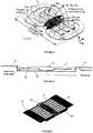
- FIG. 1 shows a layout for a circular power pad.
- the core structure comprises a number of radially directed strips 2 of magnetically permeable material such as ferrite.
- a pad measuring 700 millimetres in diameter (Pd in Figure 1 ) has been built using readily available I93 cores (three per radial strip).
- One or more substantially planar coils 4 are located on top of the core structure.
- shielding comprising a backing plate 6 made of a sheet material, preferably aluminium, which has a peripheral edge in the form of a ring 8 (i.e.
- the aluminium backing 6 and ring 8 add robustness and provide shielding around the pad to leakage fluxes which may exist.
- the ring 8 in prior art circular pads is located immediately adjacent to the edge of the core i.e. the outer end of each radial ferrite strip 2.
- the material from which the backing structure 6 and ring 8 is constructed is preferably one which repels magnetic flux.
- the material is also preferably a good conductor and not lossy.
- the backing 6 may comprise a plate material or a mesh material e.g. aluminium plate or aluminium mesh.
- the backing material may comprise a combination of materials, for example a plate that supports the core, and a mesh section that extends beyond the core perimeter. Advantages associated with use of a mesh material include lower cost, improved integration with the surrounding substrate (in a roadway application for example) and improved transfer of heat from the structure to the surrounding environment.
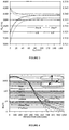
- Magnetic field leakage has been investigated by simulation since simulation results have been shown to match experimental results to within a few percent.
- a transmitter pad is excited with a sinusoidal 23A current at 20kHz and an open circuit receiver pad is placed 125mm above it.
- the magnetic flux density is recorded along a 1m contour extending from the centre of the air gap between the pads outward.
- the flux density is significantly lower above the receiver (being the upper pad) and below the transmitter due to shielding from the aluminium backing plate.
- Fig. 4 where various field leakage curves are plotted.
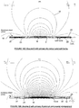
- the flux vectors in Fig. 2(a) show the ring creates a higher reluctance path by causing the field to bend thereby reducing leakage. This 'flux catching' approach results in lower power transfer. Therefore a plate without a ring provides a compromise between leakage and coupling. Flux is easily able to enter the ferrite strips through their ends resulting in increased power.
- Figs 2 , 3 and 4 illustrate pad sensitivity to metallic objects in the vicinity of the pad.
- the chassis of an EV is typically made out of steel and this can severely reduce the quality factor of the receiver or transmitter pads Q L (where Q L is the reactance of the coil divided by its resistance at the frequency of operation). Larger leakage results in more energy lost in the surrounding EV chassis - this loss is proportional to B 2 , thus slight reductions in flux density can be very effective.
- Fig. 4 shows that the ring reduces the area through which flux can escape, but the flux that does escape tends to curve inwards to the opposite pad. Consequently, this flux leakage is less likely to run parallel to the surrounding chassis. Conversely, when the ring is removed as shown in Fig. 2(b) (the back plate is still present), this shaping of the flux path is reduced, and flux is allowed to travel unimpeded toward the chassis, resulting in larger leakage and hence larger loss.
- simply providing a shielding plate with a flange that extends beyond a perimeter of the core may be advantageous.
- providing a lip (such as a ring) so that the flange structure provides a recess or gap between the core and the lip can also be advantageous.
- the International Commission on Non-Ionizing Radiation Protection has produced guidelines that prescribe limits to human exposure to time varying magnetic fields.
- the body average limit is 27 ⁇ T in the range of 3kHz-10MHz (though above 100kHz RF specific levels must be considered). Spot limits can be greater, but their magnitude must be defined by the standards bodies for each country.
- the 700mm circular pads with a ring positioned with a ⁇ Al of 40mm have spot values less than 27 ⁇ T at points greater than 500mm away from the pad centre and therefore the body average will be significantly lower.
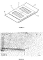
- FIG. 5 Another pad topology which eliminates unwanted rear flux paths by placing two coils above (rather than around) the ferrite strips 2 which form the core, is shown in Figure 5 .
- the ferrite channels the main flux behind the coils (referenced a and b) and forces the flux to establish itself on one side, being the side on which the coils are located. Therefore, any aluminum (not shown in Figure 5 ) provided beneath the core only needs to shield stray fields, resulting in negligible loss.
- the ideal flux paths are shown in Figure 5 arching above the pad. These paths allow good coupling to a similar shaped receiver because the fundamental height (h z ) is essentially proportional to 1 ⁇ 2 of the pad length.
- a key feature to achieving a high coupling factor between two power pads is the intra-pad coupling.
- the height of the intra-pad flux ( ⁇ ip ) is controlled by adjusting the width of the coils a and b in the region where they are immediately adjacent to each other. This region is shaded in Fig. 5 , and referred to as a "flux pipe" between coil a and coil b.
- the fraction of flux ⁇ ip that couples to the receiver pad is mutual flux ( ⁇ M ), therefore the section of coil forming the flux pipe should ideally be made as long as possible.
- the remaining length of the coil should ideally be minimized to save copper and lower R ac . Doing so results in coils shaped like a "D" and since there are two such coils placed back to back, the pad is referred to as a Double D (DD) structure in this document.
- DD Double D
- a backing structure may be used to control the shape of the field in front of the pad and/or to eliminate any fields that happen to propagate around the sides or rear of the pad.
- the effect of such a backing structure or flux shaping structure on the DD pad, and variants of that pad, are discussed below.
- FIG. 13A a design of DD pad for which the backing or shielding plate 16 has an extended flange 16a of 50mm is illustrated.
- Figure 13B shows the further addition of a ring 16b of 5mm thickness.
- Figure 13C A plan view which includes dimensions (in mm) of the simulated structures is shown in Figure 13C .
- the structure of the DD transmitter has 4 rows of 6 ferrite slabs, while the receiver has 4 rows of 8 ferrite slabs.
- the air gap between the transmitter pad and receiver pad is 125mm with no offset.
- the Isc was measured to quantify the power capability (P su ) and the leakage field (B_leakage) was taken at 1m from the centre of the pad in the plane of the pad.
- a coaxial winding 10 was wound about the core 2 so that the return conductors are shielded using a cage 12 formed in the backing /shielding plate 16.
- the plate 16 extends beyond the periphery of the core 2 at the longitudinal ends of the core, forming flanges or end plates 14.
- the design aims to have almost circular flux paths so that maximum flux path height and coupling can be achieved.
- the design is presented in figures 6 and 7 .
- FIG. 8 and 9 This design contains the coaxial winding that goes through the coaxial cage (similar to the Double D Coax of figures 7 and 8 ), as well as Double D windings (similar to the windings a and b of the Double D structure referred to above with reference to Figure 5 ).
- the design shown in Figures 8 and 9 aims to use the Double D windings to further shape the fields and hence increase coupling and reduce leakage fields.
- the design resulting from the optimisation process is shown in Figure 11 .
- the aluminium provides an outer portion with an upwardly directed lip, and a flange peripheral from or dependent from the lip.
- the cage is not required in the Figure 11 construction.
- Figure 12 shows the resulting flux density plot for the design of Figure 11 .
- the backing structure aluminium sheet material
- each coil is wound as a flat spiral but are shown here as a 2 dimensional cross section.
- Each coil comprises 20 turns, so there are 40 wires in the central flux pipe.
- the wires in the flux pipe i.e. between the pole area are all placed with centres 6.6 mm apart, and the end windings 21, 22 in the coils (i.e. those windings at the longitudinal ends of the core) are 20 turns spaced with centres 4 mm apart (essentially touching).
- ferrite 23 has been placed on top of the end windings 21, 22.
- An aluminium separator 16 formed from sheet material has been added to prevent a magnetic short circuit condition.
- the aluminium is located behind core 2 and flanges extend beyond the periphery of the core at the longitudinal ends of the core.
- the flux path is essentially ideal above the ferrite but has some serious undesirable end fluxes below the bottom of the pad.
- With eight ferrite cores in the pad the aluminium 16 transitions between the third and fourth cores, and between the sixth and seventh cores, and covers the ends of the first and eighth cores. In this way the flux pattern of Figure 16B is almost the same as 16A apart from these end fluxes.
- the aluminium plate 16 has been altered so that the flange portions provide a coaxial cage at each end.
- the ferrite 23 is split to be above and below the end windings 21, 22, and the ferrite and end windings are provided within the cage areas.
- the ferrite associated with the end windings has a gap in it. If the gap is not there and the whole space except the winding was filled with ferrite then the inductance of the end windings would be very high but the gap may be varied from a small gap to no ferrite at all to control the effect of the end windings on the flux pattern. As shown in Figure 16D , the unwanted end fluxes are substantially eliminated.
Landscapes
- Engineering & Computer Science (AREA)
- Power Engineering (AREA)
- Transportation (AREA)
- Mechanical Engineering (AREA)
- Computer Networks & Wireless Communication (AREA)
- Physics & Mathematics (AREA)
- Electromagnetism (AREA)
- Regulation Of General Use Transformers (AREA)
- Current-Collector Devices For Electrically Propelled Vehicles (AREA)
- Shielding Devices Or Components To Electric Or Magnetic Fields (AREA)
- Electric Propulsion And Braking For Vehicles (AREA)
Claims (15)
- Magnetflussvorrichtung eines induktiven Leistungsübertragungs(inductive power transfer - IPT)-Systems zum Erzeugen oder Empfangen eines Magnetflusses zum Koppeln mit einer anderen Vorrichtung, um Leistung induktiv zu übertragen, wobei die Magnetflussvorrichtung Folgendes umfasst:ein magnetisch permeables Kernmittel (2);wenigstens eine ebene Spule (4, a, b), die auf einer ersten Seite des Kernmittels bereitgestellt ist und mit dem Kernmittel magnetisch verknüpft ist und;ein Abschirmungsmittel (6, 16) zum Formen des Magnetflusses zum Koppeln und das an einer Seite des Kernmittels gegenüber der ersten Seite bereitgestellt ist, wobei das Abschirmungsmittel einen äußeren Abschnitt umfasst, der einen Umfang, der sich über wenigstens einen Teil eines Umfangs des Kernmittels (2) erstreckt, eine Lippe (8), die sich von dem Umfang des äußeren Abschnitts aus erstreckt, und einen Flansch (14) aufweist, der sich von der Lippe (8) aus erstreckt;wobei sich der äußere Abschnitt von der Vorrichtung aus im Wesentlichen in einer Ebene des Kernmittels (2) erstreckt und die Lippe (8) in einem Winkel relativ zu dem äußeren Abschnitt bereitgestellt ist;wobei der Winkel zwischen im Wesentlichen 90 Grad und 150 Grad relativ zu dem äußeren Abschnitt beträgt.
- Magnetflussvorrichtung des IPT-Systems nach Anspruch 1, wobei das Abschirmungsmittel (6, 16) ein Blechmaterial umfasst.
- Magnetflussvorrichtung des IPT-Systems nach Anspruch 1 oder 2, wobei eine Lücke zwischen dem Kernumfang und der Lippe (8) vorhanden ist, um zu ermöglichen, dass der Magnetfluss zum Koppeln aus dem Kernmittel (2) entweicht.
- Magnetflussvorrichtung des IPT-Systems nach Anspruch 3, wobei die Lücke mit einem nichtmagnetischen Material gefüllt oder teilweise gefüllt ist.
- Magnetflussvorrichtung des IPT-Systems nach einem der vorhergehenden Ansprüche, wobei der äußere Abschnitt im Wesentlichen das Kernmittel (2) abgrenzt.
- Magnetflussvorrichtung des IPT-Systems nach einem der vorhergehenden Ansprüche, wobei der Flansch (14) in einer Ebene liegt, die im Wesentlichen parallel zu einer Ebene ist, innerhalb der der äußere Abschnitt liegt.
- Magnetflussvorrichtung des IPT-Systems nach einem der vorhergehenden Ansprüche, wobei das Abschirmungsmittel (16) ferner ein Gehäuse (12) zum Abschirmen eines Leiters einer weiteren Spule umfasst.
- Magnetflussvorrichtung des IPT-Systems nach einem der Ansprüche 1 bis 6, wobei das Abschirmungsmittel (16) ferner ein Gehäuse (12) zum Abschirmen eines Leiters der Spule umfasst und wobei der Flansch eine Wand des Gehäuses umfasst (12).
- Magnetflussvorrichtung des IPT-Systems nach einem der vorhergehenden Ansprüche, wobei sich der Flansch (14) von der Lippe aus im Wesentlichen angrenzend an die erste Seite des Kernmittels erstreckt.
- Magnetflussvorrichtung des IPT-Systems nach einem der vorhergehenden Ansprüche, wobei die Spule (4, a, b) eine Flachspule umfasst.
- Magnetflussvorrichtung des IPT-Systems nach einem der vorhergehenden Ansprüche, wobei die Spule (4, a, b) in einer ersten Schicht bereitgestellt ist und das Kernmittel (2) in einer zweiten Schicht bereitgestellt ist.
- Magnetflussvorrichtung des IPT-Systems nach einem der vorhergehenden Ansprüche, wobei das Abschirmungsmittel Magnetfluss abweist.
- Magnetflussvorrichtung des IPT-Systems nach einem der vorhergehenden Ansprüche, wobei das Abschirmungsmittel ein Aluminiumblech umfasst.
- Magnetflussvorrichtung des IPT-Systems nach einem der vorhergehenden Ansprüche, wobei die Spule eine kreisförmige Topologie aufweist.
- Magnetflussvorrichtung des IPT-Systems nach einem der vorhergehenden Ansprüche, die ferner eine zweite ebene Spule umfasst, die in einer der folgenden Topologien angeordnet ist:die Spulen sind im Wesentlichen in derselben Ebene angrenzend aneinander angeordnet;die Spulen bilden eine bipolare Topologie aus.
Applications Claiming Priority (2)
| Application Number | Priority Date | Filing Date | Title |
|---|---|---|---|
| NZ59505611 | 2011-09-07 | ||
| PCT/NZ2012/000160 WO2013036146A1 (en) | 2011-09-07 | 2012-09-07 | Magnetic field shaping for inductive power transfer |
Publications (3)
| Publication Number | Publication Date |
|---|---|
| EP2751900A1 EP2751900A1 (de) | 2014-07-09 |
| EP2751900A4 EP2751900A4 (de) | 2015-05-27 |
| EP2751900B1 true EP2751900B1 (de) | 2021-08-04 |
Family
ID=47832425
Family Applications (1)
| Application Number | Title | Priority Date | Filing Date |
|---|---|---|---|
| EP12829832.0A Active EP2751900B1 (de) | 2011-09-07 | 2012-09-07 | Magnetfeldformung für induktive stromübertragung |
Country Status (6)
| Country | Link |
|---|---|
| US (1) | US10263466B2 (de) |
| EP (1) | EP2751900B1 (de) |
| JP (1) | JP6407024B2 (de) |
| KR (1) | KR101970322B1 (de) |
| CN (2) | CN111293788B (de) |
| WO (1) | WO2013036146A1 (de) |
Families Citing this family (34)
| Publication number | Priority date | Publication date | Assignee | Title |
|---|---|---|---|---|
| JP2013501665A (ja) | 2009-08-07 | 2013-01-17 | オークランド ユニサービシズ リミテッド | 道路から電気エネルギーを得る電気車両システム |
| US20150236513A1 (en) * | 2012-02-16 | 2015-08-20 | Auckland Uniservices Limited | Multiple coil flux pad |
| US10573445B2 (en) * | 2013-03-27 | 2020-02-25 | Auckland Uniservices Limited | Electromagnetic field confinement |
| US9676285B2 (en) * | 2013-05-01 | 2017-06-13 | Qualcomm Incorporated | Vehicle charging pad having reduced thickness |
| JP6824737B2 (ja) | 2013-11-13 | 2021-02-03 | アップル インコーポレイテッドApple Inc. | 誘導電力伝送システムのための送信器 |
| US9837204B2 (en) | 2013-12-17 | 2017-12-05 | Qualcomm Incorporated | Coil topologies for inductive power transfer |
| CN103746465A (zh) * | 2014-01-17 | 2014-04-23 | 杭州信多达电器有限公司 | 一种无线充电发射线圈组件 |
| JP2015142019A (ja) * | 2014-01-29 | 2015-08-03 | トヨタ自動車株式会社 | 受電装置 |
| WO2015178781A1 (en) | 2014-05-19 | 2015-11-26 | Powerbyproxi Limited | Magnetically permeable core and an inductive power transfer coil arrangement |
| US10269486B2 (en) | 2014-05-19 | 2019-04-23 | Apple Inc. | Magnetically permeable core and inductive power transfer coil arrangement |
| JP6519773B2 (ja) * | 2014-05-22 | 2019-05-29 | 株式会社デンソー | 電力伝送用パッドおよび非接触電力伝送システム |
| US9812875B2 (en) | 2014-09-05 | 2017-11-07 | Qualcomm Incorporated | Systems and methods for adjusting magnetic field distribution using ferromagnetic material |
| US11031826B2 (en) * | 2014-09-11 | 2021-06-08 | Auckland Uniservices Limited | Magnetic flux coupling structures with controlled flux cancellation |
| US9941708B2 (en) | 2014-11-05 | 2018-04-10 | Qualcomm Incorporated | Systems, methods, and apparatus for integrated tuning capacitors in charging coil structure |
| US9960607B2 (en) | 2014-12-29 | 2018-05-01 | Qualcomm Incorporated | Systems, methods and apparatus for reducing intra-base array network coupling |
| GB2535463A (en) | 2015-02-16 | 2016-08-24 | Bombardier Transp Gmbh | Power transfer unit of a system for inductive power transfer, a method of manufacturing a power transfer unit and of operating a power transfer unit |
| US9929606B2 (en) * | 2015-05-11 | 2018-03-27 | Qualcomm Incorporated | Integration of positioning antennas in wireless inductive charging power applications |
| US10510482B2 (en) | 2015-06-26 | 2019-12-17 | Bombardier Primove Gmbh | Primary sided-arrangement of primary winding structures, a method of manufacturing the primary-sided arrangement, a system for inductive power transfer and a method for inductively supplying power to a vehicle |
| WO2017204663A1 (en) | 2016-05-25 | 2017-11-30 | Powerbyproxi Limited | A coil arrangement |
| WO2017209630A1 (en) | 2016-06-01 | 2017-12-07 | Powerbyproxi Limited | A powered joint with wireless transfer |
| US20180131242A1 (en) | 2016-11-04 | 2018-05-10 | Powerbyproxi Limited | Inductive power transmitter, receiver and method of operation |
| CN206834025U (zh) | 2016-11-18 | 2018-01-02 | 鲍尔拜普罗克西有限公司 | 感应式电力传输线圈组件 |
| US10978911B2 (en) | 2016-12-19 | 2021-04-13 | Apple Inc. | Inductive power transfer system |
| US20180233961A1 (en) | 2017-02-14 | 2018-08-16 | Aiguo Hu | Inductive power transfer |
| US11458327B2 (en) | 2017-07-24 | 2022-10-04 | Regenesis Biomedical, Inc. | High-power pulsed electromagnetic field applicator system |
| WO2019108071A1 (en) * | 2017-12-01 | 2019-06-06 | Auckland Uniservices Limited | A misalignment tolerant hybrid wireless power transfer system |
| US11207541B2 (en) | 2018-03-23 | 2021-12-28 | Regenesis Biomedical, Inc. | High-power pulsed electromagnetic field applicator systems |
| US10593468B2 (en) | 2018-04-05 | 2020-03-17 | Apple Inc. | Inductive power transfer assembly |
| US11547848B2 (en) | 2018-06-21 | 2023-01-10 | Regenesis Biomedical, Inc. | High-power pulsed electromagnetic field applicator systems |
| US11833363B2 (en) | 2019-10-25 | 2023-12-05 | Regenesis Biomedical, Inc. | Current-based RF driver for pulsed electromagnetic field applicator systems |
| CN111463000B (zh) * | 2020-05-20 | 2021-08-24 | 河北工业大学 | 一种适用于电动汽车无线供电系统的复合式屏蔽结构 |
| WO2022175714A1 (en) * | 2021-02-17 | 2022-08-25 | Daymak Inc. | Wireless power transfer (wpt) charging system for an electric vehicle |
| US20240278031A1 (en) * | 2021-06-09 | 2024-08-22 | Regenesis Biomedical, Inc. | Method and apparatus for providing pulsed electromagnetic field therapy |
| EP4433323A4 (de) * | 2021-11-19 | 2025-11-26 | Auckland Uniservices Ltd | Vorrichtung zur drahtlosen stromübertragung |
Family Cites Families (22)
| Publication number | Priority date | Publication date | Assignee | Title |
|---|---|---|---|---|
| US5000178A (en) * | 1986-05-23 | 1991-03-19 | Lti Biomedical, Inc. | Shielded electromagnetic transducer |
| GB9025391D0 (en) | 1990-11-22 | 1991-01-09 | Rue Company The Plc De | Magnetic field sensor and method |
| JP2673876B2 (ja) * | 1994-12-05 | 1997-11-05 | ティーディーケイ株式会社 | 電磁誘導コイルの駆動回路及び該駆動回路を用いた充電装置 |
| DE19746919A1 (de) * | 1997-10-24 | 1999-05-06 | Daimler Chrysler Ag | Elektrische Übertragungsvorrichtung |
| GB0210886D0 (en) * | 2002-05-13 | 2002-06-19 | Zap Wireless Technologies Ltd | Improvements relating to contact-less power transfer |
| GB2388716B (en) * | 2002-05-13 | 2004-10-20 | Splashpower Ltd | Improvements relating to contact-less power transfer |
| US8350655B2 (en) * | 2003-02-26 | 2013-01-08 | Analogic Corporation | Shielded power coupling device |
| GB0320960D0 (en) * | 2003-09-08 | 2003-10-08 | Splashpower Ltd | Improvements relating to improving flux patterns of inductive charging pads |
| WO2008140333A2 (en) | 2007-05-10 | 2008-11-20 | Auckland Uniservices Limited | Multi power sourced electric vehicle |
| KR20100017582A (ko) * | 2007-05-10 | 2010-02-16 | 오클랜드 유니서비시즈 리미티드 | 멀티 전력을 공급받는 전기 자동차 |
| JP4453741B2 (ja) * | 2007-10-25 | 2010-04-21 | トヨタ自動車株式会社 | 電動車両および車両用給電装置 |
| JP4743244B2 (ja) * | 2008-09-18 | 2011-08-10 | トヨタ自動車株式会社 | 非接触受電装置 |
| US8401469B2 (en) * | 2008-09-26 | 2013-03-19 | Hewlett-Packard Development Company, L.P. | Shield for use with a computing device that receives an inductive signal transmission |
| JP2010098807A (ja) * | 2008-10-15 | 2010-04-30 | Toyota Motor Corp | 非接触給電システム |
| JP5274989B2 (ja) * | 2008-11-12 | 2013-08-28 | 昭和飛行機工業株式会社 | 非接触給電装置 |
| EP2394345B1 (de) * | 2009-02-05 | 2019-08-07 | Auckland UniServices Limited | Induktive leistungsübertragungsvorrichtung |
| CA2751595C (en) * | 2009-02-05 | 2023-08-01 | Auckland Uniservices Limited | Inductive power transfer apparatus |
| KR100944113B1 (ko) | 2009-02-27 | 2010-02-24 | 한국과학기술원 | 전기자동차용 전원공급 시스템 및 방법 |
| JP2011010435A (ja) * | 2009-06-25 | 2011-01-13 | Fujitsu Ten Ltd | 非接触式電力供給装置および非接触式電力供給ユニット |
| JP2013501665A (ja) | 2009-08-07 | 2013-01-17 | オークランド ユニサービシズ リミテッド | 道路から電気エネルギーを得る電気車両システム |
| JP5746049B2 (ja) * | 2009-12-17 | 2015-07-08 | トヨタ自動車株式会社 | 受電装置および送電装置 |
| CN201947065U (zh) * | 2010-10-18 | 2011-08-24 | 陈庭勋 | 贴近式无线输电装置结构 |
-
2012
- 2012-09-07 CN CN202010114042.3A patent/CN111293788B/zh active Active
- 2012-09-07 EP EP12829832.0A patent/EP2751900B1/de active Active
- 2012-09-07 JP JP2014529639A patent/JP6407024B2/ja active Active
- 2012-09-07 WO PCT/NZ2012/000160 patent/WO2013036146A1/en not_active Ceased
- 2012-09-07 CN CN201280052907.1A patent/CN103947072A/zh active Pending
- 2012-09-07 US US14/240,191 patent/US10263466B2/en active Active
- 2012-09-07 KR KR1020147007332A patent/KR101970322B1/ko active Active
Non-Patent Citations (1)
| Title |
|---|
| None * |
Also Published As
| Publication number | Publication date |
|---|---|
| KR20140065421A (ko) | 2014-05-29 |
| JP2014532296A (ja) | 2014-12-04 |
| US10263466B2 (en) | 2019-04-16 |
| CN111293788A (zh) | 2020-06-16 |
| EP2751900A4 (de) | 2015-05-27 |
| WO2013036146A1 (en) | 2013-03-14 |
| US20140361630A1 (en) | 2014-12-11 |
| CN103947072A (zh) | 2014-07-23 |
| JP6407024B2 (ja) | 2018-10-17 |
| KR101970322B1 (ko) | 2019-04-18 |
| CN111293788B (zh) | 2023-11-03 |
| EP2751900A1 (de) | 2014-07-09 |
Similar Documents
| Publication | Publication Date | Title |
|---|---|---|
| EP2751900B1 (de) | Magnetfeldformung für induktive stromübertragung | |
| Mohammad et al. | Core design and optimization for better misalignment tolerance and higher range of wireless charging of PHEV | |
| EP2870675B1 (de) | Magnetischer Flusskoppler | |
| KR102167688B1 (ko) | 이동수단의 무선충전용 수신코일 및 이를 이용한 이동수단의 무선충전용 전력수신장치 | |
| JP5531500B2 (ja) | 無線電力伝送システムにおける電磁波遮蔽装置および無線電力送電装置 | |
| US10340078B2 (en) | Coil topologies for inductive power transfer | |
| US10014104B2 (en) | Coil arrangements in wireless power transfer systems for low electromagnetic emissions | |
| EP2576274B1 (de) | Drahtlose leistungsempfangseinheit, drahtlose leistungsübertragungseinheit, drahtlose leistungsübertragungsvorrichtung und verwendung von einer leistungsübertragungsvorrichtung | |
| KR101780758B1 (ko) | 유도 전력 전송 장치 | |
| US6407470B1 (en) | Electric power transmission device | |
| JP5437650B2 (ja) | 非接触給電装置 | |
| EP2841293B1 (de) | Bereitstellung eines landfahrzeuges, insbesondere eines schienenfahrzeuges oder strassenfahrzeuges, mit elektrischer energie durch induktion | |
| EP2698799B1 (de) | Magnetische Konfiguration für hocheffiziente Stromverarbeitung | |
| Etta et al. | Design of low-loss magnetic-core toroidal inductor for multi-MHz wireless power transfer systems | |
| US11756727B2 (en) | Wireless power transfer coupling structures with reduced leakage flux | |
| EP3262665B1 (de) | Leistungsübertragungseinheit eines systems für induktive leistungsübertragung, verfahren zur herstellung einer primären leistungsübertragungseinheit und zum betrieb einer primären leistungsübertragungseinheit | |
| Bui et al. | A 6.78-MHz Free-Positioning Wireless Charging Bowl with Optimized Passive Electromagnetic Shield for Wearable Devices | |
| Zhu et al. | Optimization of “I” Type Shielding for Low Air-Gap Magnetic and Electric Fields Inductive Wireless Power Transfer | |
| Benalia et al. | A Comparative Study and Parameters Analysis of Coils in Inductive Charging For Electric Vehicles | |
| KR20150102299A (ko) | Ipt를 이용한 무선 전력전달 시스템에 있어서 emf 상쇄장치 | |
| HK1208069B (en) | Providing a land vehicle, in particular a rail vehicle or a road automobile, with electric energy by induction |
Legal Events
| Date | Code | Title | Description |
|---|---|---|---|
| PUAI | Public reference made under article 153(3) epc to a published international application that has entered the european phase |
Free format text: ORIGINAL CODE: 0009012 |
|
| 17P | Request for examination filed |
Effective date: 20140319 |
|
| AK | Designated contracting states |
Kind code of ref document: A1 Designated state(s): AL AT BE BG CH CY CZ DE DK EE ES FI FR GB GR HR HU IE IS IT LI LT LU LV MC MK MT NL NO PL PT RO RS SE SI SK SM TR |
|
| DAX | Request for extension of the european patent (deleted) | ||
| RA4 | Supplementary search report drawn up and despatched (corrected) |
Effective date: 20150429 |
|
| RIC1 | Information provided on ipc code assigned before grant |
Ipc: H01F 38/14 20060101ALI20150422BHEP Ipc: H01F 27/36 20060101ALI20150422BHEP Ipc: H02J 7/00 20060101AFI20150422BHEP |
|
| STAA | Information on the status of an ep patent application or granted ep patent |
Free format text: STATUS: REQUEST FOR EXAMINATION WAS MADE |
|
| R17P | Request for examination filed (corrected) |
Effective date: 20140319 |
|
| RAP1 | Party data changed (applicant data changed or rights of an application transferred) |
Owner name: AUCKLAND UNISERVICES LIMITED |
|
| 111L | Licence recorded |
Designated state(s): AL AT BE BG CH CY CZ DE DK EE ES FI FR GB GR HR HU IE IS IT LT LU LV MC MK MT NL NO PL PT RO RS SE SI SK SM TR Free format text: EXCLUSIVE LICENSE Name of requester: HALO INDUCTIVE POWER TECHNOLOGIES LIMITED, GB Effective date: 20180622 |
|
| R11L | Licence recorded (corrected) |
Designated state(s): AL AT BE BG CH CY CZ DE DK EE ES FI FR GB GR HR HU IE IS IT LT LU LV MC MK MT NL NO PL PT RO RS SE SI SK SM TR Free format text: EXCLUSIVE LICENSE Name of requester: QUALCOMM INCORPORATED, US Effective date: 20180622 |
|
| RAP1 | Party data changed (applicant data changed or rights of an application transferred) |
Owner name: AUCKLAND UNISERVICES LIMITED |
|
| STAA | Information on the status of an ep patent application or granted ep patent |
Free format text: STATUS: EXAMINATION IS IN PROGRESS |
|
| 17Q | First examination report despatched |
Effective date: 20200318 |
|
| REG | Reference to a national code |
Ref country code: DE Ref legal event code: R079 Ref document number: 602012076314 Country of ref document: DE Free format text: PREVIOUS MAIN CLASS: H02J0007000000 Ipc: H01F0038140000 |
|
| GRAP | Despatch of communication of intention to grant a patent |
Free format text: ORIGINAL CODE: EPIDOSNIGR1 |
|
| STAA | Information on the status of an ep patent application or granted ep patent |
Free format text: STATUS: GRANT OF PATENT IS INTENDED |
|
| RIC1 | Information provided on ipc code assigned before grant |
Ipc: H01F 38/14 20060101AFI20210316BHEP Ipc: H01F 27/36 20060101ALI20210316BHEP Ipc: B60L 53/12 20190101ALI20210316BHEP Ipc: B60L 53/30 20190101ALI20210316BHEP Ipc: B60L 53/39 20190101ALI20210316BHEP Ipc: H02J 7/00 20060101ALI20210316BHEP |
|
| INTG | Intention to grant announced |
Effective date: 20210412 |
|
| RIN1 | Information on inventor provided before grant (corrected) |
Inventor name: BOYS, JOHN TALBOT Inventor name: COVIC, GRANT ANTHONY |
|
| GRAS | Grant fee paid |
Free format text: ORIGINAL CODE: EPIDOSNIGR3 |
|
| GRAA | (expected) grant |
Free format text: ORIGINAL CODE: 0009210 |
|
| STAA | Information on the status of an ep patent application or granted ep patent |
Free format text: STATUS: THE PATENT HAS BEEN GRANTED |
|
| 111L | Licence recorded |
Designated state(s): AL AT BE BG CH CY CZ DE DK EE ES FI FR GB GR HR HU IE IS IT LT LU LV MC MK MT NL NO PL PT RO RS SE SI SK SM TR Free format text: EXCLUSIVE LICENSE Name of requester: QUALCOMM INCORPORATED, US Effective date: 20180622 |
|
| AK | Designated contracting states |
Kind code of ref document: B1 Designated state(s): AL AT BE BG CH CY CZ DE DK EE ES FI FR GB GR HR HU IE IS IT LI LT LU LV MC MK MT NL NO PL PT RO RS SE SI SK SM TR |
|
| REG | Reference to a national code |
Ref country code: GB Ref legal event code: FG4D |
|
| REG | Reference to a national code |
Ref country code: AT Ref legal event code: REF Ref document number: 1417837 Country of ref document: AT Kind code of ref document: T Effective date: 20210815 |
|
| REG | Reference to a national code |
Ref country code: CH Ref legal event code: EP |
|
| REG | Reference to a national code |
Ref country code: DE Ref legal event code: R096 Ref document number: 602012076314 Country of ref document: DE |
|
| REG | Reference to a national code |
Ref country code: IE Ref legal event code: FG4D |
|
| REG | Reference to a national code |
Ref country code: LT Ref legal event code: MG9D |
|
| REG | Reference to a national code |
Ref country code: NL Ref legal event code: MP Effective date: 20210804 |
|
| REG | Reference to a national code |
Ref country code: AT Ref legal event code: MK05 Ref document number: 1417837 Country of ref document: AT Kind code of ref document: T Effective date: 20210804 |
|
| PG25 | Lapsed in a contracting state [announced via postgrant information from national office to epo] |
Ref country code: SE Free format text: LAPSE BECAUSE OF FAILURE TO SUBMIT A TRANSLATION OF THE DESCRIPTION OR TO PAY THE FEE WITHIN THE PRESCRIBED TIME-LIMIT Effective date: 20210804 Ref country code: HR Free format text: LAPSE BECAUSE OF FAILURE TO SUBMIT A TRANSLATION OF THE DESCRIPTION OR TO PAY THE FEE WITHIN THE PRESCRIBED TIME-LIMIT Effective date: 20210804 Ref country code: NO Free format text: LAPSE BECAUSE OF FAILURE TO SUBMIT A TRANSLATION OF THE DESCRIPTION OR TO PAY THE FEE WITHIN THE PRESCRIBED TIME-LIMIT Effective date: 20211104 Ref country code: PT Free format text: LAPSE BECAUSE OF FAILURE TO SUBMIT A TRANSLATION OF THE DESCRIPTION OR TO PAY THE FEE WITHIN THE PRESCRIBED TIME-LIMIT Effective date: 20211206 Ref country code: RS Free format text: LAPSE BECAUSE OF FAILURE TO SUBMIT A TRANSLATION OF THE DESCRIPTION OR TO PAY THE FEE WITHIN THE PRESCRIBED TIME-LIMIT Effective date: 20210804 Ref country code: FI Free format text: LAPSE BECAUSE OF FAILURE TO SUBMIT A TRANSLATION OF THE DESCRIPTION OR TO PAY THE FEE WITHIN THE PRESCRIBED TIME-LIMIT Effective date: 20210804 Ref country code: ES Free format text: LAPSE BECAUSE OF FAILURE TO SUBMIT A TRANSLATION OF THE DESCRIPTION OR TO PAY THE FEE WITHIN THE PRESCRIBED TIME-LIMIT Effective date: 20210804 Ref country code: LT Free format text: LAPSE BECAUSE OF FAILURE TO SUBMIT A TRANSLATION OF THE DESCRIPTION OR TO PAY THE FEE WITHIN THE PRESCRIBED TIME-LIMIT Effective date: 20210804 Ref country code: AT Free format text: LAPSE BECAUSE OF FAILURE TO SUBMIT A TRANSLATION OF THE DESCRIPTION OR TO PAY THE FEE WITHIN THE PRESCRIBED TIME-LIMIT Effective date: 20210804 Ref country code: BG Free format text: LAPSE BECAUSE OF FAILURE TO SUBMIT A TRANSLATION OF THE DESCRIPTION OR TO PAY THE FEE WITHIN THE PRESCRIBED TIME-LIMIT Effective date: 20211104 |
|
| PG25 | Lapsed in a contracting state [announced via postgrant information from national office to epo] |
Ref country code: PL Free format text: LAPSE BECAUSE OF FAILURE TO SUBMIT A TRANSLATION OF THE DESCRIPTION OR TO PAY THE FEE WITHIN THE PRESCRIBED TIME-LIMIT Effective date: 20210804 Ref country code: LV Free format text: LAPSE BECAUSE OF FAILURE TO SUBMIT A TRANSLATION OF THE DESCRIPTION OR TO PAY THE FEE WITHIN THE PRESCRIBED TIME-LIMIT Effective date: 20210804 Ref country code: GR Free format text: LAPSE BECAUSE OF FAILURE TO SUBMIT A TRANSLATION OF THE DESCRIPTION OR TO PAY THE FEE WITHIN THE PRESCRIBED TIME-LIMIT Effective date: 20211105 |
|
| PG25 | Lapsed in a contracting state [announced via postgrant information from national office to epo] |
Ref country code: NL Free format text: LAPSE BECAUSE OF FAILURE TO SUBMIT A TRANSLATION OF THE DESCRIPTION OR TO PAY THE FEE WITHIN THE PRESCRIBED TIME-LIMIT Effective date: 20210804 |
|
| PG25 | Lapsed in a contracting state [announced via postgrant information from national office to epo] |
Ref country code: DK Free format text: LAPSE BECAUSE OF FAILURE TO SUBMIT A TRANSLATION OF THE DESCRIPTION OR TO PAY THE FEE WITHIN THE PRESCRIBED TIME-LIMIT Effective date: 20210804 |
|
| REG | Reference to a national code |
Ref country code: CH Ref legal event code: PL |
|
| REG | Reference to a national code |
Ref country code: DE Ref legal event code: R097 Ref document number: 602012076314 Country of ref document: DE |
|
| REG | Reference to a national code |
Ref country code: BE Ref legal event code: MM Effective date: 20210930 |
|
| PG25 | Lapsed in a contracting state [announced via postgrant information from national office to epo] |
Ref country code: SM Free format text: LAPSE BECAUSE OF FAILURE TO SUBMIT A TRANSLATION OF THE DESCRIPTION OR TO PAY THE FEE WITHIN THE PRESCRIBED TIME-LIMIT Effective date: 20210804 Ref country code: SK Free format text: LAPSE BECAUSE OF FAILURE TO SUBMIT A TRANSLATION OF THE DESCRIPTION OR TO PAY THE FEE WITHIN THE PRESCRIBED TIME-LIMIT Effective date: 20210804 Ref country code: RO Free format text: LAPSE BECAUSE OF FAILURE TO SUBMIT A TRANSLATION OF THE DESCRIPTION OR TO PAY THE FEE WITHIN THE PRESCRIBED TIME-LIMIT Effective date: 20210804 Ref country code: MC Free format text: LAPSE BECAUSE OF FAILURE TO SUBMIT A TRANSLATION OF THE DESCRIPTION OR TO PAY THE FEE WITHIN THE PRESCRIBED TIME-LIMIT Effective date: 20210804 Ref country code: EE Free format text: LAPSE BECAUSE OF FAILURE TO SUBMIT A TRANSLATION OF THE DESCRIPTION OR TO PAY THE FEE WITHIN THE PRESCRIBED TIME-LIMIT Effective date: 20210804 Ref country code: CZ Free format text: LAPSE BECAUSE OF FAILURE TO SUBMIT A TRANSLATION OF THE DESCRIPTION OR TO PAY THE FEE WITHIN THE PRESCRIBED TIME-LIMIT Effective date: 20210804 Ref country code: AL Free format text: LAPSE BECAUSE OF FAILURE TO SUBMIT A TRANSLATION OF THE DESCRIPTION OR TO PAY THE FEE WITHIN THE PRESCRIBED TIME-LIMIT Effective date: 20210804 |
|
| PLBE | No opposition filed within time limit |
Free format text: ORIGINAL CODE: 0009261 |
|
| STAA | Information on the status of an ep patent application or granted ep patent |
Free format text: STATUS: NO OPPOSITION FILED WITHIN TIME LIMIT |
|
| 26N | No opposition filed |
Effective date: 20220506 |
|
| PG25 | Lapsed in a contracting state [announced via postgrant information from national office to epo] |
Ref country code: LU Free format text: LAPSE BECAUSE OF NON-PAYMENT OF DUE FEES Effective date: 20210907 Ref country code: IT Free format text: LAPSE BECAUSE OF FAILURE TO SUBMIT A TRANSLATION OF THE DESCRIPTION OR TO PAY THE FEE WITHIN THE PRESCRIBED TIME-LIMIT Effective date: 20210804 Ref country code: IE Free format text: LAPSE BECAUSE OF NON-PAYMENT OF DUE FEES Effective date: 20210907 Ref country code: BE Free format text: LAPSE BECAUSE OF NON-PAYMENT OF DUE FEES Effective date: 20210930 |
|
| PG25 | Lapsed in a contracting state [announced via postgrant information from national office to epo] |
Ref country code: SI Free format text: LAPSE BECAUSE OF FAILURE TO SUBMIT A TRANSLATION OF THE DESCRIPTION OR TO PAY THE FEE WITHIN THE PRESCRIBED TIME-LIMIT Effective date: 20210804 Ref country code: LI Free format text: LAPSE BECAUSE OF NON-PAYMENT OF DUE FEES Effective date: 20210930 Ref country code: CH Free format text: LAPSE BECAUSE OF NON-PAYMENT OF DUE FEES Effective date: 20210930 |
|
| PG25 | Lapsed in a contracting state [announced via postgrant information from national office to epo] |
Ref country code: FR Free format text: LAPSE BECAUSE OF NON-PAYMENT OF DUE FEES Effective date: 20211004 |
|
| PG25 | Lapsed in a contracting state [announced via postgrant information from national office to epo] |
Ref country code: HU Free format text: LAPSE BECAUSE OF FAILURE TO SUBMIT A TRANSLATION OF THE DESCRIPTION OR TO PAY THE FEE WITHIN THE PRESCRIBED TIME-LIMIT; INVALID AB INITIO Effective date: 20120907 Ref country code: CY Free format text: LAPSE BECAUSE OF FAILURE TO SUBMIT A TRANSLATION OF THE DESCRIPTION OR TO PAY THE FEE WITHIN THE PRESCRIBED TIME-LIMIT Effective date: 20210804 |
|
| P01 | Opt-out of the competence of the unified patent court (upc) registered |
Effective date: 20230516 |
|
| PG25 | Lapsed in a contracting state [announced via postgrant information from national office to epo] |
Ref country code: MK Free format text: LAPSE BECAUSE OF FAILURE TO SUBMIT A TRANSLATION OF THE DESCRIPTION OR TO PAY THE FEE WITHIN THE PRESCRIBED TIME-LIMIT Effective date: 20210804 |
|
| PG25 | Lapsed in a contracting state [announced via postgrant information from national office to epo] |
Ref country code: TR Free format text: LAPSE BECAUSE OF FAILURE TO SUBMIT A TRANSLATION OF THE DESCRIPTION OR TO PAY THE FEE WITHIN THE PRESCRIBED TIME-LIMIT Effective date: 20210804 |
|
| PG25 | Lapsed in a contracting state [announced via postgrant information from national office to epo] |
Ref country code: MT Free format text: LAPSE BECAUSE OF FAILURE TO SUBMIT A TRANSLATION OF THE DESCRIPTION OR TO PAY THE FEE WITHIN THE PRESCRIBED TIME-LIMIT Effective date: 20210804 |
|
| PGFP | Annual fee paid to national office [announced via postgrant information from national office to epo] |
Ref country code: GB Payment date: 20260326 Year of fee payment: 14 |
|
| PGFP | Annual fee paid to national office [announced via postgrant information from national office to epo] |
Ref country code: DE Payment date: 20260326 Year of fee payment: 14 |