EP2752657A2 - Système et procédés pour inspection à distance de structures d'avion - Google Patents
Système et procédés pour inspection à distance de structures d'avion Download PDFInfo
- Publication number
- EP2752657A2 EP2752657A2 EP13199830.4A EP13199830A EP2752657A2 EP 2752657 A2 EP2752657 A2 EP 2752657A2 EP 13199830 A EP13199830 A EP 13199830A EP 2752657 A2 EP2752657 A2 EP 2752657A2
- Authority
- EP
- European Patent Office
- Prior art keywords
- anomaly
- target object
- area
- image
- recited
- Prior art date
- Legal status (The legal status is an assumption and is not a legal conclusion. Google has not performed a legal analysis and makes no representation as to the accuracy of the status listed.)
- Granted
Links
Images


Classifications
-
- G—PHYSICS
- G01—MEASURING; TESTING
- G01M—TESTING STATIC OR DYNAMIC BALANCE OF MACHINES OR STRUCTURES; TESTING OF STRUCTURES OR APPARATUS, NOT OTHERWISE PROVIDED FOR
- G01M99/00—Subject matter not provided for in other groups of this subclass
-
- G—PHYSICS
- G01—MEASURING; TESTING
- G01N—INVESTIGATING OR ANALYSING MATERIALS BY DETERMINING THEIR CHEMICAL OR PHYSICAL PROPERTIES
- G01N21/00—Investigating or analysing materials by the use of optical means, i.e. using sub-millimetre waves, infrared, visible or ultraviolet light
- G01N21/84—Systems specially adapted for particular applications
- G01N21/8422—Investigating thin films, e.g. matrix isolation method
-
- G—PHYSICS
- G01—MEASURING; TESTING
- G01N—INVESTIGATING OR ANALYSING MATERIALS BY DETERMINING THEIR CHEMICAL OR PHYSICAL PROPERTIES
- G01N21/00—Investigating or analysing materials by the use of optical means, i.e. using sub-millimetre waves, infrared, visible or ultraviolet light
- G01N21/84—Systems specially adapted for particular applications
- G01N21/88—Investigating the presence of flaws or contamination
- G01N21/8851—Scan or image signal processing specially adapted therefor, e.g. for scan signal adjustment, for detecting different kinds of defects, for compensating for structures, markings, edges
-
- G—PHYSICS
- G01—MEASURING; TESTING
- G01N—INVESTIGATING OR ANALYSING MATERIALS BY DETERMINING THEIR CHEMICAL OR PHYSICAL PROPERTIES
- G01N21/00—Investigating or analysing materials by the use of optical means, i.e. using sub-millimetre waves, infrared, visible or ultraviolet light
- G01N21/84—Systems specially adapted for particular applications
- G01N21/88—Investigating the presence of flaws or contamination
- G01N21/8851—Scan or image signal processing specially adapted therefor, e.g. for scan signal adjustment, for detecting different kinds of defects, for compensating for structures, markings, edges
- G01N2021/8854—Grading and classifying of flaws
- G01N2021/8867—Grading and classifying of flaws using sequentially two or more inspection runs, e.g. coarse and fine, or detecting then analysing
Definitions
- This disclosure generally relates to automated systems and methods for stand-off inspection of structures, such as aircraft components.
- this disclosure relates to automated methods and systems for locating visible differences on a structural component from a distance and accurately measuring the locations of potential damage relative to a coordinate system of the inspected structure.
- An efficient and automated process for addressing this problem would be valuable to many organizations involved in building and maintaining large vehicles and structures.
- a dielectric top is a barrier dielectric patch which covers the head of a fastener to prevent lightning strikes from penetrating the structure and entering the fuel tank area. It is known that dielectric tops are susceptible to cracking after a certain number of years in service. An operator of aircraft so equipped tries to identify cracked dielectric tops in an accurate and fast manner, and then measure the depth of those cracks in an accurate and fast manner. Cracks above a certain length may require repair or replacement of the dielectric tops.
- the existing solution for dielectric top inspection is a completely manual visual inspection and repair. Cracks greater than 0.1" in length are not allowed. Inspecting for these cracks will impact the service readiness of the airplane. Moreover, a typical airplane has about 18,000 dielectric tops.
- NDE nondestructive evaluation
- the subject matter disclosed herein is directed to systems and methods which combine stand-off local positioning and stand-off NDE. More specifically, the systems described hereinafter provide for simultaneous and autonomous stand-off inspection locating, stand-off NDE, NDE measurement data mapping/correlation to a three-dimensional structure, and data storage and retrieval capability.
- the system combines the capabilities of a local positioning system with any one of a group of NDE hardware that can be used at a distance from the structure under inspection.
- the particular systems disclosed hereinafter provide a very rapid discrimination of cracked and non-cracked dielectric tops using a local positioning system to locate all specified dielectric tops and indicate those tops that call for further inspection; in addition it provides automated NDE options for measuring the depth of the cracks in those dielectric tops.
- the results of the crack measurements are saved in a remote database and autonomous repairs of various levels are initiated based upon the results. Repair or removal of cracked tops is done separately.
- the means and methods disclosed hereinafter for implementing the combination of local positioning with stand-off NDE is not limited in its application to detecting cracks in dielectric tops.
- Other aircraft components can also be inspected using the techniques disclosed herein. More generally, the disclosed techniques have application in any situation where stand-off inspection of a structure is called for.
- Some anomalies might be single points, in which case the system will record the position coordinates of the anomaly.
- additional location data can be recorded.
- the system records sets of position coordinates corresponding to the set of two or more points. But when the anomaly becomes an area, then a more complex definition of the region is used. In this case, both position data and orientation data are recorded to define where it is located.
- One aspect of the subject matter disclosed hereinafter is a system comprising local positioning system hardware, a NDE instrument, and a computer system programmed to execute the following operations: (a) controlling the local positioning system hardware to determine a direction vector to the target object and acquire image data representing an image of an area on a surface of the target object which is intersected by the direction vector; (b) processing the image data to determine whether the image of the area includes information indicating the presence of an anomaly in the area; (c) if it is determined in operation (b) that the image data includes information indicating the presence of an anomaly in the area, determining coordinates of a position of the anomaly relative to the coordinate system of the target object; (d) directing the NDE instrument toward an area on the target object having the recorded coordinates; and (e) controlling the NDE instrument to acquire NDE measurement data representing a characteristic of the anomaly using a stand-off NDE technique.
- the computer system may be further programmed to process the NDE measurement data to determine a value for the anomaly characteristic.
- the local positioning system hardware comprises a video camera, a laser range meter, and a motion controlled pan-tilt unit that provides position measurement data for use in estimating the location of the video camera relative to the target object.
- Another aspect is a system for stand-off inspection comprising a video camera, a laser range meter and a NDE instrument, all supported by a motion-controlled pan-tilt mechanism.
- the system further comprises a computer system is programmed to perform the following operations: controlling said video camera, said laser range meter and said motion-controlled pan-tilt mechanism to determine a direction vector to the target object, and acquire image data representing an image of an area on a surface of the target object which is intersected by the direction vector; processing the image to determine whether an anomaly is present in the area; if an anomaly is present, determining coordinates of a position of the anomaly in a coordinate system of the target object; and directing the NDE instrument toward an area on the target object corresponding to the coordinates.
- the computer system is further programmed to measure a characteristic of the anomaly (e.g., the depth of a crack).
- Yet another aspect is a method for NDE inspection of an area on a surface of a target object, comprising: determining, relative to a coordinate system associated with a target object, coordinates of a position for a visibly detectable anomaly (i.e. difference from nominal) on a surface of a target object using a local positioning system; directing a NDE instrument toward the visibly detectable anomaly using the recorded coordinates; acquiring measurement data representing a characteristic of the visibly detectable anomaly using the NDE instrument; and processing the measurement data to determine a value for the characteristic of the visibly detectable anomaly.
- a method for detecting and determining a position of a visible anomaly on a target object comprising: (a) locating, by position and orientation, a local positioning system with respect to a target object; (b) determining an offset between the position and orientation of the local positioning system and a prior position and orientation of a local positioning system previously utilized to collect a set of reference images of the target object, the prior position and orientation being in the coordinate system of the target object; (c) relocating, by position and orientation, the local positioning system with respect to the target object in accordance with the offset determined in step (b); (d) acquiring a set of images of the target object from the position and orientation of the relocated local positioning system; (e) comparing the set of images to corresponding images within the set of reference images to detect a difference between the acquired images and the corresponding reference images; (f) determining coordinates of a position of the detected difference in the coordinate system of the target object; (g) recording the coordinates of the position
- a method for stand-off inspection comprises: (a) acquiring position measurement data of an area on a surface of a target object relative to the coordinate system of the target object using a local positioning system; (b) acquiring image data representing the area; (c) processing the image data to determine whether the image data includes information indicating the presence of an anomaly in the area; (d) if it is determined in step (c) that the image data includes information indicating the presence of an anomaly in the area, determining coordinates of a position of the anomaly relative to the coordinate system of the target object; (e) recording the coordinates of the position of the anomaly; (e) directing a NDE instrument toward an area on the target object having the recorded coordinates; and (f) acquiring NDE measurement data representing a first characteristic of the anomaly using a stand-off NDE technique.
- the method may further comprise processing the NDE measurement data to determine a value for the first characteristic of the anomaly and/or processing the image data to determine a value for a second characteristic of the anomaly.
- the anomaly is a crack
- the first measured characteristic can be a depth of the crack
- the second measured characteristic can be a length of the crack.
- Image analysis software can be used to determine the position of the anomaly relative to the coordinate system of the target object and then determine the second characteristic of the anomaly.
- the target object is an aircraft and the anomaly is damage to the aircraft, for example, cracks in dielectric tops on an aircraft wing.
- the NDE technique is selected from the following group: near-infrared spectroscopy, terahertz imaging, microwave imaging, x-ray backscatter imaging, stand-off infrared thermography, laser shearography, laser ultrasonic testing and laser vibrometry.
- the method may further comprise: (1) directing a laser beam toward the area on the target object having the recorded coordinates; or (2) receiving coordinate positions of features on the surface of the target object from a three-dimensional database of feature positions and then controlling a video camera to scan across the surface, stopping at each of the coordinate positions of the features.
- Determining the dimensions of an anomaly on the surface of a target object uses information about the relative angle between that surface and the measurement instrument.
- three-dimensional localization software can be used to determine a position and an orientation of the video camera relative to the coordinate system of the target object.
- said computer system is further programmed to measure a characteristic of said anomaly based on information acquired by said nondestructive evaluation instrument while directed toward said position corresponding to said coordinates.
- a method for detecting and determining a position of a visible anomaly on a target object comprising:
- the method further comprises:
- comparing the set of just acquired images to corresponding reference images comprises determining a relative displacement of features common to both an acquired image and a corresponding image within the set of reference images.
- a method for nondestructive evaluation inspection of an area on a surface of a target object comprising:
- a system comprising local positioning system hardware, a nondestructive evaluation instrument, and a computer system programmed to execute the following operations:
- said computer system is further programmed to process (i) the nondestructive evaluation measurement data to determine a value for the first characteristic of the anomaly and (ii) image data to determine a value for a second characteristic of the anomaly, and the system further comprises image analysis software resident in said computer system, wherein said computer is programmed to use said image analysis software to determine the position of the anomaly relative to the coordinate system of the target object and then determine the second characteristic of the anomaly.
- a motion-controlled pan-tilt mechanism and three-dimensional localization software resident in said computer system wherein said local positioning system hardware and said nondestructive evaluation instrument are supported by said motion-controlled pan-tilt mechanism, and said computer is programmed to use said three-dimensional localization software to determine a position and an orientation of said local positioning system hardware relative to the coordinate system of the target object.
- said nondestructive evaluation instrument is selected from the following group: a terahertz camera with lensing, a near-infrared spectrograph with lensing for distance measurement, a thermal imaging camera, microwave imaging, x-ray backscatter imaging, a shearographic measurement system, lasers to generate and detect ultrasonic waves, and a laser scanning vibrometer.
- said local positioning system hardware comprises a laser pointer
- said computer system is further programmed to control said laser pointer to direct a laser beam toward said area on the target object having said recorded coordinates.
- said computer system is further programmed to receive coordinate positions of features on the surface of the target object from a three-dimensional database of feature positions and then control said local positioning system hardware to move across the surface, stopping at each of said coordinate positions of said features to acquire image data.
- FIG. 1 depicts one embodiment of a local positioning system 1 suitable for providing position data on a target object defined in the local coordinate system of the target object.
- the local positioning system 1 may comprise a video camera 2 having automated (remotely controlled) zoom capabilities.
- the video camera 2 may additionally include an integral crosshair generator to facilitate precise locating of a point within an optical image field display 17 for displaying video camera output on a personal computer or other display device 8.
- a crosshair generator 6 shown in phantom
- the video camera 2 may be coupled to a motion-controlled pan-tilt mechanism 3 mounted on a tripod support 4 or an alternative support frame (e.g., a gantry).
- the motion-controlled pan-tilt mechanism 3 may be capable of positionally adjusting the video camera 2 to selected angles around the vertical, azimuth (pan) axis 20 and the horizontal, elevation (tilt) axis 21, as well as rotation of the video camera 2 to selected angles about a roll camera axis 22.
- measurement and control of the roll axis is not required.
- a direction vector that describes the orientation of the camera relative to a fixed coordinate system 24 of the tripod 4 (or other platform on which the pan-tilt unit is attached) is determined from the azimuth and elevation angles, as well as the position of the center of crosshair marker in the optical field when the camera is aimed at a point of interest 16 on a target object 14.
- the direction vector is represented by line 12 which extends from the lens of camera 2 and intersects a location 15 on target object 14.
- the video camera 2 and the pan-tilt mechanism 3 may be operated by a personal or other computer 8.
- the computer 8 may communicate with video camera 2 and pan-tilt mechanism 3 through a video/control cable 10.
- the computer 8 may communicate with video camera 2 and pan-tilt mechanism 3 through a wireless communication pathway (not shown).
- the computer may be integrated with the camera. Control of the pan-tilt mechanism 3 and therefore, the orientation of the video camera 2 may be controlled using the keyboard of computer 8, a mouse (not shown), a track ball (not shown) or another input device.
- the optical image field 17, with crosshair overlay 18, as sighted by the video camera 2 may be displayed on the monitor of computer 8.
- the three-dimensional localization software may be loaded into computer 8.
- the three-dimensional localization software may be of a type that uses multiple calibration points 15 at a distance on the target object 14 (such as a surface on an aircraft) to define the location (position and orientation) of video camera 2 relative to target object 14.
- the three-dimensional localization software may utilize a minimum of three calibration points 15 on the target object 14, in combination with pan and tilt data from the pan-tilt mechanism 3, to define the relative position and orientation of the video camera 2 with respect to the local coordinate system 27 of the target object 14.
- the calibration points 15 may be visible features of known position in the local coordinate system 27 of the target object 14 as determined from a three-dimensional database of feature positions (e.g., a CAD model) or other measurement technique.
- the calibration points 15 may be used in coordination with the azimuth and elevation angles from the pan-tilt mechanism 3 to solve for the camera position and orientation relative to the target object 14.
- the computer 8 may be operated to rotate and zoom the optical image field of the video camera 2 to a desired location 16 of unknown position on the target object 14, which may be a damage/repair location on an aircraft, for example.
- the orientation of the video camera 2 (which may include the respective angles of the video camera 2 along the azimuth axis 20 and the elevation axis 21) may be recorded.
- the location of the point of interest 16 can be determined relative to the coordinate system 27 of the target object 14.
- the damage/repair location 16 on the target object 14 may be sized by aligning the crosshairs 18 in the optical image field of the video camera 2 along the boundary of the damage/repair location.
- the length of the crack may be measured by moving the crosshairs from one tip of the crack to the other tip of the crack, traveling along the crack path.
- the reverse process in which the position of a point of interest 16 may be known in the target object's coordinate system (from a previous data acquisition session, a CAD model, or other measurement), can also be performed.
- the camera may be placed in any location on the work area where calibration points are visible (which may be in a different location than the location where the original data was recorded) and the camera pose calibration step may be performed.
- the direction vector 12 from the point of interest to the camera 2 may be calculated in the target object's coordinate system 27.
- the inverse of the camera pose transformation matrix may be used to convert the direction vector into the coordinate system of the camera.
- the azimuth and elevation angles may then be calculated and used by the pan-tilt unit to aim the camera 2 at the point of interest on the target object 14.
- one or more laser pointers may be mounted on the camera 2 and aligned with the direction vector 12.
- the camera 2 has three laser pointers 26 mounted thereon.
- the laser pointers 26 provide visual indications on the target object 14 as to the aim or direction of video camera 2. This sighting feature provided by laser pointers 26 may be helpful in aiding rapid selection of positional calibration points 15 and points of interest 16 on the target object 14, since the intersection of the laser beams (not shown) emitted from the laser pointers 26 with the target object 14 can be visible to the naked eye.
- Laser pointers can also be used when recalling points in the target object's coordinate system 27 (which could be previous repair locations or other points of interest) by showing the location on the target object 14.
- the local positioning system instrument may be set up within about 10-50 feet of the target object 14.
- the target object 14 may, for example, be a surface of an aircraft that is equipped with an array of dielectric tops.
- the calibration points 15 on the target object 14 may be selected and used by the three-dimensional localization software loaded onto the computer 8 in conjunction with the pan and tilt data (i.e., azimuth and elevation angles) from the pan-tilt mechanism 3 to determine the position and orientation of the video camera 2 with respect to target object 14.
- the calibration points 15 may be feature points of known position in the local coordinate system 27 of the target object 14 as determined from a three-dimensional CAD model or other measurement technique.
- the pan-tilt unit 3 may be attached to a portable support, such as a tripod 4 or other mobile device. In other implementations, the pan-tilt unit could be attached to stationary support, such as the walls of an airplane hangar.
- the three-dimensional localization software loaded onto the computer 8 may determine the position and orientation of the video camera 2 with respect to the target object 14 and generate a camera pose transformation matrix using one of three methods: (1) a vector-based approach; (2) position and orientation based on 5- or 7-point technique; and (3) a laser range-based system.
- the vector-based approach may utilize three calibration points 15 on the target object 14 and solve simultaneous equations to determine the position of the video camera 2 with respect to the target object 14. This assumes the relative orientation of the camera is known.
- the position and orientation calibration based on 5- or 7-point techniques may determine both the position (x, y, z) and the orientation (roll, pitch, yaw) of the video camera 2 relative to the target object 14 in the manner disclosed in U.S. Patent No. 7,859,655 (the disclosure of which is incorporated herein in its entirety).
- an off-the-shelf laser-based distance measurement device may be integrated into the system to create a laser hybrid system, which may be incorporated onto the pan-tilt mechanism 3 and which may use measurement data from the laser to obtain an estimate of the distance from video camera 2 to calibration points 15 on target object 14.
- camera pan data angle of rotation of video camera 2 about the azimuth axis 20
- tilt data angle of rotation of video camera 2 with respect to the elevation axis 21
- the video camera 2 may then be aimed at the damage/repair location on the target object 14, with the center and/or outline of the damage/repair location defined.
- the pan and tilt angles of the pan-tilt mechanism 3 may be used to determine the direction vector 12 in the local camera coordinate system 24 of the video camera 2. Determination of the surface position of the damage/repair location may be made by any one of the following methods: (1) an approximation using the ray intersection from a polygonal surface formed from the calibration points, or other user-selected features of known position on the target object; (2) three-dimensional data from a CAD model, for example; or (3) the distance from the optional laser-based measurement device.
- the camera pose transformation matrix may be used to transform or convert the damage/repair location, which is initially defined in the local coordinate system of video camera 2, into the local coordinate system of target object 14.
- a three-dimensional model coordinate system and maintenance database of the target object 14 may then be accessed by computer 8 to locate previous locations of damage, repairs and/or other issues on the target object 14.
- Present repair of the damage/repair location on the target object 14 may then be planned and completed based on the positional and geometric relationships of the previous damage, repairs and/or issues with the damage/repair location.
- the positional and geometric information of the video camera 2 when its optical image field is aimed at the damage/repair location may be saved and superimposed on the three-dimensional model, which may be maintained in a database.
- Digital photographs of the damage/repair location may additionally be taken using the video camera 2 or other camera and saved in the database. Accordingly, the updated database is available in the event that a subsequent repair of the target object 14 is called for.
- An image processing method may be used to estimate the three-dimensional position of an anomaly from an image captured by the camera of a local positioning instrument, but in order to determine the three-dimensional coordinates of the anomaly, the system must first determine the three-dimensional position of the center of the image. Assuming that the local positioning system is pointed at the proper location, those coordinates could be used as the center of the image along with a local positioning system calibration matrix. But a more robust solution is to use the laser range meter 638 to take a distance reading at the current position where it is pointed and then the local positioning system software uses that measurement, along with the pan and tilt angles to compute the current three-dimensional coordinates.
- the three-dimensional coordinates measured by the local positioning system are then used by an image processing method to derive the three-dimensional coordinates for the anomaly.
- Position measurement data acquired by the local positioning system (and its calibration matrix) is used along with data derived from the image to determine the length of the anomaly. (Data from the camera image alone or the local positioning system alone is not sufficient to determine position or length of the anomaly.)
- the embodiment shown in FIG. 2 can be used to determine a position of a point of interest 610 on a surface 612 of a target object 614 having a target object coordinate system using a pointing instrument 618 having an aim point axis 620 and having an instrument coordinate system.
- One method includes measuring an orientation of the aim point axis 620 in the instrument coordinate system when the aim point axis 620 of the instrument 618 is in turn aligned with each of three calibration points 624, 626 and 628 on the surface 612 of target object 614, wherein positions of the three calibration points 624, 626 and 628 in the target object coordinate system are known.
- This method also includes measuring a distance (i.e., range) substantially along the aim point axis 620 from the instrument 618 to each of the three calibration points 624, 626 and 628.
- This method also includes calculating a calibration matrix which transforms a position defined in the instrument coordinate system to a position defined in the target object coordinate system using at least the measured orientation and distance in the instrument coordinate system corresponding to the three calibration points 624, 626 and 628 and the known positions of the three calibration points 624, 626 and 628 in the target object coordinate system.
- This method also includes measuring an orientation of the aim point axis 620 in the instrument coordinate system when the aim point axis 620 of the instrument 618 is aligned with the point of interest 610.
- This method also includes calculating a position of the point of interest 610 in the target object coordinate system 616 using at least the measured orientation of the aim point axis 620 in the instrument coordinate system 622 corresponding to the point of interest 610, the calibration matrix, and at least one of a distance substantially along the aim point axis 620 from the instrument 618 to the point of interest 610 and a model of the surface 612 of target object 614 in the target object coordinate system.
- This method also includes storing the calculated position.
- the stored calculated position is stored in computer memory 630 of a computer 632 which is operably coupled to the instrument 618 to at least receive signals corresponding to distance and orientation measurements of the aim point axis 620 of the instrument 618 in the instrument coordinate system and to perform the previously described operations to calculate the position of the point of interest 610 in the target object coordinate system.
- the distance (range) substantially along the aim point axis 620 from the instrument 618 to the point of interest 610 is measured using a laser range finder 638), the position of the point of interest 610 defined in Cartesian coordinates in the instrument coordinate system 622 is calculated using forward kinematics of the instrument 618 and the measured pan and tilt angles 634 and 636 and distance corresponding to the point of interest 610 defined in spherical coordinates in the instrument coordinate system 622, and the calibration matrix is used to transform the position of the point of interest 610 defined in Cartesian coordinates in the instrument coordinate system 622 to the position of the point of interest 610 defined in Cartesian coordinates in the target object coordinate system 616.
- the instrument 618 includes a pan-tilt unit 652 which is supported by a tripod 653.
- the instrument 618 is mounted on the pan-tilt unit 652 to allow the instrument 618 to be rotated in pan and tilt.
- the instrument 618 comprises a video camera 644 equipped with a laser range finder 638, and the computer 632 includes a joy stick input device 654 and a monitor 656.
- the computer 632 is programmed to control the pan-tilt unit 652 through the joy stick input device 654, to display a field of view of the video camera 644 on the monitor 656, to overlay a representation 658 (such as the center of cross-hairs) of the aim point axis 620 on the display, and to measure the pan and tilt angles (and distance for the calibration matrix) when a user of the joy stick input device 654 aligns the representation 658 of the aim point axis 620 on the display with the point of interest 610 on the display and indicates such alignment to the computer 632.
- a representation 658 such as the center of cross-hairs
- the local positioning system (LPS) shown in FIG. 2 is capable of automatically detecting visible anomalies (such as damage) on the surface of a target object (such as an aircraft), and then automatically measuring the locations and sizes of those anomalies in the local coordinate system of the target object.
- the video or other digital camera is used to collect a sequence of image pairs.
- Digital image processing software then performs an image change detection process in which the differences between two or more images are detected and the two-dimensional pixel locations in the image where those differences reside are determined.
- the two-dimensional data is then utilized to direct the local positioning system unit to take measurements and compute the three-dimensional positions of those areas of interest expressed in the coordinate system of the target object.
- control method of the local positioning system is extended to automate the image collection, analysis, and conversion into three-dimensional target coordinates.
- Such processes are described in detail in U.S. Patent Application Serial No. 12/897,408 (the disclosure of which is incorporated by reference here in its entirety).
- the damage is determined from a series of before-and-after image pairs, in which digital image processing software is utilized to determine whether any visible change has occurred over an interval of time between when a reference image was acquired and when an inspection image of the same region is acquired.
- digital image processing software is utilized to determine whether any visible change has occurred over an interval of time between when a reference image was acquired and when an inspection image of the same region is acquired.
- the corresponding three-dimensional locations (X,Y,Z) on the aircraft are determined, preferably in the local coordinate system associated with the aircraft instead of a coordinate system defined in the hangar or measurement device reference frame.
- the local aircraft coordinate measurements are recorded or otherwise used to direct further detailed inspection, repairs, and/or generation of reports related to aircraft damage.
- the system depicted in FIG. 2 can capture a sequence of images and compare them to a reference image set. (Alternatively, it may be possible to detect an anomaly without using a reference image.) Differences between pairs of images are detected and the image pixel locations are used to define the direction in which to point the video camera. When the desired location is reached, the system performs a distance measurement and computes the Cartesian coordinate (X,Y,Z) position on the surface defined in the coordinate system of the target object. This position data is then displayed, stored, or sent to the client application that requested the data.
- Cartesian coordinate X,Y,Z
- the target object and local positioning instrument are in fixed positions relative to each other, but in some use cases the relative position may have changed.
- image processing techniques are used to estimate the offset.
- Techniques for image-based localization such those used in Simultaneous Localization and Mapping (SLAM) may be used.
- SLAM Simultaneous Localization and Mapping
- relative displacements of features common to both images are used to provide the offset estimate.
- relatively small position and orientation changes are used, along with substantial overlap between the images in order to achieve registration.
- known reference dimensions are used to determine the scale of the displacement.
- One solution is to provide a way to move the instrument back into the same relative position and orientation as it was when the reference image was taken.
- a movable support such as a mobile platform, robotic arm, or crane.
- the offset transformation matrix can be computed.
- the mobile platform then translates and rotates the instrument by the offset amounts to achieve realignment with the original position and orientation. Any residual small differences can be compensated by image shifting/rotation based on image processing techniques similar to those used in image-based localization.
- FIG. 3 is a flowchart that illustrates the process for locating positions in three dimensions of visible differences on an object. More specifically, the flowchart provides details associated with the automated imaging capture, image processing, instrument realignment, and integration with the LPS three-dimensional measurement process.
- step 502 the LPS is calibrated to a target object and a calibration matrix is stored. Properly spaced image locations are specified within the scene associated with the target object (step 504).
- An initial set of images is captured (step 506). Specifically, a sequence of reference images are captured along with X,Y,Z location data associated with the image center for each of the images captured.
- the target object for example, an aircraft
- a potential damage event occurs (step 508) and the target object is once again placed in a position with respect to the LPS.
- the position of the object with respect to the LPS may be somewhat different than the relative position between the two when the initial images were captured, resulting in an affirmative response when considering whether the relative position of the LPS has changed in step 510.
- step 510 In response to a determination (in step 510) that the relative position of the LPS has changed, the current location of the LPS relative to the target is determined and an offset transform from the initial LPS location is computed (step 512). The LPS is repositioned by the offset transform amount (step 514). After LPS repositioning (or if it was determined in step 510 that the relative position of the LPS has not changed), a sequence of current images are captured from the same relative location (step 516). Pairs of images taken from the same position and orientation are compared to detect changes (step 518). For example, regions of change can be determined using digital image processing techniques. One such process may involve image subtraction, blur filters, and image segmentation steps.
- step 520 The locations of any differences are determined in step 520.
- the centroid of each area is found and converted into pixel coordinates (x, y).
- a distortion correction is performed (step 522) to compensate for the optics of the camera associated with the LPS, where two-dimensional image corrections are applied, resulting in (x', y').
- This correction may depend on, for example, the lens optics, zoom, and focus levels.
- the corrections are determined experimentally and recalled at run-time using a look-up table.
- a target vector is determined in step 524, where the corrected pixel values (x', y'), along with the initial image location data, are used to determine new azimuth and elevation (pan and tilt) angles defining the vector from the LPS instrument to the target object.
- the LPS includes a pan and tilt unit which is driven to the determined pan and tilt angles and a new range measurement is taken (step 526).
- the pan and tilt unit is similar to pan and tilt units used on such things as security cameras and telescopes and provides highly accurate data with respect to a positioning of one or both of the range measurement device and the imaging device.
- a location is computed (step 528), for example, in Cartesian coordinates associated with the target object. These target coordinates are determined from the pan, tilt, and range data, along with the object-to-instrument calibration matrix. Resulting measurement data can be saved, displayed, or sent to other client applications through socket connections (step 530). A determination is then made (step 532) whether more points are to be transferred. If Yes, then the process resumes with pan and tilt calculations associated with the next location; otherwise the process ends.
- the system combines the capabilities of a local positioning system 30 with an NDE instrument 32 that can be used at a distance from a structure under inspection.
- a system will be described with reference to a particular application, namely, the standoff inspection of arrays of dielectric tops 34 on an aircraft wing 36.
- the combined LPS/NDI system disclosed herein is not limited in its application to inspecting dielectric tops on an aircraft wing.
- the local positioning system 30 includes a pan-tilt mechanism 38, a video camera 52, a laser range meter 54, and a notebook or laptop computer 50.
- the system shown in FIG. 4 further comprises an NDE instrument 32, which is mounted on the pan-tilt mechanism 38.
- the video camera 52 may be rigidly attached to the NDE instrument 32, which is mounted on the pan-tilt mechanism 38.
- the video camera may be mounted on the pan-tilt mechanism, with the NDE instrument rigidly attached to the video camera.
- the pan-tilt mechanism 38 can be mounted on a tripod 40 or other suitable support structure.
- the local positioning system 30 and the NDE instrument 32 can be connected to a controller 42 by means of respective electrical cables 44 and 46.
- an electronics box can be placed underneath the pan-tilt mechanism that has a combined cable coming out of it for all of the controllable LPS components, including the pan-tilt mechanism 38, the video camera 52 and, optionally, a laser range meter.
- the video camera would be connected to the electronics box via one electrical cable and then connected to the controller via the aforementioned combined cable coming out of the electronics box.
- the controller 42 may comprise one or more processors that execute control functions (including controlling a camera 52 and a laser pointer 54 of the local positioning system 30, controlling the NDE instrument 32 and controlling the pan-tilt mechanism 38) and/or perform image processing (such as detecting and locating an anomaly and measuring the size and/or depth of the anomaly).
- the laser pointer 54 produces an eye-safe laser beam 56.
- a laptop PC 50 provides a user interface for configuring and inputting commands to the controller 42 and viewing acquired imaging data and calculation results on its display screen.
- FIG. 5 shows an architecture of one system for stand-off inspection of a target object 62.
- This system comprises a computer 68 which is coupled to local positioning system (LPS) hardware 64 and to nondestructive evaluation (NDE) hardware 66.
- the computer 68 is programmed to execute operations in accordance with software modules stored in computer memory.
- software modules may include LPS software 70, NDE software 72 and image processing software 74.
- the LPS software 70 controls the LPS hardware; and calibrates the LPS unit to the airplane coordinates, determines the direction vector to the target, and captures the visual images of the target.
- the image processing software 74 locates anomalies (e.g., cracks) within the image, measures their length and determines the location to direct the LPS to aim the NDE instrument for NDE measurement data acquisition.
- anomalies e.g., cracks
- the NDE software 72 controls the NDE hardware 66 and acquires the NDE measurement data (note that the NDE images are derived from the NDE measurement data) and determines the depth of the crack.
- the computer 68 may retrieve coordinate positions of features on the surface of the target object (such as dielectric tops or other items of interest) from a three-dimensional model database 76 that stores feature positions.
- position measurement data The data associated with LPS positioning will be referred to herein as "position measurement data”.
- imaging data The data associated with the visible image captured by the LPS camera
- NDE measurement data The data associated with the NDE system will be referred to herein as "NDE measurement data”.
- the position measurement data, imaging data and NDE measurement data may be stored in a results database 78.
- FIG. 5 shows a single computer
- the software modules may be hosted by respective computers or processors of a computer system.
- Such a computer system may have two or more computers or processors that communicate through a network or bus.
- FIG. 6 shows an alternative embodiment in which the local positioning system and the NDE instrument are integrated in a single unit 60.
- Integrated unit 60 is connected to the controller 42 via an electrical cable 58.
- the pan-tilt mechanism 38 can be controlled via the same cable.
- a mirrored mechanism (disposed inside the integrated unit 60 and not visible in FIG. 6 ) rotates in front of the pointing laser to provide alignment; then is moved out of the way for NDE sensing to take place.
- the camera instead of a moving mirror, the camera may be moved in and out of the alignment path.
- FIGS. 4-6 depict systems for stand-off detection and measurement of cracks in dielectric tops 34 disposed on an aircraft wing 36
- other aircraft components can also be inspected using the techniques disclosed herein. More generally, the disclosed techniques have application in any situation where stand-off inspection of a structure is called for.
- FIG. 7 is a sectional view of a portion of a fastener joint in which a fastener 82 that fastens two parts of an aircraft wing (only wing surface component or skin 84 is shown) is covered by a patch 86 made of dielectric material (e.g., KaptonTM manufactured by the E. I. Du Pont de Nemours and Company). Patch 86 covers the head of fastener 82 to prevent lightning strikes from penetrating the part 84 and entering the fuel tank area.
- the wing surface component or skin 84 may be made of composite material covered by a layer of paint 88.
- dielectric tops i.e., patch 86 in FIG. 7
- An operator of aircraft so equipped or a third-party maintenance service provider can locate fasteners that have dielectric tops and identify cracked dielectric tops in an accurate and fast manner, and then measure the depth of those cracks in an accurate and fast manner. Cracks above a certain length may require repair or replacement of the dielectric tops.
- the flowchart of FIG. 8 shows the standoff inspection process at a high level.
- a dielectric top on the wing is located (step 92) by instructing LPS to aim at a specific location representing the position of a dielectric top.
- An image of the located dielectric top is then captured (step 94).
- Steps 92 and 94 are repeated for all dielectric tops that call for inspection.
- a computer system processes the position measurement data and the imaging data acquired during steps 92 and 94 to determine if there are areas in the image that call for NDE inspection (step 96).
- the NDE instrument is then employed to inspect those areas (step 98).
- the definition of what counts as an anomaly is supplied by an expert/inspector. If the NDE expert defines a long thin region as an item to be flagged for further inspection, such a region may be a crack or a scratch or a stray mark from a permanent marker. For all such cases, the system will record the location of the anomaly in the image. From the imaging data alone, the system cannot determine whether the detected anomaly is a crack. NDE measurement data is used to make the latter determination.
- the data collection method depicted in FIG. 8 significantly reduces the burden on the inspector for finding the dielectric tops that call for further inspection by filtering out all areas which do not meet the previously specified criteria for the minimum level of potential damage.
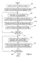
- step 102 the LPS is calibrated on a region of the wing (or other part of the aircraft) by measuring the positions of at least three known points. Then the coordinate locations of dielectric tops (or other features) to be inspected are exported from a CAD model (or other database) and transferred to the LPS (step 104). This is accomplished either through a data file or by way of a socket connection between the CAD modeling application and the LPS. The system operator then instructs the LPS to aim at the initial or next target position (step 106).
- the high-resolution, high-zoom camera of the LPS will be aimed at the specific coordinates and will capture one or more images of the current target area (step 108).
- the stored image will be read using an image processing application capable of determining if there are any anomalies in the image (step 110). More specifically, image processing software will locate anomalies (i.e. differences from the nominal) in the captured image, and then measure the length, area, or other dimensions of damage on the surface depicted in the captured image. Locations of any anomalies within the analyzed image are converted into Cartesian (X,Y,Z) coordinates in the frame of reference of the airplane coordinate system and then recorded (step 112). (Step 112 in FIG.
- step 9 may include steps 520, 522, 524, 526, 528 and 530 shown in FIG. 3 .) If multiple target locations are inspected in the scan area, the image processing steps 110 and 112 may be performed in parallel with the capture of subsequent images in steps 106 and 108. In step 114, a determination is made whether additional target points should be imaged. If Yes, then the routine returns to step 106; if No, then the system operator can instruct the LPS to aim at the initial or next anomaly position (step 116) (determined during the aforementioned image processing). The system operator then instructs the controller to activate the NDE instrument to perform NDE inspection of the current anomaly position and store the acquired NDE measurement data in a form that corresponds with the associated visual image and anomaly positions (step 118).
- the acquired data can be processed by the controller to determine the crack (or other damage) depth.
- step 120 a determination is made whether additional anomaly points should undergo NDE inspection. If Yes, then the routine returns to step 116; if No, then the NDE inspection can be terminated.
- a final check can be performed on the collected data to confirm that valid data was collected for all called for locations (not shown in FIG. 9 ). This type of check may include: (1) checking each measured position to confirm that it matches the specified position (to address the possibility of occlusions, such as an object blocking the location from view); and (2) confirming that images of the appropriate size, zoom level, and lighting levels were captured.
- the data integrity status at each location may be recorded in the database.
- the computer system that controls the inspection process can store a digital record in computer memory (or other storage medium) that correlates image data (acquired by the video camera), NDE measurement data (acquired by the NDE instrument), location on the wing (or other structure being inspected), inspection date/set-up, etc. for all dielectric tops (or other features) that were inspected.
- an inspector may select a "locate” option, in response to which the controller is programmed to cause the LPS pan-tilt unit to move, aiming and pausing at each dielectric top (or other feature under inspection) that calls for repair or removal for a duration sufficient for an inspector to manually mark those tops for follow-up.
- any one of a plurality of stand-off NDE methods can be used to measure the depth of a crack (or other damage on the aircraft), such as near-infrared spectroscopy (using a spectrograph with lensing for distance measurement), terahertz imaging (using a terahertz camera with lensing for distance measurement), stand-off infrared thermography (using a thermal imaging camera), and laser shearography (using a shearographic measurement system.
- Other methods which can be integrated with a local positioning system for stand-off NDE and positioning for composite structure include laser ultrasonic testing (using lasers to generate and detect ultrasonic waves in the component under test) and laser vibrometry (using a laser scanning vibrometer). Stand-off microwave imaging or x-ray backscatter imaging could also be used for crack depth or other damage measurements.
- Near-infrared spectroscopy is a spectroscopic method that uses the near-infrared region of the electromagnetic spectrum (with a wavelength of about 800 to about 2,500 nm).
- a focused imaging camera is used to detect radiation in the infrared range of the electromagnetic spectrum (from about 9,000 to about 14,000 nm) emitted by a selected dielectric top.
- a terahertz camera comprises an image converter configured to receive incoming terahertz radiation on a forward face and to convert the incoming radiation to visible radiation.
- the image converter includes a rigid base component made of a sapphire crystal, a thermochromic liquid crystal layer applied to a forward face of the rigid base, and a thermal absorption layer applied to the forward face of the liquid crystal.
- a visible light source may be configured to illuminate the rearward face of the converter.
- a detector adapted to detect visible light emitted from a rearward face of the converter is provided. The detector can capture a visible image formed on a rearward face of the thermochromic liquid crystal layer.
- Laser shearography is especially useful in detecting defects which are situated below a surface and not detectable using visual inspection.
- the sample under test is illuminated using a laser and imaged on a CCD camera via a special optical shearing element.
- a surface area of a selected dielectric top is illuminated with a highly coherent laser light.
- a stochastical interference pattern, called a speckle is created. This speckle can be compared to a known reference interference pattern.
- a laser pulse is directed onto the surface of a selected dielectric top through free space. That laser pulse interacts at the surface of the dielectric top to induce an ultrasonic pulse that propagates into the dielectric top.
- the ultrasonic pulse interrogates a feature of interest and then returns to the surface.
- a separate laser receiver detects the small displacement that is produced when the ultrasonic pulse reaches the surface using a measurement head.
- the means and methods disclosed hereinafter for implementing the combination of local positioning with stand-off NDE is not limited in its application to detecting cracks in dielectric tops.
- Other aircraft components can also be inspected using the techniques disclosed herein. More generally, the disclosed techniques have application in any situation where stand-off inspection of a structure is called for.
- the LPS aiming and image capture processes can run in parallel with the image processing. This is possible by designing a LPS architecture which supports distributed processing. Such a LPS unit can move, capture images, and then store the images to a mapped network drive, while a separate image processing computer (or multiple image processing computers) process the image data. In this configuration, there is no need for the system to wait at each location for the image processing to complete. By the time LPS finishes capturing the images, most of the images have already been processed to find anomalies. This also allows separate (more advanced) image processing techniques to be developed and inserted into overall system in the future. Alternatively, the image processing task can be performed on the same computer as the one controlling the other LPS functions provided that computer has sufficient processing power.
- the LPS enables the stand-off NDE methods disclosed above to have the capability of directly tying into the aircraft coordinate system and determining where damage, NDE measurement data, and repairs are located.
- the image processing software used for finding anomalies can be tuned to detect specific types of flaws.
- a manual or semi-automated sensitivity adjustment control can be implemented to allow the operator or system to adjust the size of the anomalies that are found.
- Stand-off inspection with positioning capability will increase both speed of inspection and accuracy of inspection by doing it automatically, and can do so without a robot arm or robotic crawler, thereby reducing the costs of inspection.
- computer system should be construed broadly to encompass a system having at least one computer or processor, and which may have two or more computers or processors that communicate through a network or bus.
- a position of the anomaly should be construed broadly to encompass the position of an anomaly that is a single point and the position of a single point of an anomaly that comprises multiple points (e.g., an anomaly which is a crack or an area).
Landscapes
- Physics & Mathematics (AREA)
- General Physics & Mathematics (AREA)
- Pathology (AREA)
- Health & Medical Sciences (AREA)
- Life Sciences & Earth Sciences (AREA)
- Chemical & Material Sciences (AREA)
- Analytical Chemistry (AREA)
- Biochemistry (AREA)
- General Health & Medical Sciences (AREA)
- Immunology (AREA)
- Engineering & Computer Science (AREA)
- Mathematical Physics (AREA)
- Computer Vision & Pattern Recognition (AREA)
- Signal Processing (AREA)
- Length Measuring Devices By Optical Means (AREA)
- Investigating Materials By The Use Of Optical Means Adapted For Particular Applications (AREA)
- Investigating Or Analysing Materials By Optical Means (AREA)
- Radiation Pyrometers (AREA)
- Image Processing (AREA)
- Image Analysis (AREA)
Applications Claiming Priority (1)
| Application Number | Priority Date | Filing Date | Title |
|---|---|---|---|
| US13/732,789 US9285296B2 (en) | 2013-01-02 | 2013-01-02 | Systems and methods for stand-off inspection of aircraft structures |
Publications (3)
| Publication Number | Publication Date |
|---|---|
| EP2752657A2 true EP2752657A2 (fr) | 2014-07-09 |
| EP2752657A3 EP2752657A3 (fr) | 2018-01-03 |
| EP2752657B1 EP2752657B1 (fr) | 2020-06-17 |
Family
ID=50072817
Family Applications (1)
| Application Number | Title | Priority Date | Filing Date |
|---|---|---|---|
| EP13199830.4A Active EP2752657B1 (fr) | 2013-01-02 | 2013-12-30 | Système et procédés pour inspection à distance de structures d'avion |
Country Status (3)
| Country | Link |
|---|---|
| US (1) | US9285296B2 (fr) |
| EP (1) | EP2752657B1 (fr) |
| JP (1) | JP6415034B2 (fr) |
Cited By (5)
| Publication number | Priority date | Publication date | Assignee | Title |
|---|---|---|---|---|
| CN105608695A (zh) * | 2015-12-22 | 2016-05-25 | 北京光电技术研究所 | 建筑物表面缺陷检测方法及系统 |
| CN106352910A (zh) * | 2015-07-13 | 2017-01-25 | 波音公司 | 无损检测设备的自动校准 |
| CN110081982A (zh) * | 2019-03-11 | 2019-08-02 | 中林信达(北京)科技信息有限责任公司 | 一种基于双光谱光电搜索的无人机目标定位方法 |
| CN110940420A (zh) * | 2019-11-14 | 2020-03-31 | 国网山西省电力公司大同供电公司 | 一种用于窄小管腔微型巡检机器人的温度异常点定位系统 |
| CN111684234A (zh) * | 2018-01-31 | 2020-09-18 | 富士胶片株式会社 | 修补长度的确定方法及修补长度的确定装置 |
Families Citing this family (94)
| Publication number | Priority date | Publication date | Assignee | Title |
|---|---|---|---|---|
| US9864366B2 (en) * | 2013-03-15 | 2018-01-09 | Etegent Technologies Ltd. | Manufacture modeling and monitoring |
| US11543811B2 (en) | 2013-03-15 | 2023-01-03 | Etegent Technologies Ltd. | Manufacture modeling and monitoring |
| US10162352B2 (en) | 2013-05-13 | 2018-12-25 | The Boeing Company | Remotely operated mobile stand-off measurement and inspection system |
| US10373301B2 (en) | 2013-09-25 | 2019-08-06 | Sikorsky Aircraft Corporation | Structural hot spot and critical location monitoring system and method |
| US9446860B2 (en) * | 2013-10-04 | 2016-09-20 | Airbus Operations (Sas) | Aircraft part and subassembly damage reporting method, system and mobile computer software application |
| US9488589B2 (en) * | 2013-10-29 | 2016-11-08 | The Boeing Company | Mapping damaged regions on objects |
| JP6325834B2 (ja) * | 2014-02-07 | 2018-05-16 | 三菱航空機株式会社 | 整備支援システムおよび整備支援方法 |
| US9575004B2 (en) | 2014-11-17 | 2017-02-21 | The Boeing Company | Automated low cost method for illuminating, evaluating, and qualifying surfaces and surface coatings |
| US10861147B2 (en) | 2015-01-13 | 2020-12-08 | Sikorsky Aircraft Corporation | Structural health monitoring employing physics models |
| JP6337822B2 (ja) * | 2015-04-15 | 2018-06-06 | 株式会社デンソー | 検査装置、およびプログラム |
| US9581722B2 (en) | 2015-06-02 | 2017-02-28 | Northrop Grumman Systems Corporation | Apparatus and method for noninvasively determining positioning of a component beneath a substrate |
| CN105118044B (zh) * | 2015-06-16 | 2017-11-07 | 华南理工大学 | 一种轮形铸造产品缺陷自动检测方法 |
| FR3041747B1 (fr) * | 2015-09-29 | 2019-12-27 | Safran Electronics & Defense | Procede de visee collaborative |
| DE102015119274B4 (de) * | 2015-11-09 | 2018-07-12 | Björn Habrich | Verfahren und Vorrichtung zur Bestimmung der räumlichen Position eines Gegenstandes mittels interferometrischer Längenmessung |
| DE102015120660A1 (de) * | 2015-11-27 | 2017-06-01 | Airbus Defence and Space GmbH | Luftfahrzeuginspektionssystem |
| WO2017119154A1 (fr) * | 2016-01-07 | 2017-07-13 | 三菱電機株式会社 | Dispositif et procédé de détection |
| JP2017133907A (ja) * | 2016-01-27 | 2017-08-03 | アークレイ株式会社 | 検査装置 |
| RU2630177C1 (ru) * | 2016-07-05 | 2017-09-05 | Акционерное общество "Конструкторское бюро химавтоматики" | Способ контроля качества продукции и устройство для его осуществления |
| US10260953B2 (en) * | 2016-08-11 | 2019-04-16 | The Boeing Company | Applique and method for thermographic inspection |
| TWI667618B (zh) * | 2016-11-04 | 2019-08-01 | 台灣國際物業管理顧問有限公司 | Integrated sensing positioning based on 3D information model applied to construction engineering and facility equipment management system |
| JP6213754B1 (ja) * | 2016-11-30 | 2017-10-18 | 国際航業株式会社 | 点検装置、及び点検方法 |
| CA3046651A1 (fr) | 2016-12-23 | 2018-06-28 | Gecko Robotics, Inc. | Robot d'inspection |
| US12162160B2 (en) | 2016-12-23 | 2024-12-10 | Gecko Robotics, Inc. | System, apparatus and method for improved location identification with prism |
| US12358141B2 (en) | 2016-12-23 | 2025-07-15 | Gecko Robotics, Inc. | Systems, methods, and apparatus for providing interactive inspection map for inspection robot |
| WO2018163572A1 (fr) * | 2017-03-10 | 2018-09-13 | 富士フイルム株式会社 | Système de traitement d'image, dispositif de traitement d'image, procédé de traitement d'image et programme de traitement d'image |
| US10564108B2 (en) * | 2017-07-03 | 2020-02-18 | Saudi Arabian Oil Company | Apparatus and method for nondestructively inspecting fiberglass and nonmetallic pipes |
| US10791275B2 (en) * | 2017-09-25 | 2020-09-29 | The Boeing Company | Methods for measuring and inspecting structures using cable-suspended platforms |
| DE102017219153B4 (de) * | 2017-10-25 | 2020-03-19 | Fraunhofer-Gesellschaft zur Förderung der angewandten Forschung e. V. | Vorrichtung und Verfahren zur optischen Überwachung bewegter Bauteile |
| JP6901008B2 (ja) * | 2017-12-25 | 2021-07-14 | 富士通株式会社 | 画像処理プログラム、画像処理方法、および画像処理装置 |
| JP6734583B2 (ja) * | 2018-02-23 | 2020-08-05 | 株式会社市川工務店 | 橋梁などの構造物を検査するための画像処理システム、画像処理方法及びプログラム |
| US10773817B1 (en) | 2018-03-08 | 2020-09-15 | Northrop Grumman Systems Corporation | Bi-directional flow ram air system for an aircraft |
| US10633066B2 (en) | 2018-03-27 | 2020-04-28 | The Boeing Company | Apparatus and methods for measuring positions of points on submerged surfaces |
| US11238675B2 (en) * | 2018-04-04 | 2022-02-01 | The Boeing Company | Mobile visual-inspection system |
| WO2019191819A1 (fr) * | 2018-04-05 | 2019-10-10 | Efficiency Matrix Pty Ltd | Systèmes et procédés d'audit thermique structurel mis en œuvre par ordinateur |
| US11287507B2 (en) * | 2018-04-30 | 2022-03-29 | The Boeing Company | System and method for testing a structure using laser ultrasound |
| US11268881B2 (en) | 2018-05-04 | 2022-03-08 | Raytheon Technologies Corporation | System and method for fan blade rotor disk and gear inspection |
| US10685433B2 (en) | 2018-05-04 | 2020-06-16 | Raytheon Technologies Corporation | Nondestructive coating imperfection detection system and method therefor |
| US10902664B2 (en) | 2018-05-04 | 2021-01-26 | Raytheon Technologies Corporation | System and method for detecting damage using two-dimensional imagery and three-dimensional model |
| US10928362B2 (en) | 2018-05-04 | 2021-02-23 | Raytheon Technologies Corporation | Nondestructive inspection using dual pulse-echo ultrasonics and method therefor |
| US10958843B2 (en) | 2018-05-04 | 2021-03-23 | Raytheon Technologies Corporation | Multi-camera system for simultaneous registration and zoomed imagery |
| US10488371B1 (en) * | 2018-05-04 | 2019-11-26 | United Technologies Corporation | Nondestructive inspection using thermoacoustic imagery and method therefor |
| US10943320B2 (en) | 2018-05-04 | 2021-03-09 | Raytheon Technologies Corporation | System and method for robotic inspection |
| US11079285B2 (en) | 2018-05-04 | 2021-08-03 | Raytheon Technologies Corporation | Automated analysis of thermally-sensitive coating and method therefor |
| US10914191B2 (en) | 2018-05-04 | 2021-02-09 | Raytheon Technologies Corporation | System and method for in situ airfoil inspection |
| US10473593B1 (en) | 2018-05-04 | 2019-11-12 | United Technologies Corporation | System and method for damage detection by cast shadows |
| US11270426B2 (en) * | 2018-05-14 | 2022-03-08 | Sri International | Computer aided inspection system and methods |
| JP7131127B2 (ja) * | 2018-06-27 | 2022-09-06 | オムロン株式会社 | 外観検査システム、外観検査結果の表示方法、および、外観検査結果の表示プログラム |
| JP7070153B2 (ja) * | 2018-06-27 | 2022-05-18 | オムロン株式会社 | 外観検査システム、外観検査結果の表示方法、および、外観検査結果の表示プログラム |
| JP7403834B2 (ja) * | 2018-07-17 | 2023-12-25 | 株式会社Synapse Gear | 撮像装置と撮像方法 |
| US10546371B1 (en) * | 2018-08-22 | 2020-01-28 | William Pyznar | System and method for inspecting the condition of structures using remotely controlled devices |
| DE102018122965B4 (de) * | 2018-09-19 | 2021-10-14 | INOEX GmbH Innovationen und Ausrüstungen für die Extrusionstechnik | THz-Messgerät und THz-Messverfahren zur Ermittlung von Fehlstellen in Messobjekten |
| KR102215235B1 (ko) * | 2018-09-20 | 2021-02-15 | 한국항공우주산업 주식회사 | 항공기 형상모델의 단면 절단 좌표 추출 방법 |
| CN109684709B (zh) * | 2018-12-20 | 2022-12-30 | 中国民航大学 | 一种航空发动机叶片修复的自适应定位方法 |
| US11630083B2 (en) * | 2018-12-21 | 2023-04-18 | The Boeing Company | Location-based scanner repositioning using non-destructive inspection |
| EP3904838A4 (fr) | 2018-12-27 | 2022-08-24 | HORIBA, Ltd. | Système de mesure, dispositif de mesure, procédé de mesure et programme |
| US11275391B2 (en) | 2019-05-13 | 2022-03-15 | The Boeing Company | In-service maintenance process using unmanned aerial vehicles |
| JP7188596B2 (ja) * | 2019-07-19 | 2022-12-13 | 株式会社島津製作所 | 航空機検査支援装置および航空機検査支援方法 |
| FR3099753B1 (fr) * | 2019-08-07 | 2021-09-03 | Safran Aircraft Engines | Procede de surveillance, produit programme d’ordinateur, systeme de surveillance et aeronef associes |
| CN110514664B (zh) * | 2019-08-20 | 2022-08-12 | 北京信息科技大学 | 一种筒子纱纱杆定位检测机器人及方法 |
| CN110748779A (zh) * | 2019-11-21 | 2020-02-04 | 大连海洋大学 | 一种光纤线缆远距离探测辅助杆及使用方法 |
| CN111158358B (zh) * | 2019-11-29 | 2022-11-11 | 中国电力科学研究院有限公司 | 一种基于三维模型对变电/换流站自优巡检的方法及系统 |
| US20210185295A1 (en) * | 2019-12-17 | 2021-06-17 | Koninklijke Philips N.V. | Device and method for assisting in 3d scanning a subject |
| US11630459B2 (en) | 2020-01-29 | 2023-04-18 | The Boeing Company | Repair of structures using unmanned aerial vehicles |
| US11891174B2 (en) | 2020-02-05 | 2024-02-06 | The Boeing Company | Repair of structures using unmanned aerial vehicles |
| US11529777B2 (en) | 2020-02-05 | 2022-12-20 | The Boeing Company | Hot bond repair of structures using unmanned aerial vehicles |
| US11555693B2 (en) | 2020-05-12 | 2023-01-17 | The Boeing Company | Measurement of surface profiles using unmanned aerial vehicles |
| US11745872B2 (en) | 2020-06-19 | 2023-09-05 | The Boeing Company | Methods for marking surfaces using unmanned aerial vehicles |
| CN112014404A (zh) * | 2020-08-27 | 2020-12-01 | Oppo(重庆)智能科技有限公司 | 组件检测方法、装置、系统、电子设备及存储介质 |
| CN112623262B (zh) * | 2020-12-30 | 2023-02-28 | 中航贵州飞机有限责任公司 | 一种装配工装安装检修方法 |
| WO2022164885A1 (fr) * | 2021-01-26 | 2022-08-04 | American Robotics, Inc. | Procédés et systèmes pour la réalisation d'inspections pré-vol à distance de drone |
| BR112023015265A2 (pt) | 2021-01-28 | 2023-11-07 | Scoutcam Ltd | Sistema para monitorar falhas em potencial em uma máquina ou um componente da mesma e método implementado por computador para monitorar uma máquina ou um componente da mesma |
| WO2022225725A1 (fr) | 2021-04-20 | 2022-10-27 | Gecko Robotics, Inc. | Robot d'inspection flexible |
| US12566158B2 (en) | 2021-04-22 | 2026-03-03 | Gecko Robotics, Inc. | Robotic systems for ultrasonic surface inspection using shaped elements |
| CA3173120A1 (fr) | 2021-04-22 | 2022-10-22 | Chase David | Systemes, methodes et appareil pour l'inspection ultrasonique d'une surface |
| JP7675325B2 (ja) * | 2021-05-20 | 2025-05-13 | 京セラドキュメントソリューションズ株式会社 | 画像処理装置 |
| US12269220B2 (en) * | 2021-05-28 | 2025-04-08 | Wichita State University | Joint autonomous repair verification and inspection system |
| US11502729B1 (en) * | 2021-08-10 | 2022-11-15 | The Boeing Company | Methods for through-structure power and data transfer between mobile robots and sensor nodes |
| US12600041B2 (en) * | 2021-10-25 | 2026-04-14 | Wichita State University | Surface analyst end effector for industrial robot |
| CN114137636B (zh) * | 2021-11-11 | 2022-08-12 | 四川九通智路科技有限公司 | 一种环形压力传感器的区域气象监测管理方法及系统 |
| IL316571A (en) | 2022-04-27 | 2024-12-01 | Odysight Ai Ltd | Monitoring a mechanism or component of a mechanism |
| CN115108043B (zh) * | 2022-06-22 | 2025-07-22 | 沈阳飞机工业(集团)有限公司 | 飞机一体化结构数字化修配系统及方法 |
| US20240027420A1 (en) * | 2022-07-20 | 2024-01-25 | The Boeing Company | System and method for inspecting components fabricated using a powder metallurgy process |
| US12304091B2 (en) | 2022-08-10 | 2025-05-20 | Wilder Systems, Inc. | Training of artificial intelligence model |
| US11931910B2 (en) | 2022-08-10 | 2024-03-19 | Wilder Systems Inc. | Use of artificial intelligence models to identify fasteners and perform related operations |
| WO2024097795A2 (fr) | 2022-11-01 | 2024-05-10 | Gecko Robotics, Inc. | Robot d'inspection avec traîneau d'adaptation de profil, film de réduction de couplant et nacelle de transducteur pour actifs épais |
| CN116045807B (zh) * | 2022-12-29 | 2025-07-25 | 易思维(杭州)科技股份有限公司 | 一种兼容多型号待测工件的视觉检测方法、系统及其应用 |
| CN120916868A (zh) * | 2023-01-25 | 2025-11-07 | 威尔德系统公司 | 使用人工智能模型标识紧固件并进行相关操作 |
| US12523355B2 (en) * | 2023-03-31 | 2026-01-13 | Electronic Theatre Controls, Inc. | Focus assistance for rotating luminaire based on measurements by independently rotating distance sensor |
| US12596295B2 (en) | 2023-03-31 | 2026-04-07 | Electronic Theatre Controls, Inc. | Range-based focus assistance for projection optics |
| US20250078463A1 (en) * | 2023-09-05 | 2025-03-06 | The Boeing Company | Region-based object detection with contextual information |
| CN118278096B (zh) * | 2024-01-26 | 2024-10-11 | 中国电子产品可靠性与环境试验研究所((工业和信息化部电子第五研究所)(中国赛宝实验室)) | 部件安全性检查方法、装置、设备、存储介质和程序产品 |
| GB2639541A (en) * | 2024-02-22 | 2025-10-01 | Airbus Operations Ltd | Aircraft fuel tank fastener inspection |
| JP2025154035A (ja) * | 2024-03-29 | 2025-10-10 | 直人 榊原 | 温熱環境計測装置及びそれを用いた温熱環境解析方法 |
| CN120760594B (zh) * | 2025-09-09 | 2025-12-12 | 成都飞机工业(集团)有限责任公司 | 一种用于飞机定位的激光跟踪仪厂房靶球布局评价方法 |
Family Cites Families (13)
| Publication number | Priority date | Publication date | Assignee | Title |
|---|---|---|---|---|
| US4628402A (en) | 1985-09-30 | 1986-12-09 | The Boeing Company | Lightning protection of fasteners in composite material |
| US6433867B1 (en) * | 2000-01-11 | 2002-08-13 | The Aerospace Corporation | Contrast imaging method for inspecting specular surface devices |
| GB0008303D0 (en) * | 2000-04-06 | 2000-05-24 | British Aerospace | Measurement system and method |
| US6542849B2 (en) * | 2001-01-19 | 2003-04-01 | The University Of Chicago | Method for determining defect depth using thermal imaging |
| US7499772B2 (en) * | 2005-08-31 | 2009-03-03 | Honeywell International Inc. | Method and system for navigating a nondestructive evaluation device |
| JP2007316019A (ja) * | 2006-05-29 | 2007-12-06 | Daihatsu Motor Co Ltd | 表面欠陥検査装置 |
| US7859655B2 (en) | 2007-09-28 | 2010-12-28 | The Boeing Company | Method involving a pointing instrument and a target object |
| US8044991B2 (en) * | 2007-09-28 | 2011-10-25 | The Boeing Company | Local positioning system and method |
| US8249832B2 (en) | 2009-12-05 | 2012-08-21 | The Boeing Company | Correlation of inspection information and computer-aided design data for structural assessment |
| US9182487B2 (en) | 2011-06-22 | 2015-11-10 | The Boeing Company | Advanced remote nondestructive inspection system and process |
| US8982207B2 (en) * | 2010-10-04 | 2015-03-17 | The Boeing Company | Automated visual inspection system |
| US8713998B2 (en) * | 2011-06-14 | 2014-05-06 | The Boeing Company | Autonomous non-destructive evaluation system for aircraft structures |
| US8738226B2 (en) | 2011-07-18 | 2014-05-27 | The Boeing Company | Holonomic motion vehicle for travel on non-level surfaces |
-
2013
- 2013-01-02 US US13/732,789 patent/US9285296B2/en active Active
- 2013-10-31 JP JP2013227017A patent/JP6415034B2/ja active Active
- 2013-12-30 EP EP13199830.4A patent/EP2752657B1/fr active Active
Cited By (10)
| Publication number | Priority date | Publication date | Assignee | Title |
|---|---|---|---|---|
| CN106352910A (zh) * | 2015-07-13 | 2017-01-25 | 波音公司 | 无损检测设备的自动校准 |
| EP3118618A3 (fr) * | 2015-07-13 | 2017-04-19 | The Boeing Company | Étalonnage automatique d'un équipement d'essai non destructif |
| US10345272B2 (en) | 2015-07-13 | 2019-07-09 | The Boeing Company | Automated calibration of non-destructive testing equipment |
| CN105608695A (zh) * | 2015-12-22 | 2016-05-25 | 北京光电技术研究所 | 建筑物表面缺陷检测方法及系统 |
| CN111684234A (zh) * | 2018-01-31 | 2020-09-18 | 富士胶片株式会社 | 修补长度的确定方法及修补长度的确定装置 |
| US11263739B2 (en) | 2018-01-31 | 2022-03-01 | Fujifilm Corporation | Repair length determination method and repair length determination apparatus |
| CN111684234B (zh) * | 2018-01-31 | 2022-04-26 | 富士胶片株式会社 | 修补长度的确定方法及修补长度的确定装置 |
| CN110081982A (zh) * | 2019-03-11 | 2019-08-02 | 中林信达(北京)科技信息有限责任公司 | 一种基于双光谱光电搜索的无人机目标定位方法 |
| CN110940420A (zh) * | 2019-11-14 | 2020-03-31 | 国网山西省电力公司大同供电公司 | 一种用于窄小管腔微型巡检机器人的温度异常点定位系统 |
| CN110940420B (zh) * | 2019-11-14 | 2021-06-22 | 国网山西省电力公司大同供电公司 | 一种用于窄小管腔微型巡检机器人的温度异常点定位系统 |
Also Published As
| Publication number | Publication date |
|---|---|
| JP6415034B2 (ja) | 2018-10-31 |
| US20140184786A1 (en) | 2014-07-03 |
| EP2752657A3 (fr) | 2018-01-03 |
| US9285296B2 (en) | 2016-03-15 |
| JP2014132437A (ja) | 2014-07-17 |
| EP2752657B1 (fr) | 2020-06-17 |
Similar Documents
| Publication | Publication Date | Title |
|---|---|---|
| EP2752657B1 (fr) | Système et procédés pour inspection à distance de structures d'avion | |
| US12347575B2 (en) | Systems and methods for laser inspection and measurements | |
| US11629957B2 (en) | Surveying apparatus | |
| CN1226865C (zh) | 识别在空间的对象的方法及对红外辐射敏感的红外摄像机 | |
| US20140132729A1 (en) | Method and apparatus for camera-based 3d flaw tracking system | |
| JP5337805B2 (ja) | 局所的位置決定システムとその方法 | |
| US10634632B2 (en) | Methods for inspecting structures having non-planar surfaces using location alignment feedback | |
| US9488592B1 (en) | Automatic detection of defects in composite structures using NDT methods | |
| KR101028060B1 (ko) | 열화상 인식을 이용한 전력설비 열화 측정장치 및 방법 | |
| US20170052070A1 (en) | Rapid Automated Infrared Thermography for Inspecting Large Composite Structures | |
| US9804577B1 (en) | Remotely operated mobile stand-off measurement and inspection system | |
| JP6039050B1 (ja) | 無人機を用いた構造物等の検査方法 | |
| US10497109B2 (en) | Time-lapse infrared thermography system and method for damage detection in large-scale objects | |
| WO2015065660A1 (fr) | Mappage de régions endommagées sur des objets | |
| TW201009292A (en) | Vision system for scan planning of ultrasonic inspection | |
| US12030670B2 (en) | Aircraft inspection support device and aircraft inspection support method | |
| TW201300634A (zh) | 轉子葉片之評測 | |
| CN114323571A (zh) | 一种光电瞄准系统多光轴一致性检测方法 | |
| JP2022151763A (ja) | 航空機構造体の損傷の自動評価 | |
| CN114838668A (zh) | 一种隧道位移监测方法及系统 | |
| US8379081B2 (en) | Appearance inspection apparatus and appearance inspection method | |
| KR101520018B1 (ko) | 터널점검장치 | |
| Hess et al. | High-resolution thermal imaging methodology for non-destructive evaluation of historic structures | |
| CN110260889B (zh) | 一种手持式测距仪自动检定装置及其检定方法 | |
| US5283642A (en) | Scratch measurement apparatus and method |
Legal Events
| Date | Code | Title | Description |
|---|---|---|---|
| 17P | Request for examination filed |
Effective date: 20131230 |
|
| AK | Designated contracting states |
Kind code of ref document: A2 Designated state(s): AL AT BE BG CH CY CZ DE DK EE ES FI FR GB GR HR HU IE IS IT LI LT LU LV MC MK MT NL NO PL PT RO RS SE SI SK SM TR |
|
| AX | Request for extension of the european patent |
Extension state: BA ME |
|
| PUAI | Public reference made under article 153(3) epc to a published international application that has entered the european phase |
Free format text: ORIGINAL CODE: 0009012 |
|
| PUAL | Search report despatched |
Free format text: ORIGINAL CODE: 0009013 |
|
| AK | Designated contracting states |
Kind code of ref document: A3 Designated state(s): AL AT BE BG CH CY CZ DE DK EE ES FI FR GB GR HR HU IE IS IT LI LT LU LV MC MK MT NL NO PL PT RO RS SE SI SK SM TR |
|
| AX | Request for extension of the european patent |
Extension state: BA ME |
|
| RIC1 | Information provided on ipc code assigned before grant |
Ipc: G01N 21/84 20060101ALI20171129BHEP Ipc: G01N 21/88 20060101AFI20171129BHEP |
|
| STAA | Information on the status of an ep patent application or granted ep patent |
Free format text: STATUS: REQUEST FOR EXAMINATION WAS MADE |
|
| R17P | Request for examination filed (corrected) |
Effective date: 20180627 |
|
| RBV | Designated contracting states (corrected) |
Designated state(s): AL AT BE BG CH CY CZ DE DK EE ES FI FR GB GR HR HU IE IS IT LI LT LU LV MC MK MT NL NO PL PT RO RS SE SI SK SM TR |
|
| GRAP | Despatch of communication of intention to grant a patent |
Free format text: ORIGINAL CODE: EPIDOSNIGR1 |
|
| STAA | Information on the status of an ep patent application or granted ep patent |
Free format text: STATUS: GRANT OF PATENT IS INTENDED |
|
| INTG | Intention to grant announced |
Effective date: 20190909 |
|
| GRAJ | Information related to disapproval of communication of intention to grant by the applicant or resumption of examination proceedings by the epo deleted |
Free format text: ORIGINAL CODE: EPIDOSDIGR1 |
|
| STAA | Information on the status of an ep patent application or granted ep patent |
Free format text: STATUS: REQUEST FOR EXAMINATION WAS MADE |
|
| GRAP | Despatch of communication of intention to grant a patent |
Free format text: ORIGINAL CODE: EPIDOSNIGR1 |
|
| STAA | Information on the status of an ep patent application or granted ep patent |
Free format text: STATUS: GRANT OF PATENT IS INTENDED |
|
| INTC | Intention to grant announced (deleted) | ||
| INTG | Intention to grant announced |
Effective date: 20200108 |
|
| GRAS | Grant fee paid |
Free format text: ORIGINAL CODE: EPIDOSNIGR3 |
|
| GRAA | (expected) grant |
Free format text: ORIGINAL CODE: 0009210 |
|
| STAA | Information on the status of an ep patent application or granted ep patent |
Free format text: STATUS: THE PATENT HAS BEEN GRANTED |
|
| AK | Designated contracting states |
Kind code of ref document: B1 Designated state(s): AL AT BE BG CH CY CZ DE DK EE ES FI FR GB GR HR HU IE IS IT LI LT LU LV MC MK MT NL NO PL PT RO RS SE SI SK SM TR |
|
| REG | Reference to a national code |
Ref country code: GB Ref legal event code: FG4D |
|
| REG | Reference to a national code |
Ref country code: CH Ref legal event code: EP |
|
| REG | Reference to a national code |
Ref country code: DE Ref legal event code: R096 Ref document number: 602013069892 Country of ref document: DE |
|
| REG | Reference to a national code |
Ref country code: IE Ref legal event code: FG4D |
|
| REG | Reference to a national code |
Ref country code: AT Ref legal event code: REF Ref document number: 1281927 Country of ref document: AT Kind code of ref document: T Effective date: 20200715 |
|
| PG25 | Lapsed in a contracting state [announced via postgrant information from national office to epo] |
Ref country code: SE Free format text: LAPSE BECAUSE OF FAILURE TO SUBMIT A TRANSLATION OF THE DESCRIPTION OR TO PAY THE FEE WITHIN THE PRESCRIBED TIME-LIMIT Effective date: 20200617 Ref country code: NO Free format text: LAPSE BECAUSE OF FAILURE TO SUBMIT A TRANSLATION OF THE DESCRIPTION OR TO PAY THE FEE WITHIN THE PRESCRIBED TIME-LIMIT Effective date: 20200917 Ref country code: GR Free format text: LAPSE BECAUSE OF FAILURE TO SUBMIT A TRANSLATION OF THE DESCRIPTION OR TO PAY THE FEE WITHIN THE PRESCRIBED TIME-LIMIT Effective date: 20200918 Ref country code: FI Free format text: LAPSE BECAUSE OF FAILURE TO SUBMIT A TRANSLATION OF THE DESCRIPTION OR TO PAY THE FEE WITHIN THE PRESCRIBED TIME-LIMIT Effective date: 20200617 Ref country code: LT Free format text: LAPSE BECAUSE OF FAILURE TO SUBMIT A TRANSLATION OF THE DESCRIPTION OR TO PAY THE FEE WITHIN THE PRESCRIBED TIME-LIMIT Effective date: 20200617 |
|
| REG | Reference to a national code |
Ref country code: LT Ref legal event code: MG4D |
|
| REG | Reference to a national code |
Ref country code: NL Ref legal event code: MP Effective date: 20200617 |
|
| PG25 | Lapsed in a contracting state [announced via postgrant information from national office to epo] |
Ref country code: HR Free format text: LAPSE BECAUSE OF FAILURE TO SUBMIT A TRANSLATION OF THE DESCRIPTION OR TO PAY THE FEE WITHIN THE PRESCRIBED TIME-LIMIT Effective date: 20200617 Ref country code: RS Free format text: LAPSE BECAUSE OF FAILURE TO SUBMIT A TRANSLATION OF THE DESCRIPTION OR TO PAY THE FEE WITHIN THE PRESCRIBED TIME-LIMIT Effective date: 20200617 Ref country code: LV Free format text: LAPSE BECAUSE OF FAILURE TO SUBMIT A TRANSLATION OF THE DESCRIPTION OR TO PAY THE FEE WITHIN THE PRESCRIBED TIME-LIMIT Effective date: 20200617 Ref country code: BG Free format text: LAPSE BECAUSE OF FAILURE TO SUBMIT A TRANSLATION OF THE DESCRIPTION OR TO PAY THE FEE WITHIN THE PRESCRIBED TIME-LIMIT Effective date: 20200917 |
|
| REG | Reference to a national code |
Ref country code: AT Ref legal event code: MK05 Ref document number: 1281927 Country of ref document: AT Kind code of ref document: T Effective date: 20200617 |
|
| PG25 | Lapsed in a contracting state [announced via postgrant information from national office to epo] |
Ref country code: NL Free format text: LAPSE BECAUSE OF FAILURE TO SUBMIT A TRANSLATION OF THE DESCRIPTION OR TO PAY THE FEE WITHIN THE PRESCRIBED TIME-LIMIT Effective date: 20200617 Ref country code: AL Free format text: LAPSE BECAUSE OF FAILURE TO SUBMIT A TRANSLATION OF THE DESCRIPTION OR TO PAY THE FEE WITHIN THE PRESCRIBED TIME-LIMIT Effective date: 20200617 |
|
| PG25 | Lapsed in a contracting state [announced via postgrant information from national office to epo] |
Ref country code: IT Free format text: LAPSE BECAUSE OF FAILURE TO SUBMIT A TRANSLATION OF THE DESCRIPTION OR TO PAY THE FEE WITHIN THE PRESCRIBED TIME-LIMIT Effective date: 20200617 Ref country code: CZ Free format text: LAPSE BECAUSE OF FAILURE TO SUBMIT A TRANSLATION OF THE DESCRIPTION OR TO PAY THE FEE WITHIN THE PRESCRIBED TIME-LIMIT Effective date: 20200617 Ref country code: RO Free format text: LAPSE BECAUSE OF FAILURE TO SUBMIT A TRANSLATION OF THE DESCRIPTION OR TO PAY THE FEE WITHIN THE PRESCRIBED TIME-LIMIT Effective date: 20200617 Ref country code: PT Free format text: LAPSE BECAUSE OF FAILURE TO SUBMIT A TRANSLATION OF THE DESCRIPTION OR TO PAY THE FEE WITHIN THE PRESCRIBED TIME-LIMIT Effective date: 20201019 Ref country code: ES Free format text: LAPSE BECAUSE OF FAILURE TO SUBMIT A TRANSLATION OF THE DESCRIPTION OR TO PAY THE FEE WITHIN THE PRESCRIBED TIME-LIMIT Effective date: 20200617 Ref country code: EE Free format text: LAPSE BECAUSE OF FAILURE TO SUBMIT A TRANSLATION OF THE DESCRIPTION OR TO PAY THE FEE WITHIN THE PRESCRIBED TIME-LIMIT Effective date: 20200617 Ref country code: AT Free format text: LAPSE BECAUSE OF FAILURE TO SUBMIT A TRANSLATION OF THE DESCRIPTION OR TO PAY THE FEE WITHIN THE PRESCRIBED TIME-LIMIT Effective date: 20200617 Ref country code: SM Free format text: LAPSE BECAUSE OF FAILURE TO SUBMIT A TRANSLATION OF THE DESCRIPTION OR TO PAY THE FEE WITHIN THE PRESCRIBED TIME-LIMIT Effective date: 20200617 |
|
| PG25 | Lapsed in a contracting state [announced via postgrant information from national office to epo] |
Ref country code: IS Free format text: LAPSE BECAUSE OF FAILURE TO SUBMIT A TRANSLATION OF THE DESCRIPTION OR TO PAY THE FEE WITHIN THE PRESCRIBED TIME-LIMIT Effective date: 20201017 Ref country code: PL Free format text: LAPSE BECAUSE OF FAILURE TO SUBMIT A TRANSLATION OF THE DESCRIPTION OR TO PAY THE FEE WITHIN THE PRESCRIBED TIME-LIMIT Effective date: 20200617 Ref country code: SK Free format text: LAPSE BECAUSE OF FAILURE TO SUBMIT A TRANSLATION OF THE DESCRIPTION OR TO PAY THE FEE WITHIN THE PRESCRIBED TIME-LIMIT Effective date: 20200617 |
|
| REG | Reference to a national code |
Ref country code: DE Ref legal event code: R097 Ref document number: 602013069892 Country of ref document: DE |
|
| PLBE | No opposition filed within time limit |
Free format text: ORIGINAL CODE: 0009261 |
|
| STAA | Information on the status of an ep patent application or granted ep patent |
Free format text: STATUS: NO OPPOSITION FILED WITHIN TIME LIMIT |
|
| PG25 | Lapsed in a contracting state [announced via postgrant information from national office to epo] |
Ref country code: DK Free format text: LAPSE BECAUSE OF FAILURE TO SUBMIT A TRANSLATION OF THE DESCRIPTION OR TO PAY THE FEE WITHIN THE PRESCRIBED TIME-LIMIT Effective date: 20200617 |
|
| 26N | No opposition filed |
Effective date: 20210318 |
|
| PG25 | Lapsed in a contracting state [announced via postgrant information from national office to epo] |
Ref country code: SI Free format text: LAPSE BECAUSE OF FAILURE TO SUBMIT A TRANSLATION OF THE DESCRIPTION OR TO PAY THE FEE WITHIN THE PRESCRIBED TIME-LIMIT Effective date: 20200617 |
|
| REG | Reference to a national code |
Ref country code: CH Ref legal event code: PL |
|
| PG25 | Lapsed in a contracting state [announced via postgrant information from national office to epo] |
Ref country code: MC Free format text: LAPSE BECAUSE OF FAILURE TO SUBMIT A TRANSLATION OF THE DESCRIPTION OR TO PAY THE FEE WITHIN THE PRESCRIBED TIME-LIMIT Effective date: 20200617 |
|
| REG | Reference to a national code |
Ref country code: BE Ref legal event code: MM Effective date: 20201231 |
|
| PG25 | Lapsed in a contracting state [announced via postgrant information from national office to epo] |
Ref country code: IE Free format text: LAPSE BECAUSE OF NON-PAYMENT OF DUE FEES Effective date: 20201230 Ref country code: LU Free format text: LAPSE BECAUSE OF NON-PAYMENT OF DUE FEES Effective date: 20201230 |
|
| PG25 | Lapsed in a contracting state [announced via postgrant information from national office to epo] |
Ref country code: LI Free format text: LAPSE BECAUSE OF NON-PAYMENT OF DUE FEES Effective date: 20201231 Ref country code: CH Free format text: LAPSE BECAUSE OF NON-PAYMENT OF DUE FEES Effective date: 20201231 |
|
| PG25 | Lapsed in a contracting state [announced via postgrant information from national office to epo] |
Ref country code: TR Free format text: LAPSE BECAUSE OF FAILURE TO SUBMIT A TRANSLATION OF THE DESCRIPTION OR TO PAY THE FEE WITHIN THE PRESCRIBED TIME-LIMIT Effective date: 20200617 Ref country code: MT Free format text: LAPSE BECAUSE OF FAILURE TO SUBMIT A TRANSLATION OF THE DESCRIPTION OR TO PAY THE FEE WITHIN THE PRESCRIBED TIME-LIMIT Effective date: 20200617 Ref country code: CY Free format text: LAPSE BECAUSE OF FAILURE TO SUBMIT A TRANSLATION OF THE DESCRIPTION OR TO PAY THE FEE WITHIN THE PRESCRIBED TIME-LIMIT Effective date: 20200617 |
|
| PG25 | Lapsed in a contracting state [announced via postgrant information from national office to epo] |
Ref country code: MK Free format text: LAPSE BECAUSE OF FAILURE TO SUBMIT A TRANSLATION OF THE DESCRIPTION OR TO PAY THE FEE WITHIN THE PRESCRIBED TIME-LIMIT Effective date: 20200617 |
|
| PG25 | Lapsed in a contracting state [announced via postgrant information from national office to epo] |
Ref country code: BE Free format text: LAPSE BECAUSE OF NON-PAYMENT OF DUE FEES Effective date: 20201231 |
|
| P01 | Opt-out of the competence of the unified patent court (upc) registered |
Effective date: 20230516 |
|
| PGFP | Annual fee paid to national office [announced via postgrant information from national office to epo] |
Ref country code: GB Payment date: 20251229 Year of fee payment: 13 |
|
| PGFP | Annual fee paid to national office [announced via postgrant information from national office to epo] |
Ref country code: FR Payment date: 20251226 Year of fee payment: 13 |
|
| PGFP | Annual fee paid to national office [announced via postgrant information from national office to epo] |
Ref country code: DE Payment date: 20251229 Year of fee payment: 13 |