EP2753145A2 - Appareil de cuisson à induction - Google Patents
Appareil de cuisson à induction Download PDFInfo
- Publication number
- EP2753145A2 EP2753145A2 EP13199745.4A EP13199745A EP2753145A2 EP 2753145 A2 EP2753145 A2 EP 2753145A2 EP 13199745 A EP13199745 A EP 13199745A EP 2753145 A2 EP2753145 A2 EP 2753145A2
- Authority
- EP
- European Patent Office
- Prior art keywords
- switch
- cooking apparatus
- induction heat
- heat cooking
- inverter
- Prior art date
- Legal status (The legal status is an assumption and is not a legal conclusion. Google has not performed a legal analysis and makes no representation as to the accuracy of the status listed.)
- Granted
Links
Images


Classifications
-
- H—ELECTRICITY
- H05—ELECTRIC TECHNIQUES NOT OTHERWISE PROVIDED FOR
- H05B—ELECTRIC HEATING; ELECTRIC LIGHT SOURCES NOT OTHERWISE PROVIDED FOR; CIRCUIT ARRANGEMENTS FOR ELECTRIC LIGHT SOURCES, IN GENERAL
- H05B6/00—Heating by electric, magnetic or electromagnetic fields
- H05B6/02—Induction heating
- H05B6/06—Control, e.g. of temperature, of power
-
- H—ELECTRICITY
- H05—ELECTRIC TECHNIQUES NOT OTHERWISE PROVIDED FOR
- H05B—ELECTRIC HEATING; ELECTRIC LIGHT SOURCES NOT OTHERWISE PROVIDED FOR; CIRCUIT ARRANGEMENTS FOR ELECTRIC LIGHT SOURCES, IN GENERAL
- H05B6/00—Heating by electric, magnetic or electromagnetic fields
- H05B6/02—Induction heating
- H05B6/06—Control, e.g. of temperature, of power
- H05B6/062—Control, e.g. of temperature, of power for cooking plates or the like
- H05B6/065—Control, e.g. of temperature, of power for cooking plates or the like using coordinated control of multiple induction coils
Definitions
- the present disclosure relates to an induction heat cooking apparatus, and more particularly, to an induction heat cooking apparatus including an inverter, which is constituted by three switching devices, and two resonant circuits.
- Induction heat cooking apparatuses having inverters are known. However, they suffer from various disadvantages.
- induction heat cooking apparatuses are electrical cooking apparatuses in which high-frequency current flows into a heating element (e.g., working coil or heating coil), and thus eddy current flows while a strong magnetic flux generated due to the flowing of the high-frequency current passes through a cooking container to heat the container itself, thereby performing a cooking function.
- a heating element e.g., working coil or heating coil
- An inverter used in the induction heat cooking apparatus serves as a switching device for switching a voltage applied to the heating coil so that the high-frequency current flows into the heating coil.
- the inverter may operate a switching device constituted by a general insulate gate bipolar transistor (IGBT) to allow high-frequency current to flow into the heating coil, thereby generating high-frequency magnetic fields around the heating coil.
- IGBT general insulate gate bipolar transistor
- two inverters are needed to operate the two heating coil at the same time. Also, although the two heating coils are provided in the induction heat cooking apparatus, if one inverter is provided, a separate switch may be provided to selectively operate only one of the two heating coils.
- Figure 1 is a view of an induction heat cooking apparatus according to one embodiment.
- the induction heat cooking apparatus includes two inverters and two heating coils.
- an induction heat cooking apparatus includes a rectifying part 10, a first inverter 20, a second inverter 30, a first heating coil 40, a second heating coil 50, a first resonant capacitor 60, and a second resonant capacitor 70.
- the first and second inverters 20 and 30 are respectively connected to switching devices for switching input power in series.
- the first and second heating coils 40 and 50 operated by an output voltage of each of the switching devices are respectively connected to contact points of the switching devices that are respectively connected to the first and second heating coils 40 and 50 in series.
- the first and second heating coils 40 and 50 have the other sides respectively connected to the resonant capacitors 60 and 70.
- each of the switching devices may be performed by a driving part.
- a switching time outputted from each of the driving parts may be controlled to apply a high-frequency voltage to the heating coils while the switching devices are alternately operated. Since a closing/opening time of the switching device applied from the driving part is controlled to gradually compensate the closing/opening time, a voltage supplied into each of the heating coils may be converted from a low voltage to a high voltage.
- the induction heat cooking apparatus should include two inverter circuits to operate the two heating coils.
- one disadvantage in this embodiment is that the product may increase in volume as well as price due to multiple inverter circuits that are required.
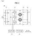
- Figure 2 is circuit diagram of an induction heat cooking apparatus according to an embodiment.
- an induction heat cooking apparatus 200 includes a rectifying part 210 receiving a commercial power AC from the outside to rectify the received commercial power into a DC voltage and an inverter 220 (S1, S2, and S3) connected between a positive power terminal and a negative power terminal in series to switch the terminals according to a control signal, thereby providing a resonant voltage.
- an induction heat cooking apparatus 200 includes a rectifying part 210 receiving a commercial power AC from the outside to rectify the received commercial power into a DC voltage, an inverter 220 (S1, S2, and S3) connected between a positive power terminal and a negative power terminal in series to switch the terminals according to a control signal, thereby providing a resonant voltage, a first heating coil 230 connected to an outer terminal of the inverter 220, a second heating coil 240 connected to the output terminal of the inverter 220 and connected to the first heating coil 230 in parallel, a first resonant capacitor 250 connected to an outer terminal of the first heating coil 230 and including a plurality of capacitors connected to each other in parallel, a second resonant capacitor 260 connected to an output terminal of the second heating coil 240 and including a plurality of capacitors connected to each other in parallel, a switching signal generation part 270 supplying a switching signal into each of switches S1, S2, and S3 provided in the inverter 220
- an unexplained capacitor may represent a smoothing capacitor.
- the smoothing capacitor may allow a pulsating DC voltage rectified in the rectifying part 210 to be smooth, thereby generate a constant DC voltage.
- the rectifying part 210 includes a first rectifying part D1, a second rectifying part D2, a third rectifying part D3, and a fourth rectifying part D4.
- the first rectifying part D1 and the third rectifying part D3 are connected to each other in serial.
- the second rectifying part D2 and the fourth rectifying part D4 are connected to each other in series.
- the inverter 220 includes a plurality of switches.
- the inverter 220 may include a first switch S1, a second switch S2, and a third switch S3.
- the first switch S1 has one end connected to the positive power terminal and the other end connected to an end of the second switch S2.
- the second switch S2 has one end connected to the other end of the first switch S1 and the other end connected to one end of the third switch S3.
- the third switch S3 has one end connected to the other end of the second switch S2 and the other end connected to the negative power terminal.
- the first heating coil 230 has one end connected to a contact point between the other end of the first switch S1 and one end of the second switch S2 and the other end connected to the plurality of capacitors included in the first resonant capacitor 250 (Cr11 and Cr12).
- the second heating coil 240 has one end connected to a contact point between the other end of the second switch S2 and one end of the third switch S3 and the other end connected to the plurality of capacitors included in the second resonant capacitor 260 (Cr21 and Cr22).
- the first heating coil 230 and the first resonant capacitor 250 constitute a first resonant circuit to serve as a first burner.
- the second heating coil 240 and the second resonant capacitor 260 constitute a second resonant circuit to serve as a second burner.
- An anti-parallel diode is connected to each of the switches S1, S2, and S3 included in the inverter 220. Also, an auxiliary resonant capacitor parallely connected to the anti-parallel diode for minimizing a switching loss of each of the switches is connected to the each of the switches S1, S2, and S3.
- the switching signal generation part 270 is connected to a gate terminal of each of the first, second, and third switches of the inverter 220. Thus, the switching signal generation part 270 outputs a gate signal for controlling a switching state of each of the first, second, and third switches S1, S2, and S3.
- the gate signal may be a switching signal for determining the switching state of each of the first, second, and third switches S1, S2, and S3.
- the switching signal generation part 270 will be described below with reference to Figure 3 .
- the switching signal selection part 280 receives a switching selection signal from the outside to select an operation mode of the induction heat cooking apparatus 200 according to the received switching selection signal, thereby outputting a control signal for determining a state of a switching signal to be generated in the switching signal generation part 270 according to the selected operation mode.
- the switching signal selection part 280 may receive the signal for respectively or simultaneously operating the first and second heating coils 230 and 240.
- the switching signal selection part 280 may output a control command with respect to a switching operation signal to be generated in the switching signal generation part 270 on the basis of the inputted signal.
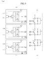
- Figure 3 is a detailed circuit diagram of a switching signal generation part and an inverter according to an embodiment.
- the switching signal generation part 270 may include a gate circuit including photo-couplers 271 P, 272P, and 273P (also optocoupler, opto-isolator) to respectively correspond to the switches so that a switching control signal is applied to each of the plurality of switches S1, S2, and S3 constituting the inverter 220.
- the switching signal generation part 270 may include gate circuit parts 271, 272, and 273 including the photo couplers 271 P, 272P, and 273P, control power applying parts Vcc1, Vcc2, and Vcc3 (also control power/voltage node or terminal), and GND 271 G, 272G, and 273G (also ground node or terminal) to respectively correspond to the switches so that the three switches S1, S2, and S3 of the inverter 220 constituted by a dual half bridge circuit are independently controlled.
- the gate circuit parts 271, 272, and 273 may include a first gate circuit 271, a second gate circuit 272, and a third gate circuit 273 to generate switching signals for controlling the three switches according to an embodiment.
- the first to third gate circuit parts 271 and 273 may include the control power applying parts Vcc1, Vcc2, and Vcc3, and the GND 271 G, 272G, and 273G which are different from each other, respectively.
- Each of the photo couplers 271 P, 272P, and 273P which are respectively provided in the gate circuit parts 271, 272, and 273 may include a light emitting part and a light receiving part and be electrically insulated with respect to each other.
- Each of the photo couplers 271 P, 272P, and 273P may emit light when a control power is applied to a light emitting diode.
- each of the photo couplers 271 P, 272P, and 273P may be in a conduction state.
- the control power is applied to the control power applying parts Vcc1, Vcc2, and Vcc3 respectively corresponding to the photo couplers 271 P, 272P, and 273P
- the photo couplers 271 P, 272P, and 273P may be in the conduction state.
- the switching signal may be applied to the corresponding switches S1, S2, and S3 according to an operation request signal of each of the heating coils applied from the switching signal selection part 280.
- the second gate circuit part 272 may output the control signal to continuously close or open the second switch S2 of the inverter 220 according to the operation request signal of each of the heating coils inputted from the switching signal selection part 280.
- the switching signal generation part 270 may close the first and second switches S1 and S2.
- the first and second gate circuit parts 271 and 272 may be in the conduction state.
- the first resonant circuit 250 may be operated to operate the first heating coil 230.
- the second and third switches S2 and S3 are closed, and the first switch S1 is opened.
- the second and third gate circuit parts 272 and 273 may be in the conduction state.
- the second resonant circuit 260 may be operated to operate the second heating coil 240.
- the first and third switches S1 and S3 are closed, and the second switch S2 is continuously opened.
- the first and third gate circuit parts 271 and 273 may be in the conduction state.
- the first and second resonant circuits 250 and 260 may be operated to operate the first and second heating coils 230 and 240 at the same time.
- the first and third switches S1 and S3 are alternately closed, and the second switch S2 is continuously closed.
- the first and third gate circuit parts 271 and 273 may be in an alternate conduction state
- the second gate circuit part 272 may be in a continuous conduction state.
- the first and second resonant circuits 250 and 260 may be alternately operated to successively and alternately operate the first and second heating coils 230 and 240.
- the switching signal generation part 270 including the gate circuit part including the photo couplers respectively corresponding to the switches to operate the dual half bridge inverter including the three switches was described according to an embodiment. An operation of the induction heat cooking apparatus according to an embodiment will be described by using the above-described components with reference to Figure 4 .
- Figure 4 is a flowchart illustrating an operation of the induction heat cooking apparatus according to an embodiment.
- a switching signal selection part 280 may receive an operation mode selection signal from the outside (S101).
- the switching signal selection part 280 may determine whether an operation mode selection signal inputted from the outside is a first operation mode for operating the first heating coil 230 (S102).
- the switching signal selection part 280 may output a corresponding signal to a switching signal generation part 270.
- the switching signal generation part 270 controls the first to third switches S1 to S3 included in the inverter 220 to close the first and second switches S1 and S2 and open the third switch S3.
- the photo couplers 271 P and 272P of the first and second gate circuit parts 271 and 272 may be in the conduction state to operate only the first coil and the first resonant circuit (S103).
- the switching signal selection part 280 may determine whether an operation request signal of the second heating coil 240 is inputted (S104).
- the switching signal selection part 280 may output a corresponding signal to the switching signal generation part 270.
- the switching signal generation part 270 controls the first to third switches S1 to S3 included in the inverter 220 to close the second and third switches S2 and S3 and open the first switch S1.
- the photo couplers 272P and 273P of the second and third gate circuit parts 272 and 273 may be in the conduction state to operate only the second heating coil and the second resonant circuit (S105).
- the switching signal selection part 280 may determine whether a third operation mode for operating the first and second heating coils 230 and 240 at the same time is selected (S106).
- the switching signal selection part 280 may output a corresponding signal to the switching signal generation part 270.
- the switching signal generation part 270 may control the first to third switches S1 to S3 included in the inverter 220 to close the first and third switch S1 and S3 and open the second switch S2.
- Each of the first and third gate circuit parts 271 may be in the conduction state, and the second gate circuit part 272 may be in an insulation state. Thus, only the first heating coil and the first resonant circuit and the second heating coil and the second resonant circuit may be operated (S107).
- the switching signal selection part 280 may determine whether a fourth operation mode for alternately operating the first and second heating coils 230 and 240 is selected (S108).
- the switching signal selection part 280 may output a corresponding signal to the switching signal generation part 270.
- the switching signal generation part 270 may control the insulation and conduction of the gate circuit so that the corresponding switch and resonant circuit are operated according to an operation order of the first and second heating coils 230 and 240.
- the first and second gate circuit parts 271 and 272 may be controlled in the conduction state to close the first and second switches S1 and S2.
- the third gate circuit 273 may be controlled in the insulation state to open the third switch S3, thereby operating the first heating coil 230.
- the operation of the first heating coil 230 may be finished to operate the second heating coil 240.
- the first gate circuit part 271 of the first and second gate circuit parts 271 and 272 may be converted from the conduction state into the insulation state.
- the third gate circuit part 273 may be converted into the conduction state to close the second and third switches S2 and S3 and open the first switch S1.
- the first and second heating coils may be alternately operated according to the opening and closing of each of the switches depending on the insulation and conduction states of each of the gate circuit parts.
- the induction heat cooking apparatus may be simplified in circuit and reduced in volume to reduce product unit costs.
- the circuit for operating the plurality of heating coils at the same time by using only the one inverter may be provided to improve user satisfaction.
- Embodiments provide an induction heat cooking apparatus including a constitution for generating a gate voltage that operates two resonant circuits by using an inverter including three switches.
- an induction heat cooking apparatus includes: a rectifying part rectifying an input voltage to output a DC voltage; an inverter switching the DC voltage outputted through the rectifying part to generate an AC voltage; a first heating part operated by the AC voltage applied from the inverter; a second heating part connected to the first heating part in parallel, the second heating part being operated by the AC voltage applied from the inverter; and a switching signal generation part controlling an operation state of each of the first and second heating parts from the inverter according to an operation mode inputted from the outside, wherein the switching signal generation part includes a photo coupler.
- any reference in this specification to "one embodiment,” “an embodiment,” “example embodiment,” etc. means that a particular feature, structure, or characteristic described in connection with the embodiment is included in at least one embodiment of the invention.
- the appearances of such phrases in various places in the specification are not necessarily all referring to the same embodiment.
Landscapes
- Physics & Mathematics (AREA)
- Electromagnetism (AREA)
- Induction Heating Cooking Devices (AREA)
- Electric Stoves And Ranges (AREA)
Applications Claiming Priority (1)
| Application Number | Priority Date | Filing Date | Title |
|---|---|---|---|
| KR1020130000084A KR102031907B1 (ko) | 2013-01-02 | 2013-01-02 | 전자 유도 가열 조리기 및 이의 구동 방법 |
Publications (3)
| Publication Number | Publication Date |
|---|---|
| EP2753145A2 true EP2753145A2 (fr) | 2014-07-09 |
| EP2753145A3 EP2753145A3 (fr) | 2014-08-06 |
| EP2753145B1 EP2753145B1 (fr) | 2017-02-08 |
Family
ID=49911347
Family Applications (1)
| Application Number | Title | Priority Date | Filing Date |
|---|---|---|---|
| EP13199745.4A Active EP2753145B1 (fr) | 2013-01-02 | 2013-12-30 | Appareil de cuisson à induction |
Country Status (4)
| Country | Link |
|---|---|
| US (1) | US9554426B2 (fr) |
| EP (1) | EP2753145B1 (fr) |
| KR (1) | KR102031907B1 (fr) |
| ES (1) | ES2623481T3 (fr) |
Cited By (2)
| Publication number | Priority date | Publication date | Assignee | Title |
|---|---|---|---|---|
| CN106900096A (zh) * | 2015-12-18 | 2017-06-27 | E.G.O.电气设备制造股份有限公司 | 加热电路和感应烹饪灶具 |
| EP3570636A4 (fr) * | 2017-01-12 | 2020-08-19 | LG Electronics Inc. -1- | Appareil de cuisson à chauffage par induction |
Families Citing this family (5)
| Publication number | Priority date | Publication date | Assignee | Title |
|---|---|---|---|---|
| KR102306811B1 (ko) * | 2015-06-23 | 2021-09-30 | 엘지전자 주식회사 | 전자 유도 가열 조리기 및 이의 구동 방법 |
| CN107306460B (zh) * | 2016-04-25 | 2020-12-22 | 佛山市顺德区美的电热电器制造有限公司 | 电磁加热系统和用于其的半桥隔离驱动电路 |
| US10993292B2 (en) * | 2017-10-23 | 2021-04-27 | Whirlpool Corporation | System and method for tuning an induction circuit |
| US11309823B2 (en) * | 2020-07-02 | 2022-04-19 | Yefim Tservil | Three phase motor control with variable RPM and variable synchronized PWM |
| JP7657095B2 (ja) | 2021-05-14 | 2025-04-04 | 日立グローバルライフソリューションズ株式会社 | 電磁誘導加熱装置 |
Family Cites Families (14)
| Publication number | Priority date | Publication date | Assignee | Title |
|---|---|---|---|---|
| US4210792A (en) | 1976-07-27 | 1980-07-01 | Tokyo Shibaura Electric Co., Ltd. | Induction heating apparatus with load detecting and control circuit |
| GB2062985B (en) | 1979-11-12 | 1983-11-02 | Matsushita Electric Industrial Co Ltd | Small load detection by comparison between input and output parameters of an induction heat cooking apparatus |
| JP2870945B2 (ja) * | 1990-03-12 | 1999-03-17 | 松下電器産業株式会社 | 誘導加熱調理器 |
| KR940005050B1 (ko) * | 1992-02-11 | 1994-06-10 | 주식회사 금성사 | 고주파 유도가열조리기의 출력보상회로 |
| KR970000539B1 (ko) * | 1993-09-17 | 1997-01-13 | 엘지전자 주식회사 | 인버터 조리기의 고압/저압분리 장치 |
| DE19654269C2 (de) * | 1995-12-27 | 2000-02-17 | Lg Electronics Inc | Induktionskochgerät |
| KR0176904B1 (ko) * | 1996-03-11 | 1999-02-18 | 구자홍 | 듀얼 하프-브릿지형 전자 유도 가열장치 및 제어방법 |
| ES2143430B1 (es) | 1998-09-08 | 2000-12-16 | Balay Sa | Circuito inversor de dos salidas, y circuito y procedimiento de control de la potencia entregada en las salidas del inversor. |
| US6528770B1 (en) * | 1999-04-09 | 2003-03-04 | Jaeger Regulation | Induction cooking hob with induction heaters having power supplied by generators |
| KR20070110997A (ko) | 2006-05-16 | 2007-11-21 | 페어차일드코리아반도체 주식회사 | 스위치 구동장치, 이를 사용하는 하프 브릿지 컨버터 및 그구동방법 |
| JP2010140657A (ja) * | 2008-12-09 | 2010-06-24 | Toshiba Corp | 誘導加熱調理器 |
| EP2528412B1 (fr) | 2010-01-20 | 2015-03-18 | Panasonic Corporation | Appareil de chauffage par induction |
| ES2388028B1 (es) | 2010-03-03 | 2013-08-23 | Bsh Electrodomésticos España, S.A. | Encimera de cocción con al menos una zona de cocción y procedimiento para accionar una encimera de cocción. |
| CN103404229B (zh) | 2011-02-21 | 2015-07-29 | 三菱电机株式会社 | 感应加热烹调器 |
-
2013
- 2013-01-02 KR KR1020130000084A patent/KR102031907B1/ko active Active
- 2013-12-30 ES ES13199745.4T patent/ES2623481T3/es active Active
- 2013-12-30 EP EP13199745.4A patent/EP2753145B1/fr active Active
- 2013-12-31 US US14/145,484 patent/US9554426B2/en active Active
Cited By (5)
| Publication number | Priority date | Publication date | Assignee | Title |
|---|---|---|---|---|
| CN106900096A (zh) * | 2015-12-18 | 2017-06-27 | E.G.O.电气设备制造股份有限公司 | 加热电路和感应烹饪灶具 |
| CN106900096B (zh) * | 2015-12-18 | 2021-05-11 | E.G.O.电气设备制造股份有限公司 | 加热电路和感应烹饪灶具 |
| US11229092B2 (en) | 2015-12-18 | 2022-01-18 | E.G.O. Elektro-Geraetebau Gmbh | Heating circuit and induction cooking hob |
| EP3570636A4 (fr) * | 2017-01-12 | 2020-08-19 | LG Electronics Inc. -1- | Appareil de cuisson à chauffage par induction |
| US11570855B2 (en) | 2017-01-12 | 2023-01-31 | Lg Electronics Inc. | Induction heat cooking apparatus |
Also Published As
| Publication number | Publication date |
|---|---|
| KR102031907B1 (ko) | 2019-10-14 |
| ES2623481T3 (es) | 2017-07-11 |
| US9554426B2 (en) | 2017-01-24 |
| KR20140088323A (ko) | 2014-07-10 |
| EP2753145B1 (fr) | 2017-02-08 |
| US20140183184A1 (en) | 2014-07-03 |
| EP2753145A3 (fr) | 2014-08-06 |
Similar Documents
| Publication | Publication Date | Title |
|---|---|---|
| US9544946B2 (en) | Induction heat cooking apparatus and method for controlling output level thereof | |
| US9572201B2 (en) | Induction heat cooking apparatus and method for controlling output level thereof | |
| EP2753145A2 (fr) | Appareil de cuisson à induction | |
| JP5909675B2 (ja) | 誘導加熱調理器 | |
| KR101659001B1 (ko) | 단일 인버터를 구비한 유도가열 전기조리기 | |
| US20110253706A1 (en) | Heating device with plural induction coils | |
| JP2008289228A (ja) | 電力変換装置 | |
| US20140151365A1 (en) | Electronic induction heating cooker and output level control method thereof | |
| KR20140067328A (ko) | 전자 유도 가열 조리기 및 이의 구동 방법 | |
| KR20090018565A (ko) | 스위칭 모드 전원공급장치 및 그 전원공급방법 | |
| KR20160150512A (ko) | 전자 유도 가열 조리기 | |
| CN103548416B (zh) | 感应加热装置及其运行方法和带感应加热装置的家用器具 | |
| JP2014123539A (ja) | 誘導加熱装置およびそれを用いた炊飯器 | |
| US10517148B2 (en) | Induction heat cooking apparatus and method for driving the same | |
| KR101659000B1 (ko) | 단일 인버터를 구비한 유도가열 전기조리기 | |
| CN103891400A (zh) | 感应加热装置 | |
| JP3937918B2 (ja) | 誘導加熱装置、およびこれを用いた誘導加熱調理器と炊飯器 | |
| US20230217552A1 (en) | Power conversion device, electric range including same, and control method therefor | |
| KR102329539B1 (ko) | 전자 유도 가열 조리기 및 이의 구동 방법 | |
| JP5928005B2 (ja) | スイッチング電源 | |
| KR101757976B1 (ko) | 전자 유도 가열 조리기 및 이의 구동 방법 | |
| KR20160039955A (ko) | 전자 유도 가열 조리기 및 이의 구동 방법 | |
| JP2020053323A (ja) | 誘導加熱調理器 | |
| JP2004192880A (ja) | 誘導加熱装置 |
Legal Events
| Date | Code | Title | Description |
|---|---|---|---|
| PUAL | Search report despatched |
Free format text: ORIGINAL CODE: 0009013 |
|
| 17P | Request for examination filed |
Effective date: 20131230 |
|
| AK | Designated contracting states |
Kind code of ref document: A2 Designated state(s): AL AT BE BG CH CY CZ DE DK EE ES FI FR GB GR HR HU IE IS IT LI LT LU LV MC MK MT NL NO PL PT RO RS SE SI SK SM TR |
|
| AX | Request for extension of the european patent |
Extension state: BA ME |
|
| PUAI | Public reference made under article 153(3) epc to a published international application that has entered the european phase |
Free format text: ORIGINAL CODE: 0009012 |
|
| AK | Designated contracting states |
Kind code of ref document: A3 Designated state(s): AL AT BE BG CH CY CZ DE DK EE ES FI FR GB GR HR HU IE IS IT LI LT LU LV MC MK MT NL NO PL PT RO RS SE SI SK SM TR |
|
| AX | Request for extension of the european patent |
Extension state: BA ME |
|
| RIC1 | Information provided on ipc code assigned before grant |
Ipc: H05B 6/06 20060101ALI20140629BHEP Ipc: H05B 6/02 20060101AFI20140629BHEP |
|
| R17P | Request for examination filed (corrected) |
Effective date: 20150128 |
|
| RBV | Designated contracting states (corrected) |
Designated state(s): AL AT BE BG CH CY CZ DE DK EE ES FI FR GB GR HR HU IE IS IT LI LT LU LV MC MK MT NL NO PL PT RO RS SE SI SK SM TR |
|
| 17Q | First examination report despatched |
Effective date: 20150506 |
|
| GRAP | Despatch of communication of intention to grant a patent |
Free format text: ORIGINAL CODE: EPIDOSNIGR1 |
|
| INTG | Intention to grant announced |
Effective date: 20160722 |
|
| RAP1 | Party data changed (applicant data changed or rights of an application transferred) |
Owner name: LG ELECTRONICS INC. |
|
| GRAS | Grant fee paid |
Free format text: ORIGINAL CODE: EPIDOSNIGR3 |
|
| GRAA | (expected) grant |
Free format text: ORIGINAL CODE: 0009210 |
|
| AK | Designated contracting states |
Kind code of ref document: B1 Designated state(s): AL AT BE BG CH CY CZ DE DK EE ES FI FR GB GR HR HU IE IS IT LI LT LU LV MC MK MT NL NO PL PT RO RS SE SI SK SM TR |
|
| REG | Reference to a national code |
Ref country code: GB Ref legal event code: FG4D |
|
| REG | Reference to a national code |
Ref country code: CH Ref legal event code: EP Ref country code: AT Ref legal event code: REF Ref document number: 867345 Country of ref document: AT Kind code of ref document: T Effective date: 20170215 |
|
| REG | Reference to a national code |
Ref country code: NL Ref legal event code: FP |
|
| REG | Reference to a national code |
Ref country code: IE Ref legal event code: FG4D |
|
| REG | Reference to a national code |
Ref country code: DE Ref legal event code: R096 Ref document number: 602013017288 Country of ref document: DE |
|
| REG | Reference to a national code |
Ref country code: LT Ref legal event code: MG4D |
|
| REG | Reference to a national code |
Ref country code: ES Ref legal event code: FG2A Ref document number: 2623481 Country of ref document: ES Kind code of ref document: T3 Effective date: 20170711 |
|
| REG | Reference to a national code |
Ref country code: AT Ref legal event code: MK05 Ref document number: 867345 Country of ref document: AT Kind code of ref document: T Effective date: 20170208 |
|
| PG25 | Lapsed in a contracting state [announced via postgrant information from national office to epo] |
Ref country code: LT Free format text: LAPSE BECAUSE OF FAILURE TO SUBMIT A TRANSLATION OF THE DESCRIPTION OR TO PAY THE FEE WITHIN THE PRESCRIBED TIME-LIMIT Effective date: 20170208 Ref country code: FI Free format text: LAPSE BECAUSE OF FAILURE TO SUBMIT A TRANSLATION OF THE DESCRIPTION OR TO PAY THE FEE WITHIN THE PRESCRIBED TIME-LIMIT Effective date: 20170208 Ref country code: GR Free format text: LAPSE BECAUSE OF FAILURE TO SUBMIT A TRANSLATION OF THE DESCRIPTION OR TO PAY THE FEE WITHIN THE PRESCRIBED TIME-LIMIT Effective date: 20170509 Ref country code: HR Free format text: LAPSE BECAUSE OF FAILURE TO SUBMIT A TRANSLATION OF THE DESCRIPTION OR TO PAY THE FEE WITHIN THE PRESCRIBED TIME-LIMIT Effective date: 20170208 Ref country code: NO Free format text: LAPSE BECAUSE OF FAILURE TO SUBMIT A TRANSLATION OF THE DESCRIPTION OR TO PAY THE FEE WITHIN THE PRESCRIBED TIME-LIMIT Effective date: 20170508 |
|
| PG25 | Lapsed in a contracting state [announced via postgrant information from national office to epo] |
Ref country code: AT Free format text: LAPSE BECAUSE OF FAILURE TO SUBMIT A TRANSLATION OF THE DESCRIPTION OR TO PAY THE FEE WITHIN THE PRESCRIBED TIME-LIMIT Effective date: 20170208 Ref country code: RS Free format text: LAPSE BECAUSE OF FAILURE TO SUBMIT A TRANSLATION OF THE DESCRIPTION OR TO PAY THE FEE WITHIN THE PRESCRIBED TIME-LIMIT Effective date: 20170208 Ref country code: SE Free format text: LAPSE BECAUSE OF FAILURE TO SUBMIT A TRANSLATION OF THE DESCRIPTION OR TO PAY THE FEE WITHIN THE PRESCRIBED TIME-LIMIT Effective date: 20170208 Ref country code: PT Free format text: LAPSE BECAUSE OF FAILURE TO SUBMIT A TRANSLATION OF THE DESCRIPTION OR TO PAY THE FEE WITHIN THE PRESCRIBED TIME-LIMIT Effective date: 20170608 Ref country code: LV Free format text: LAPSE BECAUSE OF FAILURE TO SUBMIT A TRANSLATION OF THE DESCRIPTION OR TO PAY THE FEE WITHIN THE PRESCRIBED TIME-LIMIT Effective date: 20170208 Ref country code: BG Free format text: LAPSE BECAUSE OF FAILURE TO SUBMIT A TRANSLATION OF THE DESCRIPTION OR TO PAY THE FEE WITHIN THE PRESCRIBED TIME-LIMIT Effective date: 20170508 |
|
| PG25 | Lapsed in a contracting state [announced via postgrant information from national office to epo] |
Ref country code: EE Free format text: LAPSE BECAUSE OF FAILURE TO SUBMIT A TRANSLATION OF THE DESCRIPTION OR TO PAY THE FEE WITHIN THE PRESCRIBED TIME-LIMIT Effective date: 20170208 Ref country code: SK Free format text: LAPSE BECAUSE OF FAILURE TO SUBMIT A TRANSLATION OF THE DESCRIPTION OR TO PAY THE FEE WITHIN THE PRESCRIBED TIME-LIMIT Effective date: 20170208 Ref country code: RO Free format text: LAPSE BECAUSE OF FAILURE TO SUBMIT A TRANSLATION OF THE DESCRIPTION OR TO PAY THE FEE WITHIN THE PRESCRIBED TIME-LIMIT Effective date: 20170208 Ref country code: CZ Free format text: LAPSE BECAUSE OF FAILURE TO SUBMIT A TRANSLATION OF THE DESCRIPTION OR TO PAY THE FEE WITHIN THE PRESCRIBED TIME-LIMIT Effective date: 20170208 |
|
| REG | Reference to a national code |
Ref country code: DE Ref legal event code: R097 Ref document number: 602013017288 Country of ref document: DE |
|
| REG | Reference to a national code |
Ref country code: FR Ref legal event code: PLFP Year of fee payment: 5 |
|
| PG25 | Lapsed in a contracting state [announced via postgrant information from national office to epo] |
Ref country code: SM Free format text: LAPSE BECAUSE OF FAILURE TO SUBMIT A TRANSLATION OF THE DESCRIPTION OR TO PAY THE FEE WITHIN THE PRESCRIBED TIME-LIMIT Effective date: 20170208 Ref country code: PL Free format text: LAPSE BECAUSE OF FAILURE TO SUBMIT A TRANSLATION OF THE DESCRIPTION OR TO PAY THE FEE WITHIN THE PRESCRIBED TIME-LIMIT Effective date: 20170208 Ref country code: DK Free format text: LAPSE BECAUSE OF FAILURE TO SUBMIT A TRANSLATION OF THE DESCRIPTION OR TO PAY THE FEE WITHIN THE PRESCRIBED TIME-LIMIT Effective date: 20170208 |
|
| PLBE | No opposition filed within time limit |
Free format text: ORIGINAL CODE: 0009261 |
|
| STAA | Information on the status of an ep patent application or granted ep patent |
Free format text: STATUS: NO OPPOSITION FILED WITHIN TIME LIMIT |
|
| 26N | No opposition filed |
Effective date: 20171109 |
|
| PG25 | Lapsed in a contracting state [announced via postgrant information from national office to epo] |
Ref country code: SI Free format text: LAPSE BECAUSE OF FAILURE TO SUBMIT A TRANSLATION OF THE DESCRIPTION OR TO PAY THE FEE WITHIN THE PRESCRIBED TIME-LIMIT Effective date: 20170208 |
|
| REG | Reference to a national code |
Ref country code: CH Ref legal event code: PL |
|
| PG25 | Lapsed in a contracting state [announced via postgrant information from national office to epo] |
Ref country code: MT Free format text: LAPSE BECAUSE OF NON-PAYMENT OF DUE FEES Effective date: 20171230 Ref country code: LU Free format text: LAPSE BECAUSE OF NON-PAYMENT OF DUE FEES Effective date: 20171230 |
|
| REG | Reference to a national code |
Ref country code: IE Ref legal event code: MM4A |
|
| REG | Reference to a national code |
Ref country code: BE Ref legal event code: MM Effective date: 20171231 |
|
| PG25 | Lapsed in a contracting state [announced via postgrant information from national office to epo] |
Ref country code: IE Free format text: LAPSE BECAUSE OF NON-PAYMENT OF DUE FEES Effective date: 20171230 |
|
| REG | Reference to a national code |
Ref country code: FR Ref legal event code: PLFP Year of fee payment: 6 |
|
| PG25 | Lapsed in a contracting state [announced via postgrant information from national office to epo] |
Ref country code: BE Free format text: LAPSE BECAUSE OF NON-PAYMENT OF DUE FEES Effective date: 20171231 Ref country code: CH Free format text: LAPSE BECAUSE OF NON-PAYMENT OF DUE FEES Effective date: 20171231 Ref country code: LI Free format text: LAPSE BECAUSE OF NON-PAYMENT OF DUE FEES Effective date: 20171231 |
|
| PG25 | Lapsed in a contracting state [announced via postgrant information from national office to epo] |
Ref country code: HU Free format text: LAPSE BECAUSE OF FAILURE TO SUBMIT A TRANSLATION OF THE DESCRIPTION OR TO PAY THE FEE WITHIN THE PRESCRIBED TIME-LIMIT; INVALID AB INITIO Effective date: 20131230 Ref country code: MC Free format text: LAPSE BECAUSE OF FAILURE TO SUBMIT A TRANSLATION OF THE DESCRIPTION OR TO PAY THE FEE WITHIN THE PRESCRIBED TIME-LIMIT Effective date: 20170208 |
|
| PG25 | Lapsed in a contracting state [announced via postgrant information from national office to epo] |
Ref country code: CY Free format text: LAPSE BECAUSE OF NON-PAYMENT OF DUE FEES Effective date: 20170208 |
|
| PG25 | Lapsed in a contracting state [announced via postgrant information from national office to epo] |
Ref country code: MK Free format text: LAPSE BECAUSE OF FAILURE TO SUBMIT A TRANSLATION OF THE DESCRIPTION OR TO PAY THE FEE WITHIN THE PRESCRIBED TIME-LIMIT Effective date: 20170208 |
|
| PG25 | Lapsed in a contracting state [announced via postgrant information from national office to epo] |
Ref country code: TR Free format text: LAPSE BECAUSE OF FAILURE TO SUBMIT A TRANSLATION OF THE DESCRIPTION OR TO PAY THE FEE WITHIN THE PRESCRIBED TIME-LIMIT Effective date: 20170208 |
|
| PG25 | Lapsed in a contracting state [announced via postgrant information from national office to epo] |
Ref country code: AL Free format text: LAPSE BECAUSE OF FAILURE TO SUBMIT A TRANSLATION OF THE DESCRIPTION OR TO PAY THE FEE WITHIN THE PRESCRIBED TIME-LIMIT Effective date: 20170208 Ref country code: IS Free format text: LAPSE BECAUSE OF FAILURE TO SUBMIT A TRANSLATION OF THE DESCRIPTION OR TO PAY THE FEE WITHIN THE PRESCRIBED TIME-LIMIT Effective date: 20170608 |
|
| P01 | Opt-out of the competence of the unified patent court (upc) registered |
Effective date: 20230524 |
|
| PGFP | Annual fee paid to national office [announced via postgrant information from national office to epo] |
Ref country code: NL Payment date: 20241106 Year of fee payment: 12 |
|
| PGFP | Annual fee paid to national office [announced via postgrant information from national office to epo] |
Ref country code: GB Payment date: 20241105 Year of fee payment: 12 |
|
| PGFP | Annual fee paid to national office [announced via postgrant information from national office to epo] |
Ref country code: FR Payment date: 20241112 Year of fee payment: 12 |
|
| PGFP | Annual fee paid to national office [announced via postgrant information from national office to epo] |
Ref country code: IT Payment date: 20241107 Year of fee payment: 12 |
|
| PGFP | Annual fee paid to national office [announced via postgrant information from national office to epo] |
Ref country code: ES Payment date: 20250113 Year of fee payment: 12 |
|
| PGFP | Annual fee paid to national office [announced via postgrant information from national office to epo] |
Ref country code: DE Payment date: 20251105 Year of fee payment: 13 |