EP2754100B1 - Dispositif rfid à structure allongée - Google Patents
Dispositif rfid à structure allongée Download PDFInfo
- Publication number
- EP2754100B1 EP2754100B1 EP12773429.1A EP12773429A EP2754100B1 EP 2754100 B1 EP2754100 B1 EP 2754100B1 EP 12773429 A EP12773429 A EP 12773429A EP 2754100 B1 EP2754100 B1 EP 2754100B1
- Authority
- EP
- European Patent Office
- Prior art keywords
- conductive portion
- label
- rfid
- antenna
- jewelry
- Prior art date
- Legal status (The legal status is an assumption and is not a legal conclusion. Google has not performed a legal analysis and makes no representation as to the accuracy of the status listed.)
- Active
Links
Images



Classifications
-
- G—PHYSICS
- G06—COMPUTING OR CALCULATING; COUNTING
- G06K—GRAPHICAL DATA READING; PRESENTATION OF DATA; RECORD CARRIERS; HANDLING RECORD CARRIERS
- G06K19/00—Record carriers for use with machines and with at least a part designed to carry digital markings
- G06K19/06—Record carriers for use with machines and with at least a part designed to carry digital markings characterised by the kind of the digital marking, e.g. shape, nature, code
- G06K19/067—Record carriers with conductive marks, printed circuits or semiconductor circuit elements, e.g. credit or identity cards also with resonating or responding marks without active components
- G06K19/07—Record carriers with conductive marks, printed circuits or semiconductor circuit elements, e.g. credit or identity cards also with resonating or responding marks without active components with integrated circuit chips
- G06K19/077—Constructional details, e.g. mounting of circuits in the carrier
- G06K19/07749—Constructional details, e.g. mounting of circuits in the carrier the record carrier being capable of non-contact communication, e.g. constructional details of the antenna of a non-contact smart card
- G06K19/07773—Antenna details
-
- G—PHYSICS
- G08—SIGNALLING
- G08B—SIGNALLING SYSTEMS, e.g. PERSONAL CALLING SYSTEMS; ORDER TELEGRAPHS; ALARM SYSTEMS
- G08B13/00—Burglar, theft or intruder alarms
- G08B13/22—Electrical actuation
- G08B13/24—Electrical actuation by interference with electromagnetic field distribution
- G08B13/2402—Electronic Article Surveillance [EAS], i.e. systems using tags for detecting removal of a tagged item from a secure area, e.g. tags for detecting shoplifting
- G08B13/2405—Electronic Article Surveillance [EAS], i.e. systems using tags for detecting removal of a tagged item from a secure area, e.g. tags for detecting shoplifting characterised by the tag technology used
- G08B13/2414—Electronic Article Surveillance [EAS], i.e. systems using tags for detecting removal of a tagged item from a secure area, e.g. tags for detecting shoplifting characterised by the tag technology used using inductive tags
- G08B13/2417—Electronic Article Surveillance [EAS], i.e. systems using tags for detecting removal of a tagged item from a secure area, e.g. tags for detecting shoplifting characterised by the tag technology used using inductive tags having a radio frequency identification chip
-
- G—PHYSICS
- G06—COMPUTING OR CALCULATING; COUNTING
- G06K—GRAPHICAL DATA READING; PRESENTATION OF DATA; RECORD CARRIERS; HANDLING RECORD CARRIERS
- G06K19/00—Record carriers for use with machines and with at least a part designed to carry digital markings
- G06K19/06—Record carriers for use with machines and with at least a part designed to carry digital markings characterised by the kind of the digital marking, e.g. shape, nature, code
- G06K19/067—Record carriers with conductive marks, printed circuits or semiconductor circuit elements, e.g. credit or identity cards also with resonating or responding marks without active components
- G06K19/07—Record carriers with conductive marks, printed circuits or semiconductor circuit elements, e.g. credit or identity cards also with resonating or responding marks without active components with integrated circuit chips
- G06K19/077—Constructional details, e.g. mounting of circuits in the carrier
- G06K19/07749—Constructional details, e.g. mounting of circuits in the carrier the record carrier being capable of non-contact communication, e.g. constructional details of the antenna of a non-contact smart card
- G06K19/07758—Constructional details, e.g. mounting of circuits in the carrier the record carrier being capable of non-contact communication, e.g. constructional details of the antenna of a non-contact smart card arrangements for adhering the record carrier to further objects or living beings, functioning as an identification tag
-
- G—PHYSICS
- G06—COMPUTING OR CALCULATING; COUNTING
- G06K—GRAPHICAL DATA READING; PRESENTATION OF DATA; RECORD CARRIERS; HANDLING RECORD CARRIERS
- G06K19/00—Record carriers for use with machines and with at least a part designed to carry digital markings
- G06K19/06—Record carriers for use with machines and with at least a part designed to carry digital markings characterised by the kind of the digital marking, e.g. shape, nature, code
- G06K19/067—Record carriers with conductive marks, printed circuits or semiconductor circuit elements, e.g. credit or identity cards also with resonating or responding marks without active components
- G06K19/07—Record carriers with conductive marks, printed circuits or semiconductor circuit elements, e.g. credit or identity cards also with resonating or responding marks without active components with integrated circuit chips
- G06K19/077—Constructional details, e.g. mounting of circuits in the carrier
- G06K19/07749—Constructional details, e.g. mounting of circuits in the carrier the record carrier being capable of non-contact communication, e.g. constructional details of the antenna of a non-contact smart card
- G06K19/07771—Constructional details, e.g. mounting of circuits in the carrier the record carrier being capable of non-contact communication, e.g. constructional details of the antenna of a non-contact smart card the record carrier comprising means for minimising adverse effects on the data communication capability of the record carrier, e.g. minimising Eddy currents induced in a proximate metal or otherwise electromagnetically interfering object
-
- G—PHYSICS
- G06—COMPUTING OR CALCULATING; COUNTING
- G06K—GRAPHICAL DATA READING; PRESENTATION OF DATA; RECORD CARRIERS; HANDLING RECORD CARRIERS
- G06K19/00—Record carriers for use with machines and with at least a part designed to carry digital markings
- G06K19/06—Record carriers for use with machines and with at least a part designed to carry digital markings characterised by the kind of the digital marking, e.g. shape, nature, code
- G06K19/067—Record carriers with conductive marks, printed circuits or semiconductor circuit elements, e.g. credit or identity cards also with resonating or responding marks without active components
- G06K19/07—Record carriers with conductive marks, printed circuits or semiconductor circuit elements, e.g. credit or identity cards also with resonating or responding marks without active components with integrated circuit chips
- G06K19/077—Constructional details, e.g. mounting of circuits in the carrier
- G06K19/07749—Constructional details, e.g. mounting of circuits in the carrier the record carrier being capable of non-contact communication, e.g. constructional details of the antenna of a non-contact smart card
- G06K19/07773—Antenna details
- G06K19/07786—Antenna details the antenna being of the HF type, such as a dipole
-
- G—PHYSICS
- G06—COMPUTING OR CALCULATING; COUNTING
- G06K—GRAPHICAL DATA READING; PRESENTATION OF DATA; RECORD CARRIERS; HANDLING RECORD CARRIERS
- G06K19/00—Record carriers for use with machines and with at least a part designed to carry digital markings
- G06K19/06—Record carriers for use with machines and with at least a part designed to carry digital markings characterised by the kind of the digital marking, e.g. shape, nature, code
- G06K19/067—Record carriers with conductive marks, printed circuits or semiconductor circuit elements, e.g. credit or identity cards also with resonating or responding marks without active components
- G06K19/07—Record carriers with conductive marks, printed circuits or semiconductor circuit elements, e.g. credit or identity cards also with resonating or responding marks without active components with integrated circuit chips
- G06K19/077—Constructional details, e.g. mounting of circuits in the carrier
- G06K19/07749—Constructional details, e.g. mounting of circuits in the carrier the record carrier being capable of non-contact communication, e.g. constructional details of the antenna of a non-contact smart card
- G06K19/07773—Antenna details
- G06K19/0779—Antenna details the antenna being foldable or folded
-
- G—PHYSICS
- G06—COMPUTING OR CALCULATING; COUNTING
- G06K—GRAPHICAL DATA READING; PRESENTATION OF DATA; RECORD CARRIERS; HANDLING RECORD CARRIERS
- G06K19/00—Record carriers for use with machines and with at least a part designed to carry digital markings
- G06K19/06—Record carriers for use with machines and with at least a part designed to carry digital markings characterised by the kind of the digital marking, e.g. shape, nature, code
- G06K19/067—Record carriers with conductive marks, printed circuits or semiconductor circuit elements, e.g. credit or identity cards also with resonating or responding marks without active components
- G06K19/07—Record carriers with conductive marks, printed circuits or semiconductor circuit elements, e.g. credit or identity cards also with resonating or responding marks without active components with integrated circuit chips
- G06K19/077—Constructional details, e.g. mounting of circuits in the carrier
- G06K19/07749—Constructional details, e.g. mounting of circuits in the carrier the record carrier being capable of non-contact communication, e.g. constructional details of the antenna of a non-contact smart card
- G06K19/07798—Constructional details, e.g. mounting of circuits in the carrier the record carrier being capable of non-contact communication, e.g. constructional details of the antenna of a non-contact smart card part of the antenna or the integrated circuit being adapted for rupturing or breaking, e.g. record carriers functioning as sealing devices for detecting not-authenticated opening of containers
-
- G—PHYSICS
- G08—SIGNALLING
- G08B—SIGNALLING SYSTEMS, e.g. PERSONAL CALLING SYSTEMS; ORDER TELEGRAPHS; ALARM SYSTEMS
- G08B13/00—Burglar, theft or intruder alarms
- G08B13/22—Electrical actuation
- G08B13/24—Electrical actuation by interference with electromagnetic field distribution
- G08B13/2402—Electronic Article Surveillance [EAS], i.e. systems using tags for detecting removal of a tagged item from a secure area, e.g. tags for detecting shoplifting
- G08B13/2428—Tag details
- G08B13/2434—Tag housing and attachment details
-
- H—ELECTRICITY
- H01—ELECTRIC ELEMENTS
- H01Q—ANTENNAS, i.e. RADIO AERIALS
- H01Q1/00—Details of, or arrangements associated with, antennas
- H01Q1/12—Supports; Mounting means
- H01Q1/22—Supports; Mounting means by structural association with other equipment or articles
- H01Q1/2208—Supports; Mounting means by structural association with other equipment or articles associated with components used in interrogation type services, i.e. in systems for information exchange between an interrogator/reader and a tag/transponder, e.g. in Radio Frequency Identification [RFID] systems
- H01Q1/2225—Supports; Mounting means by structural association with other equipment or articles associated with components used in interrogation type services, i.e. in systems for information exchange between an interrogator/reader and a tag/transponder, e.g. in Radio Frequency Identification [RFID] systems used in active tags, i.e. provided with its own power source or in passive tags, i.e. deriving power from RF signal
-
- H—ELECTRICITY
- H01—ELECTRIC ELEMENTS
- H01Q—ANTENNAS, i.e. RADIO AERIALS
- H01Q9/00—Electrically-short antennas having dimensions not more than twice the operating wavelength and consisting of conductive active radiating elements
- H01Q9/04—Resonant antennas
- H01Q9/16—Resonant antennas with feed intermediate between the extremities of the antenna, e.g. centre-fed dipole
- H01Q9/26—Resonant antennas with feed intermediate between the extremities of the antenna, e.g. centre-fed dipole with folded element or elements, the folded parts being spaced apart a small fraction of operating wavelength
Definitions
- the present invention is in the field of radio frequency identification (“RFID”) devices and more particularly to RFID devices used in connection with consumer goods which may have an adverse impact on the performance of the RFID device.
- RFID radio frequency identification
- RFID tags can be used to allow a fast inventory of items in a retail environment, for example jewelry placed in a display case. It is important that such a RFID tag is placed onto the item in a way that is both secure and unobtrusive.
- a pricing label is applied to the article with a thin extension or tab that wraps around some portion of the jewelry item to identify the piece to the customer and to provide an indication as to the price for the retailer.
- the tag In order to obtain maximum performance from a RFID tag it is desirable that the tag is as large as possible. In particular, it is believed that increasing the length, increasing the dimension towards that of a half wave dipole, will help increase antenna gain and efficiency. However, creating such a RFID device can be expensive.
- RFID devices that have small antennas, such as those that can be inserted into a label suitable for attaching to a broad variety of jewelry items, tend to have a relatively narrow operating frequency bandwidth and as such are not as desirable as other options.
- Another problem associated with labeling consumer items such as jewelry is for a part of the antenna to be placed into the tab that is connected or attached to the jewelry item.
- the antenna comes into contact or proximity of the conductive material of the jewelry or other consumer item causing the RFID device to couple to the metal of jewelry item which will then alter the operating frequency of the antenna and potentially reduce the performance.
- Document US 2004/0066296 A1 discloses a tamper indicating label including RFID components and a tamper track coupled to the RFID components, wherein the tamper track forms a tail.
- Document WO 2006/053692 A1 discloses an RFID device attachable to an object comprising a first and a second circuit elements such that the RFID device is able to interact with a remote reading device only when two elements are folded on each other.
- Document US 2007/0125867 A1 discloses a tamper evident RFID circuit comprising a fold section that forms a capacitive element when folded together.
- a jewelry electronic label is provided with a base board, on which an antenna and a chip are arranged; the base board is made of a soft medium material with the thickness of less than 1 mm; and the antenna is formed by a rectangular short circuit ring and a single oscillator unit.
- This invention relates to electrically small RFID tags designed to be attached to metallic objects such as jewelry, where, to increase performance, the RFID tag antenna is extended into the tab.
- This tab causes the RFID tag to interact strongly with the metallic object and can cause it to deviate from the wanted frequency substantially if a simple single conductive line tab extension is used.
- modified forms of antenna extensions designed to go into the tab section are proposed. These antenna forms compensate more than a simple antenna structures when the tab is wrapped around a metallic object, thereby reducing the effective length of the antenna.
- FIGURE 1 An antenna structure is shown in FIGURE 1 .
- an elongated label structure incorporating the antenna structure is folded back upon itself as shown in FIGURE 5 the reduction in length is directly proportional to the degree of folding.
- a RFID antenna structure for use with a RFID tag includes a conductive material that has first and second portions with the first portion having a first antenna pattern and the second portion having a second antenna pattern distinct from the first antenna pattern.
- the second antenna portion cooperates with a conductive surface and the second portion is folded on itself and attached to a part of the conductive surface such that the second portion does not significantly modify performance of the first portion.
- a RFID device in another exemplary embodiment, includes the antenna structure described above, a chip and a label structure.
- the antenna structure is applied to the surface of the label structure.
- a RFID device is provided with a label to enable connection of the RFID device to a consumer item such as jewelry.
- the resulting structure does not result in decreased performance.
- tag is intended to include labels, tags, inlays and the like which are commonly used in connection with creating RFID devices.
- the graph below shows the sensitivity frequency response of the tag design with the simple tab; on a relatively small object, such as a gold ring, the frequency deviation is small. However, on a larger linear object, such as a bracelet, there is significant frequency deviation.
- the extension of the antenna structure into the tab section of the label is in the form of a paddle shape, a large head with a smaller handle portion, as illustrated in FIGURE 2 .
- the antenna structure In its un-mounted state the antenna structure is extended by the length of the line forming the handle of the paddle or the elongated portion extending away from the antenna tab section and the design is made to respond at the desired frequency in this state.
- the proximity effect of the metal reduces the effective antenna length by an amount greater than the change in effective length that compensates to some degree for the length extension caused by the antenna field coupling into the metal object, stabilizing the operating frequency.
- FIGURE 1 shows the antenna design generally designated by reference numeral 10.
- the antenna design 10 includes a first section 12 and a second section 14 which is an elongated portion extending generally way from the first section or portion 12.
- the first portion 12 is shown as a dipole antenna and includes generally a pattern that is formed from a conductive material such as aluminum and has first and second parts 11 and 13.
- the first and second portions, 12 and 14, are distinct from one another and the first section 12 can have first and second parts to form the antenna structure 10.
- FIGURE 2 shows the antenna structure 10 applied to a surface of a substrate such as a label structure 16.
- the substrate can include any type of material such as card stock, pressure sensitive label material, films, papers, foam, woven and non-woven materials and the like.
- the substrate or label structure 16 has both longitudinal 19 and 19'and transverse edges 17 and 17'.
- the label structure 16, in one exemplary embodiment has a fold line 18 which runs about half way through the length of the structure 16 and forms first and second sections 21 and 23 and allows the label structure 16 to be folded on itself to cover the first portion 12 of the antenna. It should be understood that the substrate or label structure may have any particular dimensions and the fold line may be disposed at any appropriate location on the substrate depending on the particular design of the tag, label or inlay.
- the label structure 16 also includes an extended portion 20 on which the second portion 14 is placed.
- the extended portion can extend from at least one transverse 17, 17' or longitudinal edges 19, 19' of the label structure.
- the present invention contemplates that in one embodiment the label structure 16 may serve as the conductive portion that formed the antenna structure of the present invention.
- the extended portion 20 is generally longer and wider than the second portion 14 of the antenna structure 10 but is not required to be and may instead have equal or substantially equal dimensions to that of the second portion 14.
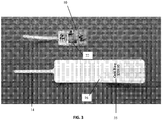
- FIGURE 2 also shows a chip 22 attached to the antenna to form a RFID device. The chip may either be attached directly to the antenna or may be attached via the use of a strap which is what is depicted in FIGURE 3 or other connection.
- FIGURE 3 provides a representative view of the antenna structure 10 attached to a strap/chip 22 adjacent the label structure 16 to show the approximate size of each.
- the label structure is approximately two times the size of the antenna structure so as to allow the antenna structure to be concealed by the label structure when it is folded over on itself.
- the label structure or substrate can be of any particular size or configuration which may be used to cover or conceal the RFID device.
- the substrate may also be provided with printed indicia 35 which may include variable or fixed printing such as pricing or product information.
- the RFID antenna structure 10 shown in the FIGURES may be provided as part of a RFID inlay, label or tag which is available from Avery Dennison RFID Company of Clinton, SC.
- the present invention contemplates that the antenna structure 10 of the present invention is a dipole antenna.
- FIGURE 4 provides a further illustration of the antenna structure 10 with an RFID chip 22 applied to the label structure 16, creating an RFID device.
- FIGURE 5 provides an illustration of the label structure 16 folded over the antenna structure and chip 22 fully concealing the first portion of the antenna (not shown) but allowing the second portion 14 of the antenna structure to still be exposed on the elongated portion 20 of the label structure 16.
- FIGURE 6 shows an exemplary use of the presently described invention, in which a piece of jewelry, such as a gold ring 30 is provided in a retail display box 32.
- the label structure 34 which conceals the first portion of the antenna structure is attached to the ring 30 by the elongated section 36 of the label structure 34 by wrapping the elongated section onto itself and through the opening in the ring. While the antenna would couple to the conductive material the elongated section of the antenna by wrapping onto itself effectively retunes the antenna so that performance of the antenna is not materially altered as shown in the graph above.
- Indicia 35 may be provided on the label or substrate for identification purposes.
- the present invention contemplates that in one embodiment the RFID tag of the present invention has more than one extending portion 20 of the label structure 16.
- the multiple elongated portions may be used to join a plurality of articles such as earrings.
- the present invention contemplates that in a further embodiment more than one antenna structure 10 may be applied to a label structure 16 of the present invention.
- An additional RFID chip 22 may also be applied.
- the chip may be applied directly to the antenna or as part of a strap based configuration.
- the present invention further contemplates that the tag of the present invention may serve a dual purpose. Specifically, the tag of the present invention may serve both a RFID function and EAS function.
- the RFID tag functions at an ultra high frequency (UHF) range, a high frequency range (HF) or low frequency range (LF).
- UHF ultra high frequency
- HF high frequency range
- LF low frequency range
Landscapes
- Engineering & Computer Science (AREA)
- Physics & Mathematics (AREA)
- General Physics & Mathematics (AREA)
- Microelectronics & Electronic Packaging (AREA)
- Computer Hardware Design (AREA)
- Theoretical Computer Science (AREA)
- Electromagnetism (AREA)
- Computer Networks & Wireless Communication (AREA)
- Automation & Control Theory (AREA)
- Computer Security & Cryptography (AREA)
- Details Of Aerials (AREA)
Claims (13)
- Une structure (10) étant adaptée de sorte à pouvoir être utilisée en tant qu'antenne dans un dispositif RFID, la structure (10) consistant en un matériau conducteur et la structure (10) comportant :une première partie conductrice (12) et une deuxième partie conductrice (14) reliée de façon conductrice à la première partie conductrice (12),la première partie conductrice (12) étant une antenne dipôle qui inclut un motif qui a une première (11) et une deuxième (13) partie et la deuxième partie conductrice (14) étant une partie allongée s'étendant en éloignement de la première partie conductrice (12) ;dans laquelle la structure (10) est adaptée de sorte à pouvoir être rattachée à une pièce métallique de joaillerie (30) en ce que la deuxième partie conductrice (14) est enveloppée à travers une ouverture dans la pièce de joaillerie (30) de sorte à chevaucher la première partie conductrice (12), réduisant ainsi la longueur effective et en compensant les effets de couplage avec la pièce de joaillerie (30) au niveau de la performance de la structure (10) utilisée en tant qu'antenne, la structure (10) étant construite comme le montre la Figure 1.
- Un système comportant :une structure (10) selon la revendication 1 ;une puce RFID (22) attachée à ladite structure (10), la structure (10) et la puce RFID (22) formant ainsi un dispositif RFID ;un substrat d'étiquette (16), dans lequel le dispositif RFID a été fourni sur une surface du substrat d'étiquette (16), formant ainsi une étiquette RFID (34) et le substrat d'étiquette (16) a été plié de sorte à recouvrir la première partie conductrice (12) tel que défini à la revendication 1 ;au moins une pièce de joaillerie comportant du métal (30) ;dans lequel l'étiquette RFID (34) a été attachée à au moins une pièce de joaillerie en ce que la deuxième partie conductrice (14) de la structure (10) selon la revendication 1 a été enveloppée à travers une ouverture dans la pièce de joaillerie de sorte à chevaucher la première partie conductrice (12).
- La structure (10) selon la revendication 1, dans laquelle la structure (10) est une feuille d'aluminium à motifs.
- Le système selon la revendication 2, dans lequel l'étiquette RFID (34) présente une multitude de parties rallongées.
- Le système selon la revendication 2, dans lequel le substrat d'étiquette (16) présente une ligne de pli qui passe environ à mi-chemin de la longueur de la structure et permet que le substrat d'étiquette soit replié sur lui-même afin de recouvrir la première partie conductrice (14).
- Le système selon la revendication 2, dans lequel le substrat d'étiquette (16) inclut au moins un partie rallongée (20).
- Le système selon la revendication 6, dans lequel la deuxième partie conductrice (14) de la structure (10) est placée sur la partie rallongée (20).
- Le système selon la revendication 2, dans lequel le substrat d'étiquette (16) a une taille environ deux fois supérieure à celle de la structure (10).
- Le système selon la revendication 2, dans lequel plus qu'une structure (10) selon la revendication 1 est appliquée sur au moins une puce (22) et le substrat d'étiquette (16).
- Le système selon la revendication 2, dans lequel le dispositif RFID présente une fonction EAS.
- Le système selon la revendication 2, dans lequel le dispositif RFID fonctionne sur une plage de fréquences parmi des plages de fréquences très hautes, hautes et basses.
- Le système selon la revendication 6, dans lequel la au moins une partie rallongée (20) s'étend à partir d'au moins un bord longitudinal (19, 19') du substrat d'étiquette (16).
- Le système selon la revendication 6, dans lequel au moins une partie rallongée (20) s'étend à partir d'au moins un bord transversal (17, 17') du substrat d'étiquette (16).
Applications Claiming Priority (2)
| Application Number | Priority Date | Filing Date | Title |
|---|---|---|---|
| US201161532524P | 2011-09-08 | 2011-09-08 | |
| PCT/US2012/054095 WO2013036725A1 (fr) | 2011-09-08 | 2012-09-07 | Dispositif rfid à structure allongée |
Publications (2)
| Publication Number | Publication Date |
|---|---|
| EP2754100A1 EP2754100A1 (fr) | 2014-07-16 |
| EP2754100B1 true EP2754100B1 (fr) | 2017-08-09 |
Family
ID=47040782
Family Applications (1)
| Application Number | Title | Priority Date | Filing Date |
|---|---|---|---|
| EP12773429.1A Active EP2754100B1 (fr) | 2011-09-08 | 2012-09-07 | Dispositif rfid à structure allongée |
Country Status (4)
| Country | Link |
|---|---|
| US (1) | US9767405B2 (fr) |
| EP (1) | EP2754100B1 (fr) |
| CN (1) | CN103917991B (fr) |
| WO (1) | WO2013036725A1 (fr) |
Families Citing this family (22)
| Publication number | Priority date | Publication date | Assignee | Title |
|---|---|---|---|---|
| FR3010816B1 (fr) * | 2013-09-18 | 2017-01-13 | Tagsys | Dispositif de radio-identification d'un objet |
| CN104979618B (zh) * | 2015-06-11 | 2016-05-18 | 湖北伟能达印刷包装有限公司 | Rfid标签 |
| CN104979619A (zh) * | 2015-06-11 | 2015-10-14 | 江健良 | 设有增频缺口的rfid标签 |
| CN104866894A (zh) * | 2015-06-11 | 2015-08-26 | 江健良 | 设有隔离槽的耦合电容rfid标签 |
| CN104993223B (zh) * | 2015-06-11 | 2016-05-11 | 朱洪杨 | Rfid标签天线 |
| CN104916906A (zh) * | 2015-06-11 | 2015-09-16 | 江健良 | 插合耦合电容rfid标签天线 |
| WO2018045550A1 (fr) * | 2016-09-09 | 2018-03-15 | Hong Kong R&D Centre for Logistics and Supply Chain Management Enabling Technologies Limited | Dispositif de communication radiofréquence et son procédé d'utilisation |
| US10320054B2 (en) * | 2016-10-28 | 2019-06-11 | Avery Dennison Retail Information Services, Llc | RFID tags designed to work on difficult substrates |
| CN110100254B (zh) | 2016-12-29 | 2023-10-27 | 艾利丹尼森零售信息服务公司 | 用于谐振元件和超高频天线的双功能条带 |
| CN108038534B (zh) * | 2018-01-30 | 2024-04-05 | 成都德杉科技有限公司 | 一种rfid珠宝标签 |
| WO2019224575A1 (fr) | 2018-05-22 | 2019-11-28 | Tyco Fire & Security Gmbh | Étiquette souple allongée |
| CA3101005A1 (fr) | 2018-06-01 | 2019-12-05 | Stress Engineering Services, Inc. | Systemes et procedes de logistique de surveillance, de suivi et de retracage |
| JP2022509069A (ja) * | 2018-11-16 | 2022-01-20 | エイヴェリー デニソン リテール インフォメーション サービシズ リミテッド ライアビリティ カンパニー | Rfidラベルの形成及び配置のための方法、システム並びに装置 |
| US12223814B2 (en) | 2019-09-16 | 2025-02-11 | Sensormatic Electronics, LLC | Security tag for textiles using conductive thread |
| US10970613B1 (en) | 2019-09-18 | 2021-04-06 | Sensormatic Electronics, LLC | Systems and methods for providing tags adapted to be incorporated with or in items |
| US11443160B2 (en) | 2019-09-18 | 2022-09-13 | Sensormatic Electronics, LLC | Systems and methods for laser tuning and attaching RFID tags to products |
| US11055588B2 (en) | 2019-11-27 | 2021-07-06 | Sensormatic Electronics, LLC | Flexible water-resistant sensor tag |
| US12524640B2 (en) | 2019-11-27 | 2026-01-13 | Sensormatic Electronics, LLC | Flexible water-resistant sensor tag |
| US11755874B2 (en) | 2021-03-03 | 2023-09-12 | Sensormatic Electronics, LLC | Methods and systems for heat applied sensor tag |
| US11869324B2 (en) | 2021-12-23 | 2024-01-09 | Sensormatic Electronics, LLC | Securing a security tag into an article |
| WO2023158624A2 (fr) | 2022-02-15 | 2023-08-24 | Stress Engineering Services, Inc. | Systèmes et procédés pour faciliter la logistique |
| USD1113880S1 (en) * | 2023-12-15 | 2026-02-17 | Avery Dennison Retail Information Services Llc | RFID tag |
Citations (1)
| Publication number | Priority date | Publication date | Assignee | Title |
|---|---|---|---|---|
| CN201270040Y (zh) * | 2008-09-24 | 2009-07-08 | 深圳市远望谷信息技术股份有限公司 | 珠宝电子标签 |
Family Cites Families (9)
| Publication number | Priority date | Publication date | Assignee | Title |
|---|---|---|---|---|
| US5512879A (en) * | 1994-07-25 | 1996-04-30 | Stokes; John H. | Apparatus to prevent infant kidnappings and mixups |
| US6043746A (en) * | 1999-02-17 | 2000-03-28 | Microchip Technology Incorporated | Radio frequency identification (RFID) security tag for merchandise and method therefor |
| US20040066296A1 (en) * | 2001-11-15 | 2004-04-08 | Atherton Peter S. | Tamper indicating radio frequency identification label with tracking capability |
| US7259678B2 (en) * | 2003-12-08 | 2007-08-21 | 3M Innovative Properties Company | Durable radio frequency identification label and methods of manufacturing the same |
| WO2005079223A2 (fr) * | 2004-02-13 | 2005-09-01 | Avery Dennison Corporation | Article de surveillance des sabotages, système et procédé |
| ITMO20040302A1 (it) * | 2004-11-19 | 2005-02-19 | Windinglab Srl | Dispositivo di identificazione a radiofrequenza preferenizto. |
| US7377447B2 (en) | 2005-12-05 | 2008-05-27 | Rcd Technology, Inc. | Tuned radio frequency identification (RFID) circuit used as a security device for wristbands and package security |
| US8866616B2 (en) * | 2007-08-22 | 2014-10-21 | Tyco Fire & Security Gmbh | RFID tag having antenna with co-planar radiation pattern |
| SG169247A1 (en) * | 2009-08-27 | 2011-03-30 | Poh Teck Choong Alex | Rfid label readable on surfaces which interferes with rf waves and method of manufacturing the same |
-
2012
- 2012-09-07 EP EP12773429.1A patent/EP2754100B1/fr active Active
- 2012-09-07 CN CN201280054516.3A patent/CN103917991B/zh active Active
- 2012-09-07 US US14/343,013 patent/US9767405B2/en active Active
- 2012-09-07 WO PCT/US2012/054095 patent/WO2013036725A1/fr not_active Ceased
Patent Citations (1)
| Publication number | Priority date | Publication date | Assignee | Title |
|---|---|---|---|---|
| CN201270040Y (zh) * | 2008-09-24 | 2009-07-08 | 深圳市远望谷信息技术股份有限公司 | 珠宝电子标签 |
Also Published As
| Publication number | Publication date |
|---|---|
| US9767405B2 (en) | 2017-09-19 |
| EP2754100A1 (fr) | 2014-07-16 |
| CN103917991A (zh) | 2014-07-09 |
| WO2013036725A1 (fr) | 2013-03-14 |
| US20140209694A1 (en) | 2014-07-31 |
| CN103917991B (zh) | 2017-12-08 |
Similar Documents
| Publication | Publication Date | Title |
|---|---|---|
| EP2754100B1 (fr) | Dispositif rfid à structure allongée | |
| CN101443796B (zh) | 装有rf防盗天线和uhf rfid应答器的标签 | |
| US9172130B2 (en) | RFID inlay incorporating a ground plane | |
| US8833664B2 (en) | Enhanced performance and security RFID device | |
| CN104428946B (zh) | Rf标签 | |
| CN101353097A (zh) | 安装有rfid标签的包装及其制造方法 | |
| US7605708B2 (en) | Smart corrugated cardboard | |
| JP2022052400A (ja) | Rfidラベル及びrfidラベルの使用方法 | |
| WO2007116829A1 (fr) | Etiquette electronique | |
| JP5098587B2 (ja) | 非接触型icタグ及び非接触型icタグの製造方法 | |
| KR101940206B1 (ko) | 알에프 아이디를 구비하는 전자 라벨 | |
| KR200370649Y1 (ko) | Rfid 태그 | |
| KR100633583B1 (ko) | Rfid용 아일렛 | |
| KR100633582B1 (ko) | Rfid용 아일렛 및 그 제조방법 | |
| US20110175785A1 (en) | Radio frequency identification antenna | |
| WO2023156918A1 (fr) | Antennes pour étiquettes d'identification par radiofréquence (rfid) façonnées | |
| WO2016119564A1 (fr) | Étiquette rf comprenant une structure de circuit de résonance | |
| WO2025062316A1 (fr) | Dispositif transpondeur et etiquette pour marquage sur metal | |
| EP4327243A1 (fr) | Dispositif rfid extensible et modulaire | |
| JP2002259926A (ja) | 折り曲げ共振回路及びその取付け方法 | |
| EP3115938A1 (fr) | Emballage multicouche comprenant une étiquette radiofréquence et procédé de fabrication de celui-ci | |
| JP2013134553A (ja) | 電子タグ | |
| WO2007024034A1 (fr) | Œillet pour une identification par radio fréquence et procede de fabrication de l’œillet |
Legal Events
| Date | Code | Title | Description |
|---|---|---|---|
| PUAI | Public reference made under article 153(3) epc to a published international application that has entered the european phase |
Free format text: ORIGINAL CODE: 0009012 |
|
| 17P | Request for examination filed |
Effective date: 20140313 |
|
| AK | Designated contracting states |
Kind code of ref document: A1 Designated state(s): AL AT BE BG CH CY CZ DE DK EE ES FI FR GB GR HR HU IE IS IT LI LT LU LV MC MK MT NL NO PL PT RO RS SE SI SK SM TR |
|
| DAX | Request for extension of the european patent (deleted) | ||
| 17Q | First examination report despatched |
Effective date: 20160630 |
|
| GRAP | Despatch of communication of intention to grant a patent |
Free format text: ORIGINAL CODE: EPIDOSNIGR1 |
|
| INTG | Intention to grant announced |
Effective date: 20170324 |
|
| GRAS | Grant fee paid |
Free format text: ORIGINAL CODE: EPIDOSNIGR3 |
|
| GRAA | (expected) grant |
Free format text: ORIGINAL CODE: 0009210 |
|
| AK | Designated contracting states |
Kind code of ref document: B1 Designated state(s): AL AT BE BG CH CY CZ DE DK EE ES FI FR GB GR HR HU IE IS IT LI LT LU LV MC MK MT NL NO PL PT RO RS SE SI SK SM TR |
|
| REG | Reference to a national code |
Ref country code: GB Ref legal event code: FG4D |
|
| REG | Reference to a national code |
Ref country code: CH Ref legal event code: EP Ref country code: AT Ref legal event code: REF Ref document number: 917575 Country of ref document: AT Kind code of ref document: T Effective date: 20170815 |
|
| REG | Reference to a national code |
Ref country code: IE Ref legal event code: FG4D |
|
| REG | Reference to a national code |
Ref country code: DE Ref legal event code: R096 Ref document number: 602012035704 Country of ref document: DE Ref country code: FR Ref legal event code: PLFP Year of fee payment: 6 |
|
| REG | Reference to a national code |
Ref country code: NL Ref legal event code: FP |
|
| REG | Reference to a national code |
Ref country code: LT Ref legal event code: MG4D |
|
| REG | Reference to a national code |
Ref country code: AT Ref legal event code: MK05 Ref document number: 917575 Country of ref document: AT Kind code of ref document: T Effective date: 20170809 |
|
| PG25 | Lapsed in a contracting state [announced via postgrant information from national office to epo] |
Ref country code: HR Free format text: LAPSE BECAUSE OF FAILURE TO SUBMIT A TRANSLATION OF THE DESCRIPTION OR TO PAY THE FEE WITHIN THE PRESCRIBED TIME-LIMIT Effective date: 20170809 Ref country code: LT Free format text: LAPSE BECAUSE OF FAILURE TO SUBMIT A TRANSLATION OF THE DESCRIPTION OR TO PAY THE FEE WITHIN THE PRESCRIBED TIME-LIMIT Effective date: 20170809 Ref country code: AT Free format text: LAPSE BECAUSE OF FAILURE TO SUBMIT A TRANSLATION OF THE DESCRIPTION OR TO PAY THE FEE WITHIN THE PRESCRIBED TIME-LIMIT Effective date: 20170809 Ref country code: NO Free format text: LAPSE BECAUSE OF FAILURE TO SUBMIT A TRANSLATION OF THE DESCRIPTION OR TO PAY THE FEE WITHIN THE PRESCRIBED TIME-LIMIT Effective date: 20171109 Ref country code: FI Free format text: LAPSE BECAUSE OF FAILURE TO SUBMIT A TRANSLATION OF THE DESCRIPTION OR TO PAY THE FEE WITHIN THE PRESCRIBED TIME-LIMIT Effective date: 20170809 Ref country code: SE Free format text: LAPSE BECAUSE OF FAILURE TO SUBMIT A TRANSLATION OF THE DESCRIPTION OR TO PAY THE FEE WITHIN THE PRESCRIBED TIME-LIMIT Effective date: 20170809 |
|
| PG25 | Lapsed in a contracting state [announced via postgrant information from national office to epo] |
Ref country code: PL Free format text: LAPSE BECAUSE OF FAILURE TO SUBMIT A TRANSLATION OF THE DESCRIPTION OR TO PAY THE FEE WITHIN THE PRESCRIBED TIME-LIMIT Effective date: 20170809 Ref country code: LV Free format text: LAPSE BECAUSE OF FAILURE TO SUBMIT A TRANSLATION OF THE DESCRIPTION OR TO PAY THE FEE WITHIN THE PRESCRIBED TIME-LIMIT Effective date: 20170809 Ref country code: ES Free format text: LAPSE BECAUSE OF FAILURE TO SUBMIT A TRANSLATION OF THE DESCRIPTION OR TO PAY THE FEE WITHIN THE PRESCRIBED TIME-LIMIT Effective date: 20170809 Ref country code: GR Free format text: LAPSE BECAUSE OF FAILURE TO SUBMIT A TRANSLATION OF THE DESCRIPTION OR TO PAY THE FEE WITHIN THE PRESCRIBED TIME-LIMIT Effective date: 20171110 Ref country code: BG Free format text: LAPSE BECAUSE OF FAILURE TO SUBMIT A TRANSLATION OF THE DESCRIPTION OR TO PAY THE FEE WITHIN THE PRESCRIBED TIME-LIMIT Effective date: 20171109 Ref country code: RS Free format text: LAPSE BECAUSE OF FAILURE TO SUBMIT A TRANSLATION OF THE DESCRIPTION OR TO PAY THE FEE WITHIN THE PRESCRIBED TIME-LIMIT Effective date: 20170809 Ref country code: IS Free format text: LAPSE BECAUSE OF FAILURE TO SUBMIT A TRANSLATION OF THE DESCRIPTION OR TO PAY THE FEE WITHIN THE PRESCRIBED TIME-LIMIT Effective date: 20171209 |
|
| PG25 | Lapsed in a contracting state [announced via postgrant information from national office to epo] |
Ref country code: DK Free format text: LAPSE BECAUSE OF FAILURE TO SUBMIT A TRANSLATION OF THE DESCRIPTION OR TO PAY THE FEE WITHIN THE PRESCRIBED TIME-LIMIT Effective date: 20170809 Ref country code: RO Free format text: LAPSE BECAUSE OF FAILURE TO SUBMIT A TRANSLATION OF THE DESCRIPTION OR TO PAY THE FEE WITHIN THE PRESCRIBED TIME-LIMIT Effective date: 20170809 Ref country code: CZ Free format text: LAPSE BECAUSE OF FAILURE TO SUBMIT A TRANSLATION OF THE DESCRIPTION OR TO PAY THE FEE WITHIN THE PRESCRIBED TIME-LIMIT Effective date: 20170809 |
|
| REG | Reference to a national code |
Ref country code: CH Ref legal event code: PL |
|
| REG | Reference to a national code |
Ref country code: DE Ref legal event code: R097 Ref document number: 602012035704 Country of ref document: DE |
|
| PG25 | Lapsed in a contracting state [announced via postgrant information from national office to epo] |
Ref country code: SK Free format text: LAPSE BECAUSE OF FAILURE TO SUBMIT A TRANSLATION OF THE DESCRIPTION OR TO PAY THE FEE WITHIN THE PRESCRIBED TIME-LIMIT Effective date: 20170809 Ref country code: MC Free format text: LAPSE BECAUSE OF FAILURE TO SUBMIT A TRANSLATION OF THE DESCRIPTION OR TO PAY THE FEE WITHIN THE PRESCRIBED TIME-LIMIT Effective date: 20170809 Ref country code: SM Free format text: LAPSE BECAUSE OF FAILURE TO SUBMIT A TRANSLATION OF THE DESCRIPTION OR TO PAY THE FEE WITHIN THE PRESCRIBED TIME-LIMIT Effective date: 20170809 Ref country code: EE Free format text: LAPSE BECAUSE OF FAILURE TO SUBMIT A TRANSLATION OF THE DESCRIPTION OR TO PAY THE FEE WITHIN THE PRESCRIBED TIME-LIMIT Effective date: 20170809 |
|
| PLBE | No opposition filed within time limit |
Free format text: ORIGINAL CODE: 0009261 |
|
| STAA | Information on the status of an ep patent application or granted ep patent |
Free format text: STATUS: NO OPPOSITION FILED WITHIN TIME LIMIT |
|
| REG | Reference to a national code |
Ref country code: IE Ref legal event code: MM4A |
|
| PG25 | Lapsed in a contracting state [announced via postgrant information from national office to epo] |
Ref country code: LU Free format text: LAPSE BECAUSE OF NON-PAYMENT OF DUE FEES Effective date: 20170907 |
|
| 26N | No opposition filed |
Effective date: 20180511 |
|
| PG25 | Lapsed in a contracting state [announced via postgrant information from national office to epo] |
Ref country code: LI Free format text: LAPSE BECAUSE OF NON-PAYMENT OF DUE FEES Effective date: 20170930 Ref country code: IE Free format text: LAPSE BECAUSE OF NON-PAYMENT OF DUE FEES Effective date: 20170907 Ref country code: CH Free format text: LAPSE BECAUSE OF NON-PAYMENT OF DUE FEES Effective date: 20170930 |
|
| REG | Reference to a national code |
Ref country code: FR Ref legal event code: PLFP Year of fee payment: 7 |
|
| PG25 | Lapsed in a contracting state [announced via postgrant information from national office to epo] |
Ref country code: SI Free format text: LAPSE BECAUSE OF FAILURE TO SUBMIT A TRANSLATION OF THE DESCRIPTION OR TO PAY THE FEE WITHIN THE PRESCRIBED TIME-LIMIT Effective date: 20170809 |
|
| PG25 | Lapsed in a contracting state [announced via postgrant information from national office to epo] |
Ref country code: MT Free format text: LAPSE BECAUSE OF NON-PAYMENT OF DUE FEES Effective date: 20170907 |
|
| PG25 | Lapsed in a contracting state [announced via postgrant information from national office to epo] |
Ref country code: HU Free format text: LAPSE BECAUSE OF FAILURE TO SUBMIT A TRANSLATION OF THE DESCRIPTION OR TO PAY THE FEE WITHIN THE PRESCRIBED TIME-LIMIT; INVALID AB INITIO Effective date: 20120907 |
|
| PGFP | Annual fee paid to national office [announced via postgrant information from national office to epo] |
Ref country code: NL Payment date: 20190828 Year of fee payment: 8 |
|
| PG25 | Lapsed in a contracting state [announced via postgrant information from national office to epo] |
Ref country code: CY Free format text: LAPSE BECAUSE OF NON-PAYMENT OF DUE FEES Effective date: 20170809 |
|
| PGFP | Annual fee paid to national office [announced via postgrant information from national office to epo] |
Ref country code: FR Payment date: 20190819 Year of fee payment: 8 |
|
| PG25 | Lapsed in a contracting state [announced via postgrant information from national office to epo] |
Ref country code: MK Free format text: LAPSE BECAUSE OF FAILURE TO SUBMIT A TRANSLATION OF THE DESCRIPTION OR TO PAY THE FEE WITHIN THE PRESCRIBED TIME-LIMIT Effective date: 20170809 |
|
| PGFP | Annual fee paid to national office [announced via postgrant information from national office to epo] |
Ref country code: BE Payment date: 20190815 Year of fee payment: 8 |
|
| PG25 | Lapsed in a contracting state [announced via postgrant information from national office to epo] |
Ref country code: TR Free format text: LAPSE BECAUSE OF FAILURE TO SUBMIT A TRANSLATION OF THE DESCRIPTION OR TO PAY THE FEE WITHIN THE PRESCRIBED TIME-LIMIT Effective date: 20170809 |
|
| PG25 | Lapsed in a contracting state [announced via postgrant information from national office to epo] |
Ref country code: PT Free format text: LAPSE BECAUSE OF FAILURE TO SUBMIT A TRANSLATION OF THE DESCRIPTION OR TO PAY THE FEE WITHIN THE PRESCRIBED TIME-LIMIT Effective date: 20170809 |
|
| PG25 | Lapsed in a contracting state [announced via postgrant information from national office to epo] |
Ref country code: AL Free format text: LAPSE BECAUSE OF FAILURE TO SUBMIT A TRANSLATION OF THE DESCRIPTION OR TO PAY THE FEE WITHIN THE PRESCRIBED TIME-LIMIT Effective date: 20170809 |
|
| REG | Reference to a national code |
Ref country code: NL Ref legal event code: MM Effective date: 20201001 |
|
| REG | Reference to a national code |
Ref country code: BE Ref legal event code: MM Effective date: 20200930 |
|
| PG25 | Lapsed in a contracting state [announced via postgrant information from national office to epo] |
Ref country code: NL Free format text: LAPSE BECAUSE OF NON-PAYMENT OF DUE FEES Effective date: 20201001 |
|
| PG25 | Lapsed in a contracting state [announced via postgrant information from national office to epo] |
Ref country code: FR Free format text: LAPSE BECAUSE OF NON-PAYMENT OF DUE FEES Effective date: 20200930 |
|
| PG25 | Lapsed in a contracting state [announced via postgrant information from national office to epo] |
Ref country code: BE Free format text: LAPSE BECAUSE OF NON-PAYMENT OF DUE FEES Effective date: 20200930 |
|
| REG | Reference to a national code |
Ref country code: DE Ref legal event code: R081 Ref document number: 602012035704 Country of ref document: DE Owner name: AVERY DENNISON RETAIL INFORMATION SERVICES LLC, US Free format text: FORMER OWNER: AVERY DENNISON CORPORATION, PASADENA, CALIF., US |
|
| REG | Reference to a national code |
Ref country code: GB Ref legal event code: 732E Free format text: REGISTERED BETWEEN 20220616 AND 20220622 |
|
| REG | Reference to a national code |
Ref country code: DE Ref legal event code: R081 Ref document number: 602012035704 Country of ref document: DE Owner name: AVERY DENNISON RETAIL INFORMATION SERVICES LLC, US Free format text: FORMER OWNER: AVERY DENNISON RETAIL INFORMATION SERVICES, LLC, MENTOR, OH, US Ref country code: DE Ref legal event code: R081 Ref document number: 602012035704 Country of ref document: DE Owner name: AVERY DENNISON RETAIL INFORMATION SERVICES LLC, US Free format text: FORMER OWNER: AVERY DENNISON RETAIL INFORMATION SERVICES LLC, MENTOR, OH, US |
|
| PGFP | Annual fee paid to national office [announced via postgrant information from national office to epo] |
Ref country code: IT Payment date: 20220916 Year of fee payment: 11 |
|
| P01 | Opt-out of the competence of the unified patent court (upc) registered |
Effective date: 20230526 |
|
| PG25 | Lapsed in a contracting state [announced via postgrant information from national office to epo] |
Ref country code: IT Free format text: LAPSE BECAUSE OF NON-PAYMENT OF DUE FEES Effective date: 20230907 |
|
| PG25 | Lapsed in a contracting state [announced via postgrant information from national office to epo] |
Ref country code: IT Free format text: LAPSE BECAUSE OF NON-PAYMENT OF DUE FEES Effective date: 20230907 |
|
| PGFP | Annual fee paid to national office [announced via postgrant information from national office to epo] |
Ref country code: DE Payment date: 20250808 Year of fee payment: 14 |
|
| PGFP | Annual fee paid to national office [announced via postgrant information from national office to epo] |
Ref country code: GB Payment date: 20250814 Year of fee payment: 14 |