EP2754344A2 - Strömungsmaschine für Flüssigkeiten - Google Patents
Strömungsmaschine für Flüssigkeiten Download PDFInfo
- Publication number
- EP2754344A2 EP2754344A2 EP14150738.4A EP14150738A EP2754344A2 EP 2754344 A2 EP2754344 A2 EP 2754344A2 EP 14150738 A EP14150738 A EP 14150738A EP 2754344 A2 EP2754344 A2 EP 2754344A2
- Authority
- EP
- European Patent Office
- Prior art keywords
- propeller
- edge
- suction
- helical surface
- blade
- Prior art date
- Legal status (The legal status is an assumption and is not a legal conclusion. Google has not performed a legal analysis and makes no representation as to the accuracy of the status listed.)
- Granted
Links
Images



Classifications
-
- F—MECHANICAL ENGINEERING; LIGHTING; HEATING; WEAPONS; BLASTING
- F04—POSITIVE - DISPLACEMENT MACHINES FOR LIQUIDS; PUMPS FOR LIQUIDS OR ELASTIC FLUIDS
- F04D—NON-POSITIVE-DISPLACEMENT PUMPS
- F04D29/00—Details, component parts, or accessories
- F04D29/18—Rotors
- F04D29/181—Axial flow rotors
-
- B—PERFORMING OPERATIONS; TRANSPORTING
- B01—PHYSICAL OR CHEMICAL PROCESSES OR APPARATUS IN GENERAL
- B01F—MIXING, e.g. DISSOLVING, EMULSIFYING OR DISPERSING
- B01F23/00—Mixing according to the phases to be mixed, e.g. dispersing or emulsifying
- B01F23/20—Mixing gases with liquids
- B01F23/23—Mixing gases with liquids by introducing gases into liquid media, e.g. for producing aerated liquids
- B01F23/233—Mixing gases with liquids by introducing gases into liquid media, e.g. for producing aerated liquids using driven stirrers with completely immersed stirring elements
- B01F23/2331—Mixing gases with liquids by introducing gases into liquid media, e.g. for producing aerated liquids using driven stirrers with completely immersed stirring elements characterised by the introduction of the gas along the axis of the stirrer or along the stirrer elements
- B01F23/23312—Mixing gases with liquids by introducing gases into liquid media, e.g. for producing aerated liquids using driven stirrers with completely immersed stirring elements characterised by the introduction of the gas along the axis of the stirrer or along the stirrer elements through a conduit surrounding the stirrer axis
-
- B—PERFORMING OPERATIONS; TRANSPORTING
- B01—PHYSICAL OR CHEMICAL PROCESSES OR APPARATUS IN GENERAL
- B01F—MIXING, e.g. DISSOLVING, EMULSIFYING OR DISPERSING
- B01F23/00—Mixing according to the phases to be mixed, e.g. dispersing or emulsifying
- B01F23/20—Mixing gases with liquids
- B01F23/23—Mixing gases with liquids by introducing gases into liquid media, e.g. for producing aerated liquids
- B01F23/233—Mixing gases with liquids by introducing gases into liquid media, e.g. for producing aerated liquids using driven stirrers with completely immersed stirring elements
- B01F23/2332—Mixing gases with liquids by introducing gases into liquid media, e.g. for producing aerated liquids using driven stirrers with completely immersed stirring elements the stirrer rotating about a horizontal axis; Stirrers therefor
-
- B—PERFORMING OPERATIONS; TRANSPORTING
- B01—PHYSICAL OR CHEMICAL PROCESSES OR APPARATUS IN GENERAL
- B01F—MIXING, e.g. DISSOLVING, EMULSIFYING OR DISPERSING
- B01F23/00—Mixing according to the phases to be mixed, e.g. dispersing or emulsifying
- B01F23/20—Mixing gases with liquids
- B01F23/23—Mixing gases with liquids by introducing gases into liquid media, e.g. for producing aerated liquids
- B01F23/233—Mixing gases with liquids by introducing gases into liquid media, e.g. for producing aerated liquids using driven stirrers with completely immersed stirring elements
- B01F23/2335—Mixing gases with liquids by introducing gases into liquid media, e.g. for producing aerated liquids using driven stirrers with completely immersed stirring elements characterised by the direction of introduction of the gas relative to the stirrer
- B01F23/23353—Mixing gases with liquids by introducing gases into liquid media, e.g. for producing aerated liquids using driven stirrers with completely immersed stirring elements characterised by the direction of introduction of the gas relative to the stirrer the gas being sucked towards the rotating stirrer
-
- B—PERFORMING OPERATIONS; TRANSPORTING
- B01—PHYSICAL OR CHEMICAL PROCESSES OR APPARATUS IN GENERAL
- B01F—MIXING, e.g. DISSOLVING, EMULSIFYING OR DISPERSING
- B01F23/00—Mixing according to the phases to be mixed, e.g. dispersing or emulsifying
- B01F23/20—Mixing gases with liquids
- B01F23/23—Mixing gases with liquids by introducing gases into liquid media, e.g. for producing aerated liquids
- B01F23/233—Mixing gases with liquids by introducing gases into liquid media, e.g. for producing aerated liquids using driven stirrers with completely immersed stirring elements
- B01F23/2336—Mixing gases with liquids by introducing gases into liquid media, e.g. for producing aerated liquids using driven stirrers with completely immersed stirring elements characterised by the location of the place of introduction of the gas relative to the stirrer
- B01F23/23367—Mixing gases with liquids by introducing gases into liquid media, e.g. for producing aerated liquids using driven stirrers with completely immersed stirring elements characterised by the location of the place of introduction of the gas relative to the stirrer the gas being introduced behind the stirrer
-
- B—PERFORMING OPERATIONS; TRANSPORTING
- B01—PHYSICAL OR CHEMICAL PROCESSES OR APPARATUS IN GENERAL
- B01F—MIXING, e.g. DISSOLVING, EMULSIFYING OR DISPERSING
- B01F27/00—Mixers with rotary stirring devices in fixed receptacles; Kneaders
- B01F27/05—Stirrers
- B01F27/11—Stirrers characterised by the configuration of the stirrers
- B01F27/114—Helically shaped stirrers, i.e. stirrers comprising a helically shaped band or helically shaped band sections
- B01F27/1143—Helically shaped stirrers, i.e. stirrers comprising a helically shaped band or helically shaped band sections screw-shaped, e.g. worms
-
- B—PERFORMING OPERATIONS; TRANSPORTING
- B01—PHYSICAL OR CHEMICAL PROCESSES OR APPARATUS IN GENERAL
- B01F—MIXING, e.g. DISSOLVING, EMULSIFYING OR DISPERSING
- B01F27/00—Mixers with rotary stirring devices in fixed receptacles; Kneaders
- B01F27/05—Stirrers
- B01F27/11—Stirrers characterised by the configuration of the stirrers
- B01F27/15—Stirrers with tubes for guiding the material
-
- B—PERFORMING OPERATIONS; TRANSPORTING
- B01—PHYSICAL OR CHEMICAL PROCESSES OR APPARATUS IN GENERAL
- B01F—MIXING, e.g. DISSOLVING, EMULSIFYING OR DISPERSING
- B01F27/00—Mixers with rotary stirring devices in fixed receptacles; Kneaders
- B01F27/25—Mixers with both stirrer and drive unit submerged in the material being mixed
-
- B—PERFORMING OPERATIONS; TRANSPORTING
- B01—PHYSICAL OR CHEMICAL PROCESSES OR APPARATUS IN GENERAL
- B01F—MIXING, e.g. DISSOLVING, EMULSIFYING OR DISPERSING
- B01F27/00—Mixers with rotary stirring devices in fixed receptacles; Kneaders
- B01F27/60—Mixers with rotary stirring devices in fixed receptacles; Kneaders with stirrers rotating about a horizontal or inclined axis
- B01F27/71—Mixers with rotary stirring devices in fixed receptacles; Kneaders with stirrers rotating about a horizontal or inclined axis with propellers
-
- F—MECHANICAL ENGINEERING; LIGHTING; HEATING; WEAPONS; BLASTING
- F04—POSITIVE - DISPLACEMENT MACHINES FOR LIQUIDS; PUMPS FOR LIQUIDS OR ELASTIC FLUIDS
- F04D—NON-POSITIVE-DISPLACEMENT PUMPS
- F04D29/00—Details, component parts, or accessories
- F04D29/18—Rotors
- F04D29/22—Rotors specially for centrifugal pumps
- F04D29/2261—Rotors specially for centrifugal pumps with special measures
- F04D29/2288—Rotors specially for centrifugal pumps with special measures for comminuting, mixing or separating
-
- A—HUMAN NECESSITIES
- A01—AGRICULTURE; FORESTRY; ANIMAL HUSBANDRY; HUNTING; TRAPPING; FISHING
- A01C—PLANTING; SOWING; FERTILISING
- A01C3/00—Treating manure; Manuring
- A01C3/02—Storage places for manure, e.g. cisterns for liquid manure; Installations for fermenting manure
- A01C3/026—Storage places for manure, e.g. cisterns for liquid manure; Installations for fermenting manure with mixing or agitating devices
Definitions
- the invention relates to a fluid flow machine with a driven propeller having at least one propeller blade extending helically along a propeller shaft with a suction and a pressure edge.
- the invention is therefore based on the object, a flow machine for liquids in such a way that with simple constructive measures, a significant improvement in the capacity can be achieved.
- the invention achieves the stated object in that the suction edge of the propeller blade extends at least approximately along the line of intersection between the helical surface of the propeller blade and a tangential to the propeller shaft cutting surface and then merges into a connecting edge, which is essentially the cutting line the helical surface follows with a parallel to the propeller shaft, aligned transversely to the tangential cutting surface area.
- the course of the suction edge of the propeller blade in a tangential to the propeller shaft cutting surface does not exclude a radially aligned to the rotor shaft suction edge portion, although with such a radial suction edge portion generally a deterioration of the intake conditions must be taken into account.
- the throughput through the propeller of the turbomachine depends inter alia on the number of propeller blades used. Although quite attractive flow rates can be provided with a single propeller blade, particularly advantageous throughput conditions result when the propeller has two propeller blades that are phase-shifted by 180 °, because in this case the design effort remains limited compared to a multi-bladed propeller.
- turbomachines according to the invention can be advantageously used for different purposes.
- the guide-less propeller as an agitator by the propeller is introduced into the liquid to be stirred, such as liquid manure or wastewater to enable the liquid with or without additional Beereintragung in a recirculation flow.
- the turbomachine according to the invention it is also advantageous to use the turbomachine according to the invention as a pump. In this case, care must be taken by means of a pump housing to be able to connect a delivery line for the pumped liquid.
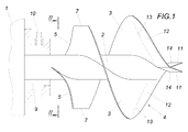
- the turbomachine according to the Fig. 1 is used as an agitator, which is used for example in a slurry tank, and has a driven by a submersible motor 1 propeller shaft 2, which carries two 180 ° out of phase arranged propeller blades 3, which is in the form of a coil with a full turn along the propeller shaft 2 extend.
- the drive of the propeller shaft 2 does not have to be done by a submersible motor 1 and can be made for example via a PTO.
- the suction edge 5 of the propeller blades 3 does not extend in a conventional manner in the radial direction, but in a sectional area 6 that runs tangentially to the propeller shaft 2, as shown in FIG Fig. 2 can be removed.
- this sectional surface 6 is a flat surface, which creates simple production conditions for the suction edge 5, because the propeller blades 3 are only to be trimmed along this flat sectional surface 6.
- the suction edges 5 do not extend to the outer edge of the propeller blades 3. Rather, the suction edges 5 merge into connecting edges 7, which essentially follow the line of intersection of the helical surface of the propeller blades 3 with a surface 8 parallel to the propeller shaft 2 but aligned transversely to the tangential cutting surface 6 ( Fig. 2 ), which in turn is advantageously flat.
- the arrangement is made such that the length of the suction edges 5 at least approximately corresponds to the length of the connecting edges 7.
- annular space 9 are provided, as shown in the Fig. 1 indicated by dash-dotted lines. Since this annular space 9 is connected via a connection 10 to an air intake line, 9 air is sucked from the annular space 9 via the propeller blades, which flows in the axial direction in the propeller 4 and intimately mixed with the also sucked liquid during the passage of the propeller 4 ,
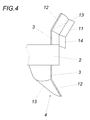
- the bending area is indicated by a line 13.
- the achievable with this deflection acceleration of the outflowing liquid flow is additionally enhanced by an angled end web 14 which forms the pressure edge 11 and extends in the sense of increasing the slope relative to the helical surface of the propeller blades 3 inclined.
- flow machines according to the invention can also be used advantageously as liquid pumps.
- a pump housing 15 which surrounds the outflow end of the propeller 4 and to the one delivery line 16 for the over the propeller. 4 ejected liquid can be connected so that the sucked for example via a suction port 17 according to the flow arrows 18 liquid is ejected at a corresponding delivery pressure in the delivery line 16.
- the pump housing 15 is connected to a submersible motor 1, via which the propeller shaft 2 is driven.
- the drive can also take place via a power take-off shaft or the like.
- the propeller 4 of the turbomachine used as a pump is substantially identical to the propeller 4 according to the Fig. 1 match, which is used as a stirrer.
- the submersible motor 1 is not connected to the suction side of the propeller 4, but on the opposite downstream side.
- a multi-bladed impeller 19 is connected to the propeller blades 3, which helps to redirect the axial fluid flow of the propeller 4 in a radial flow and eject into the radially attached delivery line 16.
- the angled end webs 14 are omitted in the region of the printed edges.
- the invention is of course not limited to the illustrated embodiments and can be modified in many ways, because it depends crucially on the course of the suction edge 5 and the subsequent connecting edge 7 of the propeller blades 3 in the formation of the propeller 4. However, this does not mean that the suction edge 5 extending substantially in a cutting surface 6 tangential to the propeller shaft 2 can not connect to a radial section of the suction edge.
Landscapes
- Chemical & Material Sciences (AREA)
- Chemical Kinetics & Catalysis (AREA)
- Engineering & Computer Science (AREA)
- Mechanical Engineering (AREA)
- General Engineering & Computer Science (AREA)
- Structures Of Non-Positive Displacement Pumps (AREA)
- Mixers Of The Rotary Stirring Type (AREA)
Abstract
Description
- Die Erfindung bezieht sich auf eine Strömungsmaschine für Flüssigkeiten mit einem angetriebenen Propeller, der wenigstens einen entlang einer Propellerwelle wendelförmig verlaufenden Propellerflügel mit einer Saug- und einer Druckkante aufweist.
- Um Strömungsmaschinen, die als Rührwerk zur Lufteintragung in Gülle eingesetzt werden, so zu verbessern, dass die Abhängigkeit der Luftansaugung von einem Luftspalt zwischen einer von der Propellerwelle durchsetzten Stirnwand und den Propellerflügeln vermieden wird, ist es bekannt (
AT 407 689 B - Der Erfindung liegt somit die Aufgabe zugrunde, eine Strömungsmaschine für Flüssigkeiten so auszugestalten, dass mit einfachen konstruktiven Maßnahmen eine merkliche Verbesserung der Förderleistung erzielt werden kann.
- Ausgehend von einer Strömungsmaschine der eingangs geschilderten Art löst die Erfindung die gestellte Aufgabe dadurch, dass die Saugkante des Propellerflügels zumindest angenähert entlang der Schnittlinie zwischen der Wendelfläche des Propellerflügels und einer zur Propellerwelle tangentialen Schnittfläche verläuft und dann in eine Verbindungskante übergeht, die im Wesentlichen der Schnittlinie der Wendelfläche mit einer zur Propellerwelle parallelen, quer zur tangentialen Schnittfläche ausgerichteten Fläche folgt.
- Durch den nicht mehr radial zur Rotorwelle ausgerichteten Verlauf der Saugkante des Propellerflügels in einer zur Propellerwelle tangentialen Schnittfläche werden im Zusammenwirken mit einer anschließenden Verbindungskante, die im Wesentlichen der Schnittlinie der Wendelfläche des Propellerflügels mit einer zur Propellerwelle parallelen, aber quer zur Schnittfläche der Saugkante verlaufenden Fläche folgt, in überraschender Weise gute Ansaugbedingungen sichergestellt, die für eine erhöhte Förderleistung der angesaugten Flüssigkeit sorgen, und zwar unabhängig davon, ob lediglich Flüssigkeit angesaugt oder in die angesaugte Flüssigkeit Luft eingetragen werden soll. Der Verlauf der Saugkante des Propellerflügels in einer zur Propellerwelle tangentialen Schnittfläche schließt allerdings einen radial zur Rotorwelle ausgerichteten Saugkantenabschnitt nicht aus, wiewohl mit einem solchen radialen Saugkantenabschnitt im Allgemeinen eine Verschlechterung der Ansaugverhältnisse in Kauf genommen werden muss.
- Besonders günstige Ansaugbedingungen ergeben sich in diesem Zusammenhang für die Strömungsmaschine, wenn die Saugkante und die anschließende Verbindungskante zum schraubenförmig verlaufenden Außenrand des Propellerflügels annähernd die gleiche Länge aufweisen.
- Eine Steigerung der Förderleistung und des gerichteten Ausstoßes wird möglich, wenn der Propellerflügel in einem mit der Druckkante endenden Umfangsbereich einen aus der Wendelfläche im Drehsinn des Propellers ausgebogenen Randabschnitt aufweist und wenn die Druckkante durch einen zusätzlichen, gegenüber der Wendelfläche und dem ausgebogenen Randabschnitt im Sinne einer Vergrößerung der Steigung abgewinkelten Endsteg des Propellerflügels gebildet wird. Durch den in einem abströmseitigen Umfangsbereich des Propellers in Drehrichtung aus der Wendelfläche des Propellerflügels ausgebogenen Randabschnitt wird die vom Propeller erfasste Strömung zusätzlich beschleunigt, wobei durch den die Druckkante des Propellerflügels bildenden, entsprechend geneigten Endsteg vermehrter Druck auf die abströmende Flüssigkeitsströmung ausgeübt wird. Durch die Summe dieser Maßnahmen kann daher ein vorteilhafter Propeller mit einem guten Wirkungsgrad zur Verfügung gestellt werden, insbesondere dann, wenn sich der aus der Wendelfläche ausgebogene Randabschnitt entlang eines Umfangbereichs von angenähert 90° erstreckt.
- Der Durchsatz durch den Propeller der Strömungsmaschine hängt unter anderem von der Anzahl der verwendeten Propellerflügel ab. Obwohl mit einem einzigen Propellerflügel durchaus ansprechende Förderleistungen erbracht werden können, ergeben sich besonders vorteilhafte Durchsatzbedingungen, wenn der Propeller zwei um 180° phasenversetzte Propellerflügel aufweist, weil in diesem Fall der Konstruktionsaufwand im Vergleich zu einem mehrflügeligen Propeller noch beschränkt bleibt.
- Aufgrund der guten Fördereigenschaften lassen sich erfindungsgemäße Strömungsmaschinen für unterschiedliche Zwecke vorteilhaft einsetzen. So ist es möglich, den leitringlosen Propeller als Rührwerk zu verwenden, indem der Propeller in die zu rührende Flüssigkeit, beispielsweise Gülle oder Abwässer, eingebracht wird, um die Flüssigkeit mit oder ohne zusätzliche Lufteintragung in eine Umwälzströmung zu versetzen. Es ist aber auch der Einsatz der erfindungsgemäßen Strömungsmaschine als Pumpe vorteilhaft. In diesem Fall ist durch ein Pumpengehäuse für eine Anschlussmöglichkeit einer Förderleitung für die gepumpte Flüssigkeit zu sorgen.
- In der Zeichnung ist der Erfindungsgegenstand beispielsweise dargestellt. Es zeigen
- Fig. 1
- einen ein Rührwerk bildenden Propeller einer erfindungsgemäßen Strömungsmaschine für Flüssigkeiten in einer schematischen Seitenansicht,
- Fig. 2
- einen Schnitt nach der Linie II-II der
Fig. 1 in einem kleineren Maßstab, - Fig. 3
- eine stirnseitige Ansicht des Propellers in einem kleineren Maßstab,
- Fig. 4
- einen Schnitt nach der Linie IV-IV der
Fig. 3 in einem größeren Maßstab, - Fig. 5
- eine als Pumpe dienende Strömungsmaschine in einem schematischen Längsschnitt und
- Fig. 6
- eine der
Fig. 5 entsprechende Darstellung Konstruktionsvariante einer erfindungsgemäßen Strömungsmaschine im Pumpeneinsatz - Die Strömungsmaschine gemäß der
Fig. 1 wird als Rührwerk verwendet, das zum Beispiel in einen Güllebehälter eingesetzt wird, und weist eine von einem Tauchmotor 1 angetriebene Propellerwelle 2 auf, die zwei um 180° phasenversetzt angeordnete Propellerflügel 3 trägt, die sich in Form einer Wendel mit einer vollen Windung entlang der Propellerwelle 2 erstrecken. Der Antrieb der Propellerwelle 2 muss jedoch keinesfalls durch einen Tauchmotor 1 erfolgen und kann beispielsweise über eine Zapfwelle vorgenommen werden. Damit sich für den durch die beiden Propellerflügel 3 gebildeten Propeller 4 vorteilhafte Ansaugbedingungen ergeben, verläuft die Saugkante 5 der Propellerflügel 3 nicht in herkömmlicher Weise in radialer Richtung, sondern in einer Schnittfläche 6, die tangential zur Propellerwelle 2 verläuft, wie dies derFig. 2 entnommen werden kann. Im Ausführungsbeispiel ist diese Schnittfläche 6 eine ebene Fläche, was einfache Herstellungsbedingungen für die Saugkante 5 schafft, weil die Propellerflügel 3 lediglich entlang dieser ebenen Schnittfläche 6 zu besäumen sind. - Aus den
Fig. 1 und2 ist zu entnehmen, dass die Saugkanten 5 nicht bis zum Außenrand der Propellerflügel 3 verlaufen. Die Saugkanten 5 gehen vielmehr in Verbindungskanten 7 über, die im Wesentlichen der Schnittlinie der Wendelfläche der Propellerflügel 3 mit einer zur Propellerwelle 2 parallelen, aber quer zur tangentialen Schnittfläche 6 ausgerichteten Fläche 8 folgen (Fig. 2 ), die wiederum vorteilhaft eben ist. Die Anordnung ist dabei so getroffen, dass die Länge der Saugkanten 5 zumindest angenähert der Länge der Verbindungskanten 7 entspricht. Mit einer solchen Ausbildung der Einströmseite des Propellers 4 können mit einfachen konstruktiven Mitteln vorteilhafte Ansaugbedingungen geschaffen werden, und zwar nicht nur für die Flüssigkeit, in die das Rührwerk eingesetzt wird, sondern auch für den Fall dass in die Flüssigkeit Luft eingetragen werden soll. - Zu diesem Zweck kann auf der dem Tauchmotor 1 zugekehrten Saugseite des Propellers 4 ein von der Propellerwelle 2 durchsetzter Ringraum 9 vorgesehen werden, wie dies in der
Fig. 1 strichpunktiert angedeutet ist. Da dieser Ringraum 9 über einen Anschluss 10 an eine Luftansaugleitung angeschlossen ist, wird über die Propellerflügel 3 aus dem Ringraum 9 Luft angesaugt, die in axialer Richtung in den Propeller 4 strömt und sich mit der ebenfalls angesaugten Flüssigkeit während des Durchströmens des Propellers 4 innig mischt. - Die mit Hilfe der Propellerflügel 3 in axialer Richtung durch den Propeller 4 geförderte, allenfalls mit Luft angereicherte Flüssigkeitsströmung kann auf der Ausströmseite des Propellers 4 zusätzlich beschleunigt werden. Hierfür bilden die Propellerflügel 3 in einem mit einer Druckkante 11 abgeschlossenen Umfangsbereich von im Wesentlichen 90° einen Randabschnitt 12, der aus der Wendelfläche des jeweiligen Propellerflügels 3 im Drehsinn des Propellers 4 ausgebogen ist, wie dies insbesondere die
Fig. 3 und4 erkennen lassen. Der Biegebereich ist dabei durch eine Linie 13 angedeutet. Die mit dieser Ausbiegung erreichbare Beschleunigung des ausströmenden Flüssigkeitsstromes wird zusätzlich durch einen abgewinkelten Endsteg 14 verstärkt, der die Druckkante 11 bildet und im Sinne einer Vergrößerung der Steigung gegenüber der Wendelfläche der Propellerflügel 3 geneigt verläuft. Durch diese ausströmseitigen Maßnahmen wird der Ausstoß der Flüssigkeit bzw. des Flüssigkeit-Luftgemisches aus dem Rührwerk und damit die Rührwirkung innerhalb des das Rührwerk aufnehmenden Behälters entsprechend unterstützt. - Wie den Ausführungsbeispielen der
Fig. 5 und6 entnommen werden kann, können erfindungsgemäße Strömungsmaschinen auch vorteilhaft als Flüssigkeitspumpen eingesetzt werden. Zu diesem Zweck braucht ja lediglich ein Pumpengehäuse 15 vorgesehen zu werden, das das Abströmende des Propellers 4 umschließt und an das eine Förderleitung 16 für die über den Propeller 4 ausgestoßene Flüssigkeit angeschlossen werden kann, sodass die beispielsweise über eine Ansaugöffnung 17 gemäß den Strömungspfeilen 18 angesaugte Flüssigkeit unter einem entsprechenden Förderdruck in die Förderleitung 16 ausgestoßen wird. Gemäß dem Ausführungsbeispiel nach derFig. 5 wird das Pumpengehäuse 15 an einen Tauchmotor 1 angeschlossen, über den die Propellerwelle 2 angetrieben wird. Der Antrieb kann selbstverständlich auch über eine Zapfwelle oder dgl. erfolgen. Der Propeller 4 der als Pumpe eingesetzten Strömungsmaschine stimmt im Wesentlichen mit dem Propeller 4 gemäß derFig. 1 überein, der als Rührwerk eingesetzt wird. - Zum Unterschied zu der
Fig. 5 wird gemäß dem Ausführungsbeispiel nach derFig. 6 der Tauchmotor 1 nicht an der Ansaugseite des Propellers 4, sondern auf der gegenüberliegenden Abströmseite angeschlossen. Außerdem ist an die Propellerflügel 3 ein mehrflügeliges Pumpenrad 19 angeschlossen, das hilft, die axiale Flüssigkeitsströmung des Propellers 4 in eine radiale Strömung umzulenken und in die radial angesetzte Förderleitung 16 auszustoßen. In diesem Fall entfallen die abgewinkelten Endstege 14 im Bereich der Druckkanten. - Die Erfindung ist selbstverständlich nicht auf die dargestellten Ausführungsbeispiele beschränkt und kann in vielfältiger Weise abgewandelt werden, weil es bei der Ausbildung des Propellers 4 entscheidend auf den Verlauf der Saugkante 5 und der anschließenden Verbindungskante 7 der Propellerflügel 3 ankommt. Dies bedeutet aber nicht, dass die im Wesentlichen in einer zur Propellerwelle 2 tangentialen Schnittfläche 6 verlaufende Saugkante 5 nicht an einen radialen Abschnitt der Saugkante anschließen kann.
Claims (7)
- Strömungsmaschine für Flüssigkeiten mit einem angetriebenen Propeller (4), der wenigstens einen entlang einer Propellerwelle (2) wendelförmig verlaufenden Propellerflügel (3) mit einer Saug- und einer Druckkante (5, 11) aufweist, dadurch gekennzeichnet, dass die Saugkante (5) des Propellerflügels (3) zumindest angenähert entlang der Schnittlinie zwischen der Wendelfläche des Propellerflügels (3) und einer zur Propellerwelle (2) tangentialen Schnittfläche (6) verläuft und dann in eine Verbindungskante (7) übergeht, die im Wesentlichen der Schnittlinie der Wendelfläche mit einer zur Propellerwelle (2) parallelen, quer zur tangentialen Schnittfläche (6) ausgerichteten Fläche (8) folgt.
- Strömungsmaschine Anspruch 1, dadurch gekennzeichnet, dass die Saugkante (5) und die Verbindungskante (7) angenähert die gleiche Länge aufweisen.
- Strömungsmaschine nach Anspruch 1 oder 2, dadurch gekennzeichnet, dass der Propellerflügel (3) in einem mit der Druckkante (11) endenden Umfangsbereich einen aus der Wendelfläche im Drehsinn des Propellers (4) ausgebogenen Randabschnitt (12) aufweist und dass ein gegenüber der Wendelfläche und dem ausgebogenen Randabschnitt (12) im Sinne einer Vergrößerung der Steigung abgewinkelter Endsteg (14) des Propellerflügels (3) die Druckkante (11) bildet.
- Strömungsmaschine nach Anspruch 3, dadurch gekennzeichnet, dass sich der aus der Wendelfläche ausgebogene Randabschnitt (12) entlang eines Umfangbereichs von angenähert 90° erstreckt.
- Strömungsmaschine nach einem der Ansprüche 1 bis 4, dadurch gekennzeichnet, dass der Propeller (4) zwei um 180° phasenversetzte Propellerflügel (3) aufweist.
- Strömungsmaschine nach einem der Ansprüche 1 bis 5, dadurch gekennzeichnet, dass der Propeller (4) ein Rührwerk bildet.
- Strömungsmaschine nach einem der Ansprüche 1 bis 5, dadurch gekennzeichnet, dass der Propeller den Rotor einer Pumpe bildet.
Priority Applications (1)
| Application Number | Priority Date | Filing Date | Title |
|---|---|---|---|
| PL14150738T PL2754344T3 (pl) | 2013-01-15 | 2014-01-10 | Maszyna przepływowa dla cieczy |
Applications Claiming Priority (1)
| Application Number | Priority Date | Filing Date | Title |
|---|---|---|---|
| ATA50018/2013A AT513152B1 (de) | 2013-01-15 | 2013-01-15 | Rührwerk für Flüssigkeiten, insbesondere für Gülle |
Publications (3)
| Publication Number | Publication Date |
|---|---|
| EP2754344A2 true EP2754344A2 (de) | 2014-07-16 |
| EP2754344A3 EP2754344A3 (de) | 2015-02-18 |
| EP2754344B1 EP2754344B1 (de) | 2016-09-21 |
Family
ID=49943197
Family Applications (1)
| Application Number | Title | Priority Date | Filing Date |
|---|---|---|---|
| EP14150738.4A Active EP2754344B1 (de) | 2013-01-15 | 2014-01-10 | Strömungsmaschine für Flüssigkeiten |
Country Status (3)
| Country | Link |
|---|---|
| EP (1) | EP2754344B1 (de) |
| AT (1) | AT513152B1 (de) |
| PL (1) | PL2754344T3 (de) |
Family Cites Families (7)
| Publication number | Priority date | Publication date | Assignee | Title |
|---|---|---|---|---|
| BE463837A (de) * | ||||
| US3945761A (en) * | 1971-09-02 | 1976-03-23 | Toshinobu Araoka | Fan disturbing sand at the bottom of a body of water so that it may be pumped up efficiently |
| AT348953B (de) * | 1977-08-26 | 1979-03-12 | Alfa Laval Stalltech | Vorrichtung zur begasung und umwaelzung von fluessigkeiten |
| US4647215A (en) * | 1983-09-19 | 1987-03-03 | Envirotech Corporation | Ragless propeller draft tube mixer |
| AT398171B (de) * | 1992-04-22 | 1994-10-25 | Gritzner Gottfried | Rührwerk zum eintragen von luft in flüssigkeiten, insbesondere in gülle |
| AT407689B (de) * | 1994-04-18 | 2001-05-25 | Gritzner Gottfried | Rührwerk zum eintragen von luft in flüssigkeit, insbesondere in gülle |
| GB0318449D0 (en) * | 2003-08-06 | 2003-09-10 | Glaxo Group Ltd | Impeller unit |
-
2013
- 2013-01-15 AT ATA50018/2013A patent/AT513152B1/de not_active IP Right Cessation
-
2014
- 2014-01-10 PL PL14150738T patent/PL2754344T3/pl unknown
- 2014-01-10 EP EP14150738.4A patent/EP2754344B1/de active Active
Also Published As
| Publication number | Publication date |
|---|---|
| PL2754344T3 (pl) | 2017-04-28 |
| EP2754344B1 (de) | 2016-09-21 |
| AT513152A4 (de) | 2014-02-15 |
| AT513152B1 (de) | 2014-02-15 |
| EP2754344A3 (de) | 2015-02-18 |
Similar Documents
| Publication | Publication Date | Title |
|---|---|---|
| EP2495444B1 (de) | Pumpe | |
| EP3008346B1 (de) | Pumpe | |
| DE69023699T2 (de) | Selbstansaugende Kreiselpumpe. | |
| EP2188532B1 (de) | Pumpenlaufrad und pumpe umfassend ein derartiges pumpenlaufrad | |
| DE102012216196A1 (de) | Pumpe | |
| AT402842B (de) | Vorrichtung zum pumpen von pülpe | |
| EP4206470A1 (de) | Pumpenlaufrad, gehäuseelement und pumpe hiermit | |
| WO2014090559A2 (de) | Pumpvorrichtung mit einem strömungsleitelement | |
| WO2022263370A1 (de) | Pumpe und ein fahrzeug mit einer solchen pumpe | |
| DE1728419A1 (de) | Fluessigkeitsringverdichter | |
| EP2582983B1 (de) | Doppelflutige kreiselpumpe | |
| EP2754344B1 (de) | Strömungsmaschine für Flüssigkeiten | |
| EP1021655B1 (de) | Förderpumpe | |
| EP1131560B1 (de) | Seitenkanalpumpe | |
| DE60311165T2 (de) | Kreiselpumpe für niedrige Flussraten mit verbesserter Ansaughöhe | |
| EP1344944A1 (de) | Kreiselpumpe mit Zerkleinerungseinrichtung | |
| EP4615626A2 (de) | Homogenisator sowie vakuumprozessanlage und verfahren damit | |
| WO2022189489A1 (de) | Kreiselpumpe mit einlaufrippen | |
| EP2480321B1 (de) | Axialwirkendes rührorgan | |
| DE102010004379A1 (de) | Kraftstoffpumpe | |
| EP2049801B1 (de) | Förderpumpe mit filter | |
| DE102023118148B3 (de) | Kreiselpumpe | |
| EP3303844B1 (de) | Laufrad für eine kreiselpumpe und kreiselpumpe | |
| EP2420677A1 (de) | Mehrstufige Kreiselpumpe | |
| EP2205850A1 (de) | Kraftstoffpumpe zum fördern von kraftstoff aus einem vorratsbehälter zu einer brennkraftmaschine |
Legal Events
| Date | Code | Title | Description |
|---|---|---|---|
| PUAI | Public reference made under article 153(3) epc to a published international application that has entered the european phase |
Free format text: ORIGINAL CODE: 0009012 |
|
| 17P | Request for examination filed |
Effective date: 20140110 |
|
| AK | Designated contracting states |
Kind code of ref document: A2 Designated state(s): AL AT BE BG CH CY CZ DE DK EE ES FI FR GB GR HR HU IE IS IT LI LT LU LV MC MK MT NL NO PL PT RO RS SE SI SK SM TR |
|
| AX | Request for extension of the european patent |
Extension state: BA ME |
|
| PUAL | Search report despatched |
Free format text: ORIGINAL CODE: 0009013 |
|
| AK | Designated contracting states |
Kind code of ref document: A3 Designated state(s): AL AT BE BG CH CY CZ DE DK EE ES FI FR GB GR HR HU IE IS IT LI LT LU LV MC MK MT NL NO PL PT RO RS SE SI SK SM TR |
|
| AX | Request for extension of the european patent |
Extension state: BA ME |
|
| RIC1 | Information provided on ipc code assigned before grant |
Ipc: A01C 3/02 20060101AFI20150114BHEP Ipc: F04D 29/18 20060101ALI20150114BHEP Ipc: B01F 3/04 20060101ALI20150114BHEP Ipc: B01F 7/00 20060101ALI20150114BHEP Ipc: B01F 7/06 20060101ALI20150114BHEP |
|
| R17P | Request for examination filed (corrected) |
Effective date: 20150817 |
|
| RBV | Designated contracting states (corrected) |
Designated state(s): AL AT BE BG CH CY CZ DE DK EE ES FI FR GB GR HR HU IE IS IT LI LT LU LV MC MK MT NL NO PL PT RO RS SE SI SK SM TR |
|
| GRAP | Despatch of communication of intention to grant a patent |
Free format text: ORIGINAL CODE: EPIDOSNIGR1 |
|
| RIC1 | Information provided on ipc code assigned before grant |
Ipc: B01F 7/06 20060101ALI20160301BHEP Ipc: B01F 7/00 20060101ALI20160301BHEP Ipc: F04D 29/22 20060101ALI20160301BHEP Ipc: A01C 3/02 20060101AFI20160301BHEP Ipc: F04D 29/18 20060101ALI20160301BHEP Ipc: B01F 3/04 20060101ALI20160301BHEP |
|
| INTG | Intention to grant announced |
Effective date: 20160406 |
|
| GRAS | Grant fee paid |
Free format text: ORIGINAL CODE: EPIDOSNIGR3 |
|
| GRAA | (expected) grant |
Free format text: ORIGINAL CODE: 0009210 |
|
| AK | Designated contracting states |
Kind code of ref document: B1 Designated state(s): AL AT BE BG CH CY CZ DE DK EE ES FI FR GB GR HR HU IE IS IT LI LT LU LV MC MK MT NL NO PL PT RO RS SE SI SK SM TR |
|
| REG | Reference to a national code |
Ref country code: GB Ref legal event code: FG4D Free format text: NOT ENGLISH |
|
| REG | Reference to a national code |
Ref country code: CH Ref legal event code: EP |
|
| REG | Reference to a national code |
Ref country code: AT Ref legal event code: REF Ref document number: 830245 Country of ref document: AT Kind code of ref document: T Effective date: 20161015 |
|
| REG | Reference to a national code |
Ref country code: IE Ref legal event code: FG4D Free format text: LANGUAGE OF EP DOCUMENT: GERMAN |
|
| REG | Reference to a national code |
Ref country code: DE Ref legal event code: R096 Ref document number: 502014001474 Country of ref document: DE |
|
| REG | Reference to a national code |
Ref country code: CH Ref legal event code: NV Representative=s name: E. BLUM AND CO. AG PATENT- UND MARKENANWAELTE , CH |
|
| REG | Reference to a national code |
Ref country code: NL Ref legal event code: FP |
|
| REG | Reference to a national code |
Ref country code: LT Ref legal event code: MG4D |
|
| REG | Reference to a national code |
Ref country code: FR Ref legal event code: PLFP Year of fee payment: 4 |
|
| PG25 | Lapsed in a contracting state [announced via postgrant information from national office to epo] |
Ref country code: FI Free format text: LAPSE BECAUSE OF FAILURE TO SUBMIT A TRANSLATION OF THE DESCRIPTION OR TO PAY THE FEE WITHIN THE PRESCRIBED TIME-LIMIT Effective date: 20160921 Ref country code: NO Free format text: LAPSE BECAUSE OF FAILURE TO SUBMIT A TRANSLATION OF THE DESCRIPTION OR TO PAY THE FEE WITHIN THE PRESCRIBED TIME-LIMIT Effective date: 20161221 Ref country code: RS Free format text: LAPSE BECAUSE OF FAILURE TO SUBMIT A TRANSLATION OF THE DESCRIPTION OR TO PAY THE FEE WITHIN THE PRESCRIBED TIME-LIMIT Effective date: 20160921 Ref country code: LT Free format text: LAPSE BECAUSE OF FAILURE TO SUBMIT A TRANSLATION OF THE DESCRIPTION OR TO PAY THE FEE WITHIN THE PRESCRIBED TIME-LIMIT Effective date: 20160921 |
|
| PG25 | Lapsed in a contracting state [announced via postgrant information from national office to epo] |
Ref country code: GR Free format text: LAPSE BECAUSE OF FAILURE TO SUBMIT A TRANSLATION OF THE DESCRIPTION OR TO PAY THE FEE WITHIN THE PRESCRIBED TIME-LIMIT Effective date: 20161222 Ref country code: LV Free format text: LAPSE BECAUSE OF FAILURE TO SUBMIT A TRANSLATION OF THE DESCRIPTION OR TO PAY THE FEE WITHIN THE PRESCRIBED TIME-LIMIT Effective date: 20160921 Ref country code: SE Free format text: LAPSE BECAUSE OF FAILURE TO SUBMIT A TRANSLATION OF THE DESCRIPTION OR TO PAY THE FEE WITHIN THE PRESCRIBED TIME-LIMIT Effective date: 20160921 |
|
| PG25 | Lapsed in a contracting state [announced via postgrant information from national office to epo] |
Ref country code: RO Free format text: LAPSE BECAUSE OF FAILURE TO SUBMIT A TRANSLATION OF THE DESCRIPTION OR TO PAY THE FEE WITHIN THE PRESCRIBED TIME-LIMIT Effective date: 20160921 Ref country code: EE Free format text: LAPSE BECAUSE OF FAILURE TO SUBMIT A TRANSLATION OF THE DESCRIPTION OR TO PAY THE FEE WITHIN THE PRESCRIBED TIME-LIMIT Effective date: 20160921 |
|
| PG25 | Lapsed in a contracting state [announced via postgrant information from national office to epo] |
Ref country code: IS Free format text: LAPSE BECAUSE OF FAILURE TO SUBMIT A TRANSLATION OF THE DESCRIPTION OR TO PAY THE FEE WITHIN THE PRESCRIBED TIME-LIMIT Effective date: 20170121 Ref country code: SK Free format text: LAPSE BECAUSE OF FAILURE TO SUBMIT A TRANSLATION OF THE DESCRIPTION OR TO PAY THE FEE WITHIN THE PRESCRIBED TIME-LIMIT Effective date: 20160921 Ref country code: BG Free format text: LAPSE BECAUSE OF FAILURE TO SUBMIT A TRANSLATION OF THE DESCRIPTION OR TO PAY THE FEE WITHIN THE PRESCRIBED TIME-LIMIT Effective date: 20161221 Ref country code: CZ Free format text: LAPSE BECAUSE OF FAILURE TO SUBMIT A TRANSLATION OF THE DESCRIPTION OR TO PAY THE FEE WITHIN THE PRESCRIBED TIME-LIMIT Effective date: 20160921 Ref country code: SM Free format text: LAPSE BECAUSE OF FAILURE TO SUBMIT A TRANSLATION OF THE DESCRIPTION OR TO PAY THE FEE WITHIN THE PRESCRIBED TIME-LIMIT Effective date: 20160921 Ref country code: ES Free format text: LAPSE BECAUSE OF FAILURE TO SUBMIT A TRANSLATION OF THE DESCRIPTION OR TO PAY THE FEE WITHIN THE PRESCRIBED TIME-LIMIT Effective date: 20160921 Ref country code: PT Free format text: LAPSE BECAUSE OF FAILURE TO SUBMIT A TRANSLATION OF THE DESCRIPTION OR TO PAY THE FEE WITHIN THE PRESCRIBED TIME-LIMIT Effective date: 20170123 |
|
| REG | Reference to a national code |
Ref country code: DE Ref legal event code: R097 Ref document number: 502014001474 Country of ref document: DE |
|
| PLBE | No opposition filed within time limit |
Free format text: ORIGINAL CODE: 0009261 |
|
| STAA | Information on the status of an ep patent application or granted ep patent |
Free format text: STATUS: NO OPPOSITION FILED WITHIN TIME LIMIT |
|
| PG25 | Lapsed in a contracting state [announced via postgrant information from national office to epo] |
Ref country code: DK Free format text: LAPSE BECAUSE OF FAILURE TO SUBMIT A TRANSLATION OF THE DESCRIPTION OR TO PAY THE FEE WITHIN THE PRESCRIBED TIME-LIMIT Effective date: 20160921 |
|
| 26N | No opposition filed |
Effective date: 20170622 |
|
| PG25 | Lapsed in a contracting state [announced via postgrant information from national office to epo] |
Ref country code: MC Free format text: LAPSE BECAUSE OF FAILURE TO SUBMIT A TRANSLATION OF THE DESCRIPTION OR TO PAY THE FEE WITHIN THE PRESCRIBED TIME-LIMIT Effective date: 20160921 |
|
| REG | Reference to a national code |
Ref country code: IE Ref legal event code: MM4A |
|
| PG25 | Lapsed in a contracting state [announced via postgrant information from national office to epo] |
Ref country code: SI Free format text: LAPSE BECAUSE OF FAILURE TO SUBMIT A TRANSLATION OF THE DESCRIPTION OR TO PAY THE FEE WITHIN THE PRESCRIBED TIME-LIMIT Effective date: 20160921 Ref country code: LU Free format text: LAPSE BECAUSE OF NON-PAYMENT OF DUE FEES Effective date: 20170110 |
|
| REG | Reference to a national code |
Ref country code: FR Ref legal event code: PLFP Year of fee payment: 5 |
|
| PG25 | Lapsed in a contracting state [announced via postgrant information from national office to epo] |
Ref country code: IE Free format text: LAPSE BECAUSE OF NON-PAYMENT OF DUE FEES Effective date: 20170110 |
|
| PG25 | Lapsed in a contracting state [announced via postgrant information from national office to epo] |
Ref country code: MT Free format text: LAPSE BECAUSE OF FAILURE TO SUBMIT A TRANSLATION OF THE DESCRIPTION OR TO PAY THE FEE WITHIN THE PRESCRIBED TIME-LIMIT Effective date: 20160921 |
|
| PG25 | Lapsed in a contracting state [announced via postgrant information from national office to epo] |
Ref country code: AL Free format text: LAPSE BECAUSE OF FAILURE TO SUBMIT A TRANSLATION OF THE DESCRIPTION OR TO PAY THE FEE WITHIN THE PRESCRIBED TIME-LIMIT Effective date: 20160921 |
|
| PG25 | Lapsed in a contracting state [announced via postgrant information from national office to epo] |
Ref country code: HU Free format text: LAPSE BECAUSE OF FAILURE TO SUBMIT A TRANSLATION OF THE DESCRIPTION OR TO PAY THE FEE WITHIN THE PRESCRIBED TIME-LIMIT; INVALID AB INITIO Effective date: 20140110 |
|
| PG25 | Lapsed in a contracting state [announced via postgrant information from national office to epo] |
Ref country code: CY Free format text: LAPSE BECAUSE OF NON-PAYMENT OF DUE FEES Effective date: 20160921 |
|
| PG25 | Lapsed in a contracting state [announced via postgrant information from national office to epo] |
Ref country code: MK Free format text: LAPSE BECAUSE OF FAILURE TO SUBMIT A TRANSLATION OF THE DESCRIPTION OR TO PAY THE FEE WITHIN THE PRESCRIBED TIME-LIMIT Effective date: 20160921 |
|
| PG25 | Lapsed in a contracting state [announced via postgrant information from national office to epo] |
Ref country code: TR Free format text: LAPSE BECAUSE OF FAILURE TO SUBMIT A TRANSLATION OF THE DESCRIPTION OR TO PAY THE FEE WITHIN THE PRESCRIBED TIME-LIMIT Effective date: 20160921 |
|
| PG25 | Lapsed in a contracting state [announced via postgrant information from national office to epo] |
Ref country code: HR Free format text: LAPSE BECAUSE OF FAILURE TO SUBMIT A TRANSLATION OF THE DESCRIPTION OR TO PAY THE FEE WITHIN THE PRESCRIBED TIME-LIMIT Effective date: 20160921 |
|
| PGFP | Annual fee paid to national office [announced via postgrant information from national office to epo] |
Ref country code: PL Payment date: 20221229 Year of fee payment: 10 |
|
| PGFP | Annual fee paid to national office [announced via postgrant information from national office to epo] |
Ref country code: FR Payment date: 20230124 Year of fee payment: 10 |
|
| PGFP | Annual fee paid to national office [announced via postgrant information from national office to epo] |
Ref country code: GB Payment date: 20230124 Year of fee payment: 10 Ref country code: BE Payment date: 20230124 Year of fee payment: 10 |
|
| P01 | Opt-out of the competence of the unified patent court (upc) registered |
Effective date: 20230327 |
|
| PGFP | Annual fee paid to national office [announced via postgrant information from national office to epo] |
Ref country code: NL Payment date: 20230124 Year of fee payment: 10 |
|
| REG | Reference to a national code |
Ref country code: NL Ref legal event code: MM Effective date: 20240201 |
|
| GBPC | Gb: european patent ceased through non-payment of renewal fee |
Effective date: 20240110 |
|
| PG25 | Lapsed in a contracting state [announced via postgrant information from national office to epo] |
Ref country code: GB Free format text: LAPSE BECAUSE OF NON-PAYMENT OF DUE FEES Effective date: 20240110 |
|
| PG25 | Lapsed in a contracting state [announced via postgrant information from national office to epo] |
Ref country code: BE Free format text: LAPSE BECAUSE OF NON-PAYMENT OF DUE FEES Effective date: 20240131 |
|
| PG25 | Lapsed in a contracting state [announced via postgrant information from national office to epo] |
Ref country code: FR Free format text: LAPSE BECAUSE OF NON-PAYMENT OF DUE FEES Effective date: 20240131 |
|
| PG25 | Lapsed in a contracting state [announced via postgrant information from national office to epo] |
Ref country code: NL Free format text: LAPSE BECAUSE OF NON-PAYMENT OF DUE FEES Effective date: 20240201 |
|
| PG25 | Lapsed in a contracting state [announced via postgrant information from national office to epo] |
Ref country code: NL Free format text: LAPSE BECAUSE OF NON-PAYMENT OF DUE FEES Effective date: 20240201 Ref country code: GB Free format text: LAPSE BECAUSE OF NON-PAYMENT OF DUE FEES Effective date: 20240110 Ref country code: FR Free format text: LAPSE BECAUSE OF NON-PAYMENT OF DUE FEES Effective date: 20240131 Ref country code: BE Free format text: LAPSE BECAUSE OF NON-PAYMENT OF DUE FEES Effective date: 20240131 |
|
| REG | Reference to a national code |
Ref country code: BE Ref legal event code: MM Effective date: 20240131 |
|
| PG25 | Lapsed in a contracting state [announced via postgrant information from national office to epo] |
Ref country code: PL Free format text: LAPSE BECAUSE OF NON-PAYMENT OF DUE FEES Effective date: 20240110 |
|
| REG | Reference to a national code |
Ref country code: CH Ref legal event code: U11 Free format text: ST27 STATUS EVENT CODE: U-0-0-U10-U11 (AS PROVIDED BY THE NATIONAL OFFICE) Effective date: 20260201 |
|
| PGFP | Annual fee paid to national office [announced via postgrant information from national office to epo] |
Ref country code: DE Payment date: 20260120 Year of fee payment: 13 |
|
| PGFP | Annual fee paid to national office [announced via postgrant information from national office to epo] |
Ref country code: AT Payment date: 20260120 Year of fee payment: 13 |
|
| PGFP | Annual fee paid to national office [announced via postgrant information from national office to epo] |
Ref country code: IT Payment date: 20260123 Year of fee payment: 13 |
|
| PGFP | Annual fee paid to national office [announced via postgrant information from national office to epo] |
Ref country code: CH Payment date: 20260201 Year of fee payment: 13 |