EP2754464A1 - Implantierbare elektronische Vorrichtung - Google Patents
Implantierbare elektronische Vorrichtung Download PDFInfo
- Publication number
- EP2754464A1 EP2754464A1 EP13305037.7A EP13305037A EP2754464A1 EP 2754464 A1 EP2754464 A1 EP 2754464A1 EP 13305037 A EP13305037 A EP 13305037A EP 2754464 A1 EP2754464 A1 EP 2754464A1
- Authority
- EP
- European Patent Office
- Prior art keywords
- electric shock
- deploying
- electronic unit
- main electronic
- fibrillation
- Prior art date
- Legal status (The legal status is an assumption and is not a legal conclusion. Google has not performed a legal analysis and makes no representation as to the accuracy of the status listed.)
- Withdrawn
Links
- 241000124008 Mammalia Species 0.000 claims abstract description 30
- 206010061592 cardiac fibrillation Diseases 0.000 claims abstract description 19
- 230000002600 fibrillogenic effect Effects 0.000 claims abstract description 19
- 230000001939 inductive effect Effects 0.000 claims abstract description 5
- 210000005241 right ventricle Anatomy 0.000 claims abstract description 3
- 238000004891 communication Methods 0.000 claims description 11
- 230000001133 acceleration Effects 0.000 claims description 6
- 230000004913 activation Effects 0.000 claims description 6
- 230000009849 deactivation Effects 0.000 claims description 3
- 230000008520 organization Effects 0.000 claims 2
- 230000000063 preceeding effect Effects 0.000 claims 1
- 206010015548 Euthanasia Diseases 0.000 description 6
- 238000005259 measurement Methods 0.000 description 4
- 210000000056 organ Anatomy 0.000 description 4
- 230000000694 effects Effects 0.000 description 3
- CURLTUGMZLYLDI-UHFFFAOYSA-N Carbon dioxide Chemical compound O=C=O CURLTUGMZLYLDI-UHFFFAOYSA-N 0.000 description 2
- 206010010144 Completed suicide Diseases 0.000 description 2
- 210000000038 chest Anatomy 0.000 description 2
- 238000001514 detection method Methods 0.000 description 2
- 230000004807 localization Effects 0.000 description 2
- 230000007257 malfunction Effects 0.000 description 2
- 239000000203 mixture Substances 0.000 description 2
- 238000012360 testing method Methods 0.000 description 2
- 239000003440 toxic substance Substances 0.000 description 2
- WHXSMMKQMYFTQS-UHFFFAOYSA-N Lithium Chemical compound [Li] WHXSMMKQMYFTQS-UHFFFAOYSA-N 0.000 description 1
- RTAQQCXQSZGOHL-UHFFFAOYSA-N Titanium Chemical compound [Ti] RTAQQCXQSZGOHL-UHFFFAOYSA-N 0.000 description 1
- 239000008280 blood Substances 0.000 description 1
- 210000004369 blood Anatomy 0.000 description 1
- 230000036760 body temperature Effects 0.000 description 1
- 229910002092 carbon dioxide Inorganic materials 0.000 description 1
- 239000001569 carbon dioxide Substances 0.000 description 1
- 230000008602 contraction Effects 0.000 description 1
- 230000001862 defibrillatory effect Effects 0.000 description 1
- 230000001419 dependent effect Effects 0.000 description 1
- 238000013461 design Methods 0.000 description 1
- 201000010099 disease Diseases 0.000 description 1
- 208000037265 diseases, disorders, signs and symptoms Diseases 0.000 description 1
- 230000002349 favourable effect Effects 0.000 description 1
- 238000002513 implantation Methods 0.000 description 1
- 230000035987 intoxication Effects 0.000 description 1
- 231100000566 intoxication Toxicity 0.000 description 1
- 229910052744 lithium Inorganic materials 0.000 description 1
- 239000000463 material Substances 0.000 description 1
- 229910052751 metal Inorganic materials 0.000 description 1
- 239000002184 metal Substances 0.000 description 1
- 150000002739 metals Chemical class 0.000 description 1
- 238000000034 method Methods 0.000 description 1
- 230000000926 neurological effect Effects 0.000 description 1
- 230000000422 nocturnal effect Effects 0.000 description 1
- 231100000614 poison Toxicity 0.000 description 1
- 230000002265 prevention Effects 0.000 description 1
- 230000033764 rhythmic process Effects 0.000 description 1
- 239000010936 titanium Substances 0.000 description 1
- 229910052719 titanium Inorganic materials 0.000 description 1
- 231100000167 toxic agent Toxicity 0.000 description 1
- 230000001960 triggered effect Effects 0.000 description 1
Images

Classifications
-
- A—HUMAN NECESSITIES
- A61—MEDICAL OR VETERINARY SCIENCE; HYGIENE
- A61N—ELECTROTHERAPY; MAGNETOTHERAPY; RADIATION THERAPY; ULTRASOUND THERAPY
- A61N1/00—Electrotherapy; Circuits therefor
- A61N1/18—Applying electric currents by contact electrodes
- A61N1/32—Applying electric currents by contact electrodes alternating or intermittent currents
- A61N1/36—Applying electric currents by contact electrodes alternating or intermittent currents for stimulation
- A61N1/372—Arrangements in connection with the implantation of stimulators
- A61N1/37211—Means for communicating with stimulators
- A61N1/37252—Details of algorithms or data aspects of communication system, e.g. handshaking, transmitting specific data or segmenting data
- A61N1/37282—Details of algorithms or data aspects of communication system, e.g. handshaking, transmitting specific data or segmenting data characterised by communication with experts in remote locations using a network
-
- A—HUMAN NECESSITIES
- A61—MEDICAL OR VETERINARY SCIENCE; HYGIENE
- A61N—ELECTROTHERAPY; MAGNETOTHERAPY; RADIATION THERAPY; ULTRASOUND THERAPY
- A61N1/00—Electrotherapy; Circuits therefor
- A61N1/18—Applying electric currents by contact electrodes
- A61N1/32—Applying electric currents by contact electrodes alternating or intermittent currents
- A61N1/38—Applying electric currents by contact electrodes alternating or intermittent currents for producing shock effects
- A61N1/385—Devices for inducing an abnormal cardiac function, e.g. fibrillation
Definitions
- the invention is directed to an implantable electronic device for delivering electric shocks to intentionally induce a fibrillation according to the preamble of the independent claim.
- euthanasia Medically assisted suicide has been accepted by a wide fraction of the population. In countries such as Switzerland euthanasia is provided e.g. by associations. In France, according to recent polls, 80% of the inhabitants are favourable to euthanasia. Furthermore, euthanasia is practiced frequently with mammals such as pets which suffer from disease or pain and for which no treatment is available or possible. However, bringing pets to a veterinarian doctor for this purpose may cause unnecessary stress to the mammal and/or to the person responsible for the mammal.
- composition which leads to a humane euthanasia of a mammal. This composition has to be applied by physician and can not be used by person himself.
- defibrillators which are implanted inside the body of a patient.
- the defibrillator induces electric shocks into the heart to stop the fibrillation and re-create a normal heart rhythm.
- Such a device is for example disclosed in EP 0 773 039 . Due to the shape of the wave of the electric shock, this device is suited for intentionally defibrillating the heart.
- the object is accomplished by an implantable electronic device for delivering electric shocks to intentionally induce a fibrillation.
- the device comprises at least one electrode for application on the body, in particular the right ventricle, and a main electronic unit for controlling operation of the device.
- An isolated wire is arranged between the main electronic unit and the electrode.
- the main electronic unit is adapted to generate an electric shock having a form capable of inducing fibrillation.
- the main electronic unit further comprises means for deploying the electric shock adapted to induce a fibrillation, wherein the means for deploying the electric shock are programmable or deployable by the mammal carrying the device in his body or a duly authorized person or organisation.
- Such a device enables a mammal to individually decide on the point of time where his life or the life of a mammal he is responsible for ends. At this point, the mammal does not need any help from any external person but is able to end life himself without endangering others physically or legally. Furthermore, the decision and the accomplishment can take place within the usual surroundings without any external people being present.
- the electric shock can be deployed e.g. in form of sinus wave, preferably at 50 Hz or in form of bursts,e.g. a peak voltage, preferably a series of peak voltages.
- the peak voltages preferably have the shape of square impulses with a short interval between impulses such as 50 ms.
- the amplitude can be in the range of 4-8 volts such as conventional pacemakers.
- the device can test if fibrillation has been properly triggered after one or several attempts.
- the device can comprise at least one additional sensor, preferably a sensor of inertia or a sensor of acceleration.
- additional sensors are temperature sensors, sensors for measuring impedance of the thorax, photoelectric sensors, pH sensors, endocavity sensors or others.
- Additional sensors enable detection of outer conditions such as movement of the person or physical conditions. This way the measurement of the additional sensors can be taken into account when determining the time for deploying an electric shock or when detecting an illness that can be curable or not.
- the temperature sensor can comprise two metals being connected, wherein a difference in potential is measurable depending on temperature.
- the temperature sensor is arranged on the side of the device being on the far side of the skin, since the skin temperature is below the actual body temperature.
- the sensor for impedance of the thorax preferably is formed by the main electronic unit and the electrode, wherein a weak current at a high frequency, e.g. 100 KHz, is created between the electrode and the main electronic unit and the impedance is measured.
- a weak current at a high frequency e.g. 100 KHz
- the endocavity sensor can record a pseudo or a kind of ECG.
- the photoelectric sensor is capable of measuring the partial content of carbon dioxide as known from the state of the art.
- the pH sensor is capable of measuring the pH value of the blood, which in a healthy state corresponds to a pH-value of 7.
- the acceleration sensor preferably comprises three single acceleration measurement parts, one for each dimension. Out of the measured values of the acceleration sensor a profile can be deduced which enables a conclusion on possible illnesses or status of the mammal wearing the device. Such illnesses could be neurological illnesses for example.
- the means for deploying the electric shock can be programmable such that the electric shock is deployed immediately or such that the electric shock is deployed randomly within a pre-specified period of time or depending from certain external criteria.
- the means for deploying an electric shock are programmable from an external program device.
- the programming of the means for deploying an electric shock leads to either the specific definition of a point of time where the electric shock is applied or a time frame where the electric shock is applied.
- the person programming the device preferably the person wearing the device inside his body or the person being responsible for a mammal, is able to determine when and where the electric shock is going to be deployed.
- the means for deploying an electric shock can also be design such as to be only activatable after predefined criteria are fulfilled.
- the predefined criteria are predefined values of the at least one additional sensor.
- An enablement of the device only upon the fulfilment of predefined criteria allows defining situations or locations where the device is not activatable. Hence, the user can decide on situations where an activation of the device is not possible, such as certain times or places or physical conditions of the mammal carrying the device itself. Furthermore, it allows preventing deployment if the mammal wearing the device is located in specific areas such as crowded places or only allows deployment in a specific location such as the home during sleep or in laying position. The triggering of fibrillation preferably takes place nocturnal and in a laying position.
- the main electronic unit can further be operable in a second mode of operation, wherein when a fibrillation of the heart occurs without fulfilling the predefined criteria, an electric shock is generated to induce a defibrillation.
- the main electronic unit deploys an electric shock preferably in form of a bi-phasic defibrillation wave, as known from the state of the art.
- the device can be operable in a third mode of operation, wherein the device is inactivated.
- the connection between a power source and the device is disconnected and can be reconnected by magnetic or electromagnetic intervention.
- a magnetic intervention or electromagnetic intervention can for example be realized by a Reed-Switch within the device between power source and main electronic unit.
- a fourth state the device is blocked. This can for example be the case if a malfunction has been detected, by the device itself or by a Centre of Decision. Such a state obviates a malfunction e.g. a wrong deployment of an electric shock.
- the system can also be designed for carrying out automatic self tests.
- the main electronic unit can comprise a wireless communication device, preferably a mobile phone communication device such as a GSM or UMTS or LTE or other mobile phone standard device and/or a GPS emitter and/or receiver and/or a WiFi connection unit.
- a wireless communication device preferably a mobile phone communication device such as a GSM or UMTS or LTE or other mobile phone standard device and/or a GPS emitter and/or receiver and/or a WiFi connection unit.
- GPS instead of GPS of course other satellite navigation and localization systems can be used such as the Galileo system.
- a wireless communication device enables the localization of the carrier of the device and can be used to inform organ donation organisations or funeral parlours of the position and the time of death of the person wearing the device. Also, it allows preventing deployment if the person wearing the device is located in specific areas such as crowded spaces or only allows deployment in a specific location such as the home. Furthermore, the wireless communication device allows communication of the device with a Centre of Decision or any other adapted communication device. Hence, the device can further send information or be controlled or programmed wirelessly. For example the state of the device, such as inactivated, activated or blocked can be set wirelessly.
- the means for deploying an electric shock can be synchronizable with means for deploying an electric shock of a second device.
- the synchronizing means lead to the possibility of inducing death into two different persons at the same point of time. This could be desirable for couples, siblings or twins, for example.
- the device can further comprise means for communication with a centre of decision.
- a centre of decision can collect for example predefined criteria and signatures or documents of the mammal wearing the device.
- the main duty of the centre of decision is the surveillance of the mammal wearing the device by the integrated sensors as described above.
- the centre of decision can further be applied for detecting illnesses without the need of consulting a doctor or hospital, based on the values detected by the sensors as described before.
- the centre of decision can be connected to a medical library, in which all information regarding the mammal wearing the device is stored.
- administrative data could be stored in a library and be accessible for the Centre of Decision. Hence, in case the mammal wearing the device dies, all data can easily be transferred to wherever needed.
- the device can further comprise means for informing a third person or organisation about the time of deployment of the electric shock. Preferably this information is delivered to the third person or organisation in advance of the deployment of the electric shock.
- a third person can be informed of the time of death in advance and by this be prepared of the death of the mammal wearing the device. Where legally allowed, this third person can also decide for a person wearing the device, in case the person is seriously ill with no hope for recreation and not anymore in a position to make a decision. Furthermore, an organisation or institution for organ donation may be informed in advance, to enable instantaneous removal of the organs needed to ensure that the organs still can be implanted into other people.
- the device can further comprise means for activation of the device, preferably by an activation code.
- the device can comprise means for deactivation of the device, preferably by a deactivation code.
- the means for activation of the device enable the implementation of the device well in advance if the person wearing the device or the person deciding for a mammal wishes this. In case the device is implanted in advance, the device can not be deployed unless it is purposely activated by the person wearing the device or the person being responsible for a mammal.
- the power source of the device can be a battery, preferably a lithium battery having a long lifetime.
- All materials of the device are preferably biocompatible, such as titanium.
- the deployment of the device can be dependent on an activity level of the mammal wearing the device.
- Such a possibility leads to prevention of long suffering of the mammal wearing the device.
- Euthanasia is considered today as an alternative, only after long periods of suffering.
- the beginning of such periods suffering may be detected in advance, e.g. based on activity detection. If the activity is below a certain threshold the device may be activated or deployment may be made possible - leading to a medically assisted suicide.
- the components are basically formed in a manner known for implantable defibrillators.
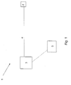
- Figure 1 shows an implantable electronic device 1 comprising an electrode 2 and a main electronic unit 3.
- the electrode 2 and the main electronic unit 3 are connected by an isolated wire 4.
- the main electronic unit 3 controls the operation of the device 1 and is adapted to generate an electric shock capable of inducing fibrillation in a mammal.
- the device 1 further comprises means for deploying an electric shock 5, which are programmable or deployable by the mammal carrying the device in his body or a duly authorized person or organisation.
- the components are basically formed in a manner used by skilled persons for implacable defibrillators.
- the means for deploying an electric shock 5 can be programmed to immediately or within a certain time frame induce an electric shock by the main electronic unit 3 over the isolated wire 4 and the electrode 2 directly into the heart of the person wearing the device.
- the means for deploying an electric shock 5 are connected to the main electronic unit 3 wirelessly by known protocols such as Bluetooth.
- the means for deploying an electric shock 5 can be coupled to a centre of decision (not shown), where physical parameters or other parameters are stored and used as decision criteria for the possibility of applying an electric shock.
- the main electronic 3 unit may further be provided with additional sensors such as sensors for measurement of inertia or sensors for measurement of acceleration.
- the main electronic unit additionally may comprise a GPS emitter and/or a GSM device for tracking the position of the mammal carrying the implantable device 1 and communication with the main electronic unit 3 wirelessly.
- the electrode 2 is configured such as being capable of measuring the heart's contractions and of deploying an electric shock.
- Figure 2 shows the preferred waveform of the electric shock deployed by main electronic unit 3 (see figure 1 ) to induce a fibrillation.
- the wave form is a sinus-wave of the energy in percent over time.
Landscapes
- Health & Medical Sciences (AREA)
- Engineering & Computer Science (AREA)
- Biomedical Technology (AREA)
- Nuclear Medicine, Radiotherapy & Molecular Imaging (AREA)
- Radiology & Medical Imaging (AREA)
- Life Sciences & Earth Sciences (AREA)
- Animal Behavior & Ethology (AREA)
- General Health & Medical Sciences (AREA)
- Public Health (AREA)
- Veterinary Medicine (AREA)
- Cardiology (AREA)
- Electrotherapy Devices (AREA)
Priority Applications (1)
| Application Number | Priority Date | Filing Date | Title |
|---|---|---|---|
| EP13305037.7A EP2754464A1 (de) | 2013-01-15 | 2013-01-15 | Implantierbare elektronische Vorrichtung |
Applications Claiming Priority (1)
| Application Number | Priority Date | Filing Date | Title |
|---|---|---|---|
| EP13305037.7A EP2754464A1 (de) | 2013-01-15 | 2013-01-15 | Implantierbare elektronische Vorrichtung |
Publications (1)
| Publication Number | Publication Date |
|---|---|
| EP2754464A1 true EP2754464A1 (de) | 2014-07-16 |
Family
ID=47710062
Family Applications (1)
| Application Number | Title | Priority Date | Filing Date |
|---|---|---|---|
| EP13305037.7A Withdrawn EP2754464A1 (de) | 2013-01-15 | 2013-01-15 | Implantierbare elektronische Vorrichtung |
Country Status (1)
| Country | Link |
|---|---|
| EP (1) | EP2754464A1 (de) |
Citations (6)
| Publication number | Priority date | Publication date | Assignee | Title |
|---|---|---|---|---|
| EP0516811A1 (de) | 1990-12-19 | 1992-12-09 | Univ Michigan State | Zusammensetzungen für euthanasie. |
| EP0773039A1 (de) | 1995-11-10 | 1997-05-14 | ELA MEDICAL (Société anonyme) | Aktive medizinische Vorrichtung, insbesondere implantierbarer Defibrillator/Kardiovertierer |
| US5643323A (en) * | 1995-06-07 | 1997-07-01 | Angeion Corporation | System and method inducing fibrillation using an implantable defibrillator |
| US5782878A (en) * | 1994-12-07 | 1998-07-21 | Heartstream, Inc. | External defibrillator with communications network link |
| DE29920843U1 (de) | 1999-11-29 | 2000-03-30 | Modler, Frank, 58091 Hagen | Vorrichtung zur Feststellung des Scheintods von bereits erdbestatteten Personen |
| US20100030288A1 (en) * | 2008-07-31 | 2010-02-04 | Medtronic, Inc. | Extravascular arrhythmia induction |
-
2013
- 2013-01-15 EP EP13305037.7A patent/EP2754464A1/de not_active Withdrawn
Patent Citations (6)
| Publication number | Priority date | Publication date | Assignee | Title |
|---|---|---|---|---|
| EP0516811A1 (de) | 1990-12-19 | 1992-12-09 | Univ Michigan State | Zusammensetzungen für euthanasie. |
| US5782878A (en) * | 1994-12-07 | 1998-07-21 | Heartstream, Inc. | External defibrillator with communications network link |
| US5643323A (en) * | 1995-06-07 | 1997-07-01 | Angeion Corporation | System and method inducing fibrillation using an implantable defibrillator |
| EP0773039A1 (de) | 1995-11-10 | 1997-05-14 | ELA MEDICAL (Société anonyme) | Aktive medizinische Vorrichtung, insbesondere implantierbarer Defibrillator/Kardiovertierer |
| DE29920843U1 (de) | 1999-11-29 | 2000-03-30 | Modler, Frank, 58091 Hagen | Vorrichtung zur Feststellung des Scheintods von bereits erdbestatteten Personen |
| US20100030288A1 (en) * | 2008-07-31 | 2010-02-04 | Medtronic, Inc. | Extravascular arrhythmia induction |
Similar Documents
| Publication | Publication Date | Title |
|---|---|---|
| CN105492069B (zh) | 具有改进的导电通信的无引线起搏器 | |
| US8554318B2 (en) | Detection of strong static magnetic fields and MRI examination safekeeping for an implantable cardiac prosthesis | |
| US9270137B2 (en) | System and method for controlling charging energy delivered to an implantable medical device | |
| US9364663B2 (en) | Detector for electromagnetic fields | |
| JP2005515857A (ja) | 埋め込み可能医療デバイス | |
| US20130190833A1 (en) | Use of Electric Fields for Reducing Patient Discomfort During Defibrillation | |
| US10130822B2 (en) | System and method for protecting against magnetic fields produced by MRI | |
| US20100057153A1 (en) | Electromagnetic interference alarm | |
| US9867983B2 (en) | Active implantable device suitable for use in an MRI scanner | |
| US20170173345A1 (en) | Multi-Tiered Wireless Powering System for Long-Term Implantable Medical Devices | |
| EP2257337B1 (de) | Atriale defibrillation mit einem implantierbaren defibrillationssystem | |
| Senthuran et al. | Editorial III: implanted cardiac pacemakers and defibrillators in anaesthetic practice | |
| US8558514B2 (en) | Detector for electromagnetic fields | |
| US20040210256A1 (en) | Methods and apparatus for decreasing incidences of early recurrence of atrial fibrillation | |
| CN110709131B (zh) | 具有用于将功率发射到另一植入式医疗设备的栓系式发射线圈的植入式医疗设备 | |
| EP2754464A1 (de) | Implantierbare elektronische Vorrichtung | |
| EP4048394B1 (de) | Implantierbare medizinische vorrichtung | |
| US20160144193A1 (en) | Medical implant with a communications interface | |
| US7769453B2 (en) | Implantable battery-operated electrostimulation device | |
| US20130150909A1 (en) | Modes of operation for atrial defibrillation using an implantable defibrillator | |
| US12582828B2 (en) | Pacing device and method of operation thereof | |
| US8649877B2 (en) | Extended noise mode | |
| Bhatia et al. | Electromagnetic Interference: Sources, Recognition, and Management |
Legal Events
| Date | Code | Title | Description |
|---|---|---|---|
| PUAI | Public reference made under article 153(3) epc to a published international application that has entered the european phase |
Free format text: ORIGINAL CODE: 0009012 |
|
| 17P | Request for examination filed |
Effective date: 20130115 |
|
| AK | Designated contracting states |
Kind code of ref document: A1 Designated state(s): AL AT BE BG CH CY CZ DE DK EE ES FI FR GB GR HR HU IE IS IT LI LT LU LV MC MK MT NL NO PL PT RO RS SE SI SK SM TR |
|
| AX | Request for extension of the european patent |
Extension state: BA ME |
|
| STAA | Information on the status of an ep patent application or granted ep patent |
Free format text: STATUS: THE APPLICATION IS DEEMED TO BE WITHDRAWN |
|
| 18D | Application deemed to be withdrawn |
Effective date: 20150117 |