EP2754536A2 - Système de moteur pour dispositifs à double tension - Google Patents
Système de moteur pour dispositifs à double tension Download PDFInfo
- Publication number
- EP2754536A2 EP2754536A2 EP13196109.6A EP13196109A EP2754536A2 EP 2754536 A2 EP2754536 A2 EP 2754536A2 EP 13196109 A EP13196109 A EP 13196109A EP 2754536 A2 EP2754536 A2 EP 2754536A2
- Authority
- EP
- European Patent Office
- Prior art keywords
- motor
- power
- battery
- rotation
- mode
- Prior art date
- Legal status (The legal status is an assumption and is not a legal conclusion. Google has not performed a legal analysis and makes no representation as to the accuracy of the status listed.)
- Granted
Links
Images



Classifications
-
- B—PERFORMING OPERATIONS; TRANSPORTING
- B25—HAND TOOLS; PORTABLE POWER-DRIVEN TOOLS; MANIPULATORS
- B25F—COMBINATION OR MULTI-PURPOSE TOOLS NOT OTHERWISE PROVIDED FOR; DETAILS OR COMPONENTS OF PORTABLE POWER-DRIVEN TOOLS NOT PARTICULARLY RELATED TO THE OPERATIONS PERFORMED AND NOT OTHERWISE PROVIDED FOR
- B25F5/00—Details or components of portable power-driven tools not particularly related to the operations performed and not otherwise provided for
- B25F5/001—Gearings, speed selectors, clutches or the like specially adapted for rotary tools
-
- H—ELECTRICITY
- H02—GENERATION; CONVERSION OR DISTRIBUTION OF ELECTRIC POWER
- H02K—DYNAMO-ELECTRIC MACHINES
- H02K7/00—Arrangements for handling mechanical energy structurally associated with dynamo-electric machines, e.g. structural association with mechanical driving motors or auxiliary dynamo-electric machines
- H02K7/14—Structural association with mechanical loads, e.g. with hand-held machine tools or fans
-
- A—HUMAN NECESSITIES
- A01—AGRICULTURE; FORESTRY; ANIMAL HUSBANDRY; HUNTING; TRAPPING; FISHING
- A01D—HARVESTING; MOWING
- A01D34/00—Mowers; Mowing apparatus of harvesters
- A01D34/01—Mowers; Mowing apparatus of harvesters characterised by features relating to the type of cutting apparatus
- A01D34/412—Mowers; Mowing apparatus of harvesters characterised by features relating to the type of cutting apparatus having rotating cutters
- A01D34/416—Flexible line cutters
-
- B—PERFORMING OPERATIONS; TRANSPORTING
- B25—HAND TOOLS; PORTABLE POWER-DRIVEN TOOLS; MANIPULATORS
- B25F—COMBINATION OR MULTI-PURPOSE TOOLS NOT OTHERWISE PROVIDED FOR; DETAILS OR COMPONENTS OF PORTABLE POWER-DRIVEN TOOLS NOT PARTICULARLY RELATED TO THE OPERATIONS PERFORMED AND NOT OTHERWISE PROVIDED FOR
- B25F5/00—Details or components of portable power-driven tools not particularly related to the operations performed and not otherwise provided for
-
- H—ELECTRICITY
- H02—GENERATION; CONVERSION OR DISTRIBUTION OF ELECTRIC POWER
- H02K—DYNAMO-ELECTRIC MACHINES
- H02K11/00—Structural association of dynamo-electric machines with electric components or with devices for shielding, monitoring or protection
- H02K11/20—Structural association of dynamo-electric machines with electric components or with devices for shielding, monitoring or protection for measuring, monitoring, testing, protecting or switching
-
- H—ELECTRICITY
- H02—GENERATION; CONVERSION OR DISTRIBUTION OF ELECTRIC POWER
- H02K—DYNAMO-ELECTRIC MACHINES
- H02K7/00—Arrangements for handling mechanical energy structurally associated with dynamo-electric machines, e.g. structural association with mechanical driving motors or auxiliary dynamo-electric machines
- H02K7/10—Structural association with clutches, brakes, gears, pulleys or mechanical starters
- H02K7/108—Structural association with clutches, brakes, gears, pulleys or mechanical starters with friction clutches
-
- H—ELECTRICITY
- H02—GENERATION; CONVERSION OR DISTRIBUTION OF ELECTRIC POWER
- H02K—DYNAMO-ELECTRIC MACHINES
- H02K7/00—Arrangements for handling mechanical energy structurally associated with dynamo-electric machines, e.g. structural association with mechanical driving motors or auxiliary dynamo-electric machines
- H02K7/20—Structural association with auxiliary dynamo-electric machines, e.g. with electric starter motors or exciters
-
- H—ELECTRICITY
- H02—GENERATION; CONVERSION OR DISTRIBUTION OF ELECTRIC POWER
- H02K—DYNAMO-ELECTRIC MACHINES
- H02K23/00—DC commutator motors or generators having mechanical commutator; Universal AC/DC commutator motors
Definitions
- the invention relates to power tools, and more particularly to dual-voltage power tools. It is often desirable for power tools, small appliances, and other devices that include an electric motor to have the option to operate either with a battery or connected to an electrical outlet. These "corded/cordless" products are attractive because they do not have the limitations of a single power source. A corded tool for example, is not portable and cannot be used in places where electrical outlets are not available. On the other hand, a cordless tool has a limited runtime and may have lower performance than a corded device.
- the invention provides, in one aspect, a power tool including a housing and an output shaft supported by the housing for rotation about an axis.
- the power tool further includes a first motor disposed in the housing and a second motor disposed in the housing and coupled to the first motor.
- the first motor drives the output shaft and does not drive the second motor when in a first power mode
- the second motor drives the first motor and the output shaft when in a second power mode.
- the invention also provides, in another aspect, a power tool including a housing and a tool element supported by the housing for rotation about an axis.
- the power tool also includes a first motor rotationally coupled to the tool element and operable in response to a DC power supply to rotate the tool element.
- a second motor is selectively rotationally coupled to the first motor and the tool element and operable in response to an AC power supply to rotate the first motor and the tool element.
- the power tool further includes a coupling mechanism disposed between the second motor and the first motor. The coupling mechanism is operable in a first mode to decouple the rotation of the first motor and the second motor when DC power is supplied to the first motor, and operable in a second mode to couple the rotation of the first motor and the second motor when AC power is supplied to the second motor.
- the invention further provides, in another aspect, a power tool including a housing and an output shaft supported by the housing for rotation about an axis.
- the power tool also includes a battery terminal selectively operable to receive a DC power supply from a battery and a receptacle selectively operable to receive an AC power supply from an AC power source.
- the power tool further includes a motor.
- the motor is operable in a first power mode, in response to receipt of the DC power supply, to rotatably drive the output shaft.
- the motor is also operable in a second power mode, in response to receipt of the AC power supply, to rotatably drive the output shaft.
- the power tool also includes a mechanical interlock movable between a first position in which the interlock inhibits the flow of the AC power supply to the motor and a second position in which the interlock inhibits the flow of the DC power supply to the motor.
- FIG. 1 illustrates a power tool according to an embodiment of the invention.
- the invention is embodied in a string trimmer 10; however, the features of the invention described herein are equally applicable to other types of power tools and electric appliances.
- the string trimmer 10 includes a shaft 14 having a rear handle 18 at its upper end and a forward handle 22 spaced from the rear handle 18 to facilitate two-handed operation of the string trimmer 10.
- the forward handle 22 includes a flange 26 operable to permit adjustment of the position of the forward handle 22 on the shaft 14 and/or the orientation of the forward handle 22 relative to the shaft 14. In other embodiments, the forward handle 22 may be fixed to the shaft 14 or integrally formed as a part of the shaft 14.
- the shaft 14 comprises an upper tube 30 and a lower tube 34 in a telescoping arrangement.
- a locking mechanism 38 is disposed on an intermediate portion of the shaft 14, circumscribing the interface between the upper and lower tubes 30, 34.
- the locking mechanism 38 is rotatable in a first direction to permit telescopic movement of the upper tube 30 and the lower tube 34, thereby permitting extension or contraction of the shaft 14.
- the locking mechanism 38 is rotatable in an opposite direction to inhibit telescopic movement of the upper tube 30 and the lower tube 34, thereby locking the shaft 14 at a particular length.
- the locking mechanism 38 is configured as a collar; however, the locking mechanism 38 may take any form, such as a cam lever or a notch and detent system.
- the shaft 14 may be formed as a single piece and may not be adjustable.
- the string trimmer 10 includes a head portion 42 that includes a housing 46 and a string hub 50 disposed on the underside of the housing and defining an axis 54 ( FIG. 1 ).
- the string hub 50 may include an internal bobbin or spool (not shown) and may be configured for bump-feed, fixed line, or automatic-feed operation. Alternatively, the string hub 50 may have any other suitable configuration.
- a length of flexible line extends radially outward from the string hub 50 to form a cutting element 58.
- a cowl 62 partially surrounds a lower periphery of the housing 46 to shield an operator of the string trimmer 10 from the cutting element 58 and any debris produced during operation.
- the head portion 46 includes a first motor 66 supported by the housing 46 and aligned with the axis 54 of the string hub 50.
- the first motor 66 has an output shaft 70 that extends through both ends of the motor 66 and that is coupled to the string hub 50 to transmit torque to the string hub 50 ( FIG. 3 ).
- the first motor 66 is a direct current (DC) motor, such as a brushed or brushless permanent-magnet DC motor.
- the first motor 66 is configured to receive power from a rechargeable battery 74 (e.g., lithium-ion, nickel-metal hydride, nickel-cadmium, etc.) ( FIG. 2 ).
- a rechargeable battery 74 e.g., lithium-ion, nickel-metal hydride, nickel-cadmium, etc.
- the head portion 42 also includes a second motor 78 supported by the housing 46 and arranged coaxially with the first motor 66.
- the second motor 78 may be offset from the first motor 66 and/or oriented at an angle relative to the axis 54.
- some constructions may include one or both of the first motor 66 and the second motor 78 that is arranged in an offset position with respect to the axis 54 or that are arranged at an oblique angle with respect to the axis 54.
- the second motor 78 is an alternating current (AC) motor, such as a universal AC motor or an AC induction motor.
- the second motor 78 is configured to receive power from a high-voltage, AC power source 82, such as a conventional wall outlet.
- the second motor 78 may be a DC motor and the string trimmer 10 may include a rectifier circuit (not shown) to convert AC power from the high-voltage power source 82 to DC power usable by the second motor 78.
- the second motor 78 includes an output shaft 86 selectively coupled for rotation to the output shaft 70 of the first motor 66 via a coupling member 90.
- the coupling member 90 may be any structure operable to selectively couple the output shaft 86 of the second motor 78 to the output shaft 70 of the first motor 66, such as a friction clutch, a centrifugal clutch, a roller clutch, and the like. Specific embodiments of the coupling member 90 are described in detail herein.
- the string trimmer 10 is capable of operating in a first power mode (i.e., a cordless mode) in which the first motor 66 draws power from the battery 74.
- a first power mode i.e., a cordless mode
- the coupling member 90 permits relative rotation between the output shaft 70 of the first motor 66 and the output shaft 86 of the second motor 78, decoupling the first motor 66 from any rotational drag associated with the second motor 78. Accordingly, in the first power mode, the first motor 66 need only produce enough torque to drive the string hub 50 at a suitable working speed.
- the string trimmer 10 is also capable of operating in a second power mode (i.e., a corded mode) in which the second motor 78 draws power from the AC power source 82 through a power cable 84.
- a second power mode i.e., a corded mode
- the coupling member 90 couples the output shaft 86 of the second motor 78 with the output shaft 70 of the first motor 66 for rotation.
- the second motor 78 drives the string hub 50 through the first motor 66. Accordingly, to overcome the added rotational drag of the first motor 66, the second motor 78 must produce more torque than the first motor 66 produces in the first power mode in order to drive the string hub 50 at the suitable working speed.
- the string trimmer 10 includes a battery charging circuit 94 operable to recharge the battery 74 when the string trimmer 10 is operated in the second power mode ( FIG. 2 ). Because the output shaft 70 of the first motor 66 is rotated by the second motor 78 in the second power mode, the first motor 66 may act as a DC power supply (i.e., a generator) to supply a charging current to the battery 74. In other embodiments, the first motor 66 may not act as a DC power supply, and a rectifier circuit (not shown) may be included to recharge the battery 74 directly from the AC power supply 82. In still other embodiments, the string trimmer 10 may not include any battery charging circuitry 94, and the battery 72 may be recharged using an external charging apparatus (not shown).
- a battery charging circuit 94 operable to recharge the battery 74 when the string trimmer 10 is operated in the second power mode ( FIG. 2 ). Because the output shaft 70 of the first motor 66 is rotated by the second motor 78 in the second power mode, the first motor
- the coupling member 90 takes the form of a clutch mechanism 98 including a driving member 102 and a driven member 106.
- the driven member 106 is fixed to the output shaft 70 of the first motor 66 (e.g., by a press-fit, key, snap ring, pin, etc.) such that rotation of the driven member 106 corresponds with rotation of the output shaft 70 and, therefore, with rotation of the string hub 50.
- the driven member 106 includes a plurality of recesses 110 shaped to receive a corresponding plurality of teeth 114 projecting from an axial surface of the driving member 102.
- the clutch mechanism 98 includes an externally-threaded tube 122, (referred to herein as a lead screw 122), that is fixed to the output shaft 86 of the second motor 78 by any suitable means (e.g., press-fit, key, snap ring, pin, etc.).
- the driving member 102 includes internal threads 126 corresponding to the external threads of the lead screw 122 such that relative rotation between the lead screw 122 and the driving member 102 translates the driving member 102 along the axis 54. Translation of the driving member 102 toward a disengaged position of the clutch mechanism 98 is bounded by a shoulder 130 of the second motor 78. Translation of the driving member 102 toward an engaged position of the clutch mechanism 98 is bounded by the driven member 106.
- the clutch mechanism also includes a washer 134 secured to the output shaft 86 by a retaining ring 138 (e.g., a snap ring).
- a biasing member 142 is constrained between the washer 134 and the driving member 102 to bias the driving member 102 towards the disengaged position of the clutch mechanism 98.
- FIGS. 3 and 4 illustrate the disengaged and the engaged positions of the clutch mechanism 98, respectively.
- the teeth 114 are engaged with the recesses 110 to couple the driving member 102 and the driven member 106 for rotation.
- the driving member 102 is axially spaced from the driven member 106, decoupling the first and second motors 66, 78 such that relative rotation between the driving member 102 and the driven member 106 is permitted.
- FIG. 6 illustrates an alternative embodiment of the coupling member 90.
- the coupling member 90 takes the form of a one-way bearing 146 (i.e., a roller clutch).
- the one-way bearing 146 includes an outer race 150 coupled to the output shaft 86 of the second motor 78, and an inner race (not shown) coupled to the output shaft 70 of the first motor 66.
- the output shafts 70, 86 may be coupled to the one-way bearing 146 in any suitable manner, such as with cooperating splines, a press-fit, a key and keyway, conventional fasteners, and the like.
- the outer race 150 may be coupled to the output shaft 70 of the first motor 66
- the inner race may be coupled to the output shaft 86 of the second motor 78.
- a plurality of rollers is disposed in angled channels (not shown) between the inner race and the outer race 150.
- the rollers and channels are configured such that the inner race may slip relative to the outer race 150 in a first direction (e.g., clockwise), but the rollers bind the inner race and the outer race 150 in a second direction (e.g., counterclockwise).
- the selective slipping/binding of the one-way bearing 146 couples the output shaft 86 of the second motor 78 with the output shaft 70 of the first motor 66 for rotation in the first direction and allows relative rotation between the two output shafts 70, 86 in the second direction.
- a user may desire to operate the string trimmer 10 in the first power mode (i.e., the cordless mode) when no power outlets are conveniently available.
- the first motor 66 draws DC power from the battery 74 in order to provide torque to the string hub 50 and rotate the cutting element 58 at a sufficient speed to cut down grass or other vegetation.
- the coupling member 90 permits relative rotation between the output shaft 70 of the first motor 66 and the output shaft 86 of the second motor 78, decoupling the first motor 66 from any resistance associated with the second motor 78 and optimizing battery life.
- the user may desire to operate the string trimmer 10 in the second power mode (i.e., the corded mode).
- the second motor 78 draws power from the AC power source 82, and the coupling member 90 couples the output shaft 86 of the second motor 78 with the output shaft 70 of the first motor 66 for rotation.
- the second motor 78 provides torque to the string hub 50 through the coupling member 90 and the output shaft 70 of the first motor 66.
- the first motor 66 may act as a DC power supply, to generate power through the battery charging circuit 94 in order to recharge the battery 74.
- FIG. 7 illustrates a string trimmer 1010 according to another embodiment of the invention.
- This embodiment employs much of the same structure as the embodiments of the string trimmer 10 described above in connection with FIGS. 1-6 . Accordingly, the following description focuses primarily upon the structure and features that are different than the embodiments described above in connection with FIGS. 1-6 . Reference should be made to the description above in connection with FIGS. 1-6 for additional information regarding the structure and features, and possible alternatives to the structure and features of the string trimmer 1010 illustrated in FIG. 7 and described below. Structure and features of the embodiment shown in FIG. 7 that correspond to structure and features of the embodiments of FIGS. 1-6 are designated hereinafter in the 1000 series of reference numbers.
- the string trimmer 1010 includes a shaft 1014 having a rear handle 1018 at its upper end and a forward handle 1022 spaced from the rear handle 1018 to facilitate two-handed operation of the string trimmer 1010.
- the string trimmer 1010 includes a head portion 1042 that includes a housing 1046 and a string hub 1050 disposed on the underside of the housing and defining an axis 1054 ( FIG. 7 ).
- a length of flexible line extends radially outward from the string hub 1050 to form a cutting element 1058.
- the head portion 1042 includes a motor 1154 supported by the housing 1046 and aligned with the axis 1054 of the string hub 1050.
- the motor 1154 has an output shaft 1158 that is coupled to the string hub 1050 to transmit torque to the string hub 1050.
- the motor 1154 is configured as a dual-commutator motor, including a DC commutator (not shown) associated with a DC armature (not shown), and a rectified AC commutator (not shown) associated with an AC armature (not shown).
- the motor 1154 is able to selectively receive power from a rechargeable battery 1074 or from a high-voltage, AC power source 1082, such as a conventional wall outlet.
- the string trimmer 1010 could employ the two-motor arrangement of the string trimmer 10 of Figs. 1-6 if desired.
- the string trimmer 10 could employ the motor 1154 of the string trimmer 1010 of Figs. 7-13 .
- the string trimmer 1010 is capable of operating in a first power mode (i.e., a cordless mode) in which the motor 1154 draws power from the battery 1074.
- a first power mode i.e., a cordless mode
- the rear handle 1018 of the string trimmer 1010 includes a battery terminal 1162 disposed within a battery receiving portion 1166 of the rear handle 1018.
- the battery 1074 is electrically connected to the battery terminal 1162 when the string trimmer 1010 is operated in the first power mode.
- the string trimmer 1010 is also capable of operating in a second power mode (i.e., a corded mode) in which the motor 1154 draws power from the AC power source 1082 through a power cable 1084.
- the rear handle 1018 includes a receptacle 1170 for receiving the power cable 1084.
- the power cable 1084 (and the AC power source 1082) is electrically connected to the receptacle when the string trimmer 1010 is operated in the second power mode.
- FIG. 9 illustrates a wiring diagram for the motor 1154.
- the motor 1154 includes high voltage terminals 1174a, 1174b electrically connected to a first set of brushes (not shown) associated with the rectified AC commutator.
- the motor 1154 also includes low voltage terminals 1178a, 1178b electrically connected to a second set of brushes (not shown) associated with the DC commutator.
- a first power circuit 1182 electrically connects live and neutral poles 1186a, 1186b of the receptacle 1170 to the high voltage terminals 1174a, 1174b of the motor 1154 through a full-bridge rectifier 1190.
- the rectifier 1190 converts AC current supplied by the AC power source 1082 into a DC ripple current.
- a power conditioner (e.g., a capacitor; not shown) may be included to attenuate the amplitude of the ripple.
- a second power circuit 1194 electrically connects positive and negative poles 1198a, 1198b of the battery terminal 1162 to the low voltage terminals 1178a, 1178b of the motor 1154.
- the second power circuit 1194 may include a pair of diodes 1202a, 1202b configured to protect the battery 1074 from any backflow current.
- the first power circuit 1182 includes a first switch 1206 movable between a first position (i.e., a closed position) connecting the live pole 1186a to the power circuit 1182 and a second position (i.e., an open position) disconnecting the live pole 1186a from the power circuit 1182.
- the first switch 1206 is configured as a normally open switch and moves to the closed position in response to the AC power source 1082 being connected to the receptacle 1170.
- the second power circuit 1194 includes a second switch 1210 movable between a first position (i.e., a closed position) connecting the positive pole 1198a to the power circuit 1194 and a second position (i.e., an open position) disconnecting the positive pole 1198a from the power circuit 1194.
- the second switch 1210 is configured as a normally open switch and moves to the closed position in response to the battery 1074 being connected to the battery terminal 1162.
- the first switch 1206 and the second switch 1210 are synchronized, such that the position of the first switch 1206 corresponds with the position of the second switch 1210.
- an electrical connection between either the AC power source 1082 and the receptacle 1170 or the battery 1074 and the battery terminal 1162 triggers both the first switch 1206 and the second switch 1210 to move to the closed position.
- the switches 1206, 1210 are connected to a trigger or other user actuated mechanism such that power can only be delivered when the user actuates the trigger or other mechanism.
- the user's actuation of the trigger or other mechanism closes both switches 1206, 1210 while the release of the trigger opens the switches 1206, 1210.
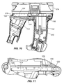
- the rear handle 1018 includes a mechanical interlock 1214 movable between a first position ( FIG. 10 ) in which the interlock 1214 physically blocks access to the receptacle 1170 and a second position ( FIG. 12 ) in which the interlock 1214 physically blocks access to the battery terminal 1162.
- the interlock 1214 allows only one of the battery 1074 and the AC power source 1082 to be connected to the string trimmer 1010 at any given time. Accordingly, the string trimmer 1010 is operable in the cordless mode only when the interlock 1214 is in the first position and in the corded mode only when the interlock 1214 is in the second position.
- the interlock 1214 may be configured as an electrical interlock, such as a switch.
- the interlock 1214 is configured as a generally flat door, slidable within a track 1218 formed in the rear handle 1018.
- a first detent 1222 ( FIG. 11 ) and a second detent 1226 ( FIG. 13 ) project from the track 1218 in positions corresponding with the first and second positions of the interlock 1214, respectively.
- a third detent 1230 projects from a surface 1234 of the interlock 1214 and is configured to engage with the first detent 1222 when the interlock 1214 is in the first position and to engage with the second detent 1226 when the interlock 1214 is in the second position.
- Interference between the third detent 1230 and the first detent 1222 provides tactile feedback that the interlock 1214 has reached the first position and inhibits the interlock 1214 from inadvertently moving out of the first position.
- interference between the third detent 1230 and the second detent 1226 provides tactile feedback that the interlock 1214 has reached the second position and inhibits the interlock 1214 from inadvertently moving out of the second position.
- any number or configuration of detents may be used. Still other embodiments may not include any detents.
- a plurality of raised ribs 1238 extends from the surface 1234 of the interlock 1214 to facilitate manipulation of the interlock 1214 between the first and second positions.
- a handle, lever, or button may be included to manipulate the interlock 1214 between the first and second positions.
- the interlock 1214 may be automatically movable between the first and second positions in response to insertion or removal of the battery 1074 and/or the power cord 1084.
- a user may desire to operate the string trimmer 1010 in the first power mode (i.e., the cordless mode) when no power outlets are conveniently available.
- the user first positions the mechanical interlock 1214 in the first position to permit an electrical connection between the battery 1074 and the battery terminal 1162.
- the first and second switches 1206, 1210 move to the closed position, electrically connecting the battery 1074 to the motor 1154.
- the motor 1154 draws DC power from the battery 1074 in order to provide torque to the string hub 1050 and rotate the cutting element 1058 at a sufficient speed to cut down grass or other vegetation.
- the user may desire to operate the string trimmer 1010 in the second power mode (i.e., the corded mode).
- the user disconnects the battery 1074 from the string trimmer 1010, and the first and second switches 1206, 1210 move to the open position.
- the user positions the mechanical interlock 1214 in the second position to permit access to the receptacle 1170.
- the user plugs the power cable 1084 into the receptacle 1170 to provide an electrical connection between the AC power source 1082 and the receptacle 1170.
- the first and second switches 1206, 1210 move to the closed position, electrically connecting the AC power source 1082 to the motor 1154.
- the motor 1154 draws power from the AC power source 1082 in order to provide torque to the string hub 1050 and rotate the cutting element 1058 at a sufficient speed to cut down grass or other vegetation.
- string trimmers 10 and 1010 described herein are equally applicable to other types of power tools and electric appliances, such as drills, saws, routers, sanders, blowers, vacuums, portable lights, and the like.
- aspects of the string trimmers 10, 1010 described with regard to one of the string trimmers 10, 1010 are equally applicable to the other string trimmer 10, 1010.
Landscapes
- Engineering & Computer Science (AREA)
- Power Engineering (AREA)
- Mechanical Engineering (AREA)
- Life Sciences & Earth Sciences (AREA)
- Environmental Sciences (AREA)
- Microelectronics & Electronic Packaging (AREA)
- Harvester Elements (AREA)
- Constituent Portions Of Griding Lathes, Driving, Sensing And Control (AREA)
- Finish Polishing, Edge Sharpening, And Grinding By Specific Grinding Devices (AREA)
- Connection Of Motors, Electrical Generators, Mechanical Devices, And The Like (AREA)
Applications Claiming Priority (1)
| Application Number | Priority Date | Filing Date | Title |
|---|---|---|---|
| US13/736,415 US9427859B2 (en) | 2013-01-08 | 2013-01-08 | Motor system for dual voltage devices |
Publications (3)
| Publication Number | Publication Date |
|---|---|
| EP2754536A2 true EP2754536A2 (fr) | 2014-07-16 |
| EP2754536A3 EP2754536A3 (fr) | 2015-09-16 |
| EP2754536B1 EP2754536B1 (fr) | 2020-12-02 |
Family
ID=49884900
Family Applications (1)
| Application Number | Title | Priority Date | Filing Date |
|---|---|---|---|
| EP13196109.6A Active EP2754536B1 (fr) | 2013-01-08 | 2013-12-06 | Système de moteur pour dispositifs à double tension |
Country Status (6)
| Country | Link |
|---|---|
| US (1) | US9427859B2 (fr) |
| EP (1) | EP2754536B1 (fr) |
| CN (2) | CN107276308B (fr) |
| AU (2) | AU2013267076B2 (fr) |
| CA (1) | CA2838389C (fr) |
| MX (1) | MX369565B (fr) |
Cited By (1)
| Publication number | Priority date | Publication date | Assignee | Title |
|---|---|---|---|---|
| EP3135092A1 (fr) * | 2015-08-27 | 2017-03-01 | AC (Macao Commerical Offshore) Limited | Outil de puissance amélioré et mécanisme de transmission de rotation pour un outil électrique |
Families Citing this family (50)
| Publication number | Priority date | Publication date | Assignee | Title |
|---|---|---|---|---|
| WO2008048615A2 (fr) * | 2006-10-17 | 2008-04-24 | Desa Ip, Llc | Dispositif électrique hybride |
| EP2110921B1 (fr) | 2008-04-14 | 2013-06-19 | Stanley Black & Decker, Inc. | Système de gestion de batterie pour outil sans fil |
| WO2013032373A1 (fr) * | 2011-08-26 | 2013-03-07 | Husqvarna Ab | Outil de coupe portatif alimenté par batterie |
| US9956677B2 (en) * | 2013-05-08 | 2018-05-01 | Black & Decker Inc. | Power tool with interchangeable power heads |
| US9472992B2 (en) * | 2013-07-11 | 2016-10-18 | The Toro Company | Electric motor support structure and power equipment unit incorporating same |
| US9762153B2 (en) * | 2013-10-18 | 2017-09-12 | Black & Decker Inc. | Cycle-by-cycle current limit for power tools having a brushless motor |
| CN108400629B (zh) | 2014-05-18 | 2023-01-24 | 百得有限公司 | 电池组 |
| US9893384B2 (en) | 2014-05-18 | 2018-02-13 | Black & Decker Inc. | Transport system for convertible battery pack |
| CN105471146A (zh) | 2014-09-04 | 2016-04-06 | 苏州宝时得电动工具有限公司 | 电动工具 |
| US20160088792A1 (en) * | 2014-09-28 | 2016-03-31 | Chervon Intellectual Property Limited | Grass trimmer |
| US10285698B2 (en) | 2015-02-26 | 2019-05-14 | Covidien Lp | Surgical apparatus |
| CN104798542B (zh) * | 2015-03-24 | 2016-11-30 | 浙江亚特电器有限公司 | 一种双动力割草机 |
| CN106134617A (zh) * | 2015-03-25 | 2016-11-23 | 南京德朔实业有限公司 | 打草机 |
| US10433487B2 (en) * | 2015-04-21 | 2019-10-08 | Aero-Flex Technologies, Inc. | Walk-behind mower/trimmer with 360 degree maneuverability |
| WO2017107050A1 (fr) * | 2015-12-22 | 2017-06-29 | Ac (Macao Commercial Offshore) Limited | Fixation pour outil électrique, outil électrique et procédé de fonctionnement d'un outil électrique |
| US12557730B2 (en) | 2016-01-22 | 2026-02-24 | Nanjing Chervon Industry Co., Ltd. | Grass trimmer |
| US10440882B2 (en) * | 2016-01-22 | 2019-10-15 | Nanjing Chervon Industry Co., Ltd. | Grass trimmer, operating method thereof and control method thereof |
| CN106993426B (zh) | 2016-01-22 | 2019-03-08 | 南京德朔实业有限公司 | 打草机 |
| US11818979B2 (en) | 2016-01-22 | 2023-11-21 | Nanjing Chervon Industry Co., Ltd. | Grass trimmer |
| DE102016106557A1 (de) * | 2016-04-11 | 2017-10-12 | Festool Gmbh | Hand-Werkzeugmaschine mit einem Antriebsmotor |
| TWI598035B (zh) * | 2016-08-04 | 2017-09-11 | Clutch casing of the portable lawn mower combined with the operating rod | |
| US20180056496A1 (en) * | 2016-08-26 | 2018-03-01 | Robert Bosch Tool Corporation | Modular Handheld Power Tool |
| EP3525570B1 (fr) * | 2016-10-14 | 2022-04-27 | Techtronic Outdoor Products Technology Limited | Taille-bordure |
| DE112017006072T5 (de) * | 2016-11-30 | 2019-08-22 | Ridge Tool Company | Hybridantriebwerkzeuge |
| WO2018119256A1 (fr) | 2016-12-23 | 2018-06-28 | Black & Decker Inc. | Système d'outil électrique sans fil |
| US20180220582A1 (en) * | 2017-02-08 | 2018-08-09 | Fred Trombino | Disposable quick-connect cutter head assembly for a rotary trimmer |
| USD858228S1 (en) * | 2017-03-30 | 2019-09-03 | Husqvarna Ab | Trimmer |
| US10688647B2 (en) * | 2017-05-19 | 2020-06-23 | The Toro Company | Lawn and garden tool with boom having adjustable length and detachable boom sections |
| USD867833S1 (en) * | 2017-10-18 | 2019-11-26 | Changzhou Globe Co., Ltd. | String trimmer head |
| EP3773068A1 (fr) * | 2018-03-27 | 2021-02-17 | Alfred Kärcher SE & Co. KG | Outil pour une machine d'élimination des mauvaises herbes et machine d'élimination des mauvaises herbes |
| WO2020181348A1 (fr) * | 2019-03-12 | 2020-09-17 | Silva Jose Carlos Da | Dispositif convertisseur électronique automatique de courant alternatif bivolt, alimentation 110 v, 127 v ou 220 v et sortie 127 v, pour moteurs universels à balais pouvant atteindre 3000 w et charges résistives pouvant atteindre 3000 w avec gradateur |
| CN111262390A (zh) * | 2020-02-25 | 2020-06-09 | 苏州小科清洁科技有限公司 | 一种动力供给单元 |
| CN111941337A (zh) * | 2020-07-15 | 2020-11-17 | 国网浙江余姚市供电有限公司 | 带有离合的远程扳手 |
| CN111785547A (zh) * | 2020-08-03 | 2020-10-16 | 上海拜骋电器有限公司 | 电动工具用直流开关组件及电动工具 |
| AU2021104983A4 (en) | 2020-09-10 | 2021-09-30 | Techtronic Cordless Gp | Blade replacement mechanism of electric instrument |
| US12202155B2 (en) | 2020-09-10 | 2025-01-21 | Techtronic Cordless Gp | Blade change mechanism for power tool |
| CN213960795U (zh) * | 2020-12-22 | 2021-08-17 | 格力博(江苏)股份有限公司 | 一种操作杆组件以及打草机 |
| CN113455172B (zh) * | 2021-06-18 | 2023-05-05 | 内江职业技术学院 | 生态农林用高效除草装置 |
| USD988101S1 (en) * | 2021-07-01 | 2023-06-06 | Huajie Dong | Handheld lawn mower |
| US12134178B2 (en) * | 2022-01-28 | 2024-11-05 | Nanjing Chervon Industry Co., Ltd. | Power tool |
| US20240399609A1 (en) * | 2022-01-28 | 2024-12-05 | Nanjing Chervon Industry Co., Ltd. | Router |
| US20230302620A1 (en) * | 2022-03-28 | 2023-09-28 | Milwaukee Electric Tool Corporation | Rotary power tool |
| CN120244076B (zh) * | 2023-12-25 | 2026-03-13 | 南京泉峰科技有限公司 | 电动工具及其控制方法 |
| CN119589019A (zh) * | 2023-09-01 | 2025-03-11 | 南京泉峰科技有限公司 | 圆锯 |
| CN120262963A (zh) * | 2023-12-25 | 2025-07-04 | 南京泉峰科技有限公司 | 电动工具及其控制方法 |
| AU2024335386A1 (en) * | 2023-09-01 | 2025-04-10 | Nanjing Chervon Industry Co., Ltd. | Power tool, cutting tool, circular saw, and control method for power tool |
| DE102023210533A1 (de) * | 2023-10-25 | 2025-04-30 | Robert Bosch Gesellschaft mit beschränkter Haftung | Handwerkzeugmaschine und Verfahren zu einem Betrieb einer Handwerkzeugmaschine |
| USD1116659S1 (en) * | 2024-03-26 | 2026-03-10 | Westinghouse Electric & Manufacturing Company | String trimmer |
| CN223251576U (zh) * | 2024-09-24 | 2025-08-22 | 永康市一顺工具有限公司 | 一种电动工具的工具头锁扣结构 |
| CN121104599B (zh) * | 2025-09-07 | 2026-04-07 | 浙江星杰汽车零部件有限公司 | 一种汽车轮毂轴承密封圈自动化压装设备 |
Family Cites Families (33)
| Publication number | Priority date | Publication date | Assignee | Title |
|---|---|---|---|---|
| US1942295A (en) | 1933-03-01 | 1934-01-02 | Westinghouse Electric & Mfg Co | Reversible-cycle heating and cooling system |
| US2433390A (en) | 1944-11-16 | 1947-12-30 | Westinghouse Electric Corp | Motor-generator |
| US2852706A (en) * | 1956-07-10 | 1958-09-16 | Philco Corp | Switching apparatus |
| US3525912A (en) * | 1966-03-28 | 1970-08-25 | Scovill Manufacturing Co | Selectable power source for a motor driven appliance |
| US3943423A (en) | 1973-08-28 | 1976-03-09 | Hoffman Philip A | Battery charging circuit |
| US4152882A (en) * | 1976-09-03 | 1979-05-08 | Howard Tyson W | Vegetation cutting assembly |
| US4333302A (en) | 1981-03-13 | 1982-06-08 | Ronald Thomas | Combined A.C./D.C. electric lawn mower |
| US4835410A (en) | 1988-02-26 | 1989-05-30 | Black & Decker Inc. | Dual-mode corded/cordless system for power-operated devices |
| US4835409A (en) | 1988-02-26 | 1989-05-30 | Black & Decker Inc. | Corded/cordless dual-mode power-operated device |
| US5160879A (en) * | 1991-10-08 | 1992-11-03 | Curtis Manufacturing Company, Inc. | Safe, rechargeable, battery-containing power pack and method |
| US5301494A (en) * | 1992-07-24 | 1994-04-12 | Ryobi Motor Products Corp. | Recharging system for a battery operated tool having an on-board transformer |
| GB2275377B (en) | 1993-02-22 | 1997-05-28 | Yang Tai Her | An electric energy generation and storage apparatus |
| CN2194564Y (zh) * | 1994-06-25 | 1995-04-12 | 福建省仙游电机厂 | 具有双电压输出的汽车无刷发电机 |
| US5624347A (en) | 1994-10-03 | 1997-04-29 | Yang; Tai-Her | Electrical machine system capable of load driving and power generation functions and including at least two electrical mechines |
| DE19546128C2 (de) * | 1995-12-11 | 1997-12-04 | Sabo Maschinenfabrik Gmbh | Gerät zur Landschafts-, Hof- oder Gartenpflege, insbesondere Rasenmäher |
| JPH10329051A (ja) * | 1997-05-23 | 1998-12-15 | Yaskawa Electric Corp | ねじ締め機とその制御方法 |
| US6172437B1 (en) * | 1999-04-07 | 2001-01-09 | Black & Decker Inc. | Hybrid AC/DC motor |
| US6683396B2 (en) | 1999-07-02 | 2004-01-27 | Matsushita Electric Works, Ltd. | Portable motor powered device |
| US20020121000A1 (en) | 2001-03-02 | 2002-09-05 | Tyler Alexander Martin | Freedom vac (upright high-powered cordless vacuum cleaner) |
| CN1326307C (zh) | 2001-04-10 | 2007-07-11 | 日立工机株式会社 | 具有电池充电功能的直流电源单元 |
| US6558090B2 (en) | 2001-06-15 | 2003-05-06 | Porter-Cable/Delta | Cordless router |
| US20030102844A1 (en) | 2001-11-24 | 2003-06-05 | Rudolph Bailey | Automatic selfcharging power tools |
| US7653963B2 (en) | 2002-11-12 | 2010-02-02 | Black & Decker Inc. | AC/DC hand portable wet/dry vacuum having improved portability and convenience |
| JP4124041B2 (ja) | 2003-07-18 | 2008-07-23 | 日立工機株式会社 | 充電機能付き直流電源装置 |
| US7712182B2 (en) | 2003-07-25 | 2010-05-11 | Milwaukee Electric Tool Corporation | Air flow-producing device, such as a vacuum cleaner or a blower |
| JP2005096023A (ja) | 2003-09-24 | 2005-04-14 | Mitsutomo Seisakusho:Kk | 回転式電動工具 |
| US20050206344A1 (en) | 2004-03-04 | 2005-09-22 | Grant Earl Sr | Method for recharging a battery at the same time it is being used as a power source |
| US7893586B2 (en) | 2006-02-20 | 2011-02-22 | Black & Decker Inc. | DC motor with dual commutator bar set and selectable series and parallel connected coils |
| US8732896B2 (en) * | 2006-10-17 | 2014-05-27 | Mtd Products Inc | Hybrid electric cleaning device |
| US7479754B2 (en) | 2006-10-17 | 2009-01-20 | Desa Ip Llc | Hybrid electric lawnmower |
| US7728534B2 (en) | 2006-10-17 | 2010-06-01 | Mtd Products Inc | Hybrid electric lawnmower |
| US7884560B2 (en) | 2006-10-17 | 2011-02-08 | Mtd Products Inc | Hybrid electric device |
| US8076873B1 (en) * | 2007-06-01 | 2011-12-13 | Mtd Products Inc | Hybrid outdoor power equipment |
-
2013
- 2013-01-08 US US13/736,415 patent/US9427859B2/en active Active
- 2013-12-06 AU AU2013267076A patent/AU2013267076B2/en not_active Ceased
- 2013-12-06 EP EP13196109.6A patent/EP2754536B1/fr active Active
- 2013-12-06 CN CN201710511535.9A patent/CN107276308B/zh active Active
- 2013-12-06 CN CN201310657078.6A patent/CN103915940B/zh active Active
-
2014
- 2014-01-02 CA CA2838389A patent/CA2838389C/fr active Active
- 2014-01-08 MX MX2014000323A patent/MX369565B/es active IP Right Grant
-
2017
- 2017-12-20 AU AU2017279698A patent/AU2017279698B2/en active Active
Non-Patent Citations (1)
| Title |
|---|
| None |
Cited By (1)
| Publication number | Priority date | Publication date | Assignee | Title |
|---|---|---|---|---|
| EP3135092A1 (fr) * | 2015-08-27 | 2017-03-01 | AC (Macao Commerical Offshore) Limited | Outil de puissance amélioré et mécanisme de transmission de rotation pour un outil électrique |
Also Published As
| Publication number | Publication date |
|---|---|
| CN103915940B (zh) | 2018-11-06 |
| MX369565B (es) | 2019-11-12 |
| CN107276308A (zh) | 2017-10-20 |
| AU2017279698A1 (en) | 2018-01-18 |
| CA2838389A1 (fr) | 2014-07-08 |
| AU2017279698B2 (en) | 2019-05-02 |
| AU2013267076A1 (en) | 2014-07-24 |
| CN107276308B (zh) | 2020-06-30 |
| EP2754536B1 (fr) | 2020-12-02 |
| EP2754536A3 (fr) | 2015-09-16 |
| CN103915940A (zh) | 2014-07-09 |
| US9427859B2 (en) | 2016-08-30 |
| CA2838389C (fr) | 2021-02-23 |
| AU2013267076B2 (en) | 2018-02-01 |
| MX2014000323A (es) | 2014-07-16 |
| US20140190017A1 (en) | 2014-07-10 |
Similar Documents
| Publication | Publication Date | Title |
|---|---|---|
| CA2838389C (fr) | Systeme de moteur pour dispositifs a double tension | |
| JP6038715B2 (ja) | 集塵機の連動システム | |
| US10236742B2 (en) | Brushless motor for a power tool | |
| EP2947765B1 (fr) | Freinage électronique destiné à un moteur universel dans un outil électrique | |
| US20180147713A1 (en) | Hybrid power tools | |
| EP1043829B1 (fr) | Moteur hybride à courant alternatif/courant continu | |
| WO2018010699A1 (fr) | Moteur et outil électrique | |
| JP2000202787A (ja) | コ―ド式もしくはコ―ドレス式装置、電力供給方法、低電圧直流用電動工具 | |
| WO2016034133A1 (fr) | Outil électrique | |
| CN105818108A (zh) | 动力装置、电动工具及电动工具系统 | |
| CN204546471U (zh) | 动力装置、电动工具及电动工具系统 | |
| US20250289489A1 (en) | Electric wagon and electronically power assisted wagon | |
| JP2014150687A (ja) | 電動作業機及び電動作業機システム | |
| CN113726229B (zh) | 电动工具 | |
| WO2016116064A1 (fr) | Dispositif d'alimentation, outil électrique et système d'outil électrique | |
| US20260054364A1 (en) | Power tool | |
| CN121666984A (zh) | 打草机 | |
| CN121666985A (zh) | 打草机 | |
| WO2026045442A1 (fr) | Véhicule de jardinage électrique, véhicule à roues électrique et outil de travail électrique | |
| JPH036864Y2 (fr) | ||
| JPH036865Y2 (fr) |
Legal Events
| Date | Code | Title | Description |
|---|---|---|---|
| PUAI | Public reference made under article 153(3) epc to a published international application that has entered the european phase |
Free format text: ORIGINAL CODE: 0009012 |
|
| 17P | Request for examination filed |
Effective date: 20131206 |
|
| AK | Designated contracting states |
Kind code of ref document: A2 Designated state(s): AL AT BE BG CH CY CZ DE DK EE ES FI FR GB GR HR HU IE IS IT LI LT LU LV MC MK MT NL NO PL PT RO RS SE SI SK SM TR |
|
| AX | Request for extension of the european patent |
Extension state: BA ME |
|
| PUAL | Search report despatched |
Free format text: ORIGINAL CODE: 0009013 |
|
| AK | Designated contracting states |
Kind code of ref document: A3 Designated state(s): AL AT BE BG CH CY CZ DE DK EE ES FI FR GB GR HR HU IE IS IT LI LT LU LV MC MK MT NL NO PL PT RO RS SE SI SK SM TR |
|
| AX | Request for extension of the european patent |
Extension state: BA ME |
|
| RIC1 | Information provided on ipc code assigned before grant |
Ipc: B25F 5/00 20060101AFI20150811BHEP |
|
| R17P | Request for examination filed (corrected) |
Effective date: 20160316 |
|
| RBV | Designated contracting states (corrected) |
Designated state(s): AL AT BE BG CH CY CZ DE DK EE ES FI FR GB GR HR HU IE IS IT LI LT LU LV MC MK MT NL NO PL PT RO RS SE SI SK SM TR |
|
| STAA | Information on the status of an ep patent application or granted ep patent |
Free format text: STATUS: EXAMINATION IS IN PROGRESS |
|
| 17Q | First examination report despatched |
Effective date: 20190510 |
|
| GRAP | Despatch of communication of intention to grant a patent |
Free format text: ORIGINAL CODE: EPIDOSNIGR1 |
|
| STAA | Information on the status of an ep patent application or granted ep patent |
Free format text: STATUS: GRANT OF PATENT IS INTENDED |
|
| INTG | Intention to grant announced |
Effective date: 20200715 |
|
| RIN1 | Information on inventor provided before grant (corrected) |
Inventor name: HORNICK, MICHAEL G Inventor name: OLSON, JOHN W Inventor name: MALONE, MATTHEW H., SR. Inventor name: SATTERFIELD, GERALD Inventor name: MAYNEZ, RAFAEL |
|
| GRAS | Grant fee paid |
Free format text: ORIGINAL CODE: EPIDOSNIGR3 |
|
| GRAA | (expected) grant |
Free format text: ORIGINAL CODE: 0009210 |
|
| STAA | Information on the status of an ep patent application or granted ep patent |
Free format text: STATUS: THE PATENT HAS BEEN GRANTED |
|
| AK | Designated contracting states |
Kind code of ref document: B1 Designated state(s): AL AT BE BG CH CY CZ DE DK EE ES FI FR GB GR HR HU IE IS IT LI LT LU LV MC MK MT NL NO PL PT RO RS SE SI SK SM TR |
|
| REG | Reference to a national code |
Ref country code: GB Ref legal event code: FG4D |
|
| REG | Reference to a national code |
Ref country code: AT Ref legal event code: REF Ref document number: 1340386 Country of ref document: AT Kind code of ref document: T Effective date: 20201215 Ref country code: CH Ref legal event code: EP |
|
| REG | Reference to a national code |
Ref country code: IE Ref legal event code: FG4D |
|
| REG | Reference to a national code |
Ref country code: DE Ref legal event code: R096 Ref document number: 602013074417 Country of ref document: DE |
|
| PG25 | Lapsed in a contracting state [announced via postgrant information from national office to epo] |
Ref country code: GR Free format text: LAPSE BECAUSE OF FAILURE TO SUBMIT A TRANSLATION OF THE DESCRIPTION OR TO PAY THE FEE WITHIN THE PRESCRIBED TIME-LIMIT Effective date: 20210303 Ref country code: NO Free format text: LAPSE BECAUSE OF FAILURE TO SUBMIT A TRANSLATION OF THE DESCRIPTION OR TO PAY THE FEE WITHIN THE PRESCRIBED TIME-LIMIT Effective date: 20210302 Ref country code: RS Free format text: LAPSE BECAUSE OF FAILURE TO SUBMIT A TRANSLATION OF THE DESCRIPTION OR TO PAY THE FEE WITHIN THE PRESCRIBED TIME-LIMIT Effective date: 20201202 Ref country code: FI Free format text: LAPSE BECAUSE OF FAILURE TO SUBMIT A TRANSLATION OF THE DESCRIPTION OR TO PAY THE FEE WITHIN THE PRESCRIBED TIME-LIMIT Effective date: 20201202 |
|
| REG | Reference to a national code |
Ref country code: NL Ref legal event code: MP Effective date: 20201202 |
|
| REG | Reference to a national code |
Ref country code: AT Ref legal event code: MK05 Ref document number: 1340386 Country of ref document: AT Kind code of ref document: T Effective date: 20201202 |
|
| PG25 | Lapsed in a contracting state [announced via postgrant information from national office to epo] |
Ref country code: SE Free format text: LAPSE BECAUSE OF FAILURE TO SUBMIT A TRANSLATION OF THE DESCRIPTION OR TO PAY THE FEE WITHIN THE PRESCRIBED TIME-LIMIT Effective date: 20201202 Ref country code: PL Free format text: LAPSE BECAUSE OF FAILURE TO SUBMIT A TRANSLATION OF THE DESCRIPTION OR TO PAY THE FEE WITHIN THE PRESCRIBED TIME-LIMIT Effective date: 20201202 Ref country code: LV Free format text: LAPSE BECAUSE OF FAILURE TO SUBMIT A TRANSLATION OF THE DESCRIPTION OR TO PAY THE FEE WITHIN THE PRESCRIBED TIME-LIMIT Effective date: 20201202 Ref country code: BG Free format text: LAPSE BECAUSE OF FAILURE TO SUBMIT A TRANSLATION OF THE DESCRIPTION OR TO PAY THE FEE WITHIN THE PRESCRIBED TIME-LIMIT Effective date: 20210302 |
|
| PG25 | Lapsed in a contracting state [announced via postgrant information from national office to epo] |
Ref country code: HR Free format text: LAPSE BECAUSE OF FAILURE TO SUBMIT A TRANSLATION OF THE DESCRIPTION OR TO PAY THE FEE WITHIN THE PRESCRIBED TIME-LIMIT Effective date: 20201202 Ref country code: NL Free format text: LAPSE BECAUSE OF FAILURE TO SUBMIT A TRANSLATION OF THE DESCRIPTION OR TO PAY THE FEE WITHIN THE PRESCRIBED TIME-LIMIT Effective date: 20201202 |
|
| REG | Reference to a national code |
Ref country code: LT Ref legal event code: MG9D |
|
| PG25 | Lapsed in a contracting state [announced via postgrant information from national office to epo] |
Ref country code: PT Free format text: LAPSE BECAUSE OF FAILURE TO SUBMIT A TRANSLATION OF THE DESCRIPTION OR TO PAY THE FEE WITHIN THE PRESCRIBED TIME-LIMIT Effective date: 20210405 Ref country code: RO Free format text: LAPSE BECAUSE OF FAILURE TO SUBMIT A TRANSLATION OF THE DESCRIPTION OR TO PAY THE FEE WITHIN THE PRESCRIBED TIME-LIMIT Effective date: 20201202 Ref country code: SK Free format text: LAPSE BECAUSE OF FAILURE TO SUBMIT A TRANSLATION OF THE DESCRIPTION OR TO PAY THE FEE WITHIN THE PRESCRIBED TIME-LIMIT Effective date: 20201202 Ref country code: LT Free format text: LAPSE BECAUSE OF FAILURE TO SUBMIT A TRANSLATION OF THE DESCRIPTION OR TO PAY THE FEE WITHIN THE PRESCRIBED TIME-LIMIT Effective date: 20201202 Ref country code: SM Free format text: LAPSE BECAUSE OF FAILURE TO SUBMIT A TRANSLATION OF THE DESCRIPTION OR TO PAY THE FEE WITHIN THE PRESCRIBED TIME-LIMIT Effective date: 20201202 Ref country code: EE Free format text: LAPSE BECAUSE OF FAILURE TO SUBMIT A TRANSLATION OF THE DESCRIPTION OR TO PAY THE FEE WITHIN THE PRESCRIBED TIME-LIMIT Effective date: 20201202 Ref country code: CZ Free format text: LAPSE BECAUSE OF FAILURE TO SUBMIT A TRANSLATION OF THE DESCRIPTION OR TO PAY THE FEE WITHIN THE PRESCRIBED TIME-LIMIT Effective date: 20201202 |
|
| REG | Reference to a national code |
Ref country code: CH Ref legal event code: PL |
|
| PG25 | Lapsed in a contracting state [announced via postgrant information from national office to epo] |
Ref country code: AT Free format text: LAPSE BECAUSE OF FAILURE TO SUBMIT A TRANSLATION OF THE DESCRIPTION OR TO PAY THE FEE WITHIN THE PRESCRIBED TIME-LIMIT Effective date: 20201202 |
|
| REG | Reference to a national code |
Ref country code: DE Ref legal event code: R097 Ref document number: 602013074417 Country of ref document: DE Ref country code: BE Ref legal event code: MM Effective date: 20201231 |
|
| PG25 | Lapsed in a contracting state [announced via postgrant information from national office to epo] |
Ref country code: IS Free format text: LAPSE BECAUSE OF FAILURE TO SUBMIT A TRANSLATION OF THE DESCRIPTION OR TO PAY THE FEE WITHIN THE PRESCRIBED TIME-LIMIT Effective date: 20210402 Ref country code: MC Free format text: LAPSE BECAUSE OF FAILURE TO SUBMIT A TRANSLATION OF THE DESCRIPTION OR TO PAY THE FEE WITHIN THE PRESCRIBED TIME-LIMIT Effective date: 20201202 |
|
| PLBE | No opposition filed within time limit |
Free format text: ORIGINAL CODE: 0009261 |
|
| STAA | Information on the status of an ep patent application or granted ep patent |
Free format text: STATUS: NO OPPOSITION FILED WITHIN TIME LIMIT |
|
| PG25 | Lapsed in a contracting state [announced via postgrant information from national office to epo] |
Ref country code: IT Free format text: LAPSE BECAUSE OF FAILURE TO SUBMIT A TRANSLATION OF THE DESCRIPTION OR TO PAY THE FEE WITHIN THE PRESCRIBED TIME-LIMIT Effective date: 20201202 Ref country code: IE Free format text: LAPSE BECAUSE OF NON-PAYMENT OF DUE FEES Effective date: 20201206 Ref country code: AL Free format text: LAPSE BECAUSE OF FAILURE TO SUBMIT A TRANSLATION OF THE DESCRIPTION OR TO PAY THE FEE WITHIN THE PRESCRIBED TIME-LIMIT Effective date: 20201202 Ref country code: LU Free format text: LAPSE BECAUSE OF NON-PAYMENT OF DUE FEES Effective date: 20201206 |
|
| 26N | No opposition filed |
Effective date: 20210903 |
|
| PG25 | Lapsed in a contracting state [announced via postgrant information from national office to epo] |
Ref country code: ES Free format text: LAPSE BECAUSE OF FAILURE TO SUBMIT A TRANSLATION OF THE DESCRIPTION OR TO PAY THE FEE WITHIN THE PRESCRIBED TIME-LIMIT Effective date: 20201202 Ref country code: CH Free format text: LAPSE BECAUSE OF NON-PAYMENT OF DUE FEES Effective date: 20201231 Ref country code: DK Free format text: LAPSE BECAUSE OF FAILURE TO SUBMIT A TRANSLATION OF THE DESCRIPTION OR TO PAY THE FEE WITHIN THE PRESCRIBED TIME-LIMIT Effective date: 20201202 Ref country code: SI Free format text: LAPSE BECAUSE OF FAILURE TO SUBMIT A TRANSLATION OF THE DESCRIPTION OR TO PAY THE FEE WITHIN THE PRESCRIBED TIME-LIMIT Effective date: 20201202 Ref country code: LI Free format text: LAPSE BECAUSE OF NON-PAYMENT OF DUE FEES Effective date: 20201231 |
|
| PG25 | Lapsed in a contracting state [announced via postgrant information from national office to epo] |
Ref country code: IS Free format text: LAPSE BECAUSE OF FAILURE TO SUBMIT A TRANSLATION OF THE DESCRIPTION OR TO PAY THE FEE WITHIN THE PRESCRIBED TIME-LIMIT Effective date: 20210402 Ref country code: TR Free format text: LAPSE BECAUSE OF FAILURE TO SUBMIT A TRANSLATION OF THE DESCRIPTION OR TO PAY THE FEE WITHIN THE PRESCRIBED TIME-LIMIT Effective date: 20201202 Ref country code: MT Free format text: LAPSE BECAUSE OF FAILURE TO SUBMIT A TRANSLATION OF THE DESCRIPTION OR TO PAY THE FEE WITHIN THE PRESCRIBED TIME-LIMIT Effective date: 20201202 Ref country code: CY Free format text: LAPSE BECAUSE OF FAILURE TO SUBMIT A TRANSLATION OF THE DESCRIPTION OR TO PAY THE FEE WITHIN THE PRESCRIBED TIME-LIMIT Effective date: 20201202 |
|
| PG25 | Lapsed in a contracting state [announced via postgrant information from national office to epo] |
Ref country code: MK Free format text: LAPSE BECAUSE OF FAILURE TO SUBMIT A TRANSLATION OF THE DESCRIPTION OR TO PAY THE FEE WITHIN THE PRESCRIBED TIME-LIMIT Effective date: 20201202 |
|
| PG25 | Lapsed in a contracting state [announced via postgrant information from national office to epo] |
Ref country code: BE Free format text: LAPSE BECAUSE OF NON-PAYMENT OF DUE FEES Effective date: 20201231 |
|
| PGFP | Annual fee paid to national office [announced via postgrant information from national office to epo] |
Ref country code: GB Payment date: 20251229 Year of fee payment: 13 |
|
| PGFP | Annual fee paid to national office [announced via postgrant information from national office to epo] |
Ref country code: FR Payment date: 20251226 Year of fee payment: 13 |
|
| PGFP | Annual fee paid to national office [announced via postgrant information from national office to epo] |
Ref country code: DE Payment date: 20251229 Year of fee payment: 13 |