EP2754552B1 - Pressschneckenseparator und Verfahren zum Betrieb des Pressschneckenseparators - Google Patents
Pressschneckenseparator und Verfahren zum Betrieb des Pressschneckenseparators Download PDFInfo
- Publication number
- EP2754552B1 EP2754552B1 EP13000088.8A EP13000088A EP2754552B1 EP 2754552 B1 EP2754552 B1 EP 2754552B1 EP 13000088 A EP13000088 A EP 13000088A EP 2754552 B1 EP2754552 B1 EP 2754552B1
- Authority
- EP
- European Patent Office
- Prior art keywords
- screen
- screw
- retaining element
- longitudinal direction
- press separator
- Prior art date
- Legal status (The legal status is an assumption and is not a legal conclusion. Google has not performed a legal analysis and makes no representation as to the accuracy of the status listed.)
- Active
Links
Images


Classifications
-
- B—PERFORMING OPERATIONS; TRANSPORTING
- B30—PRESSES
- B30B—PRESSES IN GENERAL
- B30B9/00—Presses specially adapted for particular purposes
- B30B9/02—Presses specially adapted for particular purposes for squeezing-out liquid from liquid-containing material, e.g. juice from fruits, oil from oil-containing material
- B30B9/12—Presses specially adapted for particular purposes for squeezing-out liquid from liquid-containing material, e.g. juice from fruits, oil from oil-containing material using pressing worms or screws co-operating with a permeable casing
- B30B9/121—Screw constructions
-
- B—PERFORMING OPERATIONS; TRANSPORTING
- B30—PRESSES
- B30B—PRESSES IN GENERAL
- B30B9/00—Presses specially adapted for particular purposes
- B30B9/02—Presses specially adapted for particular purposes for squeezing-out liquid from liquid-containing material, e.g. juice from fruits, oil from oil-containing material
- B30B9/12—Presses specially adapted for particular purposes for squeezing-out liquid from liquid-containing material, e.g. juice from fruits, oil from oil-containing material using pressing worms or screws co-operating with a permeable casing
-
- B—PERFORMING OPERATIONS; TRANSPORTING
- B30—PRESSES
- B30B—PRESSES IN GENERAL
- B30B9/00—Presses specially adapted for particular purposes
- B30B9/02—Presses specially adapted for particular purposes for squeezing-out liquid from liquid-containing material, e.g. juice from fruits, oil from oil-containing material
- B30B9/26—Permeable casings or strainers
Definitions
- the present invention relates to a press screw separator for separating solid components from a slurry containing solid and liquid components according to claim 1, and a method for operating the press screw separator according to claim 11.
- Press screw separators comprise a cylindrical screen, such as US 2011/0186499 A1 is known.
- a rotating screw is arranged in the sieve.
- the pulp is squeezed out within the sieve, so that the liquid components pass through the lateral surface of the sieve.
- a Feststoffpfropfen forms.
- Wastewater from municipal, industrial or agricultural enterprises eg liquid manure or flocculants treated municipal sewage sludge
- cleaning of the screen is required at regular intervals.
- a press screw separator according to the preamble of claim 1, for example, from JP 2004-066306 A known. It is an object of the present invention to provide a press screw separator, which can be operated at low cost production and installation low maintenance. In particular, the cylindrical sieve should be rotatable together with the screw for cleaning purposes. Furthermore, it is an object of the present invention to specify a corresponding method for operating the press screw separator. The object is achieved by the features of the independent claims. The dependent claims relate to advantageous embodiments of the invention. Thus, the object is achieved by a press screw separator for separating solid components from a slurry containing solid and liquid components. Wastewater from municipal, industrial or agricultural enterprises is used as the slurry, which may be stabilized with flocculants.
- the press screw separator comprises a housing and a cylindrical screen disposed in the housing. Furthermore, a worm is rotatably mounted in the housing. The worm extends at least partially into the cylindrical sieve. According to the cylindrical shape of the screen, a longitudinal direction and a circumferential direction are defined. The worm is rotatably mounted about the longitudinal axis. For cleaning the screen is provided that the screen is arranged rotatably about the longitudinal direction.
- the sieve does not require its own drive, since with a sufficient solids content between the screw and the sieve a torque is transmitted from the screw to the sieve.
- at least one retaining element is arranged in the housing, in particular between a housing wall and the lateral surface of the screen. Furthermore, an actuator is provided.
- the holding element By means of the actuator, the holding element can be moved into a locking position and in a freewheeling position.
- One end of the actuator is in particular firmly connected to the housing.
- the other end of the actuator is connected to the retaining element.
- On the screen, in particular on the lateral surface of the screen, at least one fixed stop is provided on the screen, in particular on the lateral surface of the screen.
- This "locking position” is also referred to as "working position”.
- the at least one holding element is moved by means of the actuator in the freewheeling position.
- the retaining element moves away from the stop. In the free-running position, the screen rotates with the worm. This makes it possible to clean the sieve from all sides. According to the invention, therefore, the retaining element is actively moved, with the actuator, in the locking position and freewheeling position.
- the holding element and the corresponding stop on the screen can act over the entire length of the screen, so that the force between the holding element and the stop is transmitted over as large a surface as possible.
- the worm it is possible in accordance with the invention for the worm to rotate in the same direction both when the pulp is pressed out and when the sieve is cleaned.
- the holding element is designed as a longitudinally extending holding rail.
- the retaining rail extends in the longitudinal direction over a holding element length.
- the sieve extends longitudinally over a sieve length. It is preferably provided that the holding element length is at least 50%, preferably at least 75%, particularly preferably 100%, of the sieve length. Furthermore, it is preferably provided that the stop or the plurality of stops extend over at least 50%, preferably over at least 75%, particularly preferably over at least 95%, of the holding element length.
- the force between stop and retaining element is transmitted over as large as possible. Due to the fact that the sieve is supported against rotation on the retaining rail not only at its front ends but along its entire length, the sieve does not have to be very rigid. This has significant advantages during the squeezing of the pulp.
- the sieve deforms elliptically, depending on the position of the usually double-barreled screw and / or the amount of the solid.
- the inventive design of the press screw separator the screen may be relatively unstable, so that this deformation is possible during the squeezing of the pulp. Furthermore, the gap between the screw flights and the inner diameter of the screen can thereby be kept as small as possible, since contact between the screw flights and the screen is effectively avoided.
- the retaining rail is preferably arranged parallel to the longitudinal direction.
- the retaining rail is moved away from the lateral surface of the screen to the outside. In particular, this movement takes place in a radial direction perpendicular to the longitudinal direction.
- the retaining rail is arranged parallel to the longitudinal direction both in the locking position and in the freewheeling position.
- the retaining rail is preferably mounted on at least one guide element in the housing.
- This guide element preferably has a housing-fixed cylinder, in which a piston is guided. The piston is connected to the retaining rail.
- washing nozzles distributed along the longitudinal direction are preferably arranged.
- water can be sprayed from outside onto the sieve in order to clean the sieve. Since the screen rotates during cleaning, it is sufficient to arrange only one row of washing nozzles.
- a sensor for detecting a rotational angle and / or a rotational speed of the sieve is preferably provided.
- the movement of the at least one retaining element from the freewheeling position into the locking position preferably takes place as a function of the data detected by the sensor. This will ensure that the Retaining element moves in the locking position at the right time, so that the stop rests against the holding element.
- a plurality of holding elements are provided along the circumferential direction of the screen.
- at least one actuator and in each case at least one fixedly connected to the screen stop is provided.
- the actuator is preferably hydraulically, pneumatically or electrically operated.
- the worm preferably comprises a conical worm core and at least one worm helix arranged on the worm core. Furthermore, an inlet for the pulp is arranged on the press screw separator on one end face of the cylindrical screen. At the other end of the screen a solids outlet is formed.
- the conical worm core preferably tapers towards the inlet.
- a cone ring is preferably arranged, which regulates the discharge amount of the solid.
- the invention further comprises a method for operating the proposed press screw separator. The following steps are provided: (i) squeezing the slurry, wherein the screw is rotated and the holding element is in the locking position, (ii) moving the holding element into the free-running position, (iii) rotating the screw while the holding element is in the free-running position, so that the wire rotates with the screw, and (iv) cleaning the wire while the wire is rotating with the screw.
- a short-term switching off of the drive of the worm is preferably carried out.
- the worm is set in rotation again.
- the screw rotates to squeeze the pulp and during cleaning of the sieve in the same direction.
- the mentioned washing nozzles are turned on.
- the rotation of the screen is monitored by the sensor.
- the sensor passes a certain turning path of the screen to the actuator. Accordingly, the actuator moves the retaining element back into the Lock position. The sieve is caught by the holding elements and prevented from further rotation. Then again the squeezing of the pulp can take place.
- the holding elements can also be adjusted for maintenance, for example, to prevent falling of the screen when disassembling the screw.
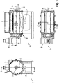
- Fig. 1 shows three different views of the press screw separator 1.
- the Fig. 2 to 3 show the in Fig. 1 marked sections.
- Fig. 5 shows that in Fig. 4 marked detail V.
- the press screw separator 1 comprises a housing 2.
- a cylindrical sieve 3 is arranged.
- a worm 4 is rotatably mounted in the housing 2.
- the worm 4 extends through the cylindrical sieve 3.
- a drive 5 designed as an electric motor or hydraulic motor, is provided.
- an inlet 6 is formed in the housing.
- the pulp to be squeezed out is directed into the interior of the sieve 3.
- a solids outlet 8 is provided at the left end of the screen 3.
- a drain 7 is provided at the bottom of the housing 2, for the liquid components of the slurry. Another sequence 7 is possible at a front end of the hollow screw 4.
- the supplied via the inlet 6 pulp is squeezed by the rotation of the screw 4 from right to left. This forms a solid plug in the left area.
- the solid leaves the press screw separator 1 via the solids outlet 8.
- the separated liquid constituents flow out through the sieve 3 and leave the press screw separator 1 via the outlet 7.
- Fig. 2 shows a conical ring 9 at the solids outlet 8.
- the position of the cone ring 9, the amount of the discharged solid is regulated.
- the screw 4 comprises a screw core 10 and at least one arranged on the screw core 10 screw flight 11.
- the screw core 10 is conical and tapers in the direction of the inlet. 6
- Fig. 2-4 show a longitudinal direction 13.
- this longitudinal direction 13 extend the sieve 3 and the screw 4.
- the screw 4 is rotated about the longitudinal direction 13.
- Perpendicular to the longitudinal direction 13 is a radial direction 14.
- the circumferential direction 15 is defined around the longitudinal direction 13.
- a plurality of washing nozzles 12 are arranged along the longitudinal direction 13.
- a liquid in particular water, can be injected from the outside onto the sieve 3.
- Fig. 3 shows two retaining elements 17, designed as retaining rails.
- the holding elements 17 each extend in the longitudinal direction 13.
- the holding elements 17 are connected via an actuator 16 and guide elements 18 fixed to the housing 2.
- the actuator 16 By means of the actuator 16, the holding elements 13 can be moved inwards, in the direction of the wire 3, and outwardly, away from the wire 3.
- Fig. 3 shows further that 3 stops 19 are formed on the screen.
- the exact design of the holding member 17 and the stopper 19 shows the enlarged view in FIG Fig. 5 ,
- the stop 19 shown is firmly connected to the wire 3.
- the stop 19 abuts against the retaining element 17.
- the position shown in the figures is referred to as the "locking position".
- the actuator 16 By means of the actuator 16, the holding member 17 can be moved to the outside. As a result, the stop 19 is no longer on the holding element 17, whereby a rotation of the wire 3 is possible.
- the guide elements 18 have a housing-fixed cylinder 23. In this cylinder 23, a piston 24 is guided linearly movable. The piston 24 is connected to the holding element 17.
- Fig. 2 shows a Siebrati 20 of the screen 3.
- Fig. 3 shows a holding element length 21 of the holding member 17.
- the holding element length 21 is formed as large as possible, so that over as large a portion of the Siebin 20, the force between the holding member 17 and the stopper 19 can be transmitted.
- Fig. 4 shows a sensor 22. By means of the sensor 22, the rotational movement of the screen 3 is detected.
Landscapes
- Engineering & Computer Science (AREA)
- Mechanical Engineering (AREA)
- Filtration Of Liquid (AREA)
- Treatment Of Sludge (AREA)
Description
- Vorliegende Erfindung betrifft einen Pressschneckenseparator zur Abscheidung fester Bestandteile aus einer feste und flüssige Bestandteile enthaltenden Trübe gemäß Anspruch 1, sowie ein Verfahren zum Betrieb des Pressschneckenseparators gemäß Anspruch 11. Pressschneckenseparatoren weisen ein zylindrisches Sieb auf, wie beispielsweise aus der
US 2011/0186499 A1 bekannt ist. In dem Sieb ist eine rotierende Schnecke angeordnet. Durch die Schnecke wird die Trübe innerhalb des Siebes ausgepresst, so dass die flüssigen Bestandteile durch die Mantelfläche des Siebes hindurchtreten. Am stirnseitigen Ende des Siebes bildet sich ein Feststoffpfropfen. Als Trüben können Abwässer aus kommunalen, industriellen oder landwirtschaftlichen Betrieben (z.B. Gülle oder mit Flockungsmitteln behandelte kommunale Klärschlämme) verwendet werden. Während des Betriebes bedarf es in regelmäßigen Abständen einer Reinigung des Siebes. Ein Pressschneckenseparator gemäß dem Oberbegriff des Anspruchs 1 ist beispielsweise aus derJP 2004-066306 A
Es ist Aufgabe vorliegender Erfindung einen Pressschneckenseparator anzugeben, der bei kostengünstiger Herstellung und Montage wartungsarm betrieben werden kann. Insbesondere soll zu Reinigungszwecken das zylindrische Sieb zusammen mit der Schnecke rotierbar sein. Des Weiteren ist es Aufgabe vorliegender Erfindung ein entsprechendes Verfahren zum Betrieb des Pressschneckenseparators anzugeben.
Die Lösung der Aufgabe erfolgt durch die Merkmale der unabhängigen Ansprüche. Die abhängigen Ansprüche haben vorteilhafte Ausgestaltungen der Erfindung zum Gegenstand.
Somit wird die Aufgabe gelöst durch einen Pressschneckenseparator zur Abscheidung fester Bestandteile aus einer feste und flüssige Bestandteile enthaltenden Trübe. Als Trübe kommen Abwässer aus kommunalen, industriellen oder landwirtschaftlichen Betrieben zum Einsatz, die gegebenenfalls mit Flockungsmitteln stabilisiert werden. Der Pressschneckenseparator umfasst ein Gehäuse und ein im Gehäuse angeordnetes zylindrisches Sieb. Des Weiteren ist in dem Gehäuse eine Schnecke drehbar gelagert. Die Schnecke erstreckt sich zumindest teilweise in das zylindrische Sieb. Entsprechend der zylindrischen Form des Siebes sind eine Längsrichtung und eine Umfangsrichtung definiert. Die Schnecke ist drehbeweglich um die Längsachse gelagert. Zur Reinigung des Siebes ist vorgesehen, dass das Sieb um die Längsrichtung drehbar angeordnet ist. Das Sieb bedarf keines eigenen Antriebes, da bei einem ausreichenden Feststoffgehalt zwischen der Schnecke und dem Sieb ein Drehmoment von der Schnecke auf das Sieb übertragen wird. Erfindungsgemäß ist in dem Gehäuse, insbesondere zwischen einer Gehäusewandung und der Mantelfläche des Siebes, zumindest ein Halteelement angeordnet. Des Weiteren ist ein Aktuator vorgesehen. Mittels des Aktuators kann das Halteelement in eine Verriegelungsposition und in eine Freilaufposition bewegt werden. Ein Ende des Aktuators ist insbesondere fest mit dem Gehäuse verbunden. Das andere Ende des Aktuators ist mit dem Halteelement verbunden. An dem Sieb, insbesondere an der Mantelfläche des Siebes, ist zumindest ein fester Anschlag vorgesehen. Wenn das Halteelement in der Verriegelungsposition steht, liegt der Anschlag am Halteelement an, so dass das Sieb in zumindest einer Richtung drehfest ist. Diese "Verriegelungsposition" wird auch als "Arbeitsposition" bezeichnet. Während der Verriegelungs- oder Arbeitsposition ist das Sieb drehfest und die Trübe kann durch eine Rotation der Schnecke ausgepresst werden. Zum Reinigen des Siebes wird das zumindest eine Halteelement mittels des Aktuators in die Freilaufposition gefahren. Das Halteelement entfernt sich dabei vom Anschlag. In der Freilaufposition rotiert das Sieb mit der Schnecke. Dadurch ist es möglich, das Sieb von allen Seiten zu reinigen. Erfindungsgemäß wird also das Halteelement aktiv, mit dem Aktuator, in die Verriegelungsposition und Freilaufposition bewegt. Das Halteelement und der dazu korrespondierende Anschlag am Sieb können über die gesamte Länge des Siebes wirken, so dass die Kraft zwischen dem Halteelement und dem Anschlag über eine möglichst große Fläche übertragen wird. Des Weiteren ist es erfindungsgemäß möglich, dass die Schnecke sowohl beim Auspressen der Trübe als auch beim Reinigen des Siebes in der gleichen Richtung dreht. - Außerdem ist vorgesehen, dass das Halteelement als eine sich in Längsrichtung erstreckende Halteschiene ausgebildet ist. Die Halteschiene erstreckt sich in Längsrichtung über eine Halteelementlänge. Das Sieb erstreckt sich in Längsrichtung über eine Sieblänge. Bevorzugt ist vorgesehen, dass die Halteelementlänge zumindest 50%, vorzugsweise zumindest 75%, besonders vorzugsweise 100%, der Sieblänge beträgt. Des Weiteren ist bevorzugt vorgesehen, dass sich der Anschlag oder die mehreren Anschläge über zumindest 50%, vorzugsweise über zumindest 75%, besonders vorzugsweise über zumindest 95%, der Halteelementlänge erstrecken.
- Durch die Verwendung einer Halteschiene als Halteelement wird die Kraft zwischen Anschlag und Halteelement über einen möglichst großen Bereich übertragen. Dadurch, dass das Sieb nicht nur an seinen stirnseitigen Enden, sondern entlang seiner gesamten Länge drehfest an der Halteschiene abgestützt ist, muss das Sieb nicht sehr steif ausgebildet sein. Dies hat entscheidende Vorteile während dem Auspressen der Trübe. Beim Auspressen der Trübe verformt sich nämlich das Sieb je nach Position der meist doppelläufigen Schnecke und/oder der Menge des Feststoffes elliptisch. Durch die erfindungsgemäße Ausbildung des Pressschneckenseparators kann das Sieb relativ labil ausgebildet sein, so dass diese Verformung während dem Auspressen der Trübe möglich ist. Des Weiteren kann dadurch der Spalt zwischen den Schneckenflügeln und dem Innendurchmesser des Siebes möglichst gering gehalten werden, da ein Kontakt zwischen den Schneckenflügeln und dem Sieb effektiv vermieden wird.
- Die Halteschiene ist bevorzugt parallel zur Längsrichtung angeordnet. Bei einem Bewegen der Halteschiene in die Freilaufposition wird die Halteschiene von der Mantelfläche des Siebes nach außen wegbewegt. Insbesondere erfolgt diese Bewegung in einer zur Längsrichtung senkrechten Radialrichtung.
- Die Halteschiene ist sowohl in der Verriegelungsposition als auch in der Freilaufposition parallel zur Längsrichtung angeordnet. Hierzu ist die Halteschiene vorzugsweise über zumindest ein Führungselement im Gehäuse gelagert. Dieses Führungselement weist bevorzugt einen gehäusefesten Zylinder auf, in dem ein Kolben geführt ist. Der Kolben ist mit der Halteschiene verbunden.
- In dem Gehäuse sind bevorzugt mehrere, entlang der Längsrichtung verteilte Waschdüsen angeordnet. Mittels dieser Waschdüsen kann Wasser von außen auf das Sieb gespritzt werden, um so das Sieb zu reinigen. Da während dem Reinigen das Sieb rotiert, ist es ausreichend, nur eine Reihe an Waschdüsen anzuordnen.
- Des Weiteren ist bevorzugt ein Sensor zum Erfassen eines Drehwinkels und/oder einer Drehgeschwindigkeit des Siebes vorgesehen. Das Bewegen des zumindest einen Halteelements von der Freilaufposition in die Verriegelungsposition erfolgt bevorzugt in Abhängigkeit der vom Sensor erfassten Daten. Dadurch wird gewährleistet, dass das Halteelement zum richtigen Zeitpunkt in Verriegelungsposition fährt, so dass der Anschlag an dem Halteelement anliegt.
- Des Weiteren ist bevorzugt vorgesehen, dass entlang der Umfangsrichtung des Siebes mehrere Halteelemente vorgesehen sind. Für jedes Halteelement ist zumindest ein Aktuator und jeweils zumindest ein fest mit dem Sieb verbundener Anschlag vorgesehen.
- Der Aktuator ist vorzugsweise hydraulisch, pneumatisch oder elektrisch betrieben.
- Die Schnecke umfasst vorzugsweise eine konische Schneckenseele und zumindest eine auf der Schneckenseele angeordnete Schneckenwendel. Des Weiteren ist am Pressschneckenseparator an einer Stirnseite des zylindrischen Siebes ein Zulauf für die Trübe angeordnet. An der anderen Stirnseite des Siebes ist ein Feststoffauslass ausgebildet. Die konische Schneckenseele verjüngt sich vorzugsweise zum Zulauf hin. Am Feststoffauslass ist vorzugsweise ein Konusring angeordnet, der die Auslassmenge des Feststoffes regelt.
- Die Erfindung umfasst des Weiteren ein Verfahren zum Betrieb des vorgestellten Pressschneckenseparators. Dabei sind folgende Schritte vorgesehen: (i) Auspressen der Trübe, wobei die Schnecke rotiert und das Halteelement in der Verriegelungsposition ist, (ii) Bewegen des Halteelements in die Freilaufposition, (iii) Rotieren der Schnecke, während das Halteelement in der Freilaufposition ist, so dass das Sieb mit der Schnecke rotiert, und (iv) Reinigen des Siebes, währen das Sieb mit der Schnecke rotiert.
- Bevor das Halteelement in die Freilaufposition bewegt wird, erfolgt vorzugsweise ein kurzzeitiges Ausschalten des Antriebs der Schnecke. Sobald das Halteelement in der Freilaufposition ist, wird die Schnecke wieder in Rotation versetzt. Insbesondere rotiert die Schnecke zum Auspressen der Trübe als auch während dem Reinigen des Siebes in der gleichen Richtung. Zum Reinigen des Siebes werden insbesondere die erwähnten Waschdüsen eingeschaltet. Die Rotation des Siebes wird mit dem Sensor überwacht. Der Sensor gibt einen bestimmten Drehweg des Siebes an den Aktuator weiter. Dementsprechend fährt der Aktuator das Halteelement wieder in die Verriegelungsposition. Das Sieb wird dabei von den Halteelementen eingefangen und am Weiterdrehen gehindert. Daraufhin kann wieder das Auspressen der Trübe erfolgen.
- Die Halteelemente können auch zu Wartungsarbeiten verstellt werden, um beispielsweise ein Herabfallen des Siebes beim Demontieren der Schnecke zu verhindern.
- Die Unteransprüche des erfindungsgemäßen Pressschneckenseparators sowie die vorgestellten Ausbildungen des Pressschneckenseparators finden entsprechend vorteilhafte Anwendung auf das erfindungsgemäße Verfahren.
- Im Folgenden wird ein Ausführungsbeispiel der Erfindung unter Bezugnahme auf die begleitende Zeichnung im Detail erläutert. Dabei zeigen:
- Fig. 1
- drei Ansichten eines erfindungsgemäßen Pressschneckenseparators gemäß einem Ausführungsbeispiel,
- Fig. 2
- den in
Fig. 1 gekennzeichneten Schnitt B-B, - Fig. 3
- den in
Fig. 1 gekennzeichneten Schnitt A-A, - Fig. 4
- den in
Fig. 1 gekennzeichneten Schnitt C-C, und - Fig. 5
- das in
Fig. 4 gekennzeichnete Detail V. - Im Folgenden wird anhand der
Fig. 1 bis 5 ein Ausführungsbeispiel eines Pressschneckenseparators 1 gezeigt.Fig. 1 zeigt drei verschiedene Ansichten des Pressschneckenseparators 1. DieFig. 2 bis 3 zeigen die inFig. 1 gekennzeichneten Schnitte.Fig. 5 zeigt das inFig. 4 gekennzeichnete Detail V. - Der Pressschneckenseparator 1 umfasst ein Gehäuse 2. In dem Gehäuse 2 ist ein zylindrisches Sieb 3 angeordnet. Des Weiteren ist in dem Gehäuse 2 eine Schnecke 4 drehbar gelagert. Die Schnecke 4 erstreckt sich durch das zylindrische Sieb 3.
- Zum Rotieren der Schnecke 4 ist ein Antrieb 5, ausgebildet als Elektromotor oder Hydraulikmotor, vorgesehen.
- An der rechten Stirnseite des Siebes 3 ist ein Zulauf 6 im Gehäuse ausgebildet. Mittels des Zulaufs 6 wird die auszupressende Trübe in den Innenraum des Siebes 3 geleitet. An der linken Stirnseite des Siebes 3 ist ein Feststoffauslass 8 vorgesehen. An der Unterseite des Gehäuses 2 ist ein Ablauf 7 für die flüssigen Bestandteile der Trübe vorgesehen. Ein weiterer Ablauf 7 ist an einem stirnseitigen Ende der hohlen Schnecke 4 möglich.
- Die über den Zulauf 6 zugeführte Trübe wird durch die Rotation der Schnecke 4 von rechts nach links ausgepresst. Dadurch bildet sich im linken Bereich ein Feststoffpfropfen. Der Feststoff verlässt den Pressschneckenseparator 1 über den Feststoffauslass 8. Die abgetrennten flüssigen Bestandteile fließen durch das Sieb 3 nach außen und verlassen den Pressschneckenseparator 1 über den Ablauf 7.
-
Fig. 2 zeigt einen Konusring 9 am Feststoffauslass 8. Durch die Position des Konusrings 9 wird die Menge des abgegebenen Feststoffes reguliert. - Des Weiteren zeigt
Fig. 2 die genaue Ausbildung der Schnecke 4. Die Schnecke 4 umfasst eine Schneckenseele 10 und zumindest eine auf der Schneckenseele 10 angeordnete Schneckenwendel 11. Die Schneckenseele 10 ist konisch ausgebildet und verjüngt sich in Richtung des Zulaufes 6. -
Fig. 2 - 4 zeigen eine Längsrichtung 13. In dieser Längsrichtung 13 erstrecken sich das Sieb 3 und die Schnecke 4. Mittels des Antriebs 5 wird die Schnecke 4 um die Längsrichtung 13 gedreht. Senkrecht zur Längsrichtung 13 steht eine Radialrichtung 14. Um die Längsrichtung 13 ist die Umfangsrichtung 15 definiert. - In dem Gehäuse 2 sind entlang der Längsrichtung 13 mehrere Waschdüsen 12 angeordnet. Mittels der Waschdüsen 12 kann eine Flüssigkeit, insbesondere Wasser, von außen auf das Sieb 3 gespritzt werden.
-
Fig. 3 zeigt zwei Halteelemente 17, ausgebildet als Halteschienen. Die Halteelemente 17 erstrecken sich jeweils in Längsrichtung 13. Die Halteelemente 17 sind über einen Aktuator 16 und über Führungselemente 18 fest mit dem Gehäuse 2 verbunden. Mittels des Aktuators 16 können die Halteelemente 13 nach innen, in Richtung des Siebes 3, und nach außen, von dem Sieb 3 weg, bewegt werden. -
Fig. 3 zeigt des Weiteren, dass an dem Sieb 3 Anschläge 19 ausgebildet sind. Die genaue Ausbildung des Halteelements 17 und des Anschlags 19 zeigt die vergrößerte Darstellung inFig. 5 . Der gezeigte Anschlag 19 ist fest mit dem Sieb 3 verbunden. Der Anschlag 19 liegt an dem Halteelement 17 an. Dadurch ist das Sieb drehfest aufgenommen. Die in den Figuren gezeigte Stellung wird als "Verriegelungsposition" bezeichnet. Mittels des Aktuators 16 kann das Halteelement 17 nach außen bewegt werden. Dadurch liegt der Anschlag 19 nicht mehr am Halteelement 17 an, wodurch ein Rotieren des Siebes 3 möglich ist. - Die Führungselemente 18 weisen einen gehäusefesten Zylinder 23 auf. In diesem Zylinder 23 ist ein Kolben 24 linear beweglich geführt. Der Kolben 24 ist mit dem Halteelement 17 verbunden.
-
Fig. 2 zeigt eine Sieblänge 20 des Siebes 3.Fig. 3 zeigt eine Halteelementlänge 21 des Halteelements 17. Die Halteelementlänge 21 ist möglichst groß ausgebildet, so dass über einen möglichst großen Anteil der Sieblänge 20 die Kraft zwischen dem Halteelement 17 und dem Anschlag 19 übertragen werden kann. -
Fig. 4 zeigt einen Sensor 22. Mittels des Sensors 22 wird die Drehbewegung des Siebes 3 erfasst. - Beim Auspressen der Trübe bildet sich ein Feststoffpfropfen in dem Ringspalt zwischen der Schneckenseele 10 und dem Sieb 3. Dieser Feststoffpfropfen überträgt ein Drehmoment von der Schnecke 4 auf das Sieb 3. Wenn sich die Halteelemente 17 in der Verriegelungsposition befinden, ist das Sieb 3 drehfest und es kann ein Auspressen der Trübe erfolgen. Zum Reinigen des Siebes 3 werden die Halteelemente 17 nach außen bewegt, so dass das Sieb 3 zusammen mit der Schnecke 4 rotiert. Durch Aktivieren der Waschdüsen 12 kann somit der gesamte Umfang des Siebes 3 gereinigt werden. Der Sensor 23 erfasst die Drehbewegung des Siebes 3 und kann zum richtigen Zeitpunkt die Aktuatoren 16 ansteuern, so dass die Halteelemente 17 wieder in die Verriegelungsposition bewegt werden.
-
- 1
- Pressschneckenseparator
- 2
- Gehäuse
- 3
- Sieb
- 4
- Schnecke
- 5
- Antrieb
- 6
- Zulauf
- 7
- Ablauf
- 8
- Feststoffauslass
- 9
- Konusring
- 10
- Schneckenseele
- 11
- Schneckenwendel
- 12
- Waschdüsen
- 13
- Längsrichtung
- 14
- Radialrichtung
- 15
- Umfangsrichtung
- 16
- Aktuator
- 17
- Halteelement
- 18
- Führungselement
- 19
- Anschlag
- 20
- Sieblänge
- 21
- Halteelementlänge
- 22
- Sensor
- 23
- Zylinder
- 24
- Kolben
Claims (11)
- Pressschneckenseparator (1) zur Abscheidung fester Bestandteile aus einer feste und flüssige Bestandteile enthaltenden Trübe umfassend- ein Gehäuse (2),- ein im Gehäuse (2) angeordnetes zylindrisches Sieb (3), an dem eine Längsrichtung (13) und eine Umfangsrichtung (15) definiert sind, wobei das Sieb (3) drehbeweglich um die Längsrichtung (13) ist,- eine innerhalb des Siebes (3) angeordnete Schnecke (4) zum Auspressen der Trübe, wobei die Schnecke (4) drehbeweglich um die Längsrichtung (13) ist,- zumindest ein im Gehäuse (2) angeordnetes Haltelement (17),- zumindest einen Aktuator (16) zum Bewegen des zumindest einen Halteelements (17) zwischen einer Verriegelungsposition und einer Freilaufposition,- zumindest einen fest mit dem Sieb (3) verbundenen Anschlag (19), der zum Anliegen am Haltelement (17) in der Verriegelungsposition ausgebildet ist, sodass in der Verriegelungsposition das Sieb (3) in zumindest einer Umfangsrichtung (15) drehfest ist und in der Freilaufposition das Sieb (3) mit der Schnecke (4) mitdreht,wobei durch die festen Bestandteile der Trübe ein Drehmoment von der Schnecke (4) auf das Sieb (3) übertragbar ist, um das Sieb (3) in der Freilaufposition des Halteelements (17) anzutreiben, dadurch gekennzeichnet, dass das Haltelement (17) als eine sich in Längsrichtung (13) erstreckende Halteschiene ausgebildet ist.
- Pressschneckenseparator nach Anspruch 1, dadurch gekennzeichnet, dass sich die Halteschiene in Längsrichtung (13) über eine Haltelementlänge (21) und das Sieb (3) in Längsrichtung (13) über eine Sieblänge (20) erstrecken, wobei die Haltelementlänge (21) zumindest 50%, vorzugsweise zumindest 75%, der Sieblänge (20) beträgt.
- Pressschneckenseparator nach Anspruch 1 oder 2, dadurch gekennzeichnet, dass sich der Anschlag (19) oder die mehreren Anschläge über zumindest 50%, vorzugsweise über zumindest 75%, der Haltelementlänge (21) erstrecken.
- Pressschneckenseparator nach einem der vorhergehenden Ansprüche, dadurch gekennzeichnet, dass die Halteschiene in der Verriegelungsposition und in der Freilaufposition parallel zu Längsrichtung (13) angeordnet ist.
- Pressschneckenseparator nach einem der vorhergehenden Ansprüche, dadurch gekennzeichnet, dass im Gehäuse (2) mehrere, entlang der Längsrichtung (13) verteilte Waschdüsen (12) angeordnet sind.
- Pressschneckenseparator nach einem der vorhergehenden Ansprüche, gekennzeichnet durch einen Sensor (22) zum Erfassen eines Drehwinkels und/oder einer Drehgeschwindigkeit des Siebes (3).
- Pressschneckenseparator nach einem der vorhergehenden Ansprüche, gekennzeichnet durch mehrere, entlang der Umfangsrichtung (15) des Siebes (3) verteilte Halteelemente (17) mit jeweils zumindest einem Aktuator (16) und jeweils zumindest einem fest mit dem Sieb (3) verbundenen Anschlag (19).
- Pressschneckenseparator nach einem der vorhergehenden Ansprüche, dadurch gekennzeichnet, dass der Aktuator (16) hydraulisch oder pneumatisch oder elektrisch betrieben ist.
- Pressschneckenseparator nach einem der vorhergehenden Ansprüche, dadurch gekennzeichnet, dass die Schnecke (4) eine konische Schneckenseele (10) und zumindest eine auf der Schneckenseele (10) angeordnete Schneckenwendel (11) umfasst.
- Pressschneckenseparator nach einem der vorhergehenden Ansprüche, dadurch gekennzeichnet, dass an einer Stirnseite des zylindrischen Siebes (3) ein Zulauf (6) für die Trübe ausgebildet ist, und an der anderen Stirnseite ein Feststoffauslass (8) ausgebildet ist.
- Verfahren zum Betrieb eines Pressschneckenseparators (1) nach einem der vorhergehenden Ansprüche, umfassend die folgenden Schritte:- Auspressen einer Trübe, wobei die Schnecke (4) rotiert und das Haltelement (17) in der Verriegelungsposition ist,- Bewegen des Halteelementes (17) in die Freilaufposition,- Rotieren der Schnecke (4), während das Haltelement (17) in der Freilaufposition ist, sodass das Sieb (3) mit der Schnecke (4) rotiert, und- Reinigen des Siebes (3), während das Sieb (3) mit der Schnecke (4) rotiert.
Priority Applications (6)
| Application Number | Priority Date | Filing Date | Title |
|---|---|---|---|
| EP13000088.8A EP2754552B1 (de) | 2013-01-09 | 2013-01-09 | Pressschneckenseparator und Verfahren zum Betrieb des Pressschneckenseparators |
| PL13000088T PL2754552T3 (pl) | 2013-01-09 | 2013-01-09 | Separator ślimakowy oraz sposób działania separatora ślimakowego |
| ES13000088.8T ES2681047T3 (es) | 2013-01-09 | 2013-01-09 | Separador por presión helicoidal y procedimiento para la operación del separador por presión helicoidal |
| HUE13000088A HUE038801T2 (hu) | 2013-01-09 | 2013-01-09 | Préscsigás szeparátor és eljárás préscsigás szeparátor üzemeltetésére |
| PCT/EP2014/050018 WO2014108349A1 (de) | 2013-01-09 | 2014-01-02 | Pressschneckenseparator und verfahren zum betrieb des pressschneckenseparators |
| US14/760,088 US10195806B2 (en) | 2013-01-09 | 2014-01-02 | Screw press separator and method for operating the screw press separator |
Applications Claiming Priority (1)
| Application Number | Priority Date | Filing Date | Title |
|---|---|---|---|
| EP13000088.8A EP2754552B1 (de) | 2013-01-09 | 2013-01-09 | Pressschneckenseparator und Verfahren zum Betrieb des Pressschneckenseparators |
Publications (2)
| Publication Number | Publication Date |
|---|---|
| EP2754552A1 EP2754552A1 (de) | 2014-07-16 |
| EP2754552B1 true EP2754552B1 (de) | 2018-05-02 |
Family
ID=47522375
Family Applications (1)
| Application Number | Title | Priority Date | Filing Date |
|---|---|---|---|
| EP13000088.8A Active EP2754552B1 (de) | 2013-01-09 | 2013-01-09 | Pressschneckenseparator und Verfahren zum Betrieb des Pressschneckenseparators |
Country Status (6)
| Country | Link |
|---|---|
| US (1) | US10195806B2 (de) |
| EP (1) | EP2754552B1 (de) |
| ES (1) | ES2681047T3 (de) |
| HU (1) | HUE038801T2 (de) |
| PL (1) | PL2754552T3 (de) |
| WO (1) | WO2014108349A1 (de) |
Families Citing this family (6)
| Publication number | Priority date | Publication date | Assignee | Title |
|---|---|---|---|---|
| CA2970289C (en) * | 2013-07-26 | 2020-07-07 | Ishigaki Company Limited | Recovery device and recovery method for recovering specific material from sludge |
| US10486383B1 (en) * | 2018-12-18 | 2019-11-26 | V.Y.F. Express Inc. | Screw press having screen vibration |
| US12257588B2 (en) | 2019-01-09 | 2025-03-25 | Jeremy Leonard | Centrifugal separator |
| US11162218B1 (en) | 2020-09-30 | 2021-11-02 | Robert Clayton | Biomass pulp digester |
| CN216155724U (zh) * | 2021-09-02 | 2022-04-01 | 吴云萍 | 一种具有可拆卸式驱动装置的无磨损叠片螺旋脱水设备 |
| DE102022120864A1 (de) * | 2022-08-18 | 2024-02-29 | Huber Se | Vorrichtung zum Entwässern und Verdichten von Pressgut sowie Verfahren zum Betreiben einer solchen Vorrichtung |
Family Cites Families (11)
| Publication number | Priority date | Publication date | Assignee | Title |
|---|---|---|---|---|
| US4844799A (en) * | 1986-07-17 | 1989-07-04 | Lee Chung Y | Filtration apparatus having spaced-apart driving members for changing a size of a treatment zone |
| US5357855A (en) * | 1991-09-24 | 1994-10-25 | Ishigaki Mechanical Industry Co., Ltd. | Screw press for dewatering a slurry |
| JP2868146B2 (ja) * | 1994-06-09 | 1999-03-10 | 株式会社石垣 | スクリュープレスの外筒スクリーンの洗浄装置 |
| DE69938792D1 (de) * | 1999-11-30 | 2008-07-03 | Ishigaki Co Ltd | Schraubenpresse |
| JP2003033896A (ja) * | 2001-07-17 | 2003-02-04 | Kubota Corp | スクリュープレスの外胴構造 |
| JP3944723B2 (ja) * | 2002-08-07 | 2007-07-18 | 株式会社石垣 | 濃縮機能を有するスクリュープレス |
| JP4472459B2 (ja) * | 2004-08-11 | 2010-06-02 | 前澤工業株式会社 | スクリュープレスのスクリーン洗浄装置 |
| JP4427798B2 (ja) * | 2005-04-14 | 2010-03-10 | 株式会社石垣 | 差速回転濃縮機における運転制御方法並びに運転制御装置 |
| DE202010001758U1 (de) * | 2010-02-02 | 2011-06-09 | UTS Biogastechnik GmbH, 85399 | Schneckenseparator |
| KR101106168B1 (ko) * | 2011-09-30 | 2012-01-18 | 주식회사 이앤에프 | 스크류탈수기 |
| US9561978B2 (en) * | 2012-04-20 | 2017-02-07 | Anaergia Inc. | Sludge screw thickener with screen rotation during cleaning |
-
2013
- 2013-01-09 ES ES13000088.8T patent/ES2681047T3/es active Active
- 2013-01-09 HU HUE13000088A patent/HUE038801T2/hu unknown
- 2013-01-09 EP EP13000088.8A patent/EP2754552B1/de active Active
- 2013-01-09 PL PL13000088T patent/PL2754552T3/pl unknown
-
2014
- 2014-01-02 WO PCT/EP2014/050018 patent/WO2014108349A1/de not_active Ceased
- 2014-01-02 US US14/760,088 patent/US10195806B2/en active Active
Non-Patent Citations (1)
| Title |
|---|
| None * |
Also Published As
| Publication number | Publication date |
|---|---|
| HUE038801T2 (hu) | 2018-11-28 |
| PL2754552T3 (pl) | 2018-12-31 |
| EP2754552A1 (de) | 2014-07-16 |
| US10195806B2 (en) | 2019-02-05 |
| US20160001516A1 (en) | 2016-01-07 |
| WO2014108349A1 (de) | 2014-07-17 |
| ES2681047T3 (es) | 2018-09-11 |
Similar Documents
| Publication | Publication Date | Title |
|---|---|---|
| EP2754552B1 (de) | Pressschneckenseparator und Verfahren zum Betrieb des Pressschneckenseparators | |
| EP2411152B1 (de) | Schneidvorrichtung | |
| DE69304281T2 (de) | Gerät zum trennen von feststoffen und flüssigkeiten | |
| EP2201993A1 (de) | Fluidfilter | |
| EP2938418A1 (de) | Pressschneckenseparator | |
| DE202016103608U1 (de) | Filtervorrichtung und Reinigungseinrichtung zum Entfernen von Schmutzpartikeln von einem Filterelement einer Filtervorrichtung Filtervorrichtung und Reinigungseinrichtung zum Entfernen von Schmutzpartikeln von einem Filterelement einer Filtervorrichtung | |
| WO2005063357A1 (de) | Vorrichtung zum kontinuierlichen filtern von materialgemischen | |
| EP2022760A2 (de) | Filterkartusche für eine Wasserfiltervorrichtung | |
| EP2112336B1 (de) | Gemeinsame Ölversorgung des VCT und der Nockenwellenlager über eine hohle Nockenwelle | |
| DE102008021935A1 (de) | Schneckenpresse | |
| DE202010001759U1 (de) | Schneckenseparator | |
| DD201854A5 (de) | Filterapparat zur abtrennung von fest- und schwebstoffen aus fluessigkeiten | |
| DE102018105079A1 (de) | Vollmantel-Schneckenzentrifuge | |
| EP3160711B1 (de) | Schmelzefilteranordnung mit rückspül-schneckenfördereinrichtung | |
| DE69806346T2 (de) | Vorrichtung zur abtrennung einer substanz im wesentlichen in eine feste und flüssige phase | |
| EP2907646A1 (de) | Grobpartikelabscheidevorrichtung | |
| EP1305098B1 (de) | Abscheidevorrichtung zum abscheiden von flüssigkeit aus feststoffen sowie deren verwendung | |
| EP2707206B1 (de) | Pressschneckenseparator | |
| EP3535039B1 (de) | Filtereinrichtung | |
| EP1949966B1 (de) | Vollmantel-Schneckenzentrifuge mit einer Stauscheibe | |
| EP3105045B1 (de) | Pressschneckenseparator | |
| DE102014102585A1 (de) | Entwässerungsvorrichtung sowie Verfahren zum Entwässern von Schlamm | |
| DE202012011864U1 (de) | Pressschneckenseparator | |
| EP3094479B1 (de) | Pressschnecke für einen pressschneckenseparator | |
| AT525727B1 (de) | Pressschneckenseparator |
Legal Events
| Date | Code | Title | Description |
|---|---|---|---|
| PUAI | Public reference made under article 153(3) epc to a published international application that has entered the european phase |
Free format text: ORIGINAL CODE: 0009012 |
|
| 17P | Request for examination filed |
Effective date: 20130109 |
|
| AK | Designated contracting states |
Kind code of ref document: A1 Designated state(s): AL AT BE BG CH CY CZ DE DK EE ES FI FR GB GR HR HU IE IS IT LI LT LU LV MC MK MT NL NO PL PT RO RS SE SI SK SM TR |
|
| AX | Request for extension of the european patent |
Extension state: BA ME |
|
| R17P | Request for examination filed (corrected) |
Effective date: 20140822 |
|
| RBV | Designated contracting states (corrected) |
Designated state(s): AL AT BE BG CH CY CZ DE DK EE ES FI FR GB GR HR HU IE IS IT LI LT LU LV MC MK MT NL NO PL PT RO RS SE SI SK SM TR |
|
| STAA | Information on the status of an ep patent application or granted ep patent |
Free format text: STATUS: EXAMINATION IS IN PROGRESS |
|
| 17Q | First examination report despatched |
Effective date: 20170621 |
|
| GRAP | Despatch of communication of intention to grant a patent |
Free format text: ORIGINAL CODE: EPIDOSNIGR1 |
|
| STAA | Information on the status of an ep patent application or granted ep patent |
Free format text: STATUS: GRANT OF PATENT IS INTENDED |
|
| INTG | Intention to grant announced |
Effective date: 20171117 |
|
| GRAS | Grant fee paid |
Free format text: ORIGINAL CODE: EPIDOSNIGR3 |
|
| GRAA | (expected) grant |
Free format text: ORIGINAL CODE: 0009210 |
|
| STAA | Information on the status of an ep patent application or granted ep patent |
Free format text: STATUS: THE PATENT HAS BEEN GRANTED |
|
| AK | Designated contracting states |
Kind code of ref document: B1 Designated state(s): AL AT BE BG CH CY CZ DE DK EE ES FI FR GB GR HR HU IE IS IT LI LT LU LV MC MK MT NL NO PL PT RO RS SE SI SK SM TR |
|
| REG | Reference to a national code |
Ref country code: GB Ref legal event code: FG4D Free format text: NOT ENGLISH |
|
| REG | Reference to a national code |
Ref country code: CH Ref legal event code: EP Ref country code: AT Ref legal event code: REF Ref document number: 994745 Country of ref document: AT Kind code of ref document: T Effective date: 20180515 |
|
| REG | Reference to a national code |
Ref country code: DE Ref legal event code: R096 Ref document number: 502013010032 Country of ref document: DE Ref country code: IE Ref legal event code: FG4D Free format text: LANGUAGE OF EP DOCUMENT: GERMAN |
|
| REG | Reference to a national code |
Ref country code: NL Ref legal event code: FP |
|
| REG | Reference to a national code |
Ref country code: ES Ref legal event code: FG2A Ref document number: 2681047 Country of ref document: ES Kind code of ref document: T3 Effective date: 20180911 |
|
| REG | Reference to a national code |
Ref country code: LT Ref legal event code: MG4D |
|
| REG | Reference to a national code |
Ref country code: NO Ref legal event code: T2 Effective date: 20180502 |
|
| PG25 | Lapsed in a contracting state [announced via postgrant information from national office to epo] |
Ref country code: FI Free format text: LAPSE BECAUSE OF FAILURE TO SUBMIT A TRANSLATION OF THE DESCRIPTION OR TO PAY THE FEE WITHIN THE PRESCRIBED TIME-LIMIT Effective date: 20180502 Ref country code: BG Free format text: LAPSE BECAUSE OF FAILURE TO SUBMIT A TRANSLATION OF THE DESCRIPTION OR TO PAY THE FEE WITHIN THE PRESCRIBED TIME-LIMIT Effective date: 20180802 Ref country code: SE Free format text: LAPSE BECAUSE OF FAILURE TO SUBMIT A TRANSLATION OF THE DESCRIPTION OR TO PAY THE FEE WITHIN THE PRESCRIBED TIME-LIMIT Effective date: 20180502 Ref country code: LT Free format text: LAPSE BECAUSE OF FAILURE TO SUBMIT A TRANSLATION OF THE DESCRIPTION OR TO PAY THE FEE WITHIN THE PRESCRIBED TIME-LIMIT Effective date: 20180502 |
|
| REG | Reference to a national code |
Ref country code: HU Ref legal event code: AG4A Ref document number: E038801 Country of ref document: HU |
|
| PG25 | Lapsed in a contracting state [announced via postgrant information from national office to epo] |
Ref country code: LV Free format text: LAPSE BECAUSE OF FAILURE TO SUBMIT A TRANSLATION OF THE DESCRIPTION OR TO PAY THE FEE WITHIN THE PRESCRIBED TIME-LIMIT Effective date: 20180502 Ref country code: HR Free format text: LAPSE BECAUSE OF FAILURE TO SUBMIT A TRANSLATION OF THE DESCRIPTION OR TO PAY THE FEE WITHIN THE PRESCRIBED TIME-LIMIT Effective date: 20180502 Ref country code: GR Free format text: LAPSE BECAUSE OF FAILURE TO SUBMIT A TRANSLATION OF THE DESCRIPTION OR TO PAY THE FEE WITHIN THE PRESCRIBED TIME-LIMIT Effective date: 20180803 Ref country code: RS Free format text: LAPSE BECAUSE OF FAILURE TO SUBMIT A TRANSLATION OF THE DESCRIPTION OR TO PAY THE FEE WITHIN THE PRESCRIBED TIME-LIMIT Effective date: 20180502 |
|
| PG25 | Lapsed in a contracting state [announced via postgrant information from national office to epo] |
Ref country code: EE Free format text: LAPSE BECAUSE OF FAILURE TO SUBMIT A TRANSLATION OF THE DESCRIPTION OR TO PAY THE FEE WITHIN THE PRESCRIBED TIME-LIMIT Effective date: 20180502 Ref country code: DK Free format text: LAPSE BECAUSE OF FAILURE TO SUBMIT A TRANSLATION OF THE DESCRIPTION OR TO PAY THE FEE WITHIN THE PRESCRIBED TIME-LIMIT Effective date: 20180502 Ref country code: RO Free format text: LAPSE BECAUSE OF FAILURE TO SUBMIT A TRANSLATION OF THE DESCRIPTION OR TO PAY THE FEE WITHIN THE PRESCRIBED TIME-LIMIT Effective date: 20180502 Ref country code: CZ Free format text: LAPSE BECAUSE OF FAILURE TO SUBMIT A TRANSLATION OF THE DESCRIPTION OR TO PAY THE FEE WITHIN THE PRESCRIBED TIME-LIMIT Effective date: 20180502 Ref country code: SK Free format text: LAPSE BECAUSE OF FAILURE TO SUBMIT A TRANSLATION OF THE DESCRIPTION OR TO PAY THE FEE WITHIN THE PRESCRIBED TIME-LIMIT Effective date: 20180502 |
|
| REG | Reference to a national code |
Ref country code: DE Ref legal event code: R097 Ref document number: 502013010032 Country of ref document: DE |
|
| PG25 | Lapsed in a contracting state [announced via postgrant information from national office to epo] |
Ref country code: SM Free format text: LAPSE BECAUSE OF FAILURE TO SUBMIT A TRANSLATION OF THE DESCRIPTION OR TO PAY THE FEE WITHIN THE PRESCRIBED TIME-LIMIT Effective date: 20180502 |
|
| PLBE | No opposition filed within time limit |
Free format text: ORIGINAL CODE: 0009261 |
|
| STAA | Information on the status of an ep patent application or granted ep patent |
Free format text: STATUS: NO OPPOSITION FILED WITHIN TIME LIMIT |
|
| 26N | No opposition filed |
Effective date: 20190205 |
|
| PG25 | Lapsed in a contracting state [announced via postgrant information from national office to epo] |
Ref country code: SI Free format text: LAPSE BECAUSE OF FAILURE TO SUBMIT A TRANSLATION OF THE DESCRIPTION OR TO PAY THE FEE WITHIN THE PRESCRIBED TIME-LIMIT Effective date: 20180502 |
|
| PG25 | Lapsed in a contracting state [announced via postgrant information from national office to epo] |
Ref country code: MC Free format text: LAPSE BECAUSE OF FAILURE TO SUBMIT A TRANSLATION OF THE DESCRIPTION OR TO PAY THE FEE WITHIN THE PRESCRIBED TIME-LIMIT Effective date: 20180502 |
|
| REG | Reference to a national code |
Ref country code: CH Ref legal event code: PL |
|
| GBPC | Gb: european patent ceased through non-payment of renewal fee |
Effective date: 20190109 |
|
| REG | Reference to a national code |
Ref country code: IE Ref legal event code: MM4A |
|
| PG25 | Lapsed in a contracting state [announced via postgrant information from national office to epo] |
Ref country code: AL Free format text: LAPSE BECAUSE OF FAILURE TO SUBMIT A TRANSLATION OF THE DESCRIPTION OR TO PAY THE FEE WITHIN THE PRESCRIBED TIME-LIMIT Effective date: 20180502 |
|
| PG25 | Lapsed in a contracting state [announced via postgrant information from national office to epo] |
Ref country code: LI Free format text: LAPSE BECAUSE OF NON-PAYMENT OF DUE FEES Effective date: 20190131 Ref country code: CH Free format text: LAPSE BECAUSE OF NON-PAYMENT OF DUE FEES Effective date: 20190131 Ref country code: GB Free format text: LAPSE BECAUSE OF NON-PAYMENT OF DUE FEES Effective date: 20190109 |
|
| PG25 | Lapsed in a contracting state [announced via postgrant information from national office to epo] |
Ref country code: IE Free format text: LAPSE BECAUSE OF NON-PAYMENT OF DUE FEES Effective date: 20190109 |
|
| PG25 | Lapsed in a contracting state [announced via postgrant information from national office to epo] |
Ref country code: TR Free format text: LAPSE BECAUSE OF FAILURE TO SUBMIT A TRANSLATION OF THE DESCRIPTION OR TO PAY THE FEE WITHIN THE PRESCRIBED TIME-LIMIT Effective date: 20180502 |
|
| PG25 | Lapsed in a contracting state [announced via postgrant information from national office to epo] |
Ref country code: PT Free format text: LAPSE BECAUSE OF FAILURE TO SUBMIT A TRANSLATION OF THE DESCRIPTION OR TO PAY THE FEE WITHIN THE PRESCRIBED TIME-LIMIT Effective date: 20180903 Ref country code: MT Free format text: LAPSE BECAUSE OF FAILURE TO SUBMIT A TRANSLATION OF THE DESCRIPTION OR TO PAY THE FEE WITHIN THE PRESCRIBED TIME-LIMIT Effective date: 20180502 |
|
| PG25 | Lapsed in a contracting state [announced via postgrant information from national office to epo] |
Ref country code: CY Free format text: LAPSE BECAUSE OF FAILURE TO SUBMIT A TRANSLATION OF THE DESCRIPTION OR TO PAY THE FEE WITHIN THE PRESCRIBED TIME-LIMIT Effective date: 20180502 |
|
| PG25 | Lapsed in a contracting state [announced via postgrant information from national office to epo] |
Ref country code: IS Free format text: LAPSE BECAUSE OF FAILURE TO SUBMIT A TRANSLATION OF THE DESCRIPTION OR TO PAY THE FEE WITHIN THE PRESCRIBED TIME-LIMIT Effective date: 20180902 |
|
| PG25 | Lapsed in a contracting state [announced via postgrant information from national office to epo] |
Ref country code: MK Free format text: LAPSE BECAUSE OF FAILURE TO SUBMIT A TRANSLATION OF THE DESCRIPTION OR TO PAY THE FEE WITHIN THE PRESCRIBED TIME-LIMIT Effective date: 20180502 |
|
| PGFP | Annual fee paid to national office [announced via postgrant information from national office to epo] |
Ref country code: LU Payment date: 20260121 Year of fee payment: 14 Ref country code: NL Payment date: 20260121 Year of fee payment: 14 |
|
| PGFP | Annual fee paid to national office [announced via postgrant information from national office to epo] |
Ref country code: HU Payment date: 20260113 Year of fee payment: 14 |
|
| PGFP | Annual fee paid to national office [announced via postgrant information from national office to epo] |
Ref country code: ES Payment date: 20260217 Year of fee payment: 14 |
|
| PGFP | Annual fee paid to national office [announced via postgrant information from national office to epo] |
Ref country code: NO Payment date: 20260120 Year of fee payment: 14 Ref country code: DE Payment date: 20260128 Year of fee payment: 14 |
|
| PGFP | Annual fee paid to national office [announced via postgrant information from national office to epo] |
Ref country code: AT Payment date: 20260119 Year of fee payment: 14 |
|
| PGFP | Annual fee paid to national office [announced via postgrant information from national office to epo] |
Ref country code: IT Payment date: 20260130 Year of fee payment: 14 Ref country code: BE Payment date: 20260121 Year of fee payment: 14 |
|
| PGFP | Annual fee paid to national office [announced via postgrant information from national office to epo] |
Ref country code: FR Payment date: 20260121 Year of fee payment: 14 |
|
| PGFP | Annual fee paid to national office [announced via postgrant information from national office to epo] |
Ref country code: PL Payment date: 20260102 Year of fee payment: 14 |