EP2754821B1 - Karusseltür und verfahren zur anordnung einer antriebseinheit in einer karusseltür - Google Patents
Karusseltür und verfahren zur anordnung einer antriebseinheit in einer karusseltür Download PDFInfo
- Publication number
- EP2754821B1 EP2754821B1 EP14000023.3A EP14000023A EP2754821B1 EP 2754821 B1 EP2754821 B1 EP 2754821B1 EP 14000023 A EP14000023 A EP 14000023A EP 2754821 B1 EP2754821 B1 EP 2754821B1
- Authority
- EP
- European Patent Office
- Prior art keywords
- revolving door
- pole motor
- adapter element
- turnstile
- drive unit
- Prior art date
- Legal status (The legal status is an assumption and is not a legal conclusion. Google has not performed a legal analysis and makes no representation as to the accuracy of the status listed.)
- Active
Links
Images

Classifications
-
- E—FIXED CONSTRUCTIONS
- E05—LOCKS; KEYS; WINDOW OR DOOR FITTINGS; SAFES
- E05F—DEVICES FOR MOVING WINGS INTO OPEN OR CLOSED POSITION; CHECKS FOR WINGS; WING FITTINGS NOT OTHERWISE PROVIDED FOR, CONCERNED WITH THE FUNCTIONING OF THE WING
- E05F15/00—Power-operated mechanisms for wings
- E05F15/40—Safety devices, e.g. detection of obstructions or end positions
-
- E—FIXED CONSTRUCTIONS
- E05—LOCKS; KEYS; WINDOW OR DOOR FITTINGS; SAFES
- E05F—DEVICES FOR MOVING WINGS INTO OPEN OR CLOSED POSITION; CHECKS FOR WINGS; WING FITTINGS NOT OTHERWISE PROVIDED FOR, CONCERNED WITH THE FUNCTIONING OF THE WING
- E05F15/00—Power-operated mechanisms for wings
- E05F15/60—Power-operated mechanisms for wings using electrical actuators
- E05F15/603—Power-operated mechanisms for wings using electrical actuators using rotary electromotors
- E05F15/608—Power-operated mechanisms for wings using electrical actuators using rotary electromotors for revolving wings
-
- E—FIXED CONSTRUCTIONS
- E06—DOORS, WINDOWS, SHUTTERS, OR ROLLER BLINDS IN GENERAL; LADDERS
- E06B—FIXED OR MOVABLE CLOSURES FOR OPENINGS IN BUILDINGS, VEHICLES, FENCES OR LIKE ENCLOSURES IN GENERAL, e.g. DOORS, WINDOWS, BLINDS, GATES
- E06B11/00—Means for allowing passage through fences, barriers or the like, e.g. stiles
- E06B11/08—Turnstiles; Gates for control of entry or exit of persons, e.g. in supermarkets
-
- E—FIXED CONSTRUCTIONS
- E05—LOCKS; KEYS; WINDOW OR DOOR FITTINGS; SAFES
- E05Y—INDEXING SCHEME ASSOCIATED WITH SUBCLASSES E05D AND E05F, RELATING TO CONSTRUCTION ELEMENTS, ELECTRIC CONTROL, POWER SUPPLY, POWER SIGNAL OR TRANSMISSION, USER INTERFACES, MOUNTING OR COUPLING, DETAILS, ACCESSORIES, AUXILIARY OPERATIONS NOT OTHERWISE PROVIDED FOR, APPLICATION THEREOF
- E05Y2600/00—Mounting or coupling arrangements for elements provided for in this subclass
- E05Y2600/10—Adjustable
- E05Y2600/12—Adjustable by manual operation
-
- E—FIXED CONSTRUCTIONS
- E05—LOCKS; KEYS; WINDOW OR DOOR FITTINGS; SAFES
- E05Y—INDEXING SCHEME ASSOCIATED WITH SUBCLASSES E05D AND E05F, RELATING TO CONSTRUCTION ELEMENTS, ELECTRIC CONTROL, POWER SUPPLY, POWER SIGNAL OR TRANSMISSION, USER INTERFACES, MOUNTING OR COUPLING, DETAILS, ACCESSORIES, AUXILIARY OPERATIONS NOT OTHERWISE PROVIDED FOR, APPLICATION THEREOF
- E05Y2800/00—Details, accessories and auxiliary operations not otherwise provided for
- E05Y2800/10—Additional functions
- E05Y2800/106—Lighting
-
- E—FIXED CONSTRUCTIONS
- E05—LOCKS; KEYS; WINDOW OR DOOR FITTINGS; SAFES
- E05Y—INDEXING SCHEME ASSOCIATED WITH SUBCLASSES E05D AND E05F, RELATING TO CONSTRUCTION ELEMENTS, ELECTRIC CONTROL, POWER SUPPLY, POWER SIGNAL OR TRANSMISSION, USER INTERFACES, MOUNTING OR COUPLING, DETAILS, ACCESSORIES, AUXILIARY OPERATIONS NOT OTHERWISE PROVIDED FOR, APPLICATION THEREOF
- E05Y2900/00—Application of doors, windows, wings or fittings thereof
- E05Y2900/10—Application of doors, windows, wings or fittings thereof for buildings or parts thereof
- E05Y2900/13—Type of wing
- E05Y2900/132—Doors
Definitions
- the present invention relates to a revolving door and a method for arranging a drive unit in a revolving door, wherein the drive unit is arranged on a ceiling element of the revolving door and serves to drive a turnstile of the revolving door.
- the EP 2 072 737 A2 shows an arrangement of a drive unit in a revolving door, wherein the drive unit is arranged on a ceiling element of the revolving door.
- the method of arrangement includes attaching the drive unit, which consists of a motor and a gear, wherein the individual components of the drive unit are installed in an installation space in the ceiling of the revolving door after the frame of the revolving door has been erected and the turnstile has been installed.
- the components of the drive unit are located above a ceiling structure that closes off the top of the turnstile's accommodation space in the revolving door. This results in disadvantages in the accessibility of the drive unit, which also makes maintenance work more difficult, for example.
- the WO 2006/005438 A1 discloses a revolving door according to the preamble of claim 1.
- Electronically commutated multi-pole motors can be connected to the turnstile of the revolving door without a gear and can be easily arranged on a ceiling element of a revolving door thanks to a flat, disc-shaped design.
- the disc-shaped basic structure of the multi-pole motor creates a type of turntable that can be advantageously arranged on the underside of the ceiling element and can therefore be seated between the ceiling element and the turnstile of the revolving door.
- the multi-pole motor can therefore also be used to support the turnstile on the ceiling.
- Multi-pole motors are also known as torque motors and basically have coil elements arranged on a circular path, which are also arranged opposite magnetic elements on a circular path, for example on the inside, outside or axially opposite each other, so that a high-pole, high-torque direct drive is formed.
- the inventive arrangement of an adapter element between the multi-pole motor and the ceiling element has the advantage that the multi-pole motor can be adjusted on the ceiling element in a simplified manner in order to be aligned relative to the turnstile of the revolving door.
- the adapter element forms a receiving unit for easy assembly, adjustment and alignment of the disc-shaped, gearless multi-pole motor, which forms the drive unit for the revolving door.
- the adapter element also allows the drive unit to be assembled and disassembled more quickly, and also enables convenient and precise alignment of the multi-pole motor.
- a particularly advantageous result is a mounting unit for the multi-pole motor which has a downward-facing opening or mounting surface, which points in particular towards the turnstile of the revolving door.
- the opening or mounting surface is large enough so that The multi-pole motor can be installed through the opening on the mounting surface without removing or dismantling other components of the revolving door.
- the ceiling construction of the revolving door can already be completed and only then can the multi-pole motor be installed in the opening in the ceiling.
- the step of attaching the adapter element to the ceiling element takes place from the underside of the ceiling element, and the step of arranging the electronically commutated multi-pole motor also takes place on the underside of the adapter element.
- the method according to the invention for arranging the drive unit can be used to retrofit revolving doors, and the space-saving arrangement of the multi-pole motor below the ceiling element using the adapter element can be adapted very easily to existing structures, since no consideration needs to be given to the installation space available within the ceiling structure.
- the multi-pole motor can be adjusted in one or more spatial directions and angular positions, in particular the output axis of the multi-pole motor must be aligned with the rotation axis of the turnstile.
- the step of finally fixing the multi-pole motor to the adapter element can take place if the adjustment was carried out between the multi-pole motor and the adapter element. It is also possible for the multi-pole motor to be adjusted relative to the turnstile of the revolving door between the adapter element and the ceiling element, while the multi-pole motor is rigidly arranged on the adapter element. Regardless of the embodiment of the adjustment of the multi-pole motor relative to the turnstile, the final step can also be to rigidly arrange the multi-pole motor relative to the ceiling element by finally fixing the multi-pole motor to the ceiling element using appropriate fastening means. This has the advantage that the multi-pole motor cannot adjust itself due to vibrations in the drive unit, even when the revolving door is in operation, because the multi-pole motor has been secured to the ceiling element using appropriate fastening means.
- this can be supplemented by the step of gearless connection of the electronically commutated multi-pole motor to the turnstile of the revolving door, in particular to the rotating wings of the turnstile.
- the connection to the rotating wings of the turnstile can be established after adjusting the multi-pole motor.
- the rotating wings of the turnstile can be connected to the rotor part of the multi-pole motor by means of a screw connection.
- the method can further be characterized by the step of pre-assembling the multi-pole motor to the adapter element using appropriate pre-fixing means if the adapter element has already been arranged on the ceiling element.
- the pre-fixing means make it possible to pre-position or pre-fix the drive unit in a simple manner before final assembly, adjustment and fixing. This can be done, for example, by hanging it in, by latching it in or by using a bayonet lock.
- the pre-fixing means can comprise spring-loaded snap hooks that are passed through openings in the drive unit and can hold the drive unit in a form-fitting manner on the adapter element.
- pre-fixing means using mushroom head elements that can be passed through keyhole-shaped openings in the drive unit, and if the drive unit is rotated at a slight angle, it can already be held in place by the mushroom head elements.
- a particular advantage of such pre-fixing means is that the pre-fixing process can be carried out without tools, and so that the pre-fixing can be carried out by a single person in overhead installation.
- a further advantage is achieved by the adapter element and the multi-pole motor being mounted to the ceiling element from a common mounting direction, in particular where the mounting device coincides with the rotation axis of the turnstile.
- the adapter element and the multi-pole motor are mounted to the ceiling element from below, so that the assembly takes place from the room in which the turnstile is subsequently inserted and can rotate.
- the multi-pole motor can be pre-fixed in order to then insert the turnstile into the frame of the revolving door.
- the multi-pole motor is then adjusted relative to the turnstile, and finally, in a final step, the multi-pole motor is aligned with the turnstile in
- the multi-pole motor can also be adjusted without the turnstile already being installed in the frame of the revolving door.
- the rotation axis of the turnstile can be known using a plumb line, so that the adjustment of the multi-pole motor is aligned with the rotation axis of the turnstile without the turnstile itself having to be installed in the frame of the revolving door.
- the method can provide for the turnstile to be arranged on the multi-pole motor in a movable manner, for example, using the adapter element before the multi-pole motor is adjusted on the ceiling element, and the connection between the multi-pole motor and the turnstile is only finally set up for later operation after the adjustment.
- the adapter element has at least one adjustment means, whereby the drive unit is adjusted relative to the turnstile of the revolving door by one, but preferably by two or more adjustment means.
- the adjustment means can be formed, for example, by rubber-elastic elements, which can be elastically deformed to varying degrees in conjunction with a screw element.
- rubber-elastic elements spring elements, for example spiral springs or helical springs, can also be used.
- the adjustment means are designed as a single unit with the pre-fixing means, so that the pre-fixing means can also be formed by the adjustment means.
- the adjustment means can comprise snap hooks or be supplemented by mushroom head elements, and the multi-pole motor can thus be pre-fixed to the adjustment means, and the multi-pole motor can then be adjusted by the adjustment means.
- the adjustment means can also be used for the final fixation of the multi-pole motor to the adapter element.
- the method can finally be characterized by the step of arranging at least one suspended ceiling element on the adapter element.
- the adapter element can be designed in a pot-like or disc-like manner, and in particular in a pot-like design, a collar running around the outside of the adapter element can be provided, in or on which the suspended ceiling elements are suspended.
- the present invention is further directed to a revolving door that is formed using the method described above.
- the invention is directed to a drive unit in a revolving door, wherein the revolving door has a ceiling element on which the drive unit is arranged and is connected to it for driving a turnstile of the revolving door, wherein the drive unit comprises an electronically commutated multi-pole motor that is arranged on the ceiling element with an adapter element and is connected to the turnstile without a gear, wherein the adapter element is designed to adjust the multi-pole motor relative to the turnstile of the revolving door.
- the features and advantages of arranging the drive unit in the revolving door using the adapter element described above in connection with the method are also taken into account for the arrangement of the drive unit.
- the adapter element can have at least one pre-fixing means with which the multi-pole motor can be pre-fixed to the adapter element.
- the adapter element also has at least one adjustment means which serves to adjust the drive unit relative to the turnstile of the revolving door.
- the adjustment means can be designed in such a way that an adjustment of the multi-pole motor relative to the adapter element is possible, or the adjustment means is designed in such a way that the adapter element can be adjusted relative to the ceiling element, while the multi-pole motor is rigidly mounted on the adapter element.
- At least one suspended ceiling element can be arranged on the adapter element; for this purpose, the adapter element can have corresponding means for receiving suspended ceiling elements.
- the adapter element can be pot-shaped and have a collar, wherein the at least one suspended ceiling element can be hung behind the collar.
- a lighting device is also provided, which is arranged on the adapter element and/or on the multi-pole motor itself.
- the lighting device is designed in such a way that it surrounds the multi-pole motor in a ring shape. This makes it possible to illuminate the walkable area inside the turnstile of the revolving door, and the ring-shaped lighting device can fully illuminate the area around the rotation axis of the turnstile.
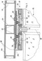
- FIG. 1 shows a first embodiment of the arrangement of a drive unit 10 on a ceiling element 11 of a revolving door.
- the ceiling element 11 is formed by metal profile elements, for example, which form a supporting basic structure in the ceiling area of the revolving door.
- a turnstile 12 is shown, which consists of two rotating wings 23, for example.
- An adapter element 13 is attached to the underside of the ceiling element 11.
- the attachment is shown as an example using angle elements 25, and the adapter element 13 is pot-shaped and has a collar-shaped peripheral edge 26.
- the base area 27 of the adapter element 13 forms a mounting opening on the ceiling of the revolving door that points downwards in the direction of the turnstile 12 and is delimited at the edge by the peripheral edge 26.
- the adapter element 13 can therefore be set up with the suspended ceiling elements 20 already below the ceiling element 11, so that for the subsequent installation of the drive unit 10, which is formed by an electronically commutated multi-pole motor 14, an installation opening is created which is delimited by the peripheral edge 26 and the base area 27 of the adapter element 13.
- the multi-pole motor 14 has a disk-shaped, flat extension and the installation opening for the multi-pole motor 14 is dimensioned by the adapter element 13 in such a way that the multi-pole motor 14 can be inserted into the installation opening.
- a fitter can arrange the multi-pole motor 14 on the adapter element 13 from the assembly direction 17, which coincides with the rotation axis 18 of the turnstile 12.
- the arrangement can initially comprise pre-fixing the multi-pole motor 14 on the adapter element 13, for which purpose pre-fixing means 15 are provided.
- the multi-pole motor 14 is shown in an arrangement latched to the pre-fixing means 15, and the pre-fixing means 15 have, for example, snap hooks that engage behind openings in the multi-pole motor 14 so that it can be pre-fixed securely in the adapter element 13 by a fitter overhead.
- adjustment means 19 arranged on the adapter element 13, which comprise elastic elements 28 and screw elements 29.
- the screw elements 29 of the adjustment means 19 can be adjusted by a fitter with a tool through tool openings 30 in the multi-pole motor 14, whereby the position of the multi-pole motor 14 changes relative to the adapter element 13.
- the multi-pole motor 14 can be aligned in its planar extension to the turnstile 12 so that the rotation axis 18 of the output shaft 31 of the multi-pole motor 14 can be aligned with the rotation axis 18 of the turnstile 12.
- the multi-pole motor 14 can be permanently fixed in the adjusted position to the adapter element 13 for later operation in the revolving door, but it is possible to already fix the multi-pole motor 14 by means of the arrangement by means of the Adjustment means 19 on the adapter element 13 to operate permanently.
- the associated advantage is an elastic suspension of the multi-pole motor 14 by the above-described design of the adjustment means 19, wherein in particular elastic receiving elements 32 are shown, which also enable a damping reception of the multi-pole motor 14 on the adapter element 13.
- the multi-pole motor 14 has a stator part 33 and a rotor part 34, and the stator part 33 is attached to the adapter element 13 via the adjustment means 19, wherein the rotary vanes 23 of the turnstile 12 are attached to the rotor part 34 in a manner not shown in detail.
- Coil elements 35 and magnetic elements 36 are located between the stator part 33 and the rotor part 34, and a torque can be generated between the rotor part 34 and the stator part 33 by means of a corresponding electronic commutation of the current supply to the coil elements 35.
- the magnetic elements 36 are located on the outside in relation to the coil elements 35, so that the multi-pole motor 14 has the design of an external rotor.
- the embodiment also shows a lighting device 21 which is ring-shaped and is arranged, for example, on the collar-shaped peripheral edge 26 of the adapter element 13. Due to the ring-shaped design of the lighting device 21, it encloses the multi-pole motor 14 and enables illumination of the accessible area of the revolving door.
- FIG. 2 shows a cross-sectional view of a further arrangement of a drive unit 10 on a ceiling element 16 of a revolving door.
- the ceiling element 16 has profile elements 37, on which cover plates 38 are arranged on the top and bottom sides, wherein at least the bottom side Cover plate 38 can already comprise a decorative surface, so that no further suspended ceiling elements have to be arranged on the ceiling element 16.
- An adapter element 22 is arranged on the underside of the lower cover plate 38 of the cover element 16 by means of fastening means 39, wherein the adapter element 22 is designed as a flat adapter disk.
- Pre-fixing means 24 protrude from the extension plane of the adapter element 22, which are designed as mushroom head elements and engage in receiving openings 40 in the multi-pole motor 14.
- the receiving openings 40 can be designed like a keyhole, so that the mushroom head of the pre-fixing means 24 initially fits through the opening, and when the multi-pole motor 14 is then rotated, the receiving openings 40 can engage behind the mushroom heads of the pre-fixing means 24 in a form-fitting manner, so that the multi-pole motor 14 can be attached to the adapter element 22 in a self-retaining manner by just one person without the use of a tool.
- adjustment means 19 can be attached, via which the multi-pole motor 14 can be aligned to the adapter element 22, in particular to establish the alignment of the output shaft 31 of the multi-pole motor 14 relative to the rotation axis 18 of the turnstile 12.
- the adjustment means 19 can also form fastening means, so that the multi-pole motor 14 is already set up for later operation in the revolving door via the adjustment means 19.
Landscapes
- Engineering & Computer Science (AREA)
- Civil Engineering (AREA)
- Structural Engineering (AREA)
- Power-Operated Mechanisms For Wings (AREA)
- Connection Of Motors, Electrical Generators, Mechanical Devices, And The Like (AREA)
- Extensible Doors And Revolving Doors (AREA)
Description
- Die vorliegende Erfindung betrifft eine Karusselltür und ein Verfahren zur Anordnung einer Antriebseinheit in einer Karusselltür, wobei die Antriebseinheit an einem Deckenelement der Karusselltür angeordnet wird und zum Antrieb eines Drehkreuzes der Karusselltür dient.
- Die
EP 2 072 737 A2 zeigt eine Anordnung einer Antriebseinheit in einer Karusselltür, wobei die Antriebseinheit an einem Deckenelement der Karusselltür angeordnet ist. Das Verfahren zur Anordnung umfasst dabei das Anbringen der Antriebseinheit, die aus einem Motor und einem Getriebe besteht, wobei die einzelnen Komponenten der Antriebseinheit nach Errichtung des Rahmens der Karusselltür und nach Einrichtung des Drehkreuzes in einen Einbauraum in der Decke der Karusselltür eingebaut werden. In der Regel befinden sich die Komponenten der Antriebseinheit oberhalb einer Deckenkonstruktion, die den Aufnahmeraum des Drehkreuzes in der Karusselltür oberseitig abschließt. Dadurch entstehen Nachteile in der Zugänglichkeit der Antriebseinheit, wodurch beispielsweise auch Wartungsarbeiten erschwert werden. Insbesondere dadurch, dass oberseitige Einbauten häufig der Witterung ausgesetzt sind, sind besondere Abdichtungsmaßnahmen erforderlich, ferner ergeben sich ästhetische Nachteile bei der Gestaltung der Karusselltür, da die Einbauhöhe konventioneller Antriebseinheiten im oder über einem Deckenelement der Karusselltür häufig 200 mm überschreitet. - Die
WO 2006/005438 A1 offenbart eine Karusselltür gemäß dem Oberbegriff des Anspruchs 1. - Der Erfindung liegt die Aufgabe zu Grunde, eine Karusselltür mit einer vereinfacht angeordneten Antriebseinheit und ein Verfahren zur vereinfachten Anordnung einer Antriebseinheit in einer Karusselltür zu schaffen, wobei die Antriebseinheit an einem Deckenelement der Karusselltür angeordnet werden soll.
- Diese Aufgabe wird ausgehend von einer Karusselltür bzw. einem Verfahren zur Anordnung einer Antriebseinheit in einer Karusselltür gemäß dem Stand der Technik mit den kennzeichnenden Merkmalen gelöst. Vorteilhafte Weiterbildungen der Erfindung sind in den abhängigen Ansprüchen angegeben.
- Die Erfindung schlägt ein Verfahren zur Anordnung einer Antriebseinheit in einer Karusselltür vor, wobei die Antriebseinheit an einem Deckenelement der Karusselltür angeordnet wird und zum Antrieb eines Drehkreuzes der Karusselltür dient, wenigstens umfassend den Schritt des Anbringens eines Adapterelementes an das Deckenelement, den Schritt des Anordnens eines elektronisch kommutierten Vielpolmotors an einem Adapterelement und des Einjustierens des Vielpolmotors relativ zum Drehkreuz der Karusselltür mittels des Adapterelementes.
- Elektronisch kommutierte Vielpolmotoren können getriebelos mit dem Drehkreuz der Karusselltür verbunden werden und durch eine flache, scheibenförmige Bauart in einfacher Weise an einem Deckenelement einer Karusselltür angeordnet werden. Durch die scheibenförmige Grundstruktur des Vielpolmotors entsteht eine Art Drehteller, der sich auf vorteilhafte Weise unterseitig am Deckenelement anordnen lässt und folglich zwischen dem Deckenelement und dem Drehkreuz der Karusselltür einsitzen kann. Somit kann der Vielpolmotor zugleich zur deckenseitigen Lagerung des Drehkreuzes dienen.
- Vielpolmotoren sind auch unter der Bezeichnung der Torquemotoren bekannt und weisen grundsätzlich auf einer Kreisbahn angeordnete Spulenelemente auf, die ebenfalls auf einer Kreisbahn angeordneten Magnetelementen gegenüberstehen, beispielsweise innenseitig, außenseitig oder axial gegenüberstehend, sodass ein hochpoliger, drehmomentstarker Direktantrieb gebildet wird.
- Vielpolmotoren können einen Rotorteil und einen Statorteil besitzen, wobei der Statorteil ruhend am Adapterelement angeordnet werden kann, wonach der Rotorteil mit dem Drehkreuz der Karusselltür verbunden werden kann. Der Rotorteil und der Statorteil können jeweils einen planen, flach ausgeführten Abschnitt aufweisen, wobei sich die Abschnitte planparallel gegenüberstehen. Der Rotorteil und/oder der Statorteil kann dabei scheibenförmig und/oder topfförmig ausgestaltet sein.
- Durch die erfindungsgemäße Anordnung eines Adapterelementes zwischen dem Vielpolmotor und dem Deckenelement entsteht der Vorteil, dass der Vielpolmotor am Deckenelement auf vereinfachte Weise einjustiert werden kann, um relativ zum Drehkreuz der Karusselltür ausgerichtet zu werden. Das Adapterelement bildet eine Aufnahmeeinheit zur einfachen Montage, Justierung und Ausrichtung des scheibenförmigen, getriebelosen Vielpolmotors, der die Antriebseinheit für die Karusselltür bildet. Durch das Adapterelement kann die Antriebseinheit überdies schneller montiert und auch demontiert werden, wobei zudem eine komfortable und präzise Ausrichtung des Vielpolmotors möglich ist.
- Mit besonderem Vorteil ergibt sich eine Aufnahmeeinheit für den Vielpolmotor, die eine nach unten gerichtete Öffnung oder Montagefläche aufweist, die insbesondere in Richtung zum Drehkreuz der Karusselltür weist. Die Öffnung oder die Montagefläche ist dabei groß genug, sodass sich durch die Öffnung an die Montagefläche der Vielpolmotor ohne Ausbau oder Demontage von weiteren Komponenten der Karusselltür montieren lässt. Insbesondere kann die Deckenkonstruktion der Karusselltür bereits vervollständigt sein, und erst anschließend kann der Vielpolmotor in der Öffnung in der Decke eingesetzt werden.
- Der Schritt des Anbringens des Adapterelementes an das Deckenelement erfolgt von der Unterseite an das Deckenelement, und der Schritt des Anordnens des elektronisch kommutierten Vielpolmotors erfolgt ebenfalls unterseitig am Adapterelement. Daraus ergibt sich der Vorteil, dass die Antriebseinheit vollständig unterhalb der lasttragenden Teile der Karusselltür angeordnet werden kann. Durch die Anordnung unterhalb der tragenden Elemente der Deckenkonstruktion der Karusselltür muss der für die Antriebseinheit notwendige Bauraum bei der Gestaltung der Deckenkonstruktion nicht berücksichtigt werden und die Ausführungsart der Deckenkonstruktion ist lediglich von untergeordneter Bedeutung und muss nicht an die Anordnung der Antriebseinheit angepasst werden. Hierdurch ist es möglich, die technische Gestaltung der Deckenkonstruktion zu vereinfachen und Herstellkosten sowie Montageaufwand zu senken. Außerdem kann mit dem erfindungsgemäßen Verfahren zur Anordnung der Antriebseinheit eine Nachrüstung von Karusselltüren erfolgen, und die platzsparende Anordnung des Vielpolmotors unterhalb des Deckenelementes mittels des Adapterelementes kann in bestehende Konstruktionen sehr einfach adaptiert werden, da keine Rücksicht auf einen innerhalb der Deckenkonstruktion zur Verfügung stehender Bauraum genommen werden muss.
- Das Einjustieren des Vielpolmotors kann in einer oder mehreren Raumrichtungen und Winkelstellungen erfolgen, insbesondere kann die Abtriebsachse des Vielpolmotors an der Rotationsachse des Drehkreuzes ausgerichtet werden.
- Nach dem Schritt des Einjustierens des Vielpolmotors relativ zum Drehkreuz der Karusselltür mittels des Adapterelementes kann der Schritt des endgültigen Fixierens des Vielpolmotors am Adapterelement erfolgen, wenn das Einjustieren zwischen dem Vielpolmotor und dem Adapterelement ausgeführt wurde. Auch besteht die Möglichkeit, dass das Einjustieren des Vielpolmotors relativ zum Drehkreuz der Karusselltür zwischen dem Adapterelement und dem Deckenelement erfolgt, während der Vielpolmotor am Adapterelement starr angeordnet wird. Unabhängig von der Ausführungsform der Einjustage des Vielpolmotors relativ zum Drehkreuz kann abschließend der Schritt folgen, den Vielpolmotor auch relativ zum Deckenelement starr anzuordnen, indem der Vielpolmotor durch entsprechende Befestigungsmittel endgültig am Deckenelement fixiert wird. Damit wird der Vorteil erreicht, dass sich der Vielpolmotor auch im Betrieb der Karusselltür nicht von selbst durch Vibrationen der Antriebseinheit verstellen kann, da der Vielpolmotor am Deckenelement durch entsprechende Befestigungsmittel festgesetzt wurde.
- Nach einer vorteilhaften Weiterbildung des Verfahrens kann dieses durch den Schritt des getriebelosen Verbindens des elektronisch kommutierten Vielpolmotors mit dem Drehkreuz der Karusselltür ergänzt sein, insbesondere mit den Drehflügeln des Drehkreuzes. Ist der Vielpolmotor relativ zum Drehkreuz ausgerichtet, welches sich ohne direkte Verbindung zum Vielpolmotor bereits im Rahmen der Karusselltür befinden kann, so kann nach Einjustage des Vielpolmotors die Verbindung mit den Drehflügeln des Drehkreuzes hergestellt werden. Beispielsweise können die Drehflügel des Drehkreuzes mit dem Rotorteil des Vielpolmotors durch eine Verschraubung verbunden werden.
- Das Verfahren kann weiterhin gekennzeichnet sein durch den Schritt der Vormontage des Vielpolmotors an das Adapterelement durch entsprechende Vorfixiermittel, wenn das Adapterelement bereits am Deckenelement angeordnet wurde. Durch die Vorfixiermittel wird es ermöglicht, die Antriebseinheit vor der endgültigen Montage, Einjustierung und Fixierung zunächst auf einfache Art vorzupositionieren beziehungsweise vorzufixieren. Dies kann zum Beispiel durch Einhängung, durch eine Einrastung oder durch einen Bajonettverschluss erfolgen. Die Vorfixiermittel können federbelastete Schnapphaken umfassen, die durch Öffnungen in der Antriebseinheit hindurchgeführt werden, und um die Antriebseinheit formschlüssig am Adapterelement halten können. Auch ist es möglich, die Vorfixiermittel durch Pilzkopfelemente zu bilden, die in schlüssellochförmige Öffnungen in der Antriebseinheit hindurchgeführt werden können, und wird die Antriebseinheit unter leichter Winkeldrehung verdreht, kann diese durch die Pilzkopfelemente bereits gehalten werden. Ein besonderer Vorteil derartiger Vorfixiermittel ist darin gegeben, dass das Verfahren des Vorfixierens ohne Werkzeug erfolgen kann, und sodass das Vorfixieren durch eine einzelne Person in Überkopfmontage ausgeführt werden kann. Ein weiterer Vorteil wird dadurch erreicht, dass das Adapterelement und der Vielpolmotor aus einer gemeinsamen Montagerichtung an das Deckenelement montiert wird, insbesondere wobei die Montageeinrichtung mit der Rotationsachse des Drehkreuzes zusammenfällt. Das Adapterelement und der Vielpolmotor sind von unten an das Deckenelement montiert, sodass die Montage aus dem Raum heraus erfolgt, in dem anschließend das Drehkreuz eingesetzt wird und rotieren kann. Beispielsweise kann der Vielpolmotor vorfixiert werden, um anschließend das Drehkreuz in den Rahmen der Karusselltür einzusetzen. Anschließend erfolgt die Einjustage des Vielpolmotors relativ zum Drehkreuz, um schließlich in einem letzten Schritt den Vielpolmotor mit dem Drehkreuz in Verbindung zu bringen. Eine Einjustage des Vielpolmotors kann dabei auch ohne bereits eingebrachtes Drehkreuz in den Rahmen der Karusselltür erfolgen, beispielsweise kann die Rotationsachse des Drehkreuzes durch ein Lot bekannt sein, sodass die Einjustage des Vielpolmotors an der Rotationsachse des Drehkreuzes ausgerichtet wird, ohne dass das Drehkreuz selbst schon im Rahmen der Karusselltür eingesetzt ist sein muss. Alternativ kann das Verfahren jedoch vorsehen, vor dem Einjustieren des Vielpolmotors am Deckenelement durch das Adapterelement das Drehkreuz bereits am Vielpolmotor beispielsweise bewegbar anzuordnen, und die Verbindung zwischen dem Vielpolmotor zum Drehkreuz erst nach der Einjustierung endgültig für den späteren Betrieb einzurichten.
- Das Adapterelement weist wenigstens ein Justagemittel auf, wobei das Einjustieren der Antriebseinheit relativ zum Drehkreuz der Karusselltür durch ein, jedoch vorzugsweise durch zwei oder mehr Justagemittel erfolgt. Die Justagemittel können beispielsweise durch gummielastische Elemente gebildet werden, die in Verbindung mit jeweils einem Schraubelement verschieden stark elastisch verformt werden können. Alternativ zu gummielastischen Elementen können auch Federelemente, beispielsweise Spiralfedern oder Schraubenfedern, Anwendung finden. Insbesondere wird ein weiterer Vorteil dadurch erreicht, dass die Justagemittel mit den Vorfixiermitteln baueinheitlich ausgeführt werden, sodass die Vorfixiermittel auch durch die Justagemittel gebildet werden können. Beispielsweise können die Justagemittel Schnapphaken umfassen oder durch Pilzkopfelemente ergänzt sein, und der Vielpolmotor kann somit an die Justagemittel vorfixiert werden, und anschließend kann der Vielpolmotor durch die Justagemittel justiert werden. Schließlich können die Justagemittel noch zur endgültigen Fixierung des Vielpolmotors am Adapterelement dienen.
- Das Verfahren kann schließlich gekennzeichnet sein durch den Schritt des Anordnens von wenigstens einem Unterdeckenelement am Adapterelement. Das Adapterelement kann topfartig oder scheibenartig ausgeführt sein, und insbesondere bei einer topfartigen Ausführung kann ein außenseitig umlaufender Kragen des Adapterelementes vorgesehen sein, in oder an dem die Unterdeckenelemente eingehängt werden.
- Die vorliegende Erfindung richtet sich ferner auf eine Karusselltür, die mit dem vorbeschriebenen Verfahren gebildet wird. Die Erfindung richtet sich dabei auf eine Antriebseinheit in einer Karusselltür, wobei die Karusselltür ein Deckenelement aufweist, an dem die Antriebseinheit angeordnet ist und zum Antrieb eines Drehkreuzes der Karusselltür mit diesem verbunden ist, wobei die Antriebseinheit einen elektronisch kommutierten Vielpolmotor umfasst, der mit einem Adapterelement am Deckenelement angeordnet ist und mit dem Drehkreuz getriebelos verbunden ist, wobei das Adapterelement zur Einjustage des Vielpolmotors relativ zum Drehkreuz der Karusselltür ausgebildet ist. Die in Zusammenhang mit dem Verfahren vorbeschriebenen Merkmale und Vorteile der Anordnung der Antriebseinheit in der Karusselltür mittels des Adapterelementes finden für die Anordnung der Antriebseinheit ebenfalls Berücksichtigung.
- Insbesondere kann das Adapterelement wenigstens ein Vorfixiermittel aufweisen, mit dem der Vielpolmotor am Adapterelement vorfixierbar ist. Auch weist das Adapterelement wenigstens ein Justagemittel auf, das zum Einjustieren der Antriebseinheit relativ zum Drehkreuz der Karusselltür dient. Das Justagemittel kann dabei derart ausgeführt sein, dass eine Einjustage des Vielpolmotors relativ zum Adapterelement ermöglicht ist, oder das Justagemittel ist derart ausgeführt, dass das Adapterelement relativ zum Deckenelement einjustiert werden kann, während der Vielpolmotor am Adapterelement starr angeordnet ist.
- Mit weiterem Vorteil kann am Adapterelement wenigstens ein Unterdeckenelement angeordnet werden, hierfür kann das Adapterelement entsprechende Mittel zur Aufnahme von Unterdeckenelementen aufweisen. Insbesondere kann das Adapterelement topfförmig ausgeführt sein und einen Kragen aufweisen, wobei das wenigstens eine Unterdeckenelement hinter den Kragen eingehängt werden kann.
- Es ist zudem eine Beleuchtungseinrichtung vorgesehen sein, die am Adapterelement und/oder am Vielpolmotor selbst angeordnet ist. Die Beleuchtungseinrichtung ist so ausgeführt, dass diese den Vielpolmotor ringförmig umschließt. Somit kann eine Beleuchtung des begehbaren Bereiches innerhalb des Drehkreuzes der Karusselltür gebildet werden, und die ringförmig ausgebildete Beleuchtungseinrichtung kann den Bereich um die Rotationsachse des Drehkreuzes vollumfänglich ausleuchten.
- Weitere, die Erfindung verbessernde Maßnahmen werden nachstehend gemeinsam mit der Beschreibung eines bevorzugten Ausführungsbeispiels der Erfindung anhand der Figuren näher dargestellt. Es zeigt:
- Figur 1
- ein Ausführungsbeispiel einer Anordnung einer Antriebseinheit an einem Deckenelement einer Karusselltür mit einem Adapterelement gemäß einer ersten Ausführungsvariante und
- Figur 2
- ein nicht erfindungsgemäßes Ausführungsbeispiel einer Anordnung einer Antriebseinheit an einem Deckenelement einer Karusselltür mit einem Adapterelement gemäß einer weiteren Ausführungsvariante.
-
Figur 1 zeigt ein erstes Ausführungsbeispiel der Anordnung einer Antriebseinheit 10 an einem Deckenelement 11 einer Karusselltür. Das Deckenelement 11 ist beispielhaft durch metallische Profilelemente gebildet, die eine tragende Grundstruktur im Deckenbereich der Karusselltür bilden. Unterhalb des Deckenelementes 11 ist ein Drehkreuz 12 gezeigt, das aus beispielhaft zwei Drehflügeln 23 besteht. - An der Unterseite des Deckenelementes 11 ist ein Adapterelement 13 befestigt. Die Befestigung ist beispielhaft über Winkelelemente 25 gezeigt, und das Adapterelement 13 ist topfförmig ausgebildet und besitzt einen kragenförmig umlaufenden Rand 26. Der Bodenbereich 27 des Adapterelementes 13 bildet eine nach unten, in Richtung zum Drehkreuz 12 weisende Einbauöffnung an der Decke der Karusselltür, die randseitig durch den umlaufenden Rand 26 begrenzt ist.
- Auf der Unterseite des Deckenelementes 11 befinden sich Unterdeckenelemente 20, die in den kragenförmig umlaufenden Rand 26 eingehängt sind und beispielsweise einen Sichtschutz zum Deckenelement 11 bilden. Das Adapterelement 13 kann folglich mit den Unterdeckenelementen 20 bereits unterhalb des Deckenelementes 11 eingerichtet werden, sodass sich zum nachfolgenden Einbau der Antriebseinheit 10, die durch einen elektronisch kommutierten Vielpolmotor 14 gebildet ist, eine Einbauöffnung ergibt, die durch den umlaufenden Rand 26 und dem Bodenbereich 27 des Adapterelementes 13 begrenzt ist.
- Der Vielpolmotor 14 weist eine scheibenförmige, flache Erstreckung auf und die Einbauöffnung für den Vielpolmotor 14 ist durch das Adapterelement 13 derart bemaßt, dass der Vielpolmotor 14 in die Einbauöffnung einsetzbar ist. Hierfür kann ein Monteur den Vielpolmotor 14 aus der Montagerichtung 17, die mit der Rotationsachse 18 des Drehkreuzes 12 zusammenfällt, an das Adapterelement 13 anordnen. Die Anordnung kann zunächst ein Vorfixieren des Vielpolmotors 14 am Adapterelement 13 umfassen, wozu Vorfixiermittel 15 vorgesehen sind. Der Vielpolmotor 14 ist in einer an den Vorfixiermitteln 15 verrasteten Anordnung gezeigt, und die Vorfixiermittel 15 besitzen beispielhaft Schnapphaken, die Öffnungen im Vielpolmotor 14 hintergreifen, sodass dieser sicher haltend durch eine Monteur über Kopf im Adapterelement 13 vorfixiert werden kann.
- Zwischen dem Vielpolmotor 14 und dem Adapterelement 13 befinden sich am Adapterelement 13 angeordnete Justagemittel 19, die elastische Elemente 28 sowie Schraubelemente 29 umfassen.
- Nach dem Vorfixieren des Vielpolmotors 14 an den Vorfixiermitteln 15 können die Schraubelemente 29 der Justagemittel 19 durch Werkzeugöffnungen 30 im Vielpolmotor 14 durch einen Monteur mit einem Werkzeug verstellt werden, wodurch sich die Lage des Vielpolmotors 14 relativ zum Adapterelement 13 ändert. Insbesondere kann der Vielpolmotor 14 in seiner flächigen Erstreckung zum Drehkreuz 12 ausgerichtet werden, sodass die Rotationsachse 18 der Abtriebswelle 31 des Vielpolmotors 14 mit der Rotationsachse 18 des Drehkreuzes 12 fluchten kann.
- Durch nicht weiter gezeigte weitere Befestigungsmittel kann der Vielpolmotor 14 in der einjustierten Lage endgültig am Adapterelement 13 für den späteren Betrieb in der Karusselltür festgesetzt werden, jedoch besteht die Möglichkeit, den Vielpolmotor 14 bereits durch die Anordnung mittels der Justagemittel 19 am Adapterelement 13 dauerhaft zu betreiben. Der damit einhergehende Vorteil ist eine elastische Aufhängung des Vielpolmotors 14 durch die vorstehend beschriebene Ausführung der Justagemittel 19, wobei insbesondere elastische Aufnahmeelemente 32 gezeigt sind, die ebenfalls eine dämpfende Aufnahme des Vielpolmotors 14 am Adapterelement 13 ermöglichen.
- Der Vielpolmotor 14 weist einen Statorteil 33 und einen Rotorteil 34 auf, und der Statorteil 33 ist über die Justagemittel 19 am Adapterelement 13 befestigt, wobei auf nicht näher gezeigte Weise die Drehflügel 23 des Drehkreuzes 12 am Rotorteil 34 befestigt sind. Zwischen dem Statorteil 33 und dem Rotorteil 34 befinden sich Spulenelemente 35 sowie Magnetelemente 36, und durch eine entsprechende elektronische Kommutierung der Bestromung der Spulenelemente 35 kann ein Drehmoment zwischen dem Rotorteil 34 und dem Statorteil 33 erzeugt werden. Die Magnetelemente 36 befinden sich dabei in Bezug auf die Spulenelemente 35 auf der Außenseite, sodass der Vielpolmotor 14 die Bauart eines Außenläufers besitzt.
- Das Ausführungsbeispiel zeigt weiterhin eine Beleuchtungseinrichtung 21, die ringförmig ausgebildet ist und am kragenförmig umlaufenden Rand 26 des Adapterelementes 13 beispielhaft angeordnet ist. Durch die ringförmige Ausbildung der Beleuchtungseinrichtung 21 umschließt diese den Vielpolmotor 14 und ermöglicht eine Illuminierung des begehbaren Bereiches der Karusselltür.
-
Figur 2 zeigt in einer Querschnittsansicht eine weitere Anordnung einer Antriebseinheit 10 an einem Deckenelement 16 einer Karusselltür. Das Deckenelement 16 weist Profilelemente 37 auf, an die oberseitig und unterseitig Deckplatten 38 angeordnet sind, wobei zumindest die unterseitige Deckplatte 38 bereits eine Dekoroberfläche umfassen kann, sodass keine weiteren Unterdeckenelemente an dem Deckenelement 16 angeordnet werden müssen. - Auf der Unterseite der unteren Deckplatte 38 des Deckenelementes 16 ist durch Befestigungsmittel 39 ein Adapterelement 22 angeordnet, wobei das Adapterelement 22 als plan ausgebildete Adapterscheibe ausgeführt ist. Aus der Erstreckungsebene des Adapterelementes 22 ragen Vorfixiermittel 24 hervor, die als Pilzkopfelemente ausgeführt sind und in Aufnahmeöffnungen 40 im Vielpolmotor 14 eingreifen. Die Aufnahmeöffnungen 40 können schlüssellochartig ausgebildet sein, sodass zunächst der Pilzkopf der Vorfixiermittel 24 durch die Öffnung passt, und bei anschließender Verdrehung des Vielpolmotors 14 können die Aufnahmeöffnungen 40 die Pilzköpfe der Vorfixiermittel 24 formschlüssig hintergreifen, sodass der Vielpolmotor 14 ohne Verwendung eines Werkzeugs durch nur eine Person selbsthaltend am Adapterelement 22 angebracht werden kann.
- Nach Vorfixierung des Vielpolmotors 14 am Adapterelement 22 können Justagemittel 19 angebracht werden, über die der Vielpolmotor 14 am Adapterelement 22 ausgerichtet werden kann, um insbesondere die Fluchtung der Abtriebswelle 31 des Vielpolmotors 14 relativ zur Rotationsachse 18 des Drehkreuzes 12 herzustellen. Dabei können die Justagemittel 19 zugleich Befestigungsmittel bilden, sodass über die Justagemittel 19 der Vielpolmotor 14 bereits für den späteren Betrieb in der Karusselltür eingerichtet ist.
- Die Erfindung, die durch die nachfolgenden Ansprüche definiert ist, beschränkt sich in ihrer Ausführung nicht auf das vorstehend angegebene bevorzugte Ausführungsbeispiel.
-
- 10
- Antriebseinheit
- 11
- Deckenelement
- 12
- Drehkreuz
- 13
- Adapterelement
- 14
- Vielpolmotor
- 15
- Vorfixiermittel
- 16
- Deckenelement
- 17
- Montagerichtung
- 18
- Rotationsachse
- 19
- Justagemittel
- 20
- Unterdeckenelement
- 21
- Beleuchtungseinrichtung
- 22
- Adapterelement
- 23
- Drehflügel
- 24
- Vorfixiermittel
- 25
- Winkelelement
- 26
- kragenförmig umlaufender Rand
- 27
- Bodenbereich
- 28
- elastisches Element
- 29
- Schraubelement
- 30
- Werkzeugöffnung
- 31
- Abtriebswelle
- 32
- elastisches Aufnahmeelement
- 33
- Statorteil
- 34
- Rotorteil
- 35
- Spulenelement
- 36
- Magnetelement
- 37
- Profilelement
- 38
- Deckplatten
- 39
- Befestigungsmittel
- 40
- Aufnahmeöffnung
Claims (8)
- Karusselltür mit einer Antriebseinheit (10), wobei die Karusselltür ein Deckenelement (11, 16) aufweist, an dem die Antriebseinheit (10) angeordnet ist und zum Antrieb eines Drehkreuzes (12) der Karusselltür mit diesem verbunden ist, wobei die Antriebseinheit (10) einen elektronisch kommutierten Vielpolmotor (14) umfasst, der mit einem Adapterelement (13, 22) am Deckenelement (11, 16) angeordnet ist und mit dem Drehkreuz (12) getriebelos verbunden ist, dadurch gekennzeichnet, dass das Adapterelement (13, 22) zur Einjustage des Vielpolmotors (14) relativ zum Drehkreuz (12) der Karusselltür ausgebildet ist, indem das Adapterelement (13, 22) unterseitig am Deckenelement (11, 16) angeordnet und der Vielpolmotor (14) unterseitig am Adapterelement (13, 22) angeordnet sind und wobei das Adapterelement (13, 22) wenigstens ein Justagemittel (19) aufweist, das zum Einjustieren der Antriebseinheit (10) relativ zum Drehkreuz (12) der Karusselltür dient, wobei am Adapterelement (13) und/oder am Vielpolmotor (14) eine Beleuchtungseinrichtung (21) angeordnet ist, die den Vielpolmotor (14) ringförmig umschließt.
- Anordnung nach Anspruch 1, dadurch gekennzeichnet, dass das Adapterelement (13, 22) wenigstens ein Vorfixiermittel (15, 24) aufweist, mit dem der Vielpolmotor (14) am Adapterelement (13) vorfixierbar ist.
- Anordnung nach Anspruch 1 oder 2, dadurch gekennzeichnet, dass am Adapterelement (13) wenigstens ein Unterdeckenelement (20) angeordnet ist.
- Verfahren zur Anordnung einer Antriebseinheit (10) in einer Karusselltür gemäß einem der Ansprüche 1 bis 3, wobei die Antriebseinheit (10) an einem Deckenelement (11, 16) der Karusselltür angeordnet wird und zum Antrieb eines Drehkreuzes (12) der Karusselltür dient, wenigstens umfassend die folgenden Schritte:- Anbringen eines Adapterelementes (13, 22) an das Deckenelement (11, 16), wobei das Adapterelement (13, 22) Justagemittel (19) aufweist,- Anordnen eines elektronisch kommutierten Vielpolmotors (14) an dem Adapterelement (13, 22),- indem das Adapterelement (13, 22) unterseitig am Deckenelement (11, 16) angeordnet und der Vielpolmotor (14) unterseitig am Adapterelement (13, 22) angeordnet wird und- Einjustieren des Vielpolmotors (14) relativ zum Drehkreuz (12) der Karusselltür mittels des Adapterelementes (13, 22), wobei das Einjustieren der Antriebseinheit (10) relativ zum Drehkreuz (12) der Karusselltür durch zwei oder mehr Justagemittel (19) erfolgt.
- Verfahren nach Anspruch 4, gekennzeichnet durch den Schritt des getriebelosen Verbindens des elektronisch kommutierten Vielpolmotors (14) mit dem Drehkreuz (12) der Karusselltür, insbesondere mit Drehflügeln (23) des Drehkreuzes (12).
- Verfahren nach Anspruch 4 oder 5, gekennzeichnet durch den Schritt der Vormontage des Vielpolmotors (14) an das Adapterelement (13, 22) durch Vorfixiermittel (15, 24).
- Verfahren nach einem der Ansprüche 4 bis 6, dadurch gekennzeichnet, dass das Adapterelement (13, 22) und der Vielpolmotor (14) aus einer gemeinsamen Montagerichtung (17) an das Deckenelement (11, 16) montiert werden, insbesondere wobei die Montagerichtung (17) mit der Rotationsachse (18) des Drehkreuzes (12) zusammenfällt.
- Verfahren nach einem der vorgenannten Ansprüche 4 bis 7, gekennzeichnet durch den Schritt des Anordnens von wenigstens einem Unterdeckenelement (20) am Adapterelement (13).
Applications Claiming Priority (1)
| Application Number | Priority Date | Filing Date | Title |
|---|---|---|---|
| DE102013000416.0A DE102013000416B4 (de) | 2013-01-14 | 2013-01-14 | Verfahren zur Anordnung einer Antriebseinheit in einer Karusselltür |
Publications (4)
| Publication Number | Publication Date |
|---|---|
| EP2754821A2 EP2754821A2 (de) | 2014-07-16 |
| EP2754821A3 EP2754821A3 (de) | 2017-07-19 |
| EP2754821B1 true EP2754821B1 (de) | 2025-03-05 |
| EP2754821C0 EP2754821C0 (de) | 2025-03-05 |
Family
ID=49917552
Family Applications (1)
| Application Number | Title | Priority Date | Filing Date |
|---|---|---|---|
| EP14000023.3A Active EP2754821B1 (de) | 2013-01-14 | 2014-01-06 | Karusseltür und verfahren zur anordnung einer antriebseinheit in einer karusseltür |
Country Status (4)
| Country | Link |
|---|---|
| US (1) | US9157266B2 (de) |
| EP (1) | EP2754821B1 (de) |
| CN (1) | CN103924863B (de) |
| DE (1) | DE102013000416B4 (de) |
Families Citing this family (9)
| Publication number | Priority date | Publication date | Assignee | Title |
|---|---|---|---|---|
| EP3034759A1 (de) * | 2014-12-16 | 2016-06-22 | DORMA Deutschland GmbH | Verfahren zur Steuerung einer Karusselltür |
| EP3034758A1 (de) * | 2014-12-16 | 2016-06-22 | DORMA Deutschland GmbH | Karusselltür |
| EP3034760B1 (de) * | 2014-12-17 | 2018-06-27 | dormakaba Deutschland GmbH | Karusselltüranordnung |
| DE102015008133A1 (de) | 2015-06-24 | 2016-12-29 | Landert Motoren Ag | Antriebseinheit für eine automatische Karusselltür |
| EP4107353B1 (de) * | 2020-02-18 | 2025-09-03 | ASSA ABLOY Entrance Systems AB | Drehtür-montageanordnung |
| WO2021175968A1 (en) * | 2020-03-05 | 2021-09-10 | Assa Abloy Entrance Systems Ab | Revolving door assembly |
| DE102020117345A1 (de) | 2020-07-01 | 2022-01-05 | Dormakaba Deutschland Gmbh | Karusselltür mit lichtsignalfunktion |
| DE102020117346A1 (de) | 2020-07-01 | 2022-01-05 | Dormakaba Deutschland Gmbh | Karusselltür mit lichtsignalfunktion |
| EP4306759A1 (de) | 2022-07-11 | 2024-01-17 | dormakaba Deutschland GmbH | Karusselltür |
Citations (2)
| Publication number | Priority date | Publication date | Assignee | Title |
|---|---|---|---|---|
| DE10300645B3 (de) * | 2003-01-09 | 2005-01-13 | Dorma Gmbh + Co. Kg | Karusselltür |
| US20120005961A1 (en) * | 2010-06-17 | 2012-01-12 | Dorma Gmbh + Co. Kg | Revolving Door |
Family Cites Families (38)
| Publication number | Priority date | Publication date | Assignee | Title |
|---|---|---|---|---|
| US2007213A (en) * | 1932-01-07 | 1935-07-09 | Gen Bronze Corp | Revolving door |
| US2050584A (en) * | 1932-02-10 | 1936-08-11 | Gen Bronze Corp | Revolving door |
| US2119550A (en) * | 1934-07-19 | 1938-06-07 | Matthew H Loughridge | Speed control and braking system |
| US2136323A (en) * | 1938-04-28 | 1938-11-08 | Internat Door Company | Illumination means for revolving doors |
| US2186385A (en) * | 1939-05-08 | 1940-01-09 | Lockart Andrew | Emergency lock for revolving doors |
| US2341545A (en) * | 1940-11-06 | 1944-02-15 | Int Steel Co | Electrically controlled operating system for revolving doors |
| US2523980A (en) * | 1948-03-23 | 1950-09-26 | Whiteford Frederick Carter | Revolving door |
| US3364620A (en) * | 1965-07-29 | 1968-01-23 | Gen Bronze Corp | Revolving doors |
| US3349876A (en) * | 1967-03-06 | 1967-10-31 | Int Steel Co | Revolving door operating mechanism and speed controller |
| CA928150A (en) * | 1971-02-18 | 1973-06-12 | C. J. Rush Architectural Metal Limited | Revolving door |
| US3766686A (en) * | 1971-12-21 | 1973-10-23 | Int Steel Co | Revolving door operating and speed control mechanism |
| US3897651A (en) * | 1973-10-19 | 1975-08-05 | Int Steel Co | Revolving door speed control and hanger mechanism |
| US4332108A (en) * | 1979-12-03 | 1982-06-01 | C. J. Rush Limited | Collapsible revolving door |
| US4341165A (en) * | 1980-05-29 | 1982-07-27 | Calandritti R | Security system including a revolving door |
| US4358909A (en) * | 1980-07-24 | 1982-11-16 | Trikilis Emmanuel M | Turnstile |
| US4458447A (en) * | 1982-05-04 | 1984-07-10 | Heise Manufacturing Co., Inc. | Revolving door system |
| SE451865B (sv) * | 1982-11-05 | 1987-11-02 | Sandling Kjell Harry Med | Anordning vid karuselldorrar |
| US4627193A (en) * | 1983-09-20 | 1986-12-09 | Milan Schwarz | Revolving door control system |
| CA1239312A (en) * | 1984-07-27 | 1988-07-19 | Dennis Lowe | Revolving door |
| CA1266877A (en) * | 1984-09-13 | 1990-03-20 | Erich Rabe | Electronically commutated dc machine and use thereof |
| US4874975A (en) * | 1984-11-13 | 1989-10-17 | Digital Equipment Corporation | Brushless DC motor |
| US4976065A (en) * | 1989-11-20 | 1990-12-11 | Bc Research And Development, Inc. | Control apparatus for doors |
| US4970825A (en) * | 1990-03-14 | 1990-11-20 | Crane Fulview Door Company | Collapsing mechanism for revolving doors |
| US5191618A (en) * | 1990-12-20 | 1993-03-02 | Hisey Bradner L | Rotary low-frequency sound reproducing apparatus and method |
| DE4310295A1 (de) * | 1993-03-30 | 1994-10-06 | Tuerautomation Fehraltorf Ag F | Karusselltür |
| DE4429893C1 (de) * | 1994-08-25 | 1996-02-29 | Dorma Gmbh & Co Kg | Antriebsvorrichtung für eine Karusselltür |
| DE19836391C2 (de) * | 1998-08-12 | 2000-08-31 | Dorma Gmbh & Co Kg | Karusselltür |
| DE10318159A1 (de) * | 2003-04-17 | 2004-11-25 | Dorma Gmbh + Co. Kg | Karusselltür |
| DE102004033304B4 (de) * | 2004-07-08 | 2008-04-17 | Dorma Gmbh + Co. Kg | Karusselltür |
| DE102006040232A1 (de) * | 2006-08-28 | 2008-03-13 | Siemens Ag | Türantrieb für eine automatische Tür |
| US20080244978A1 (en) * | 2007-04-05 | 2008-10-09 | Rahmi Soyugenc | Motorized security revolving door |
| US8136297B2 (en) * | 2007-09-28 | 2012-03-20 | Babcock & Wilcox Technical Services Y-12, Llc | Speed control system for an access gate |
| DE102007062515C5 (de) * | 2007-12-20 | 2020-06-25 | Geze Gmbh | Automatische Karusselltüranlage und Verfahren zumBetrieb einer automatischen Karusselltüranlage |
| US7816875B2 (en) * | 2008-01-24 | 2010-10-19 | Viking Access Systems, Llc | High torque gearless actuation at low speeds for swing gate, roll-up gate, slide gate, and vehicular barrier operators |
| US20090188166A1 (en) * | 2008-01-24 | 2009-07-30 | Hassan Taheri | System for gearless operation of a movable barrier utilizing lorentz forces |
| US7816879B2 (en) * | 2008-02-19 | 2010-10-19 | Viking Access Systems, Llc | High torque movable barrier actuation at low speeds utilizing a hub motor |
| CN201401110Y (zh) * | 2009-04-13 | 2010-02-10 | 沙崇跃 | 磁悬浮自动旋转门 |
| DE202011000459U1 (de) * | 2011-03-01 | 2012-06-04 | GU Automatik GmbH | Einrichtung im Durchgangsbereich eines Gebäudes oder dergleichen |
-
2013
- 2013-01-14 DE DE102013000416.0A patent/DE102013000416B4/de active Active
-
2014
- 2014-01-06 EP EP14000023.3A patent/EP2754821B1/de active Active
- 2014-01-13 US US14/153,909 patent/US9157266B2/en active Active
- 2014-01-14 CN CN201410016425.1A patent/CN103924863B/zh active Active
Patent Citations (2)
| Publication number | Priority date | Publication date | Assignee | Title |
|---|---|---|---|---|
| DE10300645B3 (de) * | 2003-01-09 | 2005-01-13 | Dorma Gmbh + Co. Kg | Karusselltür |
| US20120005961A1 (en) * | 2010-06-17 | 2012-01-12 | Dorma Gmbh + Co. Kg | Revolving Door |
Also Published As
| Publication number | Publication date |
|---|---|
| EP2754821A2 (de) | 2014-07-16 |
| CN103924863A (zh) | 2014-07-16 |
| DE102013000416A1 (de) | 2014-07-17 |
| US20140196375A1 (en) | 2014-07-17 |
| DE102013000416B4 (de) | 2016-10-06 |
| US9157266B2 (en) | 2015-10-13 |
| EP2754821A3 (de) | 2017-07-19 |
| EP2754821C0 (de) | 2025-03-05 |
| CN103924863B (zh) | 2018-02-16 |
Similar Documents
| Publication | Publication Date | Title |
|---|---|---|
| EP2754821B1 (de) | Karusseltür und verfahren zur anordnung einer antriebseinheit in einer karusseltür | |
| EP2754826B1 (de) | Antriebseinheit für eine Karusselltür in einer flachen, scheibenförmigen Bauform | |
| DE202015009526U1 (de) | Motorisch angetriebene Leuchtenbaugruppe | |
| DE102009023650A1 (de) | Mechanismus zum Einstellen der Montageposition eines Fensterhebers | |
| EP3583061A1 (de) | Halteeinrichtung | |
| EP1288430A2 (de) | Antriebs- und Verriegelungsaggregat | |
| DE112005000035B4 (de) | Lagerhalteanordnung für einen Motor | |
| EP2754823B1 (de) | Karusselltür mit einer Antriebseinheit und ein Verfahren zur Anordnung einer Antriebseinheit an einem Deckenelement einer Karusselltür | |
| DE102004009632A1 (de) | Bodeneinbauleuchte | |
| DE102013022418B3 (de) | Karusselltür | |
| DE102012010429A1 (de) | Befestigungsverfahren und Befestigungseinrichtung | |
| EP2754824B1 (de) | Karusselltür mit einer an einem glasdeckenelement angeordneten antriebseinheit | |
| DE29713507U1 (de) | Befestigungsvorrichtung für einen zur Wandmontage von sanitären Elementen verwendeten Anschlußfitting | |
| EP0447936B1 (de) | Vorrichtung zur Befestigung von Installationselementen | |
| EP3034760B1 (de) | Karusselltüranordnung | |
| DE102012014253B4 (de) | Anordnung aus einem flächigen Bauteil und einem Trägerteil mit einer Vorrichtung zum lagegenauen Montieren des flächigen Bauteils an dem Trägerteil | |
| DE102007051717A1 (de) | Aggregatträger | |
| DE102016215571B4 (de) | Sitz mit einer Befestigungsanordnung eines Elektromotors | |
| EP3175072B1 (de) | Vorrichtung zum betätigen von antrieben für bewegliche schutzanlagen und verfahren zur verwendung einer vorrichtung zum betätigen von antrieben für bewegliche schutzanlagen | |
| EP2669457A1 (de) | Türschließereinheit und Verfahren zum Montieren eines Türbetätigers an einer Montageplatte einer Türschließereinheit | |
| EP2195212B1 (de) | Wischanlage, verfahren zur montage einer wischanlage sowie kraftfahrzeug | |
| DE3333092A1 (de) | Befestigungselement | |
| CH712141A1 (de) | Justiervorrichtung für eine Führungsschiene zur Führung einer Seitenkante eines Behangs einer Sonnenschutzanlage. | |
| DE102012017105A1 (de) | Unterkonstruktion für Bauelemente | |
| DE102014110948B4 (de) | Befestigungssystem für ein Deckenelement und damit ausgerüstetes Deckenelement |
Legal Events
| Date | Code | Title | Description |
|---|---|---|---|
| PUAI | Public reference made under article 153(3) epc to a published international application that has entered the european phase |
Free format text: ORIGINAL CODE: 0009012 |
|
| 17P | Request for examination filed |
Effective date: 20140106 |
|
| AK | Designated contracting states |
Kind code of ref document: A2 Designated state(s): AL AT BE BG CH CY CZ DE DK EE ES FI FR GB GR HR HU IE IS IT LI LT LU LV MC MK MT NL NO PL PT RO RS SE SI SK SM TR |
|
| AX | Request for extension of the european patent |
Extension state: BA ME |
|
| RAP1 | Party data changed (applicant data changed or rights of an application transferred) |
Owner name: DORMA DEUTSCHLAND GMBH |
|
| RAP1 | Party data changed (applicant data changed or rights of an application transferred) |
Owner name: DORMAKABA DEUTSCHLAND GMBH |
|
| PUAL | Search report despatched |
Free format text: ORIGINAL CODE: 0009013 |
|
| AK | Designated contracting states |
Kind code of ref document: A3 Designated state(s): AL AT BE BG CH CY CZ DE DK EE ES FI FR GB GR HR HU IE IS IT LI LT LU LV MC MK MT NL NO PL PT RO RS SE SI SK SM TR |
|
| AX | Request for extension of the european patent |
Extension state: BA ME |
|
| RIC1 | Information provided on ipc code assigned before grant |
Ipc: E06B 3/90 20060101ALI20170609BHEP Ipc: E05F 15/10 00000000AFI20170609BHEP |
|
| STAA | Information on the status of an ep patent application or granted ep patent |
Free format text: STATUS: REQUEST FOR EXAMINATION WAS MADE |
|
| R17P | Request for examination filed (corrected) |
Effective date: 20180118 |
|
| RBV | Designated contracting states (corrected) |
Designated state(s): AL AT BE BG CH CY CZ DE DK EE ES FI FR GB GR HR HU IE IS IT LI LT LU LV MC MK MT NL NO PL PT RO RS SE SI SK SM TR |
|
| STAA | Information on the status of an ep patent application or granted ep patent |
Free format text: STATUS: EXAMINATION IS IN PROGRESS |
|
| 17Q | First examination report despatched |
Effective date: 20191121 |
|
| REG | Reference to a national code |
Ref country code: DE Ref legal event code: R079 Free format text: PREVIOUS MAIN CLASS: E05F0015100000 Ipc: E06B0003900000 Ref document number: 502014016910 Country of ref document: DE |
|
| GRAP | Despatch of communication of intention to grant a patent |
Free format text: ORIGINAL CODE: EPIDOSNIGR1 |
|
| STAA | Information on the status of an ep patent application or granted ep patent |
Free format text: STATUS: GRANT OF PATENT IS INTENDED |
|
| RIC1 | Information provided on ipc code assigned before grant |
Ipc: E06B 3/90 20060101AFI20240805BHEP |
|
| INTG | Intention to grant announced |
Effective date: 20240814 |
|
| GRAS | Grant fee paid |
Free format text: ORIGINAL CODE: EPIDOSNIGR3 |
|
| GRAA | (expected) grant |
Free format text: ORIGINAL CODE: 0009210 |
|
| STAA | Information on the status of an ep patent application or granted ep patent |
Free format text: STATUS: THE PATENT HAS BEEN GRANTED |
|
| AK | Designated contracting states |
Kind code of ref document: B1 Designated state(s): AL AT BE BG CH CY CZ DE DK EE ES FI FR GB GR HR HU IE IS IT LI LT LU LV MC MK MT NL NO PL PT RO RS SE SI SK SM TR |
|
| REG | Reference to a national code |
Ref country code: GB Ref legal event code: FG4D Free format text: NOT ENGLISH |
|
| REG | Reference to a national code |
Ref country code: CH Ref legal event code: EP |
|
| REG | Reference to a national code |
Ref country code: IE Ref legal event code: FG4D Free format text: LANGUAGE OF EP DOCUMENT: GERMAN |
|
| REG | Reference to a national code |
Ref country code: DE Ref legal event code: R096 Ref document number: 502014016910 Country of ref document: DE |
|
| U01 | Request for unitary effect filed |
Effective date: 20250326 |
|
| U07 | Unitary effect registered |
Designated state(s): AT BE BG DE DK EE FI FR IT LT LU LV MT NL PT RO SE SI Effective date: 20250401 |
|
| REG | Reference to a national code |
Ref country code: SK Ref legal event code: T3 Ref document number: E 46207 Country of ref document: SK |
|
| PG25 | Lapsed in a contracting state [announced via postgrant information from national office to epo] |
Ref country code: RS Free format text: LAPSE BECAUSE OF FAILURE TO SUBMIT A TRANSLATION OF THE DESCRIPTION OR TO PAY THE FEE WITHIN THE PRESCRIBED TIME-LIMIT Effective date: 20250605 |
|
| PG25 | Lapsed in a contracting state [announced via postgrant information from national office to epo] |
Ref country code: ES Free format text: LAPSE BECAUSE OF FAILURE TO SUBMIT A TRANSLATION OF THE DESCRIPTION OR TO PAY THE FEE WITHIN THE PRESCRIBED TIME-LIMIT Effective date: 20250305 |
|
| PG25 | Lapsed in a contracting state [announced via postgrant information from national office to epo] |
Ref country code: NO Free format text: LAPSE BECAUSE OF FAILURE TO SUBMIT A TRANSLATION OF THE DESCRIPTION OR TO PAY THE FEE WITHIN THE PRESCRIBED TIME-LIMIT Effective date: 20250605 |
|
| PG25 | Lapsed in a contracting state [announced via postgrant information from national office to epo] |
Ref country code: HR Free format text: LAPSE BECAUSE OF FAILURE TO SUBMIT A TRANSLATION OF THE DESCRIPTION OR TO PAY THE FEE WITHIN THE PRESCRIBED TIME-LIMIT Effective date: 20250305 |
|
| PG25 | Lapsed in a contracting state [announced via postgrant information from national office to epo] |
Ref country code: GR Free format text: LAPSE BECAUSE OF FAILURE TO SUBMIT A TRANSLATION OF THE DESCRIPTION OR TO PAY THE FEE WITHIN THE PRESCRIBED TIME-LIMIT Effective date: 20250606 |
|
| PG25 | Lapsed in a contracting state [announced via postgrant information from national office to epo] |
Ref country code: SM Free format text: LAPSE BECAUSE OF FAILURE TO SUBMIT A TRANSLATION OF THE DESCRIPTION OR TO PAY THE FEE WITHIN THE PRESCRIBED TIME-LIMIT Effective date: 20250305 |
|
| PG25 | Lapsed in a contracting state [announced via postgrant information from national office to epo] |
Ref country code: PL Free format text: LAPSE BECAUSE OF FAILURE TO SUBMIT A TRANSLATION OF THE DESCRIPTION OR TO PAY THE FEE WITHIN THE PRESCRIBED TIME-LIMIT Effective date: 20250305 |
|
| PG25 | Lapsed in a contracting state [announced via postgrant information from national office to epo] |
Ref country code: IS Free format text: LAPSE BECAUSE OF FAILURE TO SUBMIT A TRANSLATION OF THE DESCRIPTION OR TO PAY THE FEE WITHIN THE PRESCRIBED TIME-LIMIT Effective date: 20250705 |
|
| PLBE | No opposition filed within time limit |
Free format text: ORIGINAL CODE: 0009261 |
|
| STAA | Information on the status of an ep patent application or granted ep patent |
Free format text: STATUS: NO OPPOSITION FILED WITHIN TIME LIMIT |
|
| REG | Reference to a national code |
Ref country code: CH Ref legal event code: L10 Free format text: ST27 STATUS EVENT CODE: U-0-0-L10-L00 (AS PROVIDED BY THE NATIONAL OFFICE) Effective date: 20260114 |
|
| PGFP | Annual fee paid to national office [announced via postgrant information from national office to epo] |
Ref country code: CZ Payment date: 20251230 Year of fee payment: 13 |
|
| REG | Reference to a national code |
Ref country code: CH Ref legal event code: U11 Free format text: ST27 STATUS EVENT CODE: U-0-0-U10-U11 (AS PROVIDED BY THE NATIONAL OFFICE) Effective date: 20260201 |
|
| 26N | No opposition filed |
Effective date: 20251208 |
|
| U20 | Renewal fee for the european patent with unitary effect paid |
Year of fee payment: 13 Effective date: 20260129 |
|
| PGFP | Annual fee paid to national office [announced via postgrant information from national office to epo] |
Ref country code: GB Payment date: 20260123 Year of fee payment: 13 |
|
| PGFP | Annual fee paid to national office [announced via postgrant information from national office to epo] |
Ref country code: CH Payment date: 20260201 Year of fee payment: 13 |
|
| PGFP | Annual fee paid to national office [announced via postgrant information from national office to epo] |
Ref country code: SK Payment date: 20260105 Year of fee payment: 13 |