EP2754838A1 - Cadre ou liaison en T - Google Patents
Cadre ou liaison en T Download PDFInfo
- Publication number
- EP2754838A1 EP2754838A1 EP13195641.9A EP13195641A EP2754838A1 EP 2754838 A1 EP2754838 A1 EP 2754838A1 EP 13195641 A EP13195641 A EP 13195641A EP 2754838 A1 EP2754838 A1 EP 2754838A1
- Authority
- EP
- European Patent Office
- Prior art keywords
- frame
- corner element
- profile
- sealing profile
- sealing
- Prior art date
- Legal status (The legal status is an assumption and is not a legal conclusion. Google has not performed a legal analysis and makes no representation as to the accuracy of the status listed.)
- Granted
Links
Images








Classifications
-
- E—FIXED CONSTRUCTIONS
- E06—DOORS, WINDOWS, SHUTTERS, OR ROLLER BLINDS IN GENERAL; LADDERS
- E06B—FIXED OR MOVABLE CLOSURES FOR OPENINGS IN BUILDINGS, VEHICLES, FENCES OR LIKE ENCLOSURES IN GENERAL, e.g. DOORS, WINDOWS, BLINDS, GATES
- E06B7/00—Special arrangements or measures in connection with doors or windows
- E06B7/16—Sealing arrangements on wings or parts co-operating with the wings
- E06B7/22—Sealing arrangements on wings or parts co-operating with the wings by means of elastic edgings, e.g. elastic rubber tubes; by means of resilient edgings, e.g. felt or plush strips, resilient metal strips
- E06B7/23—Plastic, sponge rubber, or like strips or tubes
- E06B7/2305—Plastic, sponge rubber, or like strips or tubes with an integrally formed part for fixing the edging
- E06B7/2307—Plastic, sponge rubber, or like strips or tubes with an integrally formed part for fixing the edging with a single sealing-line or -plane between the wing and the part co-operating with the wing
- E06B7/2309—Plastic, sponge rubber, or like strips or tubes with an integrally formed part for fixing the edging with a single sealing-line or -plane between the wing and the part co-operating with the wing with a hollow sealing part
-
- E—FIXED CONSTRUCTIONS
- E06—DOORS, WINDOWS, SHUTTERS, OR ROLLER BLINDS IN GENERAL; LADDERS
- E06B—FIXED OR MOVABLE CLOSURES FOR OPENINGS IN BUILDINGS, VEHICLES, FENCES OR LIKE ENCLOSURES IN GENERAL, e.g. DOORS, WINDOWS, BLINDS, GATES
- E06B3/00—Window sashes, door leaves, or like elements for closing wall or like openings; Layout of fixed or moving closures, e.g. windows in wall or like openings; Features of rigidly-mounted outer frames relating to the mounting of wing frames
- E06B3/04—Wing frames not characterised by the manner of movement
- E06B3/263—Frames with special provision for insulation
- E06B3/2632—Frames with special provision for insulation with arrangements reducing the heat transmission, other than an interruption in a metal section
- E06B2003/26321—Frames with special provision for insulation with arrangements reducing the heat transmission, other than an interruption in a metal section with additional prefab insulating materials in the hollow space
-
- E—FIXED CONSTRUCTIONS
- E06—DOORS, WINDOWS, SHUTTERS, OR ROLLER BLINDS IN GENERAL; LADDERS
- E06B—FIXED OR MOVABLE CLOSURES FOR OPENINGS IN BUILDINGS, VEHICLES, FENCES OR LIKE ENCLOSURES IN GENERAL, e.g. DOORS, WINDOWS, BLINDS, GATES
- E06B3/00—Window sashes, door leaves, or like elements for closing wall or like openings; Layout of fixed or moving closures, e.g. windows in wall or like openings; Features of rigidly-mounted outer frames relating to the mounting of wing frames
- E06B3/04—Wing frames not characterised by the manner of movement
- E06B3/263—Frames with special provision for insulation
- E06B3/2632—Frames with special provision for insulation with arrangements reducing the heat transmission, other than an interruption in a metal section
- E06B2003/26332—Arrangements reducing the heat transfer in the glazing rabbet or the space between the wing and the casing frame
-
- E—FIXED CONSTRUCTIONS
- E06—DOORS, WINDOWS, SHUTTERS, OR ROLLER BLINDS IN GENERAL; LADDERS
- E06B—FIXED OR MOVABLE CLOSURES FOR OPENINGS IN BUILDINGS, VEHICLES, FENCES OR LIKE ENCLOSURES IN GENERAL, e.g. DOORS, WINDOWS, BLINDS, GATES
- E06B3/00—Window sashes, door leaves, or like elements for closing wall or like openings; Layout of fixed or moving closures, e.g. windows in wall or like openings; Features of rigidly-mounted outer frames relating to the mounting of wing frames
- E06B3/04—Wing frames not characterised by the manner of movement
- E06B3/263—Frames with special provision for insulation
- E06B2003/26349—Details of insulating strips
- E06B2003/26387—Performing extra functions
- E06B2003/26389—Holding sealing strips or forming sealing abutments
-
- E—FIXED CONSTRUCTIONS
- E06—DOORS, WINDOWS, SHUTTERS, OR ROLLER BLINDS IN GENERAL; LADDERS
- E06B—FIXED OR MOVABLE CLOSURES FOR OPENINGS IN BUILDINGS, VEHICLES, FENCES OR LIKE ENCLOSURES IN GENERAL, e.g. DOORS, WINDOWS, BLINDS, GATES
- E06B3/00—Window sashes, door leaves, or like elements for closing wall or like openings; Layout of fixed or moving closures, e.g. windows in wall or like openings; Features of rigidly-mounted outer frames relating to the mounting of wing frames
- E06B3/54—Fixing of glass panes or like plates
- E06B3/58—Fixing of glass panes or like plates by means of borders, cleats, or the like
- E06B3/62—Fixing of glass panes or like plates by means of borders, cleats, or the like of rubber-like elastic cleats
- E06B2003/6291—Corner arrangements
- E06B2003/6294—Corner arrangements using separate corner members
Definitions
- the present invention relates to a frame or a T-joint, in particular a window frame for a window or a door, with a sealing profile in a central region, which is fixed with a foot on a frame profile, wherein in at least one corner region of two adjacent frame profiles a corner element is arranged.
- the EP 1 972 749 discloses a frame for a border of a door or a window, in which two frame profiles in the corner region have a corner element which is designed to guide a sealing profile and ensures a uniform rounding of the sealing profile. Due to the small radius of curvature, the sealing profile protrudes comparatively strongly inwards. To even better seal the corner, a sealant between the corner element and the frame profile can be injected. However, the distribution of the sealant is largely uncontrolled and can be checked badly after assembly.
- At least one channel for distributing sealing compound is formed on the corner element.
- the sealant can be injected into the corner element and is then distributed over the at least one channel to the desired locations to provide a reliable seal there.
- Both the volume of the required sealant and the position of the sealant can thereby be set comparatively accurate.
- a semi-automated or fully automated injection process for the sealant feasible.
- the channel has a distribution section, which is aligned substantially perpendicular to a plane of a filling element on the frame or the T-connection. This allows a distribution of the sealant perpendicular to the filling element and it is not necessary to seal all points by individual injection operations.
- the channel can open at sealing surfaces, where two frame profiles abut each other. As a result, a butt joint or a miter surface of two adjacent frame profiles is reliably sealed.
- the channel preferably opens in a plurality of distribution channels, which are formed on the end side of the corner element.
- the sealant can be distributed to different areas of the corner element, wherein the sealant can additionally make a bonding of the corner element.
- the corner element can have projections which can be inserted into hollow chambers of the sealing profile.
- the corner element may have a substantially cuboidal body, are formed on the projections for fixing the sealing profile and in which the channel is designed for distributing the sealant.
- the channel has at least one opening on the side facing the sealing profile.
- sealing compound can be injected between the sealing profile and the corner element.
- the channel may have at least one opening on the side facing away from the sealing profile side in order to provide sealing compound between the corner element and the frame profiles in this area as well.
- the corner element has at least two angularly arranged plates which have distribution channels for sealing compound on the side facing the frame profile.
- the sealant is reliably transported by the corner element also to remote areas.
- the corner element may be at least partially made of an elastic material or having elastic locking means, so that the corner element can be easily locked to webs of one or two frame profiles.
- the sealing profile between a plate and webs, which engage over an edge portion of the sealing profile be clamped fixed.
- the sealing profile can be held in exact position in the corner region, wherein the transition between the sealing profile and the corner element is sealed either by the clamping contact surfaces or the sealant.
- a frame 1 comprises a first frame profile 2 and a second frame profile 3, which are aligned at an angle to each other, preferably at right angles.
- the frame profiles 2 and 3 along a miter 4 adjacent to each other.
- FIG. 1B a corner element 5 is shown on the frame profile 2 and the frame profile 3 in the corner region, which is arranged in the extension to a sealing profile 6 which is fixed both to the frame profile 2 and to the frame profile 3.
- a sealing profile 6 which is fixed both to the frame profile 2 and to the frame profile 3.
- In the corner of the sealing profile 6 is bent with a small radius.
- FIG. 2A a T-joint 1 'is shown, in which a first frame profile 2' is connected to a second frame profile 3 ', wherein the frame profiles 2' and 3 'are aligned at right angles to each other.
- the frame profile 3 ' is frontally fixed to an abutment surface 4' on the frame profile 2 '.
- a corner element 5 can be mounted in the corner region of such a T-connection 1 ', by means of which a sealing profile 6 can be aligned.
- the sealing profile 6 is in Figure 2C fixed to the frame profiles 2 'and 3' and bent at right angles in the corner.
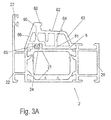
- FIG. 3A the sealing profile 6 is shown in a mounted on the frame profile 2 position.
- the frame profile 2 is constructed identical to the frame profile 3 and also the frame profiles 2 'and 3' can be designed accordingly.
- the frame profile 2 comprises an inner shell 20 made of aluminum and an outer shell 22 made of aluminum, which are connected to each other via insulating webs 21 made of plastic.
- inside and outside refer to the preferred installation situation of a window or a door with a frame profile 2, 3, 2 'or 3' and are also interchangeable with reverse installation.
- a groove 24 is formed, in which a foot portion 60 of the sealing profile 6 is inserted and is fixed on the inner directed webs of the groove 24.
- the sealing profile 6 is formed as a hollow chamber profile and has an outer wall 61 and an inner wall 62, wherein on the inner wall 62, a sealing projection 69 is integrally formed.
- the inner wall 62 is connected to the outer wall 61 via a plurality of intermediate walls.
- the terms “inside” and “outside” refer here to the corner region in which the sealing profile 6 is bent and therefore radially inner and outer regions are present.
- FIG. 3B is the frame profile 2 of FIG. 3A shown together with a wing profile 7 which is movable relative to the frame profile 2.
- the wing profile is formed as a thermally insulated composite profile and has on its outer side a bearing surface 71 which cooperates with a sealing profile which is fixed in the groove 23.
- the airfoil 7 has on the inside a groove 72 on which an inner gasket is drawn, which cooperates with the inner shell 20 of the frame profile 2, so that the sealing profile 6 is formed as a central seal, which is arranged between an outer and an inner seal.
- the sealing profile 6 extends substantially over the width of the insulating webs 21st
- the sealing profile 6 rests with the sealing projection 69 on a block 70, which is part of an insulating web of the airfoil 7.
- the block 70 deforms the sealing profile 6 as shown in FIG FIG. 3C is shown.
- the sealing projection 69 abuts with a sealing surface on the block 70, wherein the sealing profile 6 in the region of the inner wall 62 to the left in FIG. 3C was moved.
- the inner wall 62 is displaceable relative to the outer wall 61 via the intermediate walls 63, 64, 65 and 66 in the manner of a parallelogram, wherein in FIG. 3C the original position of the intermediate wall 63 is shown in dashed lines and the pivoted position with 63 '.
- the sealing profile 6 is shown in detail.
- the sealing profile 6 consists of an elastic material, in particular a foamed Cell or sponge rubber, which is spilled on the inside.
- the sealing profile 6 has an outer wall 61 and an inner wall 62, wherein the term “outside” and “inside” refer to a corner portion of a frame or a T-joint, on which the outer wall 61 is on the outside and the inner wall 62 is provided lying inside.
- the outer wall 61 and the inner wall 62 are connected to each other via four intermediate walls 63, 64, 65, and 66, wherein the number of intermediate walls 63, 64, 65, 66 can be varied to the number of hollow chambers in the sealing profile 6 vary.
- a partition wall 68 is further formed, which is free-hanging and does not extend to the outer wall 61.
- a foot part 60 is further shown with a mushroom-shaped cross section and adjacent to the foot part 60, a support web 67 is provided which supports the sealing profile 6 when the sealing projection 69 is pushed into a closed position, as in FIG. 3C is shown.
- FIG. 5A the sealing profile 6 is shown in a state during assembly.
- the sealing profile 6 is cut in a corner region, wherein at least the outer wall 61 is severed, but preferably also a part of the intermediate walls 63, 64, 65 and 66, which can for example also be completely severed. Only the inner wall 62 must remain at least partially continuous, so that the sealing profile 6 can be aligned at an angle after the incision, as in FIG. 5A is shown.
- the hollow chambers are opened and in the corner region of the sealing profile 6, a corner element 5 is arranged.
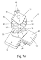
- the corner element 5 is essentially formed by a cuboid web which has angled protrusions 53, 54 and 55 which can be inserted into the individual hollow chambers of the sealing profile 6. Furthermore, the corner element 5 has two plates 52 protruding at right angles, which can be fixed to a frame profile 2, 3, 2 ', 3' and also provide for the distribution of a sealing compound. Via a channel 10, a sealing compound is injected into the corner element 5 after assembly.
- the corner element 5 adapts to the cut-in end edges of the sealing profile 6 substantially form-fitting and closes them.
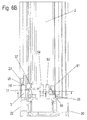
- An upper side 51 of the corner element 5 is aligned substantially flush with an outer side of the sealing profile 6 and the projections 53, 54 and 55 are inserted into the hollow chambers of the sealing profile 6, so that the sealing profile 6 is kept pre-fixed via the corner element 5 in the angled position.
- FIG. 6A the sealing profile 6 is shown in a position mounted on the corner element 5, wherein the corner element 5 is fixed to the frame profile 2.
- the plates 52 on the corner element 5 have groove-shaped channels 13 and 14, engage in the webs of the groove 23 on the outer shell 22 of the frame profile 2.
- FIG. 6B the corner element 5 can be fixed between the outer shell 22 and the inner shell 20, wherein for this purpose on the corner element 5 adjacent to the upper side 51, a latching element 46 engages in a groove 26 on the inner shell 20.
- a latching means 56 is also provided on the corner element 5, which engages in a groove 25 on the outer shell 22.
- the latching means 46 and 56 in the corner element 5 are at least partially elastic and allow latching of the corner element 5 during assembly. It is also possible to form the corner element 5 in total of a material with a certain elasticity or to provide at least individual sections of an elastic material.
- FIG. 6C is a section through the corner element 5 is shown, wherein the channel 10 is recognizable for distributing sealing compound.
- the channel 10 is connected via one or more distribution sections to the channels 13 and 14, so that at the top 51 injected sealant is distributed over the channel 10 in the corner.
- the channel 10 opens in the region of the miter surface 4 of two frame sections 2 and 3, wherein via the channels 13 and 14, a seal in the region of an abutment surface 4 'can be prepared by the sealant.
- openings 16 are provided on the side facing the sealing profile 6 on the channel 10 in order to inject sealing compound into the hollow chambers of the sealing profile 6 and to securely seal this region.
- a further opening 18 is provided on the channel 10 in order to inject sealant in this area can.
- the corner element 5 is preferably made of plastic and can be dimensionally stable in the corner region of two frame profiles 2 and 3 or 2 'and 3' fixed are, for easy installation, the corner element 5 via one or more locking means 46 and 56 can be latched.
- the corner element 5 comprises at the cuboid web a plurality of web-shaped projections 53, 54 and 55, which are insertable into the hollow chambers of the sealing profile 6.
- the projections 53, 54, 55 are aligned angularly, preferably substantially at a right angle, in order to prefix the sealing profile 6 in an angular position can.
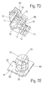
- the sealant is then distributed over the channel 10, wherein the channel 10 is arranged on the opposite side in the region of the plates 52 and there distributed over a first distribution section 12 sealing compound along the miter surface 4 of a frame 1.
- the first distribution section 12 is connected via two groove-shaped distribution sections 11, which transport the sealant to the groove-shaped channels 13 and 14.
- an opening 15 is formed, which is provided at the top of the plate 52 and allows an optical control, whether sufficient sealant was injected into the corner element 5, because at a sufficient filling of the corner element 5 sealing compound from the opening 15th out.
- locking elements 55 and 56 are further formed on opposite sides, which can be latched to a frame profile 2 at corresponding webs or grooves 26 and 25.
- a plate 57 is further provided, which tapers pointedly to the front and engages under an outer wall of the sealing profile.
- the plates 52 are arranged at a distance from the sealing profile 6.
- a recess 17 is provided, which is used as needed for injecting sealant by the bottom wall of the recess 17 is broken, so that then a nozzle can be inserted into the channel 10.
- the corner element 5 is formed in two parts and comprises a first part 58 made of a softer, elastic material and a second part 59 of a more dimensionally stable material.
- the first part 58 made of softer material allows latching of the corner element 5 on a frame profile 2, 3, 2 ', 3'.
- the first part 58 has for this purpose a sleeve 40 which can be inserted into the channel 10 on the second part 59, so that after assembly, the first part 58 and the second part 59 are firmly connected to each other.
- a sealing profile 6 is cut in the region of an outer wall 61 and preferably also in the region of the intermediate walls 63, 64, 65 and 66 and bent or folded over.
- a corner element 5 is then inserted, as shown in the Figures 5A and 5B is shown.
- the corner element 5 can either be pre-mounted on a frame 1 or a T-connection 1 'or be mounted loosely on the sealing profile 6, so that then the unit of sealing profile 6 and corner element 5 on a frame 1 or a T-connection 1' can be mounted.
- After mounting the sealing profile 6 on the frame 1 or the T-joint 1 'sealing compound is then injected into the channel 10 and distributed in the corner element 5 to the frame profiles 2, 3, 2', 3 'to seal accordingly.
- the sealing profile 6 When mounting a frame, the sealing profile 6 is held over four corner elements 5, wherein the sealing profile 6 is preferably provided in one piece.
- the sealing profile 6 is in the region of the end portions with the end faces to each other to obtain a sufficient seal.
Landscapes
- Engineering & Computer Science (AREA)
- Civil Engineering (AREA)
- Structural Engineering (AREA)
- Joining Of Corner Units Of Frames Or Wings (AREA)
Applications Claiming Priority (1)
| Application Number | Priority Date | Filing Date | Title |
|---|---|---|---|
| DE102013100241.2A DE102013100241A1 (de) | 2013-01-11 | 2013-01-11 | Rahmen oder T-Verbindung |
Publications (2)
| Publication Number | Publication Date |
|---|---|
| EP2754838A1 true EP2754838A1 (fr) | 2014-07-16 |
| EP2754838B1 EP2754838B1 (fr) | 2016-06-15 |
Family
ID=49765312
Family Applications (1)
| Application Number | Title | Priority Date | Filing Date |
|---|---|---|---|
| EP13195641.9A Active EP2754838B1 (fr) | 2013-01-11 | 2013-12-04 | Cadre ou liaison en T |
Country Status (2)
| Country | Link |
|---|---|
| EP (1) | EP2754838B1 (fr) |
| DE (1) | DE102013100241A1 (fr) |
Families Citing this family (1)
| Publication number | Priority date | Publication date | Assignee | Title |
|---|---|---|---|---|
| DE102022103403B4 (de) | 2022-02-14 | 2025-08-14 | HUECK System GmbH & Co. KG | Eckabdichtungselement |
Citations (8)
| Publication number | Priority date | Publication date | Assignee | Title |
|---|---|---|---|---|
| FR2283295A1 (fr) * | 1974-08-26 | 1976-03-26 | Frank Gmbh Wilh | Chassis profile creux, notamment pour battant de fenetre, porte ou analogue |
| GB1460169A (en) * | 1974-03-13 | 1976-12-31 | Schlegel Uk Ltd | Moulded corners or joints of door seals and the like |
| DE2460417C2 (de) * | 1974-01-09 | 1986-09-11 | Draftex S.A., Chartres, Eure-et-Loir | Verfahren zum Formen einer scharfen Ecke aus einer Länge eines Dichtungsstreifens |
| DE20213859U1 (de) * | 2002-09-07 | 2003-10-09 | Henkenjohann, Johann, 33415 Verl | Formecke für Mitteldichtungen |
| EP1712723A1 (fr) * | 2005-04-05 | 2006-10-18 | Norsk Hydro Asa | Porte, fenêtre, ou analogue, à châssis de type battant, comportant un joint d'étanchéïté centrale tournant |
| EP1811117A1 (fr) * | 2006-01-20 | 2007-07-25 | Norsk Hydro Asa | Joint réversible pour des cadres de portes ou de fenêtres à joint ouvert |
| EP1972749A1 (fr) | 2007-02-23 | 2008-09-24 | Norsk Hydro ASA | Porte, fenêtre, ou analogue, comportant des moyens de guidage latéral du bord libre du joint d'étanchéite centrale |
| DE202010008921U1 (de) * | 2010-10-28 | 2010-12-30 | SCHÜCO International KG | Mitteldichtung für hoch wärmegedämmte Fenster oder Türen |
Family Cites Families (1)
| Publication number | Priority date | Publication date | Assignee | Title |
|---|---|---|---|---|
| DE3809773A1 (de) * | 1988-03-23 | 1989-10-12 | Rolf Stark | Arbeitsverfahren zum bilden von eckverbindungen an abdichtungsprofilen und geraet zur durchfuehrung dieses verfahrens |
-
2013
- 2013-01-11 DE DE102013100241.2A patent/DE102013100241A1/de not_active Withdrawn
- 2013-12-04 EP EP13195641.9A patent/EP2754838B1/fr active Active
Patent Citations (8)
| Publication number | Priority date | Publication date | Assignee | Title |
|---|---|---|---|---|
| DE2460417C2 (de) * | 1974-01-09 | 1986-09-11 | Draftex S.A., Chartres, Eure-et-Loir | Verfahren zum Formen einer scharfen Ecke aus einer Länge eines Dichtungsstreifens |
| GB1460169A (en) * | 1974-03-13 | 1976-12-31 | Schlegel Uk Ltd | Moulded corners or joints of door seals and the like |
| FR2283295A1 (fr) * | 1974-08-26 | 1976-03-26 | Frank Gmbh Wilh | Chassis profile creux, notamment pour battant de fenetre, porte ou analogue |
| DE20213859U1 (de) * | 2002-09-07 | 2003-10-09 | Henkenjohann, Johann, 33415 Verl | Formecke für Mitteldichtungen |
| EP1712723A1 (fr) * | 2005-04-05 | 2006-10-18 | Norsk Hydro Asa | Porte, fenêtre, ou analogue, à châssis de type battant, comportant un joint d'étanchéïté centrale tournant |
| EP1811117A1 (fr) * | 2006-01-20 | 2007-07-25 | Norsk Hydro Asa | Joint réversible pour des cadres de portes ou de fenêtres à joint ouvert |
| EP1972749A1 (fr) | 2007-02-23 | 2008-09-24 | Norsk Hydro ASA | Porte, fenêtre, ou analogue, comportant des moyens de guidage latéral du bord libre du joint d'étanchéite centrale |
| DE202010008921U1 (de) * | 2010-10-28 | 2010-12-30 | SCHÜCO International KG | Mitteldichtung für hoch wärmegedämmte Fenster oder Türen |
Also Published As
| Publication number | Publication date |
|---|---|
| DE102013100241A1 (de) | 2014-07-17 |
| EP2754838B1 (fr) | 2016-06-15 |
Similar Documents
| Publication | Publication Date | Title |
|---|---|---|
| EP0616107B1 (fr) | Raccord à onglet d'éléments profilés | |
| WO2005068764A1 (fr) | Cadre pour une porte coulissante ou pour une fenetre coulissante | |
| EP0569986B1 (fr) | Pièce d'assemblage pour profilés creux se raccordant sous un angle | |
| EP2754842B1 (fr) | Profil d'étanchéité pour un profil de cadre et profil de cadre | |
| DE102020126640A1 (de) | System mit einem Schwellenprofil, einem Blendrahmenprofil und einem Schwellenverbinder eines Fensters oder einer Tür | |
| DE102011120374A1 (de) | Eckverbinderprofil mit schlitzförmiger Nut | |
| EP0651125A1 (fr) | Pièce d'assemblage pour profilés se raccordant sous un angle | |
| EP2754839B1 (fr) | Cadre ou liaison en T et procédé de montage d'un cadre ou d'une liaison en T | |
| DE102011002677A1 (de) | Motagehilfseinrichtung für einen Flügel einer Tür, eines Fensters oder dergleichen | |
| EP2754838B1 (fr) | Cadre ou liaison en T | |
| EP2995929B1 (fr) | Chambre de test climatisée | |
| EP1956174B1 (fr) | Rail de profilé destiné au positionnement d'un élément de fixation et procédé de fabrication d'une unité de vitrification multiple | |
| DE102015200616A1 (de) | Dachfenster sowie Verfahren zum Montieren eines Dachfensters | |
| WO2014114785A1 (fr) | Joint en équerre et raccord d'angle pour ce dernier | |
| EP2444566A2 (fr) | Agencement de deux profilés disposés à un angle l'un par rapport à l'autre ainsi qu'un élément d'étanchéité | |
| DE29617862U1 (de) | Wand- und/oder Türelement sowie Rahmenteil und Deckplatte zu dessen Herstellung | |
| DE102020132402B4 (de) | Eckschweißverbinder mit Kappe für Kunststoffhohlprofile, dessen Kombination mit einem Kunststoffhohlprofil und Verfahren zur Herstellung einer Eckschweißverbindung | |
| EP3992409B1 (fr) | Élément de fenêtre doté d'une vitre de fenêtre collée dans un cadre | |
| DE2810981C2 (de) | Vorrichtung zur Befestigung einer Zarge | |
| DE102012102176A1 (de) | Stoßverbindung und Rahmenkonstruktion | |
| DE10006962A1 (de) | Eckwinkel mit Endabdichtung | |
| DE102009051319A1 (de) | Glasverbundscheibe | |
| WO2006027082A1 (fr) | Ensemble d'elements comprenant au moins un meneau et au moins deux pieces d'extremite de meneau a integrer dans une vitre isolante | |
| EP3299567A1 (fr) | Structure de poutre pour une fermeture de bâtiment, procédé de fabrication d'une structure de poutre ainsi que fermeture de bâtiment | |
| EP4191012A1 (fr) | Élément de fermeture d'ouverture de bâtiment et son procédé de fabrication |
Legal Events
| Date | Code | Title | Description |
|---|---|---|---|
| PUAI | Public reference made under article 153(3) epc to a published international application that has entered the european phase |
Free format text: ORIGINAL CODE: 0009012 |
|
| 17P | Request for examination filed |
Effective date: 20131204 |
|
| AK | Designated contracting states |
Kind code of ref document: A1 Designated state(s): AL AT BE BG CH CY CZ DE DK EE ES FI FR GB GR HR HU IE IS IT LI LT LU LV MC MK MT NL NO PL PT RO RS SE SI SK SM TR |
|
| AX | Request for extension of the european patent |
Extension state: BA ME |
|
| R17P | Request for examination filed (corrected) |
Effective date: 20150112 |
|
| RBV | Designated contracting states (corrected) |
Designated state(s): AL AT BE BG CH CY CZ DE DK EE ES FI FR GB GR HR HU IE IS IT LI LT LU LV MC MK MT NL NO PL PT RO RS SE SI SK SM TR |
|
| GRAP | Despatch of communication of intention to grant a patent |
Free format text: ORIGINAL CODE: EPIDOSNIGR1 |
|
| RIC1 | Information provided on ipc code assigned before grant |
Ipc: E06B 3/263 20060101ALI20160127BHEP Ipc: E06B 3/62 20060101ALI20160127BHEP Ipc: E06B 7/23 20060101ALI20160127BHEP Ipc: E06B 3/976 20060101ALI20160127BHEP Ipc: E06B 3/96 20060101AFI20160127BHEP |
|
| INTG | Intention to grant announced |
Effective date: 20160212 |
|
| GRAS | Grant fee paid |
Free format text: ORIGINAL CODE: EPIDOSNIGR3 |
|
| GRAA | (expected) grant |
Free format text: ORIGINAL CODE: 0009210 |
|
| AK | Designated contracting states |
Kind code of ref document: B1 Designated state(s): AL AT BE BG CH CY CZ DE DK EE ES FI FR GB GR HR HU IE IS IT LI LT LU LV MC MK MT NL NO PL PT RO RS SE SI SK SM TR |
|
| REG | Reference to a national code |
Ref country code: CH Ref legal event code: EP Ref country code: GB Ref legal event code: FG4D Free format text: NOT ENGLISH |
|
| REG | Reference to a national code |
Ref country code: IE Ref legal event code: FG4D Free format text: LANGUAGE OF EP DOCUMENT: GERMAN |
|
| REG | Reference to a national code |
Ref country code: AT Ref legal event code: REF Ref document number: 806613 Country of ref document: AT Kind code of ref document: T Effective date: 20160715 |
|
| REG | Reference to a national code |
Ref country code: DE Ref legal event code: R096 Ref document number: 502013003394 Country of ref document: DE |
|
| REG | Reference to a national code |
Ref country code: CH Ref legal event code: NV Representative=s name: ISLER AND PEDRAZZINI AG, CH |
|
| REG | Reference to a national code |
Ref country code: LT Ref legal event code: MG4D |
|
| REG | Reference to a national code |
Ref country code: EE Ref legal event code: FG4A Ref document number: E012382 Country of ref document: EE Effective date: 20160801 |
|
| REG | Reference to a national code |
Ref country code: NL Ref legal event code: MP Effective date: 20160615 |
|
| PG25 | Lapsed in a contracting state [announced via postgrant information from national office to epo] |
Ref country code: NO Free format text: LAPSE BECAUSE OF FAILURE TO SUBMIT A TRANSLATION OF THE DESCRIPTION OR TO PAY THE FEE WITHIN THE PRESCRIBED TIME-LIMIT Effective date: 20160915 Ref country code: FI Free format text: LAPSE BECAUSE OF FAILURE TO SUBMIT A TRANSLATION OF THE DESCRIPTION OR TO PAY THE FEE WITHIN THE PRESCRIBED TIME-LIMIT Effective date: 20160615 Ref country code: LT Free format text: LAPSE BECAUSE OF FAILURE TO SUBMIT A TRANSLATION OF THE DESCRIPTION OR TO PAY THE FEE WITHIN THE PRESCRIBED TIME-LIMIT Effective date: 20160615 |
|
| PG25 | Lapsed in a contracting state [announced via postgrant information from national office to epo] |
Ref country code: RS Free format text: LAPSE BECAUSE OF FAILURE TO SUBMIT A TRANSLATION OF THE DESCRIPTION OR TO PAY THE FEE WITHIN THE PRESCRIBED TIME-LIMIT Effective date: 20160615 Ref country code: SE Free format text: LAPSE BECAUSE OF FAILURE TO SUBMIT A TRANSLATION OF THE DESCRIPTION OR TO PAY THE FEE WITHIN THE PRESCRIBED TIME-LIMIT Effective date: 20160615 Ref country code: HR Free format text: LAPSE BECAUSE OF FAILURE TO SUBMIT A TRANSLATION OF THE DESCRIPTION OR TO PAY THE FEE WITHIN THE PRESCRIBED TIME-LIMIT Effective date: 20160615 Ref country code: NL Free format text: LAPSE BECAUSE OF FAILURE TO SUBMIT A TRANSLATION OF THE DESCRIPTION OR TO PAY THE FEE WITHIN THE PRESCRIBED TIME-LIMIT Effective date: 20160615 Ref country code: GR Free format text: LAPSE BECAUSE OF FAILURE TO SUBMIT A TRANSLATION OF THE DESCRIPTION OR TO PAY THE FEE WITHIN THE PRESCRIBED TIME-LIMIT Effective date: 20160916 |
|
| REG | Reference to a national code |
Ref country code: FR Ref legal event code: PLFP Year of fee payment: 4 |
|
| PG25 | Lapsed in a contracting state [announced via postgrant information from national office to epo] |
Ref country code: RO Free format text: LAPSE BECAUSE OF FAILURE TO SUBMIT A TRANSLATION OF THE DESCRIPTION OR TO PAY THE FEE WITHIN THE PRESCRIBED TIME-LIMIT Effective date: 20160615 Ref country code: SK Free format text: LAPSE BECAUSE OF FAILURE TO SUBMIT A TRANSLATION OF THE DESCRIPTION OR TO PAY THE FEE WITHIN THE PRESCRIBED TIME-LIMIT Effective date: 20160615 Ref country code: CZ Free format text: LAPSE BECAUSE OF FAILURE TO SUBMIT A TRANSLATION OF THE DESCRIPTION OR TO PAY THE FEE WITHIN THE PRESCRIBED TIME-LIMIT Effective date: 20160615 Ref country code: IS Free format text: LAPSE BECAUSE OF FAILURE TO SUBMIT A TRANSLATION OF THE DESCRIPTION OR TO PAY THE FEE WITHIN THE PRESCRIBED TIME-LIMIT Effective date: 20161015 |
|
| PG25 | Lapsed in a contracting state [announced via postgrant information from national office to epo] |
Ref country code: PT Free format text: LAPSE BECAUSE OF FAILURE TO SUBMIT A TRANSLATION OF THE DESCRIPTION OR TO PAY THE FEE WITHIN THE PRESCRIBED TIME-LIMIT Effective date: 20161017 Ref country code: SM Free format text: LAPSE BECAUSE OF FAILURE TO SUBMIT A TRANSLATION OF THE DESCRIPTION OR TO PAY THE FEE WITHIN THE PRESCRIBED TIME-LIMIT Effective date: 20160615 Ref country code: ES Free format text: LAPSE BECAUSE OF FAILURE TO SUBMIT A TRANSLATION OF THE DESCRIPTION OR TO PAY THE FEE WITHIN THE PRESCRIBED TIME-LIMIT Effective date: 20160615 Ref country code: PL Free format text: LAPSE BECAUSE OF FAILURE TO SUBMIT A TRANSLATION OF THE DESCRIPTION OR TO PAY THE FEE WITHIN THE PRESCRIBED TIME-LIMIT Effective date: 20160615 |
|
| REG | Reference to a national code |
Ref country code: DE Ref legal event code: R097 Ref document number: 502013003394 Country of ref document: DE |
|
| PLBE | No opposition filed within time limit |
Free format text: ORIGINAL CODE: 0009261 |
|
| STAA | Information on the status of an ep patent application or granted ep patent |
Free format text: STATUS: NO OPPOSITION FILED WITHIN TIME LIMIT |
|
| 26N | No opposition filed |
Effective date: 20170316 |
|
| PG25 | Lapsed in a contracting state [announced via postgrant information from national office to epo] |
Ref country code: DK Free format text: LAPSE BECAUSE OF FAILURE TO SUBMIT A TRANSLATION OF THE DESCRIPTION OR TO PAY THE FEE WITHIN THE PRESCRIBED TIME-LIMIT Effective date: 20160615 Ref country code: BE Free format text: LAPSE BECAUSE OF NON-PAYMENT OF DUE FEES Effective date: 20161231 |
|
| PG25 | Lapsed in a contracting state [announced via postgrant information from national office to epo] |
Ref country code: SI Free format text: LAPSE BECAUSE OF FAILURE TO SUBMIT A TRANSLATION OF THE DESCRIPTION OR TO PAY THE FEE WITHIN THE PRESCRIBED TIME-LIMIT Effective date: 20160615 |
|
| PG25 | Lapsed in a contracting state [announced via postgrant information from national office to epo] |
Ref country code: MC Free format text: LAPSE BECAUSE OF FAILURE TO SUBMIT A TRANSLATION OF THE DESCRIPTION OR TO PAY THE FEE WITHIN THE PRESCRIBED TIME-LIMIT Effective date: 20160615 |
|
| REG | Reference to a national code |
Ref country code: IE Ref legal event code: MM4A |
|
| PG25 | Lapsed in a contracting state [announced via postgrant information from national office to epo] |
Ref country code: LU Free format text: LAPSE BECAUSE OF NON-PAYMENT OF DUE FEES Effective date: 20161204 |
|
| PG25 | Lapsed in a contracting state [announced via postgrant information from national office to epo] |
Ref country code: IE Free format text: LAPSE BECAUSE OF NON-PAYMENT OF DUE FEES Effective date: 20161204 |
|
| REG | Reference to a national code |
Ref country code: FR Ref legal event code: PLFP Year of fee payment: 5 |
|
| REG | Reference to a national code |
Ref country code: BE Ref legal event code: MM Effective date: 20161231 |
|
| PG25 | Lapsed in a contracting state [announced via postgrant information from national office to epo] |
Ref country code: HU Free format text: LAPSE BECAUSE OF FAILURE TO SUBMIT A TRANSLATION OF THE DESCRIPTION OR TO PAY THE FEE WITHIN THE PRESCRIBED TIME-LIMIT; INVALID AB INITIO Effective date: 20131204 |
|
| PG25 | Lapsed in a contracting state [announced via postgrant information from national office to epo] |
Ref country code: MK Free format text: LAPSE BECAUSE OF FAILURE TO SUBMIT A TRANSLATION OF THE DESCRIPTION OR TO PAY THE FEE WITHIN THE PRESCRIBED TIME-LIMIT Effective date: 20160615 Ref country code: CY Free format text: LAPSE BECAUSE OF FAILURE TO SUBMIT A TRANSLATION OF THE DESCRIPTION OR TO PAY THE FEE WITHIN THE PRESCRIBED TIME-LIMIT Effective date: 20160615 |
|
| PG25 | Lapsed in a contracting state [announced via postgrant information from national office to epo] |
Ref country code: BG Free format text: LAPSE BECAUSE OF FAILURE TO SUBMIT A TRANSLATION OF THE DESCRIPTION OR TO PAY THE FEE WITHIN THE PRESCRIBED TIME-LIMIT Effective date: 20160615 |
|
| PG25 | Lapsed in a contracting state [announced via postgrant information from national office to epo] |
Ref country code: MT Free format text: LAPSE BECAUSE OF FAILURE TO SUBMIT A TRANSLATION OF THE DESCRIPTION OR TO PAY THE FEE WITHIN THE PRESCRIBED TIME-LIMIT Effective date: 20160615 |
|
| PG25 | Lapsed in a contracting state [announced via postgrant information from national office to epo] |
Ref country code: TR Free format text: LAPSE BECAUSE OF FAILURE TO SUBMIT A TRANSLATION OF THE DESCRIPTION OR TO PAY THE FEE WITHIN THE PRESCRIBED TIME-LIMIT Effective date: 20160615 Ref country code: AL Free format text: LAPSE BECAUSE OF FAILURE TO SUBMIT A TRANSLATION OF THE DESCRIPTION OR TO PAY THE FEE WITHIN THE PRESCRIBED TIME-LIMIT Effective date: 20160615 |
|
| REG | Reference to a national code |
Ref country code: EE Ref legal event code: HC1A Ref document number: E012382 Country of ref document: EE |
|
| P01 | Opt-out of the competence of the unified patent court (upc) registered |
Effective date: 20230814 |
|
| PGFP | Annual fee paid to national office [announced via postgrant information from national office to epo] |
Ref country code: LV Payment date: 20231214 Year of fee payment: 11 Ref country code: EE Payment date: 20231222 Year of fee payment: 11 Ref country code: AT Payment date: 20231204 Year of fee payment: 11 |
|
| PGFP | Annual fee paid to national office [announced via postgrant information from national office to epo] |
Ref country code: CH Payment date: 20240102 Year of fee payment: 11 |
|
| PG25 | Lapsed in a contracting state [announced via postgrant information from national office to epo] |
Ref country code: LV Free format text: LAPSE BECAUSE OF NON-PAYMENT OF DUE FEES Effective date: 20241204 |
|
| REG | Reference to a national code |
Ref country code: CH Ref legal event code: PL |
|
| REG | Reference to a national code |
Ref country code: AT Ref legal event code: MM01 Ref document number: 806613 Country of ref document: AT Kind code of ref document: T Effective date: 20241204 |
|
| PG25 | Lapsed in a contracting state [announced via postgrant information from national office to epo] |
Ref country code: AT Free format text: LAPSE BECAUSE OF NON-PAYMENT OF DUE FEES Effective date: 20241204 |
|
| PG25 | Lapsed in a contracting state [announced via postgrant information from national office to epo] |
Ref country code: CH Free format text: LAPSE BECAUSE OF NON-PAYMENT OF DUE FEES Effective date: 20241231 |
|
| PG25 | Lapsed in a contracting state [announced via postgrant information from national office to epo] |
Ref country code: EE Free format text: LAPSE BECAUSE OF NON-PAYMENT OF DUE FEES Effective date: 20241231 |
|
| PGFP | Annual fee paid to national office [announced via postgrant information from national office to epo] |
Ref country code: DE Payment date: 20251020 Year of fee payment: 13 |
|
| PGFP | Annual fee paid to national office [announced via postgrant information from national office to epo] |
Ref country code: GB Payment date: 20251203 Year of fee payment: 13 |
|
| PGFP | Annual fee paid to national office [announced via postgrant information from national office to epo] |
Ref country code: FR Payment date: 20251203 Year of fee payment: 13 |
|
| PGFP | Annual fee paid to national office [announced via postgrant information from national office to epo] |
Ref country code: IT Payment date: 20251231 Year of fee payment: 13 |