EP2754840A2 - Raccord d'angle - Google Patents
Raccord d'angle Download PDFInfo
- Publication number
- EP2754840A2 EP2754840A2 EP13197433.9A EP13197433A EP2754840A2 EP 2754840 A2 EP2754840 A2 EP 2754840A2 EP 13197433 A EP13197433 A EP 13197433A EP 2754840 A2 EP2754840 A2 EP 2754840A2
- Authority
- EP
- European Patent Office
- Prior art keywords
- corner connector
- distribution channel
- corner
- recesses
- connector
- Prior art date
- Legal status (The legal status is an assumption and is not a legal conclusion. Google has not performed a legal analysis and makes no representation as to the accuracy of the status listed.)
- Granted
Links
Images

Classifications
-
- E—FIXED CONSTRUCTIONS
- E06—DOORS, WINDOWS, SHUTTERS, OR ROLLER BLINDS IN GENERAL; LADDERS
- E06B—FIXED OR MOVABLE CLOSURES FOR OPENINGS IN BUILDINGS, VEHICLES, FENCES OR LIKE ENCLOSURES IN GENERAL, e.g. DOORS, WINDOWS, BLINDS, GATES
- E06B3/00—Window sashes, door leaves, or like elements for closing wall or like openings; Layout of fixed or moving closures, e.g. windows in wall or like openings; Features of rigidly-mounted outer frames relating to the mounting of wing frames
- E06B3/96—Corner joints or edge joints for windows, doors, or the like frames or wings
- E06B3/9612—Corner joints or edge joints for windows, doors, or the like frames or wings by filling in situ the hollow ends of the abutted frame members with a hardenable substance
-
- E—FIXED CONSTRUCTIONS
- E06—DOORS, WINDOWS, SHUTTERS, OR ROLLER BLINDS IN GENERAL; LADDERS
- E06B—FIXED OR MOVABLE CLOSURES FOR OPENINGS IN BUILDINGS, VEHICLES, FENCES OR LIKE ENCLOSURES IN GENERAL, e.g. DOORS, WINDOWS, BLINDS, GATES
- E06B3/00—Window sashes, door leaves, or like elements for closing wall or like openings; Layout of fixed or moving closures, e.g. windows in wall or like openings; Features of rigidly-mounted outer frames relating to the mounting of wing frames
- E06B3/96—Corner joints or edge joints for windows, doors, or the like frames or wings
- E06B3/964—Corner joints or edge joints for windows, doors, or the like frames or wings using separate connection pieces, e.g. T-connection pieces
- E06B3/9645—Mitre joints
-
- E—FIXED CONSTRUCTIONS
- E06—DOORS, WINDOWS, SHUTTERS, OR ROLLER BLINDS IN GENERAL; LADDERS
- E06B—FIXED OR MOVABLE CLOSURES FOR OPENINGS IN BUILDINGS, VEHICLES, FENCES OR LIKE ENCLOSURES IN GENERAL, e.g. DOORS, WINDOWS, BLINDS, GATES
- E06B3/00—Window sashes, door leaves, or like elements for closing wall or like openings; Layout of fixed or moving closures, e.g. windows in wall or like openings; Features of rigidly-mounted outer frames relating to the mounting of wing frames
- E06B3/96—Corner joints or edge joints for windows, doors, or the like frames or wings
- E06B3/964—Corner joints or edge joints for windows, doors, or the like frames or wings using separate connection pieces, e.g. T-connection pieces
- E06B3/968—Corner joints or edge joints for windows, doors, or the like frames or wings using separate connection pieces, e.g. T-connection pieces characterised by the way the connecting pieces are fixed in or on the frame members
- E06B3/9681—Corner joints or edge joints for windows, doors, or the like frames or wings using separate connection pieces, e.g. T-connection pieces characterised by the way the connecting pieces are fixed in or on the frame members by press fit or adhesion
- E06B3/9682—Mitre joints
Definitions
- the present invention relates to a one-part or multi-part corner connector for connecting two miter-cut hollow profiles according to the preamble of claim 1, a method for producing such a corner connector according to claim 8 and an arrangement comprising such a corner connector according to claim 10.
- Such a corner connector is from the EP 2 154 323 A2 known. It can be used to form a compound of two mitred hollow sections. The corner connector is inserted into the hollow sections. An adhesive is placed between the corner connector and the hollow sections so that a reliable connection takes place.
- two recesses referred to as passages are interconnected by both a supply channel and a distribution channel.
- the adhesive can be introduced, which then passes through the supply channel and the distribution channel in the other recess.
- a particularly good adhesive bond can be achieved.
- the distribution channel extends on a surface of the corner connector that is perpendicular to the surface of the corner connector where the supply channel is extending.
- a Insert the router first into the feed channel and then into the distribution channel in the corner connector or vice versa.
- the present invention seeks to provide a corner connector that is easier to produce, a simplified manufacturing method for a corner connector and an arrangement with such a corner connector.
- the recesses are interconnected only by exactly one distribution channel.
- the manufacture of the corner connector is simplified. After the corner connector without the distribution channel - for example in the extrusion process - was made, only the distribution channel must be introduced. This can be done for example by a milling.
- the corner connector can also be produced from two drawn profiles, which are connected to one another in the corner region. The connection of the two profiles can be done for example by mechanical pressing or pinning. Subsequently, the profiles can be additionally glued together by a sealant.
- the sealant is suitable for forming a material connection with the corner connector and with the hollow profiles, so that it could also be referred to as an adhesive.
- the sealant can now after the introduction of the corner connector in the hollow sections to be joined in one of the recesses be introduced. Since the two recesses are connected to each other via the distribution channel, the sealant also passes into the other of the recesses. Thus, a reliable connection of the corner connector is achieved with the hollow sections. A second processing step of the corner connector is not necessary.
- the distribution channel can be arranged in a corner region of the corner connector.
- the corner area lies with the connection of the hollow profiles in the area of the miter joint.
- the corner can run parallel to the miter.
- the corner area may in particular be wider than the miter joint itself.
- the corner region may have a width of about 0.3 cm to about 5 cm.
- the distribution channel can be arranged.
- the distribution channel can occupy the entire width of the corner or be narrower.
- the distribution channel can run parallel to the miter joint when the hollow profiles are connected to one another using the corner region.
- the distribution channel can in particular run parallel to the bisector of the angle formed by the corner connector.
- the distribution channel can run along the miter joint in the connection of the hollow profiles.
- the distribution channel can be configured in particular groove-shaped. Due to the course along the miter joint a particularly firm connection of the two hollow sections is achieved with each other, since they are connected by the sealant, which also enters the distribution channel, both together and with the corner profile.
- the distribution channel may extend from an outer side of the corner connector to an inner side of the corner connector.
- Under the side of the corner connector is understood in particular a side wall.
- the distribution channel can extend on a surface of the corner connector and thereby extend from one end of the surface to another end of the surface.
- the distribution channel may extend from an outside of the corner connector to an inside of the corner connector, in particular along the miter joint in the connection of the hollow profiles.
- the distribution channel can connect the two recesses with each other.
- the largest extent of the distribution channel may have in the direction of the miter. Nevertheless, the distribution channel can connect only the two recesses with each other. This ensures that the sealant passes from a recess through the distribution channel in the other recess.
- the distribution channel can only connect exactly the two recesses with each other.
- the distribution channel can also extend from the outside of the corner connector to the inside of the corner connector.
- the two recesses may be arranged on an outer side of the corner connector. This makes it particularly easy to fill the recesses with a sealant. Another advantage is that the sealant located in the recesses can form a cohesive connection with the hollow profiles to be joined.
- the corner connector may be formed in one piece or in one piece.
- the corner connector may be designed to be arranged within the hollow profiles.
- the invention relates to a method for producing a corner connector according to claim 8.
- a first method step the corner connector is produced without the distribution channel. This can be done, for example, as already described above, in the extrusion process or by connecting two profiles.
- the distribution channel can be introduced into the corner connector in a second method step, for example by milling or sawing.
- the invention relates to an assembly according to claim 10.
- the assembly comprises two hollow profiles which are interconnected using a corner joint according to an embodiment of the invention.
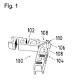
- FIG. 1 shows a corner connector 100.
- the corner connector 100 includes a first portion 102 and a second portion 104.
- the corner connector 100 can be made by extrusion or from two profiles. When made from two profiles, each profile can correspond to one of the sections 102 and 104. The two sections 102 and 104 adjoin one another in a corner region 106. If there are two profiles, the two profiles in the corner can be connected to each other - for example, via pins.
- a respective recess 108 is arranged, which are connected to one another via a distribution channel 110 arranged in the corner region 106.
- the distribution channel 110 can be milled into the corner connector 100, for example.
- the two recesses 108 are arranged on the outside of the corner connector 100, so that from the outside easily a sealant can be introduced into it.
- a sealant can be introduced into one of the recesses 108. From there the sealant in the distribution channel 110 and in the other recess 108. Thus, a stable connection of the hollow profiles using the corner connector 100 is achieved.
- the distribution channel 110 extends along the miter joint from an outer side of the corner connector 100 to an inner side. This ensures a particularly good and stable connection of the two hollow profiles with one another and with the corner connector 100, since the sealant can be distributed along the entire miter joint.
- arrow-shaped In the corner region 106 of the corner connector 100 is formed arrow-shaped. This arrow shape is particularly advantageous for a stable connection.
- the sealant can reach behind the arrowhead in the recesses 108, so that the connection is particularly stable.
- FIG. 2 shows the corner connector FIG. 1 as it was introduced into two hollow sections 200.
- the hollow profiles 200 are mitred so that a miter joint 202 is arranged between them.
- the in FIG. 2 Not visible - because with sealant covered - distribution channel 110 of the corner connector 100 extends along a portion of the miter joint 202.
- a sealant 206 is introduced into one of the recesses 108 using a tool 204, so that the sealant 206 passes both into the distribution channel 110 and into the other recess 108. In FIG. 2 this has already happened. Therefore, both both recesses 108 and the distribution channel 110 are filled with the sealant 206.
- the distribution channel 110 extends along part of the miter joint 202, a particularly stable connection of the hollow profiles 200 is achieved.
- a further advantage is that the sealant 206 only has to be introduced into one of the two recesses 108 and from there into the distribution channel 110 as well as into the respective other recess 108.
- the sealant 206 can be particularly easily introduced.
Landscapes
- Engineering & Computer Science (AREA)
- Civil Engineering (AREA)
- Structural Engineering (AREA)
- Mutual Connection Of Rods And Tubes (AREA)
- Connector Housings Or Holding Contact Members (AREA)
- Finishing Walls (AREA)
Applications Claiming Priority (1)
| Application Number | Priority Date | Filing Date | Title |
|---|---|---|---|
| DE102013100253.6A DE102013100253A1 (de) | 2013-01-11 | 2013-01-11 | Eckverbinder |
Publications (3)
| Publication Number | Publication Date |
|---|---|
| EP2754840A2 true EP2754840A2 (fr) | 2014-07-16 |
| EP2754840A3 EP2754840A3 (fr) | 2016-03-23 |
| EP2754840B1 EP2754840B1 (fr) | 2020-04-01 |
Family
ID=49884944
Family Applications (1)
| Application Number | Title | Priority Date | Filing Date |
|---|---|---|---|
| EP13197433.9A Active EP2754840B1 (fr) | 2013-01-11 | 2013-12-16 | Raccord d'angle |
Country Status (2)
| Country | Link |
|---|---|
| EP (1) | EP2754840B1 (fr) |
| DE (1) | DE102013100253A1 (fr) |
Cited By (7)
| Publication number | Priority date | Publication date | Assignee | Title |
|---|---|---|---|---|
| CN104847232A (zh) * | 2015-04-28 | 2015-08-19 | 广西德骏门窗幕墙有限公司 | 一种用于铝合金平开门窗的中梃连接件 |
| CN107191112A (zh) * | 2017-04-13 | 2017-09-22 | 广东坚朗五金制品股份有限公司 | 角部连接结构 |
| DE102017104463B3 (de) | 2017-03-03 | 2018-08-23 | Nieke Composites Gmbh | Leichtbaukonstruktion und Verfahren |
| JP2018204276A (ja) * | 2017-06-02 | 2018-12-27 | 日軽パネルシステム株式会社 | 開口枠の気密構造 |
| ES2759331A1 (es) * | 2018-11-07 | 2020-05-08 | Cano Manuel Blazquez | Escuadra de tetones |
| WO2024079075A1 (fr) * | 2022-10-12 | 2024-04-18 | REHAU Industries SE & Co. KG | Procédé de fabrication d'un joint d'angle, élément de liaison pour un joint d'angle et joint d'angle |
| US20250172036A1 (en) * | 2023-11-28 | 2025-05-29 | Mi Windows And Doors, Llc | Frame corner key |
Families Citing this family (1)
| Publication number | Priority date | Publication date | Assignee | Title |
|---|---|---|---|---|
| EP3835539B3 (fr) | 2019-12-13 | 2026-04-22 | Bash-tec GmbH | Kit pour un cadre |
Citations (1)
| Publication number | Priority date | Publication date | Assignee | Title |
|---|---|---|---|---|
| EP2154323A2 (fr) | 2008-08-08 | 2010-02-17 | Raico Bautechnik GmbH | Joint d'angle pour un assemblage à onglet de profiles creux |
Family Cites Families (8)
| Publication number | Priority date | Publication date | Assignee | Title |
|---|---|---|---|---|
| DE4303877A1 (de) * | 1993-02-10 | 1994-08-11 | Schueco Int Kg | Eckverbindung auf Gehrung geschnittener Hohlprofile eines Rahmens für Fenster, Türen oder Fassaden |
| FR2759111B1 (fr) * | 1997-02-06 | 1999-10-22 | Alcan France | Dispositif pour l'assemblage de profiles d'un chassis de porte, fenetre ou analogue |
| DE10118791B4 (de) * | 2001-04-18 | 2012-06-21 | Adrian Kosak | Verbindungselement |
| DE20114224U1 (de) * | 2001-08-29 | 2002-01-17 | Schüco International KG, 33609 Bielefeld | Vorrichtung zur Verbindung von Hohlprofilen zu Rahmenteilen |
| DE20217301U1 (de) * | 2002-11-09 | 2004-03-18 | SCHÜCO International KG | Eckverbinder für auf Gehrung geschnittene Hohlprofile eines Rahmens |
| DE102004014595B3 (de) * | 2004-03-23 | 2005-12-22 | Thyssen Schulte Gutmann Bausysteme Gmbh | Eckverbinder |
| DE102006047542B4 (de) * | 2006-10-07 | 2008-07-24 | Hydro Building Systems Gmbh | Rahmen für Fenster, Türen, Fassadenelemente und dergleichen |
| DE102011120374A1 (de) * | 2011-12-07 | 2013-06-13 | Heroal - Johann Henkenjohann Gmbh & Co. Kg | Eckverbinderprofil mit schlitzförmiger Nut |
-
2013
- 2013-01-11 DE DE102013100253.6A patent/DE102013100253A1/de not_active Withdrawn
- 2013-12-16 EP EP13197433.9A patent/EP2754840B1/fr active Active
Patent Citations (1)
| Publication number | Priority date | Publication date | Assignee | Title |
|---|---|---|---|---|
| EP2154323A2 (fr) | 2008-08-08 | 2010-02-17 | Raico Bautechnik GmbH | Joint d'angle pour un assemblage à onglet de profiles creux |
Cited By (9)
| Publication number | Priority date | Publication date | Assignee | Title |
|---|---|---|---|---|
| CN104847232A (zh) * | 2015-04-28 | 2015-08-19 | 广西德骏门窗幕墙有限公司 | 一种用于铝合金平开门窗的中梃连接件 |
| DE102017104463B3 (de) | 2017-03-03 | 2018-08-23 | Nieke Composites Gmbh | Leichtbaukonstruktion und Verfahren |
| CN107191112A (zh) * | 2017-04-13 | 2017-09-22 | 广东坚朗五金制品股份有限公司 | 角部连接结构 |
| CN107191112B (zh) * | 2017-04-13 | 2019-05-17 | 广东坚朗五金制品股份有限公司 | 角部连接结构 |
| JP2018204276A (ja) * | 2017-06-02 | 2018-12-27 | 日軽パネルシステム株式会社 | 開口枠の気密構造 |
| ES2759331A1 (es) * | 2018-11-07 | 2020-05-08 | Cano Manuel Blazquez | Escuadra de tetones |
| WO2020094894A1 (fr) * | 2018-11-07 | 2020-05-14 | Blazquez Cano Manuel | Équerre à tétons |
| WO2024079075A1 (fr) * | 2022-10-12 | 2024-04-18 | REHAU Industries SE & Co. KG | Procédé de fabrication d'un joint d'angle, élément de liaison pour un joint d'angle et joint d'angle |
| US20250172036A1 (en) * | 2023-11-28 | 2025-05-29 | Mi Windows And Doors, Llc | Frame corner key |
Also Published As
| Publication number | Publication date |
|---|---|
| DE102013100253A1 (de) | 2014-07-31 |
| EP2754840A3 (fr) | 2016-03-23 |
| EP2754840B1 (fr) | 2020-04-01 |
Similar Documents
| Publication | Publication Date | Title |
|---|---|---|
| EP2754840B1 (fr) | Raccord d'angle | |
| DE102015004398B3 (de) | Eckverbinder für Kleberinjektion von der Innenseite des Rahmens, Rahmenkonstruktion mit dem Eckverbinder sowie Verfahren zur Herstellung des Eckverbinders bzw. der Rahmenkonstruktion | |
| DE102011118211B4 (de) | Eckverbindung eines Rahmens mit einem mit einem Klebstoff ausgefüllten Innenraum | |
| EP3135849B1 (fr) | Liaison bout-a-bout pour injection de colle et combinaison de raccord et cadre | |
| EP2907959B1 (fr) | Raccord d'angle et son procédé de fabrication | |
| DE102011107060B4 (de) | Verfahren zum Verbinden von Hohlprofilstäben, Eckverbinder sowie Tür-/Tüblatt-/Verglasungsrahmen | |
| DE102011120374A1 (de) | Eckverbinderprofil mit schlitzförmiger Nut | |
| DE102016004808A1 (de) | Spreizender Eckverbinder und zugehöriges Herstellungsverfahren | |
| DE10118791A1 (de) | Verbindungselement | |
| DE102011001597B4 (de) | Klebedüse mit mehreren Austrittsöffnungen sowie Verfahren zum Einbringen von Klebmaterial | |
| DE102016004587B4 (de) | Profilsystem zur Bildung eines Untertragrahmens für die Aufnahme von Bodendielen | |
| DE102014014768B4 (de) | Eckverbinderkombination mit lnnenkanal, Rahmenkonstruktion mit einem Eckverbinder sowie Verfahren zu ihrer Herstellung | |
| EP2933507B1 (fr) | Système de joint en bout, encadrement de fenêtre/de porte ou encadrement de vantail de porte/de fenêtre et élément de profilé d'encadrement | |
| EP3228768A1 (fr) | Profilé | |
| DE102015015895A1 (de) | Eckverbinder für Kleberinjektion an der Gehrungskante, Herstellungsverfahren sowie Rahmenkonstruktion mit einem Eckverbinder | |
| EP3353430B1 (fr) | Connecteur de meuble et meuble fabriqué au moyen de ce connecteur | |
| DE4041161C2 (de) | Verbindungsvorrichtung für eine Sprossenkonstruktion und Verfahren zur Herstellung einer Sprossenkonstruktion mit dieser Verbindungsvorrichtung | |
| EP3354837A1 (fr) | Procédé de production d'un vitrage isolant et vitrage isolant | |
| EP3730709A1 (fr) | Élément mural pour un cadre en bois | |
| EP2226542B1 (fr) | Dispositif de raccordement | |
| DE202009000401U1 (de) | Beschlag zum Verbinden zweier Leichtbauplatten | |
| AT510519B1 (de) | Gehäuse für einen doppelschneckenextruder | |
| EP2251521A2 (fr) | Connecteur de profilés, armature profilée et grille de protection contre les insectes | |
| EP2799198B1 (fr) | Panneau de construction léger | |
| WO2013091777A1 (fr) | Procédé de fabrication d'un tiroir pour meuble en matières plastiques |
Legal Events
| Date | Code | Title | Description |
|---|---|---|---|
| PUAI | Public reference made under article 153(3) epc to a published international application that has entered the european phase |
Free format text: ORIGINAL CODE: 0009012 |
|
| 17P | Request for examination filed |
Effective date: 20131216 |
|
| AK | Designated contracting states |
Kind code of ref document: A2 Designated state(s): AL AT BE BG CH CY CZ DE DK EE ES FI FR GB GR HR HU IE IS IT LI LT LU LV MC MK MT NL NO PL PT RO RS SE SI SK SM TR |
|
| AX | Request for extension of the european patent |
Extension state: BA ME |
|
| RIN1 | Information on inventor provided before grant (corrected) |
Inventor name: KOSAK, ADRIAN Inventor name: HUEBL, MARTIN Inventor name: WESNIGK, RALPH |
|
| RAP1 | Party data changed (applicant data changed or rights of an application transferred) |
Owner name: HUECK GMBH & CO. KG |
|
| PUAL | Search report despatched |
Free format text: ORIGINAL CODE: 0009013 |
|
| AK | Designated contracting states |
Kind code of ref document: A3 Designated state(s): AL AT BE BG CH CY CZ DE DK EE ES FI FR GB GR HR HU IE IS IT LI LT LU LV MC MK MT NL NO PL PT RO RS SE SI SK SM TR |
|
| AX | Request for extension of the european patent |
Extension state: BA ME |
|
| RIC1 | Information provided on ipc code assigned before grant |
Ipc: E06B 3/968 20060101ALI20160212BHEP Ipc: E06B 3/964 20060101ALI20160212BHEP Ipc: E06B 3/96 20060101AFI20160212BHEP |
|
| R17P | Request for examination filed (corrected) |
Effective date: 20160923 |
|
| RAX | Requested extension states of the european patent have changed |
Extension state: BA Payment date: 20160923 Extension state: ME Payment date: 20160923 |
|
| RBV | Designated contracting states (corrected) |
Designated state(s): AL AT BE BG CH CY CZ DE DK EE ES FI FR GB GR HR HU IE IS IT LI LT LU LV MC MK MT NL NO PL PT RO RS SE SI SK SM TR |
|
| STAA | Information on the status of an ep patent application or granted ep patent |
Free format text: STATUS: EXAMINATION IS IN PROGRESS |
|
| 17Q | First examination report despatched |
Effective date: 20180111 |
|
| GRAP | Despatch of communication of intention to grant a patent |
Free format text: ORIGINAL CODE: EPIDOSNIGR1 |
|
| STAA | Information on the status of an ep patent application or granted ep patent |
Free format text: STATUS: GRANT OF PATENT IS INTENDED |
|
| INTG | Intention to grant announced |
Effective date: 20191023 |
|
| GRAS | Grant fee paid |
Free format text: ORIGINAL CODE: EPIDOSNIGR3 |
|
| GRAA | (expected) grant |
Free format text: ORIGINAL CODE: 0009210 |
|
| STAA | Information on the status of an ep patent application or granted ep patent |
Free format text: STATUS: THE PATENT HAS BEEN GRANTED |
|
| AK | Designated contracting states |
Kind code of ref document: B1 Designated state(s): AL AT BE BG CH CY CZ DE DK EE ES FI FR GB GR HR HU IE IS IT LI LT LU LV MC MK MT NL NO PL PT RO RS SE SI SK SM TR |
|
| AX | Request for extension of the european patent |
Extension state: BA ME |
|
| REG | Reference to a national code |
Ref country code: GB Ref legal event code: FG4D Free format text: NOT ENGLISH |
|
| REG | Reference to a national code |
Ref country code: AT Ref legal event code: REF Ref document number: 1251538 Country of ref document: AT Kind code of ref document: T Effective date: 20200415 Ref country code: CH Ref legal event code: EP |
|
| REG | Reference to a national code |
Ref country code: DE Ref legal event code: R096 Ref document number: 502013014513 Country of ref document: DE |
|
| REG | Reference to a national code |
Ref country code: IE Ref legal event code: FG4D Free format text: LANGUAGE OF EP DOCUMENT: GERMAN |
|
| PG25 | Lapsed in a contracting state [announced via postgrant information from national office to epo] |
Ref country code: BG Free format text: LAPSE BECAUSE OF FAILURE TO SUBMIT A TRANSLATION OF THE DESCRIPTION OR TO PAY THE FEE WITHIN THE PRESCRIBED TIME-LIMIT Effective date: 20200701 |
|
| REG | Reference to a national code |
Ref country code: NL Ref legal event code: MP Effective date: 20200401 |
|
| REG | Reference to a national code |
Ref country code: LT Ref legal event code: MG4D |
|
| PG25 | Lapsed in a contracting state [announced via postgrant information from national office to epo] |
Ref country code: FI Free format text: LAPSE BECAUSE OF FAILURE TO SUBMIT A TRANSLATION OF THE DESCRIPTION OR TO PAY THE FEE WITHIN THE PRESCRIBED TIME-LIMIT Effective date: 20200401 Ref country code: IS Free format text: LAPSE BECAUSE OF FAILURE TO SUBMIT A TRANSLATION OF THE DESCRIPTION OR TO PAY THE FEE WITHIN THE PRESCRIBED TIME-LIMIT Effective date: 20200801 Ref country code: SE Free format text: LAPSE BECAUSE OF FAILURE TO SUBMIT A TRANSLATION OF THE DESCRIPTION OR TO PAY THE FEE WITHIN THE PRESCRIBED TIME-LIMIT Effective date: 20200401 Ref country code: LT Free format text: LAPSE BECAUSE OF FAILURE TO SUBMIT A TRANSLATION OF THE DESCRIPTION OR TO PAY THE FEE WITHIN THE PRESCRIBED TIME-LIMIT Effective date: 20200401 Ref country code: PT Free format text: LAPSE BECAUSE OF FAILURE TO SUBMIT A TRANSLATION OF THE DESCRIPTION OR TO PAY THE FEE WITHIN THE PRESCRIBED TIME-LIMIT Effective date: 20200817 Ref country code: NL Free format text: LAPSE BECAUSE OF FAILURE TO SUBMIT A TRANSLATION OF THE DESCRIPTION OR TO PAY THE FEE WITHIN THE PRESCRIBED TIME-LIMIT Effective date: 20200401 Ref country code: CZ Free format text: LAPSE BECAUSE OF FAILURE TO SUBMIT A TRANSLATION OF THE DESCRIPTION OR TO PAY THE FEE WITHIN THE PRESCRIBED TIME-LIMIT Effective date: 20200401 Ref country code: NO Free format text: LAPSE BECAUSE OF FAILURE TO SUBMIT A TRANSLATION OF THE DESCRIPTION OR TO PAY THE FEE WITHIN THE PRESCRIBED TIME-LIMIT Effective date: 20200701 Ref country code: GR Free format text: LAPSE BECAUSE OF FAILURE TO SUBMIT A TRANSLATION OF THE DESCRIPTION OR TO PAY THE FEE WITHIN THE PRESCRIBED TIME-LIMIT Effective date: 20200702 |
|
| PG25 | Lapsed in a contracting state [announced via postgrant information from national office to epo] |
Ref country code: RS Free format text: LAPSE BECAUSE OF FAILURE TO SUBMIT A TRANSLATION OF THE DESCRIPTION OR TO PAY THE FEE WITHIN THE PRESCRIBED TIME-LIMIT Effective date: 20200401 Ref country code: LV Free format text: LAPSE BECAUSE OF FAILURE TO SUBMIT A TRANSLATION OF THE DESCRIPTION OR TO PAY THE FEE WITHIN THE PRESCRIBED TIME-LIMIT Effective date: 20200401 Ref country code: HR Free format text: LAPSE BECAUSE OF FAILURE TO SUBMIT A TRANSLATION OF THE DESCRIPTION OR TO PAY THE FEE WITHIN THE PRESCRIBED TIME-LIMIT Effective date: 20200401 |
|
| PG25 | Lapsed in a contracting state [announced via postgrant information from national office to epo] |
Ref country code: AL Free format text: LAPSE BECAUSE OF FAILURE TO SUBMIT A TRANSLATION OF THE DESCRIPTION OR TO PAY THE FEE WITHIN THE PRESCRIBED TIME-LIMIT Effective date: 20200401 |
|
| REG | Reference to a national code |
Ref country code: DE Ref legal event code: R097 Ref document number: 502013014513 Country of ref document: DE |
|
| PG25 | Lapsed in a contracting state [announced via postgrant information from national office to epo] |
Ref country code: IT Free format text: LAPSE BECAUSE OF FAILURE TO SUBMIT A TRANSLATION OF THE DESCRIPTION OR TO PAY THE FEE WITHIN THE PRESCRIBED TIME-LIMIT Effective date: 20200401 Ref country code: DK Free format text: LAPSE BECAUSE OF FAILURE TO SUBMIT A TRANSLATION OF THE DESCRIPTION OR TO PAY THE FEE WITHIN THE PRESCRIBED TIME-LIMIT Effective date: 20200401 Ref country code: RO Free format text: LAPSE BECAUSE OF FAILURE TO SUBMIT A TRANSLATION OF THE DESCRIPTION OR TO PAY THE FEE WITHIN THE PRESCRIBED TIME-LIMIT Effective date: 20200401 Ref country code: EE Free format text: LAPSE BECAUSE OF FAILURE TO SUBMIT A TRANSLATION OF THE DESCRIPTION OR TO PAY THE FEE WITHIN THE PRESCRIBED TIME-LIMIT Effective date: 20200401 Ref country code: SM Free format text: LAPSE BECAUSE OF FAILURE TO SUBMIT A TRANSLATION OF THE DESCRIPTION OR TO PAY THE FEE WITHIN THE PRESCRIBED TIME-LIMIT Effective date: 20200401 Ref country code: ES Free format text: LAPSE BECAUSE OF FAILURE TO SUBMIT A TRANSLATION OF THE DESCRIPTION OR TO PAY THE FEE WITHIN THE PRESCRIBED TIME-LIMIT Effective date: 20200401 |
|
| PLBE | No opposition filed within time limit |
Free format text: ORIGINAL CODE: 0009261 |
|
| STAA | Information on the status of an ep patent application or granted ep patent |
Free format text: STATUS: NO OPPOSITION FILED WITHIN TIME LIMIT |
|
| PG25 | Lapsed in a contracting state [announced via postgrant information from national office to epo] |
Ref country code: PL Free format text: LAPSE BECAUSE OF FAILURE TO SUBMIT A TRANSLATION OF THE DESCRIPTION OR TO PAY THE FEE WITHIN THE PRESCRIBED TIME-LIMIT Effective date: 20200401 Ref country code: SK Free format text: LAPSE BECAUSE OF FAILURE TO SUBMIT A TRANSLATION OF THE DESCRIPTION OR TO PAY THE FEE WITHIN THE PRESCRIBED TIME-LIMIT Effective date: 20200401 |
|
| 26N | No opposition filed |
Effective date: 20210112 |
|
| PG25 | Lapsed in a contracting state [announced via postgrant information from national office to epo] |
Ref country code: SI Free format text: LAPSE BECAUSE OF FAILURE TO SUBMIT A TRANSLATION OF THE DESCRIPTION OR TO PAY THE FEE WITHIN THE PRESCRIBED TIME-LIMIT Effective date: 20200401 |
|
| REG | Reference to a national code |
Ref country code: CH Ref legal event code: PL |
|
| PG25 | Lapsed in a contracting state [announced via postgrant information from national office to epo] |
Ref country code: MC Free format text: LAPSE BECAUSE OF FAILURE TO SUBMIT A TRANSLATION OF THE DESCRIPTION OR TO PAY THE FEE WITHIN THE PRESCRIBED TIME-LIMIT Effective date: 20200401 |
|
| REG | Reference to a national code |
Ref country code: BE Ref legal event code: MM Effective date: 20201231 |
|
| PG25 | Lapsed in a contracting state [announced via postgrant information from national office to epo] |
Ref country code: IE Free format text: LAPSE BECAUSE OF NON-PAYMENT OF DUE FEES Effective date: 20201216 Ref country code: LU Free format text: LAPSE BECAUSE OF NON-PAYMENT OF DUE FEES Effective date: 20201216 |
|
| PG25 | Lapsed in a contracting state [announced via postgrant information from national office to epo] |
Ref country code: LI Free format text: LAPSE BECAUSE OF NON-PAYMENT OF DUE FEES Effective date: 20201231 Ref country code: CH Free format text: LAPSE BECAUSE OF NON-PAYMENT OF DUE FEES Effective date: 20201231 |
|
| REG | Reference to a national code |
Ref country code: AT Ref legal event code: MM01 Ref document number: 1251538 Country of ref document: AT Kind code of ref document: T Effective date: 20201216 |
|
| PG25 | Lapsed in a contracting state [announced via postgrant information from national office to epo] |
Ref country code: AT Free format text: LAPSE BECAUSE OF NON-PAYMENT OF DUE FEES Effective date: 20201216 |
|
| PG25 | Lapsed in a contracting state [announced via postgrant information from national office to epo] |
Ref country code: TR Free format text: LAPSE BECAUSE OF FAILURE TO SUBMIT A TRANSLATION OF THE DESCRIPTION OR TO PAY THE FEE WITHIN THE PRESCRIBED TIME-LIMIT Effective date: 20200401 Ref country code: MT Free format text: LAPSE BECAUSE OF FAILURE TO SUBMIT A TRANSLATION OF THE DESCRIPTION OR TO PAY THE FEE WITHIN THE PRESCRIBED TIME-LIMIT Effective date: 20200401 Ref country code: CY Free format text: LAPSE BECAUSE OF FAILURE TO SUBMIT A TRANSLATION OF THE DESCRIPTION OR TO PAY THE FEE WITHIN THE PRESCRIBED TIME-LIMIT Effective date: 20200401 |
|
| PG25 | Lapsed in a contracting state [announced via postgrant information from national office to epo] |
Ref country code: MK Free format text: LAPSE BECAUSE OF FAILURE TO SUBMIT A TRANSLATION OF THE DESCRIPTION OR TO PAY THE FEE WITHIN THE PRESCRIBED TIME-LIMIT Effective date: 20200401 |
|
| PG25 | Lapsed in a contracting state [announced via postgrant information from national office to epo] |
Ref country code: BE Free format text: LAPSE BECAUSE OF NON-PAYMENT OF DUE FEES Effective date: 20201231 |
|
| PGFP | Annual fee paid to national office [announced via postgrant information from national office to epo] |
Ref country code: DE Payment date: 20251118 Year of fee payment: 13 |
|
| PGFP | Annual fee paid to national office [announced via postgrant information from national office to epo] |
Ref country code: GB Payment date: 20251016 Year of fee payment: 13 |
|
| PGFP | Annual fee paid to national office [announced via postgrant information from national office to epo] |
Ref country code: FR Payment date: 20251017 Year of fee payment: 13 |