EP2754901A2 - Raccord de conduite de châssis de trampoline destiné à relier deux parties de tuyau d'un trampoline - Google Patents
Raccord de conduite de châssis de trampoline destiné à relier deux parties de tuyau d'un trampoline Download PDFInfo
- Publication number
- EP2754901A2 EP2754901A2 EP14150934.9A EP14150934A EP2754901A2 EP 2754901 A2 EP2754901 A2 EP 2754901A2 EP 14150934 A EP14150934 A EP 14150934A EP 2754901 A2 EP2754901 A2 EP 2754901A2
- Authority
- EP
- European Patent Office
- Prior art keywords
- frame pipe
- frame
- connector element
- connector
- trampoline
- Prior art date
- Legal status (The legal status is an assumption and is not a legal conclusion. Google has not performed a legal analysis and makes no representation as to the accuracy of the status listed.)
- Withdrawn
Links
- 238000003780 insertion Methods 0.000 claims abstract description 6
- 230000037431 insertion Effects 0.000 claims abstract description 6
- 230000002787 reinforcement Effects 0.000 claims description 7
- 238000010276 construction Methods 0.000 description 6
- 239000007787 solid Substances 0.000 description 6
- 238000004519 manufacturing process Methods 0.000 description 4
- 238000006073 displacement reaction Methods 0.000 description 2
- 239000000463 material Substances 0.000 description 2
- 238000012986 modification Methods 0.000 description 2
- 230000004048 modification Effects 0.000 description 2
- 230000008878 coupling Effects 0.000 description 1
- 238000010168 coupling process Methods 0.000 description 1
- 238000005859 coupling reaction Methods 0.000 description 1
- 230000001419 dependent effect Effects 0.000 description 1
- 230000000694 effects Effects 0.000 description 1
Images

Classifications
-
- F—MECHANICAL ENGINEERING; LIGHTING; HEATING; WEAPONS; BLASTING
- F16—ENGINEERING ELEMENTS AND UNITS; GENERAL MEASURES FOR PRODUCING AND MAINTAINING EFFECTIVE FUNCTIONING OF MACHINES OR INSTALLATIONS; THERMAL INSULATION IN GENERAL
- F16B—DEVICES FOR FASTENING OR SECURING CONSTRUCTIONAL ELEMENTS OR MACHINE PARTS TOGETHER, e.g. NAILS, BOLTS, CIRCLIPS, CLAMPS, CLIPS OR WEDGES; JOINTS OR JOINTING
- F16B7/00—Connections of rods or tubes, e.g. of non-circular section, mutually, including resilient connections
- F16B7/04—Clamping or clipping connections
- F16B7/0406—Clamping or clipping connections for rods or tubes being coaxial
- F16B7/0413—Clamping or clipping connections for rods or tubes being coaxial for tubes using the innerside thereof
- F16B7/042—Clamping or clipping connections for rods or tubes being coaxial for tubes using the innerside thereof with a locking element, e.g. pin, ball or pushbutton, engaging in a hole in the wall of at least one tube
-
- A—HUMAN NECESSITIES
- A63—SPORTS; GAMES; AMUSEMENTS
- A63B—APPARATUS FOR PHYSICAL TRAINING, GYMNASTICS, SWIMMING, CLIMBING, OR FENCING; BALL GAMES; TRAINING EQUIPMENT
- A63B5/00—Apparatus for jumping
- A63B5/11—Trampolines
-
- F—MECHANICAL ENGINEERING; LIGHTING; HEATING; WEAPONS; BLASTING
- F16—ENGINEERING ELEMENTS AND UNITS; GENERAL MEASURES FOR PRODUCING AND MAINTAINING EFFECTIVE FUNCTIONING OF MACHINES OR INSTALLATIONS; THERMAL INSULATION IN GENERAL
- F16B—DEVICES FOR FASTENING OR SECURING CONSTRUCTIONAL ELEMENTS OR MACHINE PARTS TOGETHER, e.g. NAILS, BOLTS, CIRCLIPS, CLAMPS, CLIPS OR WEDGES; JOINTS OR JOINTING
- F16B7/00—Connections of rods or tubes, e.g. of non-circular section, mutually, including resilient connections
- F16B7/04—Clamping or clipping connections
- F16B7/044—Clamping or clipping connections for rods or tubes being in angled relationship
- F16B7/048—Clamping or clipping connections for rods or tubes being in angled relationship for rods or for tubes without using the innerside thereof
- F16B7/0486—Clamping or clipping connections for rods or tubes being in angled relationship for rods or for tubes without using the innerside thereof forming an abutting connection of at least one tube
Definitions
- the invention relates to a trampoline frame pipe connector for interconnecting two frame pipe parts of a trampoline frame that are in line. More in particular, the invention relates to a trampoline frame pipe connector for tightly connecting a first frame pipe part end of a trampoline frame to a second frame pipe part end.
- a trampoline comprises a trampoline frame having a top rail and a plurality of frame legs for solidly supporting the trampoline frame.
- the top rail may comprise a number of pipe parts that are interconnected to form the substantially circular top rail.
- the parts may be interconnected by insertion of one of the ends of a first pipe part into an end of a second pipe part that is in line with the first part.
- a connector may be used.
- Such a connector is for instance known from WO2012/003636 and comprises a frame pipe connecting structure for a trampoline.
- the structure comprises a three way component having a horizontal pipe portion for receiving two frame pipes at opposing ends of the horizontal pipe portion.
- the three way component further comprises a vertical pipe portion for receiving a foot pipe.
- a positioning groove is provided for cooperation with a positioning slot provided on the frame pipe.
- the three-way component also comprises protrusions that are provided for cooperation with connecting holes in the frame pipes.
- the three-way component and the pipes comprise bolt holes for receiving bolts. The bolts are fastened by nuts when passed through the bolt holes.
- a drawback of such a known connector may be the fact that clearance may occur.
- to be able to comply with safety measures for a trampoline it is desired to minimize clearance between the different trampoline frame parts and thus between the frame parts and the connector such that a solid trampoline frame may be provided.
- the present invention aims to provide an improved trampoline frame pipe connector of the above-described type, wherein the drawbacks are at least partly overcome. More in particular, it is an object of the invention to provide a trampoline frame pipe connector that can be used to interconnect two frame pipes such that solid connection is provided while at the same time minimizing clearance between the respective parts of the connector and/or the trampoline frame.
- a trampoline frame pipe connector for interconnecting two frame pipe parts of a trampoline that are in line
- the connector comprises an internal connector element for at least partial insertion into one of opposing frame pipe part ends of the respective pipe parts, and an external connector element that cooperates with the internal connector element to secure both frame pipe parts with respect to each other.
- the external connector element comprises at least one opening for receiving a connecting pin
- the internal connector element comprises at least one opening substantially opposite the opening of the external connector element for receiving said connecting pin.
- the at least one opening of the internal connector element comprises a securing member for removably securing the connecting pin that extends through the respective openings.
- the respective frame pipe ends may be fixed to each other after being telescoped due to a clamping force between the internal connector element and the external element.
- both frame pipe ends are clamped in between said internal and external connector elements. Due to such clamping force, the outer surface of the first pipe part end is pressed against the inner surface of the second pipe part end. Therefore, the contact area between both pipe parts is maximized and thus clearance between the respective pipe parts is minimized. Consequently, the connector provides for a solid connection between two frame pipe parts which results in a solid trampoline frame.
- the securing member comprises an inner thread that is configured to cooperate with an outer thread provided on the connecting pin.
- the securing member may for instance comprise a nut that is mounted to the internal connector element and the connecting pin may be a bolt.
- the internal connector element may comprise a substantially elongate body that comprises at a first end thereof a retainer to retain the connector against a perimeter edge of the first frame pipe end.
- the retainer may for instance extend from the outer surface of the elongate body to provide the body, for instance locally, with a slightly larger diameter that is also larger than an inner diameter of the internal connector element.
- the internal connector element may, according to a further aspect of the invention, be provided, a at a second end opposite the first end, with at least two spring members that are, in the inserted position, biased against an inner wall of the first frame pipe part end to retract the internal connector element in an inserted position inside the first pipe part end.
- the internal connector element may be of a strip like element that has a substantially U-shape.
- the spring members may be easily formed by the two legs of the U-shaped strip like element that may act as leave springs,.
- the extremities of the legs may be slightly bent outward.
- the first pipe part end has a substantially conical shape, i.e. tapers towards the end surface pipe part end.
- the internal connector element seen in a transversal cross sectional direction, has rounded edges to cooperate with inner corners of the first frame pipe part.
- the rounded edges enable easy positioning of the internal connector element into the inner space of the first pipe part and minimizing the space between the wall of the internal connector element that houses the securing member and the opposing inner surface of the first pipe part.
- the internal connector element may, according to a further aspect of the invention, be provided withdrawal member the first end of the connector element.
- This withdrawal member may be an opening provided in the first end wall or a protrusion or other suitable member.
- the external connector element has a substantially T-shaped body having a first receiving section with two opposing ends and a second receiving section arranged substantially perpendicular to the first receiving section comprising a third end, wherein the two opposing ends are configured to cooperate with an outer surface of the respective frame pipe parts, and wherein the third end is configured to receive an end of a trampoline frame leg.
- the frame legs of the trampoline may be attached to the top rail, i.e. the rail formed by the interconnected frame pipe parts, in an easy manner.
- the third end of the external connector element may comprise two substantially elongate curved parts extending away from the first receiving section, wherein the longitudinally extending edges of said respective parts are serrated such that opposing serrated edges cooperate with each other. Due to the serrated edges, the two parts are automatically positioned in the predetermined manner upon mounting of the frame leg in the third end of the external connector element. This may be advantageous during assembling of the trampoline frame.
- a form lock is obtained. Due to such a form lock, the elongate parts will not displace with respect to each other in longitudinal direction.
- the cross sectional shape of the first receiving section of the external connector element will not deform and will remain a substantially square shape, even when applying force, for instance when using the trampoline. Consequently, the construction between the frame legs and the top rail will be a stiff construction in both horizontal planes (i.e. as well in x- and y-direction) and thus, the position of the frame legs with regard to the top rail will remain substantially perpendicular to the plane extending through the top rail.
- the transitional area between the first receiving section and the second receiving section comprises a reinforcement. Furthermore, since the elongate curved parts of the external connector element are brought together, the reinforcements will move towards the lower wall of the second frame part end and press against said lower wall such that the lower wall will deform. The lower wall of the second frame part in turn will press against the lower wall of the first frame part end and deform said wall. Due to said deformations, the stiffness of the connection between the external connector element and the first and second frame part ends will be increased even more.
- the invention further relates to a frame pipe connector assembly comprising the above described frame pipe connector and an adapter that extends from the connector and is configured to receive a frame pipe part of a trampoline safety net.
- a frame pipe connector assembly comprising the above described frame pipe connector and an adapter that extends from the connector and is configured to receive a frame pipe part of a trampoline safety net.
- Such assembly enables easy mounting of a further frame pipe part such as a trampoline safety net.
- the adapter may be mounted to the connector but in a different embodiment, the connector and the adapter may instead be provided as an integrally formed single piece.
- the invention also relates to a trampoline frame comprising at least one above described frame pipe connector or a frame pipe connector assembly and to a trampoline comprising such a trampoline frame.
- a trampoline frame and trampoline provide similar effects and advantages as described with the trampoline frame pipe connector.
- a trampoline frame pipe connector 1 for interconnecting two frame pipe parts 2, 3 of a trampoline frame 4 according to an embodiment of the invention is shown.
- the two frame pipe parts 2, 3 are part of the top rail 5 of a trampoline.
- the top rail 5 is configured to hold the trampoline mat (not shown).
- the top rail 5 comprises multiple frame pipe parts 2, 3, for instance eight parts, that are in line to form a substantially circular top rail 5.
- the connector 1 according to the invention is used to provide a solid connection between the respective frame pipe parts 2, 3.
- the trampoline frame 4 may comprise eight trampoline frame pipe connectors 1.
- the trampoline frame 4 is equipped with four frame supports each having two legs interconnected to the top rail 5.
- the connector 1 according to the invention comprises an internal connector element 6 and an external connector element 7 (see also Fig. 2 ).
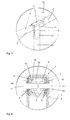
- the internal connector element 6 is inserted, at least partly, in the inner space 2a of an end 2b of the first frame pipe part 2.
- the end 2b of the first frame pipe part 2 including the internal connector element 6 is inserted in the inner space 3a of the end 3b of the second frame pipe part 3.
- the frame pipe part ends 2a, 3a may have a substantially square transversal cross sectional shape (see Figs. 2 and 3 ).
- the respective ends 2a, 3a of the frame pipe parts 2, 3 are provided with at least one opening 8, in the shown embodiment with two opposing openings 8.
- the internal connector element 6 also comprises two opposing openings 9 that are positioned opposite the openings 8 of the first frame pipe part end 2a.
- the openings 9 of the internal connector element 6 are provided with securing members 10, in the shown embodiment, provided at an inner surface 2c (see Figs. 3 and 4 ) of the internal connecting element 6.
- the securing members 10 are formed by a nut having an inner thread that is mounted to the body 6a of the internal connector element 6, which nut is configured to cooperate with the connecting pin 11 to secure the respective parts of the connector 1 and the pipe parts 2, 3 tightly to each other. Therefore, the connecting pin 11 is provided with an external thread that cooperates with the internal thread of the securing member 10.
- the body 6a of the internal connector element 6 has a substantially elongate shape (see Fig.
- the body 6a is formed by an elongate strip material that is bent in a U-shape.
- the legs 12 of the internal connector element 6 extend from the first end 6b of the body 6a towards a second end 6c of the body 6a.
- the internal connector element 6 is provided with a retainer 13.
- the retainer 13 comprises multiple protrusions 14 that extend outward from the perimeter edge 2e of the first frame pipe part end (2a), seen in a transversal cross sectional direction (indicated with arrow A in Fig. 3 ). The retainer 13 prevents the internal connector element 6 from being inserted too far in the frame pipe part 2.
- two spring members 15 are provided at the second end 6c of the body 6a of the internal connector element 6.
- these spring members 15 are formed by the outwardly extending extremities 16 of the respective legs 12 in combination with the legs 12 that behave as leaf springs.
- the first frame pipe part end 2b has a substantially conical shape, i.e. tapers towards the perimeter edge 2e.
- the spring members 15 are biased such that the internal connector element 6 is retracted automatically in the correct predetermined positioned inside the inner space 2b of the first frame pipe part end 2a since the spring members 15 will react against the conical inner wall of the frame pipe part end 2b when the connector element 6 is inserted in said pipe part end 2a and almost reaches said predetermined end position.
- the elongate body 6a of the internal connector element 6 has rounded edges 17 (seen in transversal cross sectional direction (indicated with arrow A in Fig. 4 ) that cooperate with the inner corners 18 of the first frame pipe part 2 (see Fig. 2 ).
- a withdrawal member 19 is provided for enabling easy removal of the inserted internal connector element 6 from the inner space 2b of the first frame pipe part 2.
- the withdrawal member 19 comprises an opening that enables inserting a retractor (not shown) to retract the inserted internal connector element 6 in direction B (see Fig. 3 ).
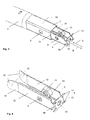
- the external connector element 7 (see Figs. 1 , 5, 6 and 7 ) is configured to cooperate with the internal connector element 6. Therefore, the external connector element 7 comprises at least one opening 20, in the shown embodiment two opposing openings 20 for receiving the connecting pin 11 (see also Fig. 2 ). In the mounted position of the external connector element 7, the openings 20 are provided opposite the corresponding openings 8, 9 of the pipe parts 2, 3 and the internal connector element 6. After inserting the first frame pipe part end 2a in the second frame pipe part end 3a, the external connector element 7 is provided to enclose the pipe part ends 2a, 3a.
- each pin 11 is inserted in the respective openings 20 of the external connector element 7, wherein each pin 11 subsequently extends through said opening 20, the openings 8 provided in the second frame pipe part end 3a and in the first frame pipe part end 2a and through the opening 9 in the internal connector element 6.
- the connecting pin 11 is tightened by inserting the external thread of the pin 11 into the internal thread of the securing member 10. By doing so, the internal connector element 6 and the external connector element 7 are drawn towards each other, thereby clamping both frame pipe part ends 2a, 3a in between.
- the external connector element 7 has a substantially T-shaped body 7a (see Fig. 6 ).
- the T-shaped body 7a has a first receiving section 21 having two opposing ends 21a, 21b configured for receiving the respective ends 2a, 3a of the frame pipe parts 2, 3 and a second receiving section 22 that is arranged substantially perpendicular to the first receiving section 21 such that a third end 22a of the body 7a extends away from the first receiving section 21 and is configured to receive a further frame pipe end 23a (see Figs. 1 and 5 ) for instance of a frame leg 23.
- the third end 22a of the body 7a is formed by two substantially elongate parts 24 that are curved along the entire length of said parts 24 (i.e. seen in a direction parallel to a central axis C of the second receiving section 22).
- the elongate parts 24 each have to longitudinally extending edges 25, 26, that are serrated.
- the serrated edges 25, 26 are configured to cooperate with each other such that upon tightening of another connecting pin 27, that extends through a further opening 28 (see Fig. 6 ) provided in the external connector element 7 at a distance of the first openings 20, the serrated edges 25 of one of the parts 24 engage with the serrated edges 26 of the other one of the parts 24 to form a substantially closed pipe end (see Fig. 5 ).
- the serrated edges 25, 26 prevent displacement of the parts 24 with respect to each other in longitudinal direction.
- the external connector element 7 is provided with reinforcements 29 that are provided in a transitional area 30 between the first receiving section 21 and the second receiving section 22.
- the reinforcements 29 enhance the stiffness of the external connector element 7 and thus of the entire connector 1 according to the invention.
- the reinforcements 29 are forced against at least the second frame pipe part end 3a (indicated by arrow E in Fig. 7 ). This results in the frame pipe part 3 being impressed thereby removing any clearance between the separate parts of the connector 1 as a result of what the connector 1 provides a solid, stiff connection between the different frame pipe parts.
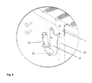
- the external connector element 7 may be provided with an adapter 31 (see Fig. 8 ) that may be mounted to said element 7 and comprise a further receiving section 32 for receiving a frame pipe part of for instance a trampoline safety net.
- the adapter 31 may be removably connected or may be, together with the external connector element 7 be integrally formed as a single piece.
- the adapter 31 may comprise further coupling means 33 for instance for connecting other trampoline parts thereto, for instance a safety net.
- the adapter 31 and the connector 1, at least the external connector element 7 may be integrally formed as a single piece, for instance depending on the manufacturing method used to manufacture the connector 1.
- the internal connector element and/or the external connector element are/is of a different construction.
- the shape and/or dimensions of said elements may vary as long as the elements are configured to cooperate in the manner as above described.
- the securing member may comprise different elements to secure the connecting pin tightly in the openings provided in the internal connector element.
- the connecting pin may have different constructions as long as the securing member and the connecting pin are configured for being interconnected to clamp the respective frame pipe part ends there between.
- the different connector parts may be of different materials and may be manufactured in different ways.
- any reference signs placed between parentheses shall not be construed as limiting the claim.
- the word 'comprising' does not exclude the presence of other features or steps then those listed in a claim.
- the words 'a' and 'an' shall not be construed as limited to 'only one', but instead are used to mean 'at least one', and do not exclude a plurality.
- the mere fact that certain measures are recited in mutually different claims does not indicate that a combination of these measures cannot be used to advantage.
Landscapes
- Engineering & Computer Science (AREA)
- General Engineering & Computer Science (AREA)
- Mechanical Engineering (AREA)
- Health & Medical Sciences (AREA)
- General Health & Medical Sciences (AREA)
- Physical Education & Sports Medicine (AREA)
- Mutual Connection Of Rods And Tubes (AREA)
Applications Claiming Priority (1)
| Application Number | Priority Date | Filing Date | Title |
|---|---|---|---|
| NL2010122A NL2010122C2 (en) | 2013-01-14 | 2013-01-14 | Trampoline frame pipe connector for interconnecting two frame pipe parts of a trampoline. |
Publications (2)
| Publication Number | Publication Date |
|---|---|
| EP2754901A2 true EP2754901A2 (fr) | 2014-07-16 |
| EP2754901A3 EP2754901A3 (fr) | 2016-10-12 |
Family
ID=48483141
Family Applications (1)
| Application Number | Title | Priority Date | Filing Date |
|---|---|---|---|
| EP14150934.9A Withdrawn EP2754901A3 (fr) | 2013-01-14 | 2014-01-13 | Raccord de conduite de châssis de trampoline destiné à relier deux parties de tuyau d'un trampoline |
Country Status (2)
| Country | Link |
|---|---|
| EP (1) | EP2754901A3 (fr) |
| NL (1) | NL2010122C2 (fr) |
Cited By (5)
| Publication number | Priority date | Publication date | Assignee | Title |
|---|---|---|---|---|
| EP3112001A1 (fr) * | 2015-06-29 | 2017-01-04 | Kogee Outdoor Group | Connexion en croix pour cadre de trampoline |
| CN110792727A (zh) * | 2018-08-02 | 2020-02-14 | 安格恩Ag金属成型技术公司 | 用于蹦床的固定装置的锚链钩 |
| CN111803859A (zh) * | 2019-04-11 | 2020-10-23 | 朱国一 | 一种跳床保护网管安装结构 |
| CN111803858A (zh) * | 2019-04-11 | 2020-10-23 | 朱国一 | 一种新型固定结构 |
| EP4190409A1 (fr) * | 2021-12-03 | 2023-06-07 | Acon Finland Oy Ltd | Structure de joint pour relier deux tubes de cadre dans un équipement sportif |
Citations (1)
| Publication number | Priority date | Publication date | Assignee | Title |
|---|---|---|---|---|
| WO2012003636A1 (fr) | 2010-07-06 | 2012-01-12 | Liu Yunwei | Structure de raccord de tuyau de cadre pour un trampoline |
Family Cites Families (3)
| Publication number | Priority date | Publication date | Assignee | Title |
|---|---|---|---|---|
| CH397166A (de) * | 1962-09-07 | 1965-08-15 | Menziken Aluminium Ag | Schnappvorrichtung zur gegenseitigen Verbindung zweier Rohre, insbesondere zweier rohrförmiger Zeltstangen |
| US6565279B1 (en) * | 2002-01-14 | 2003-05-20 | Kiefer Pool Equipment Co. | Clamp for pipes or for other cylindrical struts |
| US7066676B2 (en) * | 2004-05-04 | 2006-06-27 | Ming-Liang Tsai | Locating device for a retractable strut of a tent or a closet |
-
2013
- 2013-01-14 NL NL2010122A patent/NL2010122C2/en active
-
2014
- 2014-01-13 EP EP14150934.9A patent/EP2754901A3/fr not_active Withdrawn
Patent Citations (1)
| Publication number | Priority date | Publication date | Assignee | Title |
|---|---|---|---|---|
| WO2012003636A1 (fr) | 2010-07-06 | 2012-01-12 | Liu Yunwei | Structure de raccord de tuyau de cadre pour un trampoline |
Cited By (7)
| Publication number | Priority date | Publication date | Assignee | Title |
|---|---|---|---|---|
| EP3112001A1 (fr) * | 2015-06-29 | 2017-01-04 | Kogee Outdoor Group | Connexion en croix pour cadre de trampoline |
| CN110792727A (zh) * | 2018-08-02 | 2020-02-14 | 安格恩Ag金属成型技术公司 | 用于蹦床的固定装置的锚链钩 |
| CN110792727B (zh) * | 2018-08-02 | 2022-10-21 | 安格恩Ag金属成型技术公司 | 用于蹦床的固定装置的锚链钩 |
| CN111803859A (zh) * | 2019-04-11 | 2020-10-23 | 朱国一 | 一种跳床保护网管安装结构 |
| CN111803858A (zh) * | 2019-04-11 | 2020-10-23 | 朱国一 | 一种新型固定结构 |
| EP4190409A1 (fr) * | 2021-12-03 | 2023-06-07 | Acon Finland Oy Ltd | Structure de joint pour relier deux tubes de cadre dans un équipement sportif |
| US12215736B2 (en) | 2021-12-03 | 2025-02-04 | Acon Finland Oy Ltd | Joint structure for connecting two frame tubes in sporting equipment |
Also Published As
| Publication number | Publication date |
|---|---|
| EP2754901A3 (fr) | 2016-10-12 |
| NL2010122C2 (en) | 2014-07-15 |
Similar Documents
| Publication | Publication Date | Title |
|---|---|---|
| EP2754901A2 (fr) | Raccord de conduite de châssis de trampoline destiné à relier deux parties de tuyau d'un trampoline | |
| KR101683146B1 (ko) | 원터치식 철근 커플러 | |
| JP5143572B2 (ja) | 連結装置 | |
| JP4276196B2 (ja) | 車両用ルーフアンテナ取付け装置 | |
| JP5168694B2 (ja) | クリップ | |
| KR101509920B1 (ko) | 알루미늄 프로파일의 연결구 구조 | |
| KR101906169B1 (ko) | 철근 이음용 커플러 | |
| WO2016024601A1 (fr) | Structure de montage d'antenne montee sur le toit | |
| JP2016096001A (ja) | ワイヤハーネスおよびワイヤハーネスの製造方法 | |
| KR20180124662A (ko) | 파형관 연결장치 | |
| KR102652961B1 (ko) | 체결 장치 및 체결 어셈블리 | |
| CN114607690A (zh) | 一种用于固定零部件的紧固装置及紧固组件 | |
| CN100414161C (zh) | 用于固定和连接管子的管夹 | |
| CN100559033C (zh) | 弹簧螺母 | |
| KR20210000863U (ko) | 철근 연결용 나사식 원터치 커플러 | |
| KR20110043200A (ko) | 파이프 고정용 클램프 | |
| KR101430366B1 (ko) | 비닐하우스용 비닐 고정패드 | |
| CN211421488U (zh) | 隔墙龙骨安装结构 | |
| KR101661589B1 (ko) | 안내판 걸이구 | |
| CN108173182B (zh) | 电力管的管枕 | |
| CN107906256B (zh) | 一种管夹 | |
| JP2009509108A (ja) | 縦長の対象装置を保持する装置 | |
| KR20190116490A (ko) | 체결 장치 및 체결 어셈블리 | |
| JP7277914B2 (ja) | フェライトクランプの固定具 | |
| KR20180124660A (ko) | 파형관 연결장치 |
Legal Events
| Date | Code | Title | Description |
|---|---|---|---|
| PUAI | Public reference made under article 153(3) epc to a published international application that has entered the european phase |
Free format text: ORIGINAL CODE: 0009012 |
|
| 17P | Request for examination filed |
Effective date: 20140113 |
|
| AK | Designated contracting states |
Kind code of ref document: A2 Designated state(s): AL AT BE BG CH CY CZ DE DK EE ES FI FR GB GR HR HU IE IS IT LI LT LU LV MC MK MT NL NO PL PT RO RS SE SI SK SM TR |
|
| AX | Request for extension of the european patent |
Extension state: BA ME |
|
| PUAL | Search report despatched |
Free format text: ORIGINAL CODE: 0009013 |
|
| AK | Designated contracting states |
Kind code of ref document: A3 Designated state(s): AL AT BE BG CH CY CZ DE DK EE ES FI FR GB GR HR HU IE IS IT LI LT LU LV MC MK MT NL NO PL PT RO RS SE SI SK SM TR |
|
| AX | Request for extension of the european patent |
Extension state: BA ME |
|
| RIC1 | Information provided on ipc code assigned before grant |
Ipc: F16B 7/04 20060101AFI20160907BHEP |
|
| STAA | Information on the status of an ep patent application or granted ep patent |
Free format text: STATUS: THE APPLICATION IS DEEMED TO BE WITHDRAWN |
|
| 18D | Application deemed to be withdrawn |
Effective date: 20170413 |