EP2754932B1 - Ventileinsatzanordnung und ventil mit der ventileinsatzanordnung - Google Patents
Ventileinsatzanordnung und ventil mit der ventileinsatzanordnung Download PDFInfo
- Publication number
- EP2754932B1 EP2754932B1 EP12830728.7A EP12830728A EP2754932B1 EP 2754932 B1 EP2754932 B1 EP 2754932B1 EP 12830728 A EP12830728 A EP 12830728A EP 2754932 B1 EP2754932 B1 EP 2754932B1
- Authority
- EP
- European Patent Office
- Prior art keywords
- valve
- valve core
- rod
- core assembly
- ejector pin
- Prior art date
- Legal status (The legal status is an assumption and is not a legal conclusion. Google has not performed a legal analysis and makes no representation as to the accuracy of the status listed.)
- Not-in-force
Links
- 230000005540 biological transmission Effects 0.000 claims description 61
- 238000007789 sealing Methods 0.000 description 12
- 230000009471 action Effects 0.000 description 7
- 238000000034 method Methods 0.000 description 4
- 230000008878 coupling Effects 0.000 description 3
- 238000010168 coupling process Methods 0.000 description 3
- 238000005859 coupling reaction Methods 0.000 description 3
- 230000008569 process Effects 0.000 description 3
- 239000002131 composite material Substances 0.000 description 2
- 238000004519 manufacturing process Methods 0.000 description 2
- 230000007246 mechanism Effects 0.000 description 2
- 238000005728 strengthening Methods 0.000 description 2
- 235000008331 Pinus X rigitaeda Nutrition 0.000 description 1
- 235000011613 Pinus brutia Nutrition 0.000 description 1
- 241000018646 Pinus brutia Species 0.000 description 1
- 238000004873 anchoring Methods 0.000 description 1
- 238000010276 construction Methods 0.000 description 1
- 230000000694 effects Effects 0.000 description 1
- 238000005516 engineering process Methods 0.000 description 1
- 230000036316 preload Effects 0.000 description 1
- 238000000926 separation method Methods 0.000 description 1
- 238000004904 shortening Methods 0.000 description 1
- 238000003466 welding Methods 0.000 description 1
Images




Classifications
-
- F—MECHANICAL ENGINEERING; LIGHTING; HEATING; WEAPONS; BLASTING
- F16—ENGINEERING ELEMENTS AND UNITS; GENERAL MEASURES FOR PRODUCING AND MAINTAINING EFFECTIVE FUNCTIONING OF MACHINES OR INSTALLATIONS; THERMAL INSULATION IN GENERAL
- F16K—VALVES; TAPS; COCKS; ACTUATING-FLOATS; DEVICES FOR VENTING OR AERATING
- F16K5/00—Plug valves; Taps or cocks comprising only cut-off apparatus having at least one of the sealing faces shaped as a more or less complete surface of a solid of revolution, the opening and closing movement being predominantly rotary
- F16K5/06—Plug valves; Taps or cocks comprising only cut-off apparatus having at least one of the sealing faces shaped as a more or less complete surface of a solid of revolution, the opening and closing movement being predominantly rotary with plugs having spherical surfaces; Packings therefor
- F16K5/0647—Spindles or actuating means
-
- F—MECHANICAL ENGINEERING; LIGHTING; HEATING; WEAPONS; BLASTING
- F16—ENGINEERING ELEMENTS AND UNITS; GENERAL MEASURES FOR PRODUCING AND MAINTAINING EFFECTIVE FUNCTIONING OF MACHINES OR INSTALLATIONS; THERMAL INSULATION IN GENERAL
- F16K—VALVES; TAPS; COCKS; ACTUATING-FLOATS; DEVICES FOR VENTING OR AERATING
- F16K5/00—Plug valves; Taps or cocks comprising only cut-off apparatus having at least one of the sealing faces shaped as a more or less complete surface of a solid of revolution, the opening and closing movement being predominantly rotary
- F16K5/08—Details
- F16K5/14—Special arrangements for separating the sealing faces or for pressing them together
- F16K5/20—Special arrangements for separating the sealing faces or for pressing them together for plugs with spherical surfaces
-
- F—MECHANICAL ENGINEERING; LIGHTING; HEATING; WEAPONS; BLASTING
- F16—ENGINEERING ELEMENTS AND UNITS; GENERAL MEASURES FOR PRODUCING AND MAINTAINING EFFECTIVE FUNCTIONING OF MACHINES OR INSTALLATIONS; THERMAL INSULATION IN GENERAL
- F16K—VALVES; TAPS; COCKS; ACTUATING-FLOATS; DEVICES FOR VENTING OR AERATING
- F16K5/00—Plug valves; Taps or cocks comprising only cut-off apparatus having at least one of the sealing faces shaped as a more or less complete surface of a solid of revolution, the opening and closing movement being predominantly rotary
- F16K5/08—Details
- F16K5/14—Special arrangements for separating the sealing faces or for pressing them together
- F16K5/20—Special arrangements for separating the sealing faces or for pressing them together for plugs with spherical surfaces
- F16K5/204—Special arrangements for separating the sealing faces or for pressing them together for plugs with spherical surfaces with the plugs or parts of the plugs mechanically pressing the seals against the housing
Definitions
- the invention relates to a valve core assembly and a valve adopting the valve core assembly, specifically relates to an internal or external low torque valve for composite intermediate bulk containers (IBC).
- IBC composite intermediate bulk containers
- the composite intermediate bulk containers (IBC) are provided with valves, such as the butterfly valve disclosed in WO2007/030052 A1 , however, its sealing performance is not desirable and leakage may be occurred easily.
- One of such external valves is DN50 ball valve; however, the valve has disadvantages that the torque is large, difficult to operate, too many components, and high cost.
- Chinese patent No. 200720082066 disclosed a low torque ball valve, which provides a low torque valve comprising a valve body, a valve ball, a valve seat, a bearing seat, a valve stem, a driving means, and a valve ball bearing connection.
- the patent has several disadvantages.
- the structure of the driving device is complex, and extremely occupies the external space of the valve body.
- the driving device involves many parts, resulting in the complexity of the assembling process.
- the rotation angle for opening or closing the valve is 180 degrees.
- the working space formed by the valve rod and the driving device requires a very high quality of sealing process, thus the traditional sealing methods and processes are likely to cause leakage.
- the cost of manufacturing the driving device is very high, it does not conform to the purpose for economy and environment friendly.
- Chinese Patent Application No. 99124192.4 disclosed a structure for opening and closing a valve, which is a disk-shaped two-track rotary with deploy-close structure.
- the structure comprises a fixed disk, a rotating disk and a stop pin.
- the stop pin rotates clockwise along the "arc" track of the fixed disk.
- the rotating disk rotates clockwise further, and the stop pin deploys the surrounding of the fixed disk along the "straight" track of the fixed disk under the forced action by the "deploy-close” track of the rotating disk.
- the stop pin structure together with the valve sealing structure close to the valve seat, thus close the valve.
- Chinese Patent No. 200620105067 disclosed an orbit plug valve, comprising a valve body, a valve cover, an operating member, a valve rod, a valve seat, a valve plug which together with the valve seat forming a conical surface sealing, and an orbital mechanism.
- the orbital mechanism comprises a track with two guide slots mounting on the neck portion of the valve plug and a plate with two guide pins inserting into said guide slots, as well as a lock nut and an adjusting ring for adjusting the mounting position of the track.
- the shortcomings of the present patent are that the transmission device structure is complex, and extremely occupy the external space of the valve body. Further, the transmission device involves more parts, resulting in complicated assembly process.
- the valve since the valve has a plug forming a cone surface sealing as well as a lock nut and an adjusting ring for adjusting the mounting position of the track, it must be adjusted several times, resulting in complex operation.
- the document CN 201 902 691 U describes a further valve core assembly relevant to the subject-matter of claim 1.
- the object of the invention is to provide a valve core assembly and a valve adopting the valve core assembly, which have advantages that the torque is small when open the valve, the structure is simple, easy to operate, and the sealing performance is desirable.
- the disclosure provide a valve core assembly disposed in a valve body and being rotatable about a common axis upon engaging with the valve body, the valve core assembly comprising a valve core, a valve rod and a transmission member having the common axis, wherein: further comprises a sliding ejector pin arranged along an axis perpendicular to the common axis; the valve core has one concave portion; the transmission member is combined with the valve rod at the end of the valve rod and is able to rotate along with the valve rod; the transmission member is at least partially placed inside the concave portion; a radial inwardly-convex profile is formed at the circumferential wall inside the concave portion; the transmission member is formed with a radial outwardly-convex profile; a valve rod cavity is provided radially on the end of the valve rod for accommodating the sliding ejector pin; an inwardly-convex profile is provided on the valve body for surrounding the valve rod; when rotating the valve rod, the
- the sliding ejector pin comprises a pin body, a sliding pin and a projection, the sliding pin and the projection being perpendicular to the pin body and extending from both ends of the pin body respectively in opposing direction, the sliding ejector pin being placed in the valve rod cavity, and there is a detachable relationship between the projection of the sliding ejector pin and the radial inwardly-convex profile formed at the circumferential wall inside the concave portion of the valve core.
- the radial inwardly-convex profile formed at the circumferential wall inside the concave portion of the valve core is provided with at least two pits and a projection separating the two pits; one of the two pits and the projection detachably engage with the radial outwardly- convex profile of the transmission member, the other of the two pits detachably engages with the projection of the sliding ejector pin.
- valve rod is formed with a transmission rod and a support portion being extended coaxially from the lower end of the transmission rod, the transmission member being further provided with a transmission hole for engaging with the transmission rod, the concave portion being further provided with an elongate positioning hole for engaging with the support portion.
- the support portion is a cylindrical member, the elongate positioning hole being an elongate hole having two parallel sides and two arc-shaped ends.
- the transmission rod is a splined rod, the transmission hole being a splined hole for engaging with the splined rod.
- the sliding pin of the sliding ejector pin is a cylinder, the projection of the sliding ejector pin being an elongate body, and the side of the elongate body engaging with the pit is an arc surface.
- the radial outwardly-convex profile of the transmission member is generally in form of rectangular whose two axial corners are rounded or chambered.
- the disclosure provides a valve comprising a valve body, a positioning rod, a valve seat, a valve core assembly, the valve body comprising: an inlet and an outlet having a common horizontal axis, an inner space being formed between the inlet and the outlet for accommodating the valve core assembly, the valve seat being placed on the inner side of the inlet; a valve rod hole and a bottom hole formed on the top end wall and the bottom end wall of the valve body along a vertical axis perpendicular to the horizontal axis; a part of the valve core assembly passes through the valve rod hole, the positioning rod hermetically accommodated in the bottom hole, the valve core assembly being able to rotate around the vertical axis, such that the valve core detachably hermetically engage with the valve seat, wherein: the valve core assembly is the valve core assembly described above; when the valve rod drives the sliding ejector pin and the transmission member to rotate, the radial inwardly-convex profile in the concave portion of the valve core engages with the sliding
- the valve is a ball valve.
- valve core When the projection of the sliding ejector pin is positioned partly in the pit of the concave portion, a gap exit between the valve core and valve seat and the valve is opened, thus the valve core may be driven by the valve rod through the sliding ejector pin to rotate around the positioning rod; when the valve core is rotated to a pre-closed position, since the position limiting and stopping projections provided on the bottom of the valve core and the position limiting and stopping blocks provided on the bottom of the valve body, the valve core 4 may only be rotated within 90 degrees inside the valve body, thus the valve core will be not rotated along with the valve rod any more.
- the sliding ejector pin which is positioned partly in the pit of the concave portion will be moved under the action of the inwardly-convex profile provided on of the valve rod hole of the valve body, such that the portion of the sliding ejector pin which is positioned in the pit of the concave portion leaves the pit, causing the valve rod to move relative to the valve core.
- the radial outwardly-convex profile of the transmission member and the projection of the concave portion of the valve core squeeze with each other as the transmission member is driven by the valve rod.
- the valve core can rotate axially around the positioning rod and move radially, the axial rotation leading to open or close the valve, the radial movement leading to achieve sealing.
- valve core assembly and valve adopting the valve core assembly not only has a low opening and closing torque and excellent sealing performance, but also has a simple structure, a high space utilization, fewer parts and easy to manufacture.
- the valve rod is a part used to control the movement of the valve core
- the transmission device is a device used to transfer the operation intent of the operator for operating the valve core, where the operation intent is to realize the opening and the closing of the valve through rotating the valve rod.
- a valve according to one embodiment comprises a valve body 1, a valve rod 2, a positioning rod 3, a valve core 4, a valve seat 5, a sliding ejector pin 6 and a transmission member 7.
- the valve body 1, the valve rod 2, the positioning rod 3 and the transmission member 7 have a common axis, and the valve core 4, the valve rod 2, the sliding ejector pin 6 and a transmission member 7 make up the valve core assembly.
- valve body 1 is a housing having a top end and bottom end as well as left and right sides. There is an inner space formed in the housing for accommodating the valve core 4, transmission member 7 and part of the valve rod and the sliding ejector pin.
- An inlet 1a and an outlet 1b are formed on the left side and right side along a horizontal axis (not shown), respectively.
- the inlet 1a and the outlet 1b are communicated to a container and external, respectively.
- the valve seat 5 is provided along the horizontal axis at the inner side of the inlet 1a.
- the top end wall and the bottom end wall of the valve body 1 are formed with a valve rod hole 2b and a bottom hole 10 along a vertical axis (not shown) perpendicular to the horizontal axis, respectively.
- position limiting and stopping blocks 1d, 1c are provided on the bottom of the valve body 1 at two sides of the bottom hole 10 along its radial direction.
- the position limiting and stopping blocks 1d, 1c are engaged with the limiting and stopping projection of valve core respectively (which will be described in more detail in the following), such that the valve core 4 may only rotate within 90 degrees in the valve body 1.
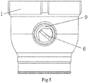
- a radial inwardly-convex profile 9 is formed on the inner wall of the valve rod hole 2b at the bottom of the valve rod hole 2b, as shown in Fig 2 and 5 .
- valve rod 2 is rotatably accommodated in the valve rod hole 2b.
- the positioning rod 3 is accommodated in the bottom hole 10 of the valve body.
- the lower portion of the positioning rod 3 is secured to the wall of the bottom hole 10 through a seal ring, the upper portion of the positioning rod 3 extends out of the bottom hole 10, thus engages with the supporting hole of the valve core (which will be further described hereafter).
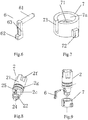
- the structure of the valve rod 2 is shown in Fig. 3 , Fig.8 and Fig.9 , wherein a cross head 2f is formed on the upper portion of the valve rod 2, on which a handle 8. At least one angular slot 2g is provided on the circumference of the valve rod 2 at its middle portion (two slots in the drawing).
- a sealing ring is placed in the angular slot 2g so as to achieve the sealing between the wall of the valve rod hole 2b and the valve rod 2.
- a radial hole 25 is provided on the valve rod 2 below the angular slot 2g (that is, the end of the valve rod), as shown in Fig.8 . It should be noted that the radial hole 25 may be provided on the end of the valve rod at any position along its axis.
- a cross slot 2c extending downwardly from one end of the hole 25 is provided on the external wall, the cross slot 2c being constructed of a horizontal slot and a axial slot perpendicular to the horizontal slot, the axial slot extending to the lower end face of the middle portion of the valve rod.
- the lower portion of the valve rod 2 is formed with a transmission rod 22.
- the transmission rod 22 is a splined rod 22, and a support portion 24 being extended coaxially from the lower end face of the splined rod 22.
- the support portion 24 is a cylindrical member, in this embodiment, the support portion 24 is a cylindrical whose cross-section is circular. However, those skilled in the art should be understood that the cross section of the support portion 24 may be triangular, square, etc.
- Figs. 6 and 9 show a specific structure of the sliding ejector pin 6, as shown, the sliding ejector pin 6 comprises a pin body 63, and a sliding pin 61 and a projection 62, the sliding pin 61 and the projection 62 being perpendicular to the pin body and extending from both ends of the pin body respectively in opposing direction.
- the sliding pine 61 is positioned in the radial hole 25, and the distal end of the sliding pin 61 abuts against the inwardly-convex profile of the valve body, as shown in Figs. 2 and 5 .
- the sliding pin 61 is a cylinder whose cross-section is circular in this embodiment.
- the cross-section of the sliding pin 61 may be circular, oval, hexagonal and any suitable shape depending on needs.
- the projection 62 is an elongate body in the present embodiment, the cross section of which is a rectangular; the side engaging with the concave portion of the valve core 4 is an arc surface (which will be described below). It should be understood for the skilled person that the projections 62 may be an elongate body whose cross section is a circular, a polygonal and the like.
- Fig. 7 shows a specific construction of the transmission member 7.
- the transmission member 7 is a cylindrical having a bottom and an opening opposing the bottom.
- An inner hole 7a is provided axially inside the transmission member 7 between the opening and the bottom for accommodating the valve rod 2.
- a transmission hole is provided on the bottom which is a splined hole in the embodiment; a radial outwardly-convex profile 72 protruding outwardly is formed on the outer periphery of said bottom.
- the radial outwardly-convex profile is generally in form of rectangular whose two axial corners are rounded or chambered. It should be noted that the radial outwardly-convex profile may be other non-regular shape.
- the radial outwardly-convex profile 72 may engage with the radial inwardly-convex profile provided on the inner wall of the concave portion of the valve core 4(which will be described below).
- the transmission hole 71 is engaged with the transmission rod 22 of the valve rod 2, that is, the splined hole 71 being engaged with the splined rod 22 in the embodiment, which will cause the valve rod 2 to drive the transmission member 7 to rotate.
- An elongate cut 73 extending downwardly from the opening of the inner hole 7a is provided on the out wall of the cylindrical body 7 of the transmission member 7, when the valve rod 2 and the sliding ejector pin 6 assembly is inserted into the inner hole 7a, the pin body 63 and the projection 62 of the sliding ejector pin are just accommodated in the cut 73.
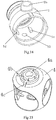
- Fig.10 shows a structure of the valve core 4.
- the valve core 4 in the embodiment is in form of hollow spherical shell and has a vertical axis (not shown).
- a concave portion 40 extending along the vertical axis and a supporting hole 4a are provided on the top and the bottom of the spherical shell respectively.
- a strengthening boss 42 is provided around the concave portion 40 on the top of the valve core so as to have the concave portion 40 with a desired deep, as shown in Fig.1 , however, the strengthening boss 40 may be omitted.
- a radial inwardly-convex profile is formed in the inner wall of the concave portion 40, the radial inwardly-convex profile being provided with at least two pits 44, 46 and a projection 45 separating the two pits.
- One 44 of the two pits and the projection 45 may detachably engage with the radial outwardly- convex profile 72 (projections protruding outwardly) of the transmission member 7; and the other 46 of the two pits may detachably engages with the projection 62 of the sliding ejector pin.
- An elongate positioning hole 41 toward to the projection 45 is formed on the bottom of the concave portion so as to engage with the support portion 24, the elongate positioning hole 41 being an elongate hole having two parallel sides and two arc-shaped ends.
- position limiting and stopping projections 4b, 4c are provided radially on the bottom of the valve core 4 outside the support hole 4a so as to engage with the position limiting and stopping blocks 1d, 1c of the valve body respectively, the angle between the position limiting and stopping projections 4b and 4c is 90 degrees.
- the position limiting and stopping projection 4c engage with the position limiting and stopping blocks 1d so as to prevent the valve core from rotating over 90 degrees.
- the position limiting and stopping projection 4b engage with the position limiting and stopping blocks 1c so as to prevent the valve core from rotating over 90 degrees.
- Figs. 4 and 11 show the relative positions of the valve core 4, the valve rod 2, the sliding ejector pin 6, and the transmission member 7 when the valve is opened.
- the valve core 4 will rotate along with the valve rod 2, since the projection 62 of the sliding ejector pin 6 is positioned in the pit 46 provided on the inner wall of the concave portion 40 of the valve core 4.
- the valve core is rotated to a pre-closed position, as shown in Fig.
- the valve core 4 will be not rotated along with the valve rod 2 any more, since the position limiting and stopping projections 4b, 4c provided on the bottom of the valve core 4 and the position limiting and stopping blocks 1d, 1c provided on the bottom of the valve body 1 cause the valve core 4 to rotate within 90 degrees only inside the valve body.
- the projection 62 of the sliding ejector pin 6 will be moved under the action of the inwardly-convex profile 9 provided on the side wall of the valve rod hole 2b of the valve body 1, and the valve core 4 will not be rotated along with the valve rod 2 as the projection 62 disengaged with the pit 46 provided on the concave portion 40 of the valve core 4.
- the radial outwardly-convex profile of the transmission member 7 and the projection 45 of the valve core 4 squeezes with each other as the transmission member 7 is driven by the valve rod 2.
- the valve core 4 is moved axially along the horizontal axis of the valve body 1 so as to squeeze the valve seat 5, thus achieve a fully closed state, as shown in Fig.13 .
- valve rod 2 When open the valve, the valve rod 2 is rotated reversely, the sliding ejector pin 6 being rotated along with the valve rod 2, and the projection 62 of the sliding ejector pin 6 entering the pit 46 again under the action of the convex profile 9 of the valve body, the radial outwardly-convex profile 72 of the transmission member 7 being disengaged with the projection 45 of the valve core 4, thus the rotation of the valve rod 2 will cause the valve core to rotate, resulting opening the valve.
- the embodiments described above is a ball valve, however, the structure of the present invention may also be applied to the other valve, e.g. butterfly valve.
- the members of the invention may adopt other configuration without departing from the spirit of the invention.
- the handle 8 and the valve rod 2 may be separated part or integrated part.
- the configuration of the sliding ejector pin may be other sliding ejector pin which may engage with the valve rod 2 and concave portion 40 so as to achieve separation and reunion function.
- the coupling between the valve rod and the transmission member may adopt splined coupling, or screw coupling, anchoring, welding and other forms which are known to the person skilled in the art.
Landscapes
- Engineering & Computer Science (AREA)
- General Engineering & Computer Science (AREA)
- Mechanical Engineering (AREA)
- Mechanically-Actuated Valves (AREA)
- Sliding Valves (AREA)
Claims (11)
- Ventilkernanordnung, die in einem Ventilgehäuse (1) angeordnet ist, und die um eine gemeinsame Achse herum rotierbar ist, wenn sie mit dem Ventilgehäuse (1) einrastet, wobei die Ventilkernanordnung einen Ventilkern (4), einen Ventilstab (2) und ein Übertragungselement (7), das die gemeinsame Achse aufweist, umfasst und weiter einen gleitenden Auswurfpin (6) umfasst, der entlang einer Achse rechtwinklig zu der gemeinsamen Achse angeordnet ist;
wobei der Ventilkern (4) einen konkaven Anteil (40) aufweist; das Übertragungselement (7) mit dem Ventilstab (2) an dem Ende des Ventilstabs (2) kombiniert ist und fähig ist zusammen mit dem Ventilstab (2) zu rotieren; das Übertragungselement (7) zumindest teilweise innerhalb des konkaven Anteils (40) platziert ist; ein radial nach innen konvexes Profil (9) an der Umfangswand innerhalb des konkaven Anteils (40) gebildet ist; das Übertragungselement (7) mit einem radial nach außen konvexen Profil (72) gebildet ist; eine Ventilstabaushöhlung radial an dem Ende des Ventilstabs (2) bereitgestellt ist, um den gleitenden Auswurfpin (6) aufzunehmen; ein nach innen konvexes Profil auf dem Ventilgehäuse (1) bereitgestellt ist, um den Ventilstab (2) zu umgeben;
wenn der Ventilstab (2) rotiert, grenzt das nach innen konvexe Profil des Ventilgehäuses (1) an den gleitenden Auswurfpin (6) an und treibt den gleitenden Auswurfpin (6) an, um sich radial in dem Ventilstabhohlraum zu bewegen; wenn der gleitende Auswurfpin (6) sich radial in dem Ventilstab (2) bewegt bis das nach innen konvexe Profil des Ventilgehäuses (1) den gleitenden Auswurfpin (6) antreibt, um sich von dem Ventilkern (4) zu trennen, rastet das nach außen konvexe Profil (72) des Übertragungselements (7) bei dem Ende des Ventilstabs (2) mit dem radial nach innen konvexen Profil (9) des konkaven Anteils (40) des Ventilkerns (4) ein, sodass die Rotation des Übertragungselements (7) um die gemeinsame Achse herum in eine radiale Bewegung umgewandelt wird, die den Ventilkern (4) veranlasst, sich gegen den Ventilsitz (5) des Ventilgehäuses (1) zu drücken. - Ventilkernanordnung nach Anspruch 1, wobei der gleitende Auswurfpin (6) ein Pingehäuse (63), einen gleitenden Pin (61) und einen Vorsprung (62) umfasst, wobei der gleitende Pin (61) und der Vorsprung (62) rechtwinklig zu dem Pingehäuse (63) sind und sich von beiden Enden des Pingehäuses (63) jeweils in entgegengesetzte Richtungen erstrecken, wobei der gleitende Auswurfpin (6) in der Ventilstabaushöhlung platziert wird und es eine trennbare Verbindung zwischen dem Vorsprung (62) und dem gleitenden Auswurfpin (6) und dem radial nach innen konvexen Profil (9) gibt, das an der Umfangswand innerhalb des konkaven Anteils (40) des Ventilkerns (4) gebildet ist.
- Ventilkernanordnung nach Anspruch 2, wobei das radial nach innen konvexe Profil (9), das an der Umfangswand innerhalb des konkaven Anteils (40) des Ventilkerns (4) gebildet ist, mit mindestens zwei Vertiefungen (44, 46) und einem Vorsprung (45) bereitgestellt ist, der die zwei Vertiefungen (44, 46) trennt; und wobei eine von den zwei Vertiefungen (44) und von dem Vorsprung (45) trennbar mit dem radial nach außen konvexen Profil (72) des Übertragungselements (7) einrastet, und wobei die andere der zwei Vertiefungen (46) trennbar mit dem Vorsprung (62) des gleitenden Auswurfpins (6) einrastet.
- Ventilkernanordnung nach Anspruch 1, wobei der Ventilstab (2) mit einem Übertragungsstab (22) und einem Unterstützungsanteil (24) gebildet ist, der sich koaxial von dem unteren Ende des Übertragungsstabs (22) erstreckt, wobei das Übertragungselement (7) weiter mit einem Übertragungsloch (71) zum Einrasten mit der Übertragungsstange (22) bereitgestellt ist, wobei der konkave Anteil (40) weiter mit einem länglichen Positionierungsloch (41) bereitgestellt wird, um mit dem Unterstützungsanteil (24) einzurasten.
- Ventilkernanordnung nach Anspruch 4, wobei der Unterstützungsanteil (24) ein zylindrisches Element ist, wobei das längliche Positionierungsloch (41) ein längliches Loch ist, das zwei parallele Seiten und zwei bogenförmige Enden aufweist.
- Ventilkernanordnung nach Anspruch 4, wobei der Übertragungsstab (22) ein Keilstab ist, wobei das Übertragungsloch (71) ein Keilloch zum Einrasten mit dem Keil stab ist.
- Ventilkernanordnung nach Anspruch 3, wobei der gleitende Pin (61) des gleitenden Auswurfpins (6) ein Zylinder ist, wobei der Vorsprung des gleitenden Auswurfpins (6) ein länglicher Körper ist, und wobei die Seite des länglichen Körpers, die mit der Vertiefung einrastet, eine bogenförmige Oberfläche ist.
- Ventilkernanordnung nach Anspruch 1, wobei das radial nach außen konvexe Profil (72) des Übertragungselements (7) generell die Form eines Rechtecks annimmt, dessen zwei axiale Ecken gerundet oder abgeschrägt sind.
- Ventil, umfassend ein Ventilgehäuse (1), einen Positionierungsstab (3) einen Ventilsitz (5), und eine Ventilkernanordnung, wobei das Ventilgehäuse (1) einen Einlass (1a) und einen Auslass (1b) aufweist, die eine gemeinsame horizontale Achse aufweisen, wobei ein innerer Raum zwischen dem Einlass (1a) und dem Auslass (1b) gebildet ist, um die Ventilkernanordnung aufzunehmen, wobei der Ventilsitz (5) auf der inneren Seite des Einlasses (1a) platziert ist; ein Ventilstabloch (2b) und ein unteres Loch (10), die an der oberen Endwand und der unteren Endwand des Ventilgehäuses (1) entlang einer vertikalen Achse, die rechtwinklig zu der horizontalen Achse ist, gebildet sind; wobei ein Teil der Ventilkernanordnung durch das Ventilstabloch (2b) hindurch verläuft, wobei der Positionierungsstab (3) hermetisch in dem unteren Loch (10) aufgenommen ist, wobei die Ventilkernanordnung fähig ist, um die vertikale Achse herum zu rotieren, sodass der Ventilkern (4) hermetisch entfernbar mit dem Ventilsitz (5) einrastet, wobei:die Ventilkernanordnung die Ventilkernanordnung gemäß einem der Ansprüche 1 bis 8 ist;wenn der Ventilstab (2) den gleitenden Auswurfpin (6) und das Übertragungselement (7) antreibt, um zu rotieren, rastet das radial nach innen konvexe Profil (9) in dem konkaven Anteil (40) des Ventilkerns (4) mit dem gleitenden Auswurfpin (6) und dem radial nach außen konvexen Profil (72) des Übertragungselements (7) ein, um den Ventilkern (4) zwischen einem offenen Zustand, einem vorgeschossenen Zustand und einem vollständig geschlossenen Zustand umzuschalten.
- Ventil nach Anspruch 9, wobei ein Griff (8) an dem oberen Ende des Ventilstabs (2) der Ventilkernanordnung bereitgestellt ist.
- Ventil nach Anspruch 9, wobei das Ventil ein Kugelventil ist.
Applications Claiming Priority (2)
| Application Number | Priority Date | Filing Date | Title |
|---|---|---|---|
| CN2011102608516A CN102322536B (zh) | 2011-09-05 | 2011-09-05 | 阀芯组件及采用该阀芯组件的阀门 |
| PCT/CN2012/078634 WO2013034032A1 (zh) | 2011-09-05 | 2012-07-13 | 阀芯组件及采用该阀芯组件的阀门 |
Publications (3)
| Publication Number | Publication Date |
|---|---|
| EP2754932A1 EP2754932A1 (de) | 2014-07-16 |
| EP2754932A4 EP2754932A4 (de) | 2015-08-05 |
| EP2754932B1 true EP2754932B1 (de) | 2017-03-15 |
Family
ID=45450336
Family Applications (1)
| Application Number | Title | Priority Date | Filing Date |
|---|---|---|---|
| EP12830728.7A Not-in-force EP2754932B1 (de) | 2011-09-05 | 2012-07-13 | Ventileinsatzanordnung und ventil mit der ventileinsatzanordnung |
Country Status (4)
| Country | Link |
|---|---|
| US (1) | US9279505B2 (de) |
| EP (1) | EP2754932B1 (de) |
| CN (1) | CN102322536B (de) |
| WO (1) | WO2013034032A1 (de) |
Families Citing this family (26)
| Publication number | Priority date | Publication date | Assignee | Title |
|---|---|---|---|---|
| CN102322536B (zh) * | 2011-09-05 | 2012-11-07 | 上海鸿润科技有限公司 | 阀芯组件及采用该阀芯组件的阀门 |
| CN102840381B (zh) * | 2012-08-16 | 2014-09-10 | 上海鸿研物流技术有限公司 | 一种用于复合型中型散装容器的阀门启闭装置及容器 |
| CN102808990B (zh) * | 2012-08-16 | 2015-04-29 | 上海鸿研物流技术有限公司 | 用于中型散装容器的阀门启闭装置及容器 |
| CN103016776B (zh) * | 2012-12-07 | 2015-08-26 | 上海鸿研物流技术有限公司 | 阀芯组件及低扭矩阀门 |
| CN103759032B (zh) * | 2014-01-08 | 2017-06-13 | 上海鸿研物流技术有限公司 | 阀门 |
| AT514248B1 (de) * | 2014-07-04 | 2016-05-15 | Avl List Gmbh | Lineares Regelventil |
| EP3169621B1 (de) * | 2014-07-16 | 2021-09-08 | Coloplast A/S | Auslass für eine urostomievorrichtung |
| USD734431S1 (en) * | 2014-07-25 | 2015-07-14 | Champ-Air Refrigeration Hardware Co., Ltd. | Tube expander |
| CN104595517B (zh) * | 2014-12-31 | 2017-02-08 | 上海鸿研物流技术有限公司 | 阀门及其阀芯组件 |
| CN104864113B (zh) * | 2015-04-18 | 2017-03-29 | 张新丰 | 一种带导轨硬密封球阀 |
| CN105805336B (zh) * | 2016-04-15 | 2018-01-12 | 浙江工业大学 | 一种圆柱凸轮凹槽无柄旋转阀门 |
| CN205877247U (zh) * | 2016-05-26 | 2017-01-11 | 刘晓琦 | 一种强制密封球阀 |
| IT201600083938A1 (it) * | 2016-08-09 | 2018-02-09 | Enolgas Bonomi S P A | Corpo valvola e valvola a sfera con riscontro di fine corsa dell’otturatore |
| CN107035913A (zh) * | 2017-05-12 | 2017-08-11 | 刘权 | 中控过滤锁控球阀 |
| MX2020007984A (es) | 2018-02-01 | 2020-10-16 | Reliance Worldwide Corp | Montaje de sensor. |
| CA3089956A1 (en) * | 2018-02-01 | 2018-02-01 | Reliance Worldwide Corporation | Flow tube for hosting a flow meter and a shut-off valve |
| BR112020024032A2 (pt) * | 2018-05-31 | 2021-02-23 | Tolboom Valve B.V. | válvula de esfera para regular, direcionar ou controlar um fluxo de fluido através da válvula e método para operar a mesma |
| CN108591518B (zh) * | 2018-06-08 | 2024-01-02 | 五洲阀门股份有限公司 | 双重定位球阀 |
| CN108825810B (zh) * | 2018-07-10 | 2024-03-12 | 浙江福瑞科流控机械有限公司 | 可调节三偏心单向阀座轨道球阀及其工作方法 |
| CN108679257B (zh) * | 2018-07-27 | 2024-02-06 | 杭州先锋电子技术股份有限公司 | 一种开阀无磨损双偏心电控球阀 |
| CN111692373A (zh) * | 2020-07-22 | 2020-09-22 | 四川赛尔阀门制造有限公司 | 一种阀杆运行轨迹可视的轨道球阀 |
| CN113266684A (zh) * | 2021-07-06 | 2021-08-17 | 冯宝贵 | 一种带活动阀板的球阀及使用方法 |
| CN114754166A (zh) * | 2022-05-19 | 2022-07-15 | 西安中科宇航动力技术有限公司 | 一种大范围流阻调节阀 |
| CN116123294B (zh) * | 2022-09-30 | 2025-10-28 | 上海箱箱智能科技有限公司 | 阀门 |
| US20260078827A1 (en) * | 2024-09-16 | 2026-03-19 | Dresser, Llc | Securing a plug assembly in a valve |
| CN119393546B (zh) * | 2025-01-03 | 2025-04-29 | 浙江石化阀门有限公司 | 一种超低温lng上装式硬密封浮动球阀 |
Family Cites Families (23)
| Publication number | Priority date | Publication date | Assignee | Title |
|---|---|---|---|---|
| US3033513A (en) * | 1959-01-16 | 1962-05-08 | Vulliez Paul | High-speed universal control system for rotary valves assuming two successive movements |
| US3552434A (en) * | 1969-04-18 | 1971-01-05 | Fwi Inc | Cammed plug valve |
| US3941351A (en) * | 1974-12-09 | 1976-03-02 | Texaco Inc. | Ball type valve with high pressure sealing capability |
| US4013264A (en) * | 1975-08-14 | 1977-03-22 | Martin Marietta Corporation | Flow control valve with isolated sequence control mechanism |
| US4029292A (en) * | 1976-04-06 | 1977-06-14 | Eisenbahn-Verkehrsmittel Ag | Globe valve construction |
| US4141536A (en) * | 1977-05-25 | 1979-02-27 | Texaco Inc. | Ball type valve with high pressure sealing capability |
| JPS5825915B2 (ja) * | 1979-10-26 | 1983-05-30 | 株式会社 電業社機械製作所 | 回転弁の開閉操作装置 |
| IT1155408B (it) * | 1982-10-27 | 1987-01-28 | Giorgio Bormioli | Dispositivo di comando per movimenti sequenziali, in particolare per la manovra di valvole a sfera a movimento rototraslatorio per prodotti fluidi ad altissima o bassissima temperatura |
| US4634098A (en) * | 1984-03-15 | 1987-01-06 | 596801 Ontario Limited | Ball Valve |
| CA1228584A (en) * | 1984-03-15 | 1987-10-27 | 596801 Ontario Limited | Ball valve |
| US4940210A (en) * | 1988-03-24 | 1990-07-10 | Gilmore Hugh L | Ball valve |
| US4917354A (en) * | 1989-01-10 | 1990-04-17 | Chambers James F | Dual action ball valve |
| CN1111261C (zh) | 1999-12-02 | 2003-06-11 | 王加新 | 盘形双轨道式旋转加撑拢的阀门启闭结构 |
| US7165568B2 (en) * | 2003-05-29 | 2007-01-23 | Axial Technologies Limited | Rotating valve assembly |
| SE529665C2 (sv) | 2005-09-09 | 2007-10-16 | Arca Systems Internat Ab | Ventil samt förfarande för tillverkning därav |
| JP4192193B2 (ja) * | 2006-10-11 | 2008-12-03 | 株式会社日阪製作所 | ボールバルブ |
| CN201166141Y (zh) * | 2007-11-21 | 2008-12-17 | 侯雁兵 | 一种低扭矩球阀 |
| JP4189027B1 (ja) * | 2008-06-02 | 2008-12-03 | アイ・ランドシステム 株式会社 | 弁体と流量制御弁 |
| JP5663175B2 (ja) | 2010-02-24 | 2015-02-04 | 株式会社日立ハイテクノロジーズ | プラズマ処理装置 |
| CN102011887B (zh) * | 2010-12-10 | 2012-06-13 | 上海鸿润科技有限公司 | 阀及其阀芯组件 |
| CN201902691U (zh) * | 2010-12-27 | 2011-07-20 | 上海鸿润科技有限公司 | 阀及其阀芯组件 |
| CN102322536B (zh) | 2011-09-05 | 2012-11-07 | 上海鸿润科技有限公司 | 阀芯组件及采用该阀芯组件的阀门 |
| CN202215771U (zh) * | 2011-09-05 | 2012-05-09 | 上海鸿润科技有限公司 | 阀芯组件及采用该阀芯组件的阀门 |
-
2011
- 2011-09-05 CN CN2011102608516A patent/CN102322536B/zh active Active
-
2012
- 2012-07-13 WO PCT/CN2012/078634 patent/WO2013034032A1/zh not_active Ceased
- 2012-07-13 EP EP12830728.7A patent/EP2754932B1/de not_active Not-in-force
- 2012-07-13 US US14/342,874 patent/US9279505B2/en not_active Expired - Fee Related
Non-Patent Citations (1)
| Title |
|---|
| None * |
Also Published As
| Publication number | Publication date |
|---|---|
| CN102322536B (zh) | 2012-11-07 |
| EP2754932A4 (de) | 2015-08-05 |
| CN102322536A (zh) | 2012-01-18 |
| WO2013034032A1 (zh) | 2013-03-14 |
| US20140252254A1 (en) | 2014-09-11 |
| EP2754932A1 (de) | 2014-07-16 |
| US9279505B2 (en) | 2016-03-08 |
Similar Documents
| Publication | Publication Date | Title |
|---|---|---|
| EP2754932B1 (de) | Ventileinsatzanordnung und ventil mit der ventileinsatzanordnung | |
| EP2650573B1 (de) | Ventil und ventileinsatzanordnung dafür | |
| US10641399B2 (en) | Valve | |
| US9534693B2 (en) | Valve with a hinged valve core | |
| CN103016776B (zh) | 阀芯组件及低扭矩阀门 | |
| CN104595517B (zh) | 阀门及其阀芯组件 | |
| EP3406947B1 (de) | Ventil | |
| EP3026305B1 (de) | Ventil mit scharnier | |
| CN203082229U (zh) | 一种具有铰接式阀芯的阀门 | |
| CN203743480U (zh) | 阀门 | |
| CN223854911U (zh) | 一种关闭时带档位的阀芯 | |
| JPS62155387A (ja) | 弁の操作切換装置 | |
| JPS6337580Y2 (de) | ||
| CN121594210A (zh) | 一种用于高洁净度化妆品灌装机的阀门 | |
| CN113324093A (zh) | 一种内置旁通平板闸阀 |
Legal Events
| Date | Code | Title | Description |
|---|---|---|---|
| PUAI | Public reference made under article 153(3) epc to a published international application that has entered the european phase |
Free format text: ORIGINAL CODE: 0009012 |
|
| 17P | Request for examination filed |
Effective date: 20140326 |
|
| AK | Designated contracting states |
Kind code of ref document: A1 Designated state(s): AL AT BE BG CH CY CZ DE DK EE ES FI FR GB GR HR HU IE IS IT LI LT LU LV MC MK MT NL NO PL PT RO RS SE SI SK SM TR |
|
| DAX | Request for extension of the european patent (deleted) | ||
| RA4 | Supplementary search report drawn up and despatched (corrected) |
Effective date: 20150708 |
|
| RIC1 | Information provided on ipc code assigned before grant |
Ipc: F16K 31/44 20060101ALI20150702BHEP Ipc: F16K 5/06 20060101AFI20150702BHEP Ipc: F16K 5/08 20060101ALI20150702BHEP |
|
| GRAP | Despatch of communication of intention to grant a patent |
Free format text: ORIGINAL CODE: EPIDOSNIGR1 |
|
| INTG | Intention to grant announced |
Effective date: 20160922 |
|
| GRAS | Grant fee paid |
Free format text: ORIGINAL CODE: EPIDOSNIGR3 |
|
| GRAA | (expected) grant |
Free format text: ORIGINAL CODE: 0009210 |
|
| AK | Designated contracting states |
Kind code of ref document: B1 Designated state(s): AL AT BE BG CH CY CZ DE DK EE ES FI FR GB GR HR HU IE IS IT LI LT LU LV MC MK MT NL NO PL PT RO RS SE SI SK SM TR |
|
| REG | Reference to a national code |
Ref country code: CH Ref legal event code: EP Ref country code: GB Ref legal event code: FG4D |
|
| REG | Reference to a national code |
Ref country code: IE Ref legal event code: FG4D |
|
| REG | Reference to a national code |
Ref country code: AT Ref legal event code: REF Ref document number: 875929 Country of ref document: AT Kind code of ref document: T Effective date: 20170415 |
|
| REG | Reference to a national code |
Ref country code: DE Ref legal event code: R096 Ref document number: 602012029945 Country of ref document: DE |
|
| REG | Reference to a national code |
Ref country code: NL Ref legal event code: FP |
|
| REG | Reference to a national code |
Ref country code: LT Ref legal event code: MG4D |
|
| PG25 | Lapsed in a contracting state [announced via postgrant information from national office to epo] |
Ref country code: GR Free format text: LAPSE BECAUSE OF FAILURE TO SUBMIT A TRANSLATION OF THE DESCRIPTION OR TO PAY THE FEE WITHIN THE PRESCRIBED TIME-LIMIT Effective date: 20170616 Ref country code: NO Free format text: LAPSE BECAUSE OF FAILURE TO SUBMIT A TRANSLATION OF THE DESCRIPTION OR TO PAY THE FEE WITHIN THE PRESCRIBED TIME-LIMIT Effective date: 20170615 Ref country code: LT Free format text: LAPSE BECAUSE OF FAILURE TO SUBMIT A TRANSLATION OF THE DESCRIPTION OR TO PAY THE FEE WITHIN THE PRESCRIBED TIME-LIMIT Effective date: 20170315 Ref country code: HR Free format text: LAPSE BECAUSE OF FAILURE TO SUBMIT A TRANSLATION OF THE DESCRIPTION OR TO PAY THE FEE WITHIN THE PRESCRIBED TIME-LIMIT Effective date: 20170315 Ref country code: FI Free format text: LAPSE BECAUSE OF FAILURE TO SUBMIT A TRANSLATION OF THE DESCRIPTION OR TO PAY THE FEE WITHIN THE PRESCRIBED TIME-LIMIT Effective date: 20170315 |
|
| REG | Reference to a national code |
Ref country code: AT Ref legal event code: MK05 Ref document number: 875929 Country of ref document: AT Kind code of ref document: T Effective date: 20170315 |
|
| PG25 | Lapsed in a contracting state [announced via postgrant information from national office to epo] |
Ref country code: SE Free format text: LAPSE BECAUSE OF FAILURE TO SUBMIT A TRANSLATION OF THE DESCRIPTION OR TO PAY THE FEE WITHIN THE PRESCRIBED TIME-LIMIT Effective date: 20170315 Ref country code: BG Free format text: LAPSE BECAUSE OF FAILURE TO SUBMIT A TRANSLATION OF THE DESCRIPTION OR TO PAY THE FEE WITHIN THE PRESCRIBED TIME-LIMIT Effective date: 20170615 Ref country code: RS Free format text: LAPSE BECAUSE OF FAILURE TO SUBMIT A TRANSLATION OF THE DESCRIPTION OR TO PAY THE FEE WITHIN THE PRESCRIBED TIME-LIMIT Effective date: 20170315 Ref country code: LV Free format text: LAPSE BECAUSE OF FAILURE TO SUBMIT A TRANSLATION OF THE DESCRIPTION OR TO PAY THE FEE WITHIN THE PRESCRIBED TIME-LIMIT Effective date: 20170315 |
|
| PG25 | Lapsed in a contracting state [announced via postgrant information from national office to epo] |
Ref country code: ES Free format text: LAPSE BECAUSE OF FAILURE TO SUBMIT A TRANSLATION OF THE DESCRIPTION OR TO PAY THE FEE WITHIN THE PRESCRIBED TIME-LIMIT Effective date: 20170315 Ref country code: CZ Free format text: LAPSE BECAUSE OF FAILURE TO SUBMIT A TRANSLATION OF THE DESCRIPTION OR TO PAY THE FEE WITHIN THE PRESCRIBED TIME-LIMIT Effective date: 20170315 Ref country code: RO Free format text: LAPSE BECAUSE OF FAILURE TO SUBMIT A TRANSLATION OF THE DESCRIPTION OR TO PAY THE FEE WITHIN THE PRESCRIBED TIME-LIMIT Effective date: 20170315 Ref country code: SK Free format text: LAPSE BECAUSE OF FAILURE TO SUBMIT A TRANSLATION OF THE DESCRIPTION OR TO PAY THE FEE WITHIN THE PRESCRIBED TIME-LIMIT Effective date: 20170315 Ref country code: EE Free format text: LAPSE BECAUSE OF FAILURE TO SUBMIT A TRANSLATION OF THE DESCRIPTION OR TO PAY THE FEE WITHIN THE PRESCRIBED TIME-LIMIT Effective date: 20170315 Ref country code: AT Free format text: LAPSE BECAUSE OF FAILURE TO SUBMIT A TRANSLATION OF THE DESCRIPTION OR TO PAY THE FEE WITHIN THE PRESCRIBED TIME-LIMIT Effective date: 20170315 |
|
| PGFP | Annual fee paid to national office [announced via postgrant information from national office to epo] |
Ref country code: DE Payment date: 20170426 Year of fee payment: 6 |
|
| PG25 | Lapsed in a contracting state [announced via postgrant information from national office to epo] |
Ref country code: IS Free format text: LAPSE BECAUSE OF FAILURE TO SUBMIT A TRANSLATION OF THE DESCRIPTION OR TO PAY THE FEE WITHIN THE PRESCRIBED TIME-LIMIT Effective date: 20170715 Ref country code: PT Free format text: LAPSE BECAUSE OF FAILURE TO SUBMIT A TRANSLATION OF THE DESCRIPTION OR TO PAY THE FEE WITHIN THE PRESCRIBED TIME-LIMIT Effective date: 20170717 Ref country code: PL Free format text: LAPSE BECAUSE OF FAILURE TO SUBMIT A TRANSLATION OF THE DESCRIPTION OR TO PAY THE FEE WITHIN THE PRESCRIBED TIME-LIMIT Effective date: 20170315 Ref country code: SM Free format text: LAPSE BECAUSE OF FAILURE TO SUBMIT A TRANSLATION OF THE DESCRIPTION OR TO PAY THE FEE WITHIN THE PRESCRIBED TIME-LIMIT Effective date: 20170315 |
|
| REG | Reference to a national code |
Ref country code: DE Ref legal event code: R097 Ref document number: 602012029945 Country of ref document: DE |
|
| PLBE | No opposition filed within time limit |
Free format text: ORIGINAL CODE: 0009261 |
|
| STAA | Information on the status of an ep patent application or granted ep patent |
Free format text: STATUS: NO OPPOSITION FILED WITHIN TIME LIMIT |
|
| PG25 | Lapsed in a contracting state [announced via postgrant information from national office to epo] |
Ref country code: DK Free format text: LAPSE BECAUSE OF FAILURE TO SUBMIT A TRANSLATION OF THE DESCRIPTION OR TO PAY THE FEE WITHIN THE PRESCRIBED TIME-LIMIT Effective date: 20170315 |
|
| 26N | No opposition filed |
Effective date: 20171218 |
|
| PG25 | Lapsed in a contracting state [announced via postgrant information from national office to epo] |
Ref country code: SI Free format text: LAPSE BECAUSE OF FAILURE TO SUBMIT A TRANSLATION OF THE DESCRIPTION OR TO PAY THE FEE WITHIN THE PRESCRIBED TIME-LIMIT Effective date: 20170315 |
|
| REG | Reference to a national code |
Ref country code: CH Ref legal event code: PL |
|
| REG | Reference to a national code |
Ref country code: IE Ref legal event code: MM4A |
|
| REG | Reference to a national code |
Ref country code: FR Ref legal event code: ST Effective date: 20180330 |
|
| PG25 | Lapsed in a contracting state [announced via postgrant information from national office to epo] |
Ref country code: IE Free format text: LAPSE BECAUSE OF NON-PAYMENT OF DUE FEES Effective date: 20170713 Ref country code: LI Free format text: LAPSE BECAUSE OF NON-PAYMENT OF DUE FEES Effective date: 20170731 Ref country code: CH Free format text: LAPSE BECAUSE OF NON-PAYMENT OF DUE FEES Effective date: 20170731 |
|
| PG25 | Lapsed in a contracting state [announced via postgrant information from national office to epo] |
Ref country code: FR Free format text: LAPSE BECAUSE OF NON-PAYMENT OF DUE FEES Effective date: 20170731 |
|
| REG | Reference to a national code |
Ref country code: BE Ref legal event code: MM Effective date: 20170731 |
|
| PG25 | Lapsed in a contracting state [announced via postgrant information from national office to epo] |
Ref country code: LU Free format text: LAPSE BECAUSE OF NON-PAYMENT OF DUE FEES Effective date: 20170713 |
|
| PG25 | Lapsed in a contracting state [announced via postgrant information from national office to epo] |
Ref country code: BE Free format text: LAPSE BECAUSE OF NON-PAYMENT OF DUE FEES Effective date: 20170731 |
|
| PG25 | Lapsed in a contracting state [announced via postgrant information from national office to epo] |
Ref country code: MT Free format text: LAPSE BECAUSE OF NON-PAYMENT OF DUE FEES Effective date: 20170713 |
|
| PGFP | Annual fee paid to national office [announced via postgrant information from national office to epo] |
Ref country code: NL Payment date: 20180719 Year of fee payment: 7 Ref country code: IT Payment date: 20180724 Year of fee payment: 7 |
|
| PGFP | Annual fee paid to national office [announced via postgrant information from national office to epo] |
Ref country code: GB Payment date: 20180719 Year of fee payment: 7 |
|
| REG | Reference to a national code |
Ref country code: DE Ref legal event code: R119 Ref document number: 602012029945 Country of ref document: DE |
|
| PG25 | Lapsed in a contracting state [announced via postgrant information from national office to epo] |
Ref country code: DE Free format text: LAPSE BECAUSE OF NON-PAYMENT OF DUE FEES Effective date: 20190201 |
|
| PG25 | Lapsed in a contracting state [announced via postgrant information from national office to epo] |
Ref country code: HU Free format text: LAPSE BECAUSE OF FAILURE TO SUBMIT A TRANSLATION OF THE DESCRIPTION OR TO PAY THE FEE WITHIN THE PRESCRIBED TIME-LIMIT; INVALID AB INITIO Effective date: 20120713 Ref country code: MC Free format text: LAPSE BECAUSE OF FAILURE TO SUBMIT A TRANSLATION OF THE DESCRIPTION OR TO PAY THE FEE WITHIN THE PRESCRIBED TIME-LIMIT Effective date: 20170315 |
|
| PG25 | Lapsed in a contracting state [announced via postgrant information from national office to epo] |
Ref country code: CY Free format text: LAPSE BECAUSE OF NON-PAYMENT OF DUE FEES Effective date: 20170315 |
|
| PG25 | Lapsed in a contracting state [announced via postgrant information from national office to epo] |
Ref country code: MK Free format text: LAPSE BECAUSE OF FAILURE TO SUBMIT A TRANSLATION OF THE DESCRIPTION OR TO PAY THE FEE WITHIN THE PRESCRIBED TIME-LIMIT Effective date: 20170315 |
|
| GBPC | Gb: european patent ceased through non-payment of renewal fee |
Effective date: 20190713 |
|
| PG25 | Lapsed in a contracting state [announced via postgrant information from national office to epo] |
Ref country code: TR Free format text: LAPSE BECAUSE OF FAILURE TO SUBMIT A TRANSLATION OF THE DESCRIPTION OR TO PAY THE FEE WITHIN THE PRESCRIBED TIME-LIMIT Effective date: 20170315 |
|
| PG25 | Lapsed in a contracting state [announced via postgrant information from national office to epo] |
Ref country code: NL Free format text: LAPSE BECAUSE OF NON-PAYMENT OF DUE FEES Effective date: 20190801 Ref country code: GB Free format text: LAPSE BECAUSE OF NON-PAYMENT OF DUE FEES Effective date: 20190713 |
|
| REG | Reference to a national code |
Ref country code: NL Ref legal event code: MM Effective date: 20190801 |
|
| PG25 | Lapsed in a contracting state [announced via postgrant information from national office to epo] |
Ref country code: AL Free format text: LAPSE BECAUSE OF FAILURE TO SUBMIT A TRANSLATION OF THE DESCRIPTION OR TO PAY THE FEE WITHIN THE PRESCRIBED TIME-LIMIT Effective date: 20170315 |
|
| PG25 | Lapsed in a contracting state [announced via postgrant information from national office to epo] |
Ref country code: IT Free format text: LAPSE BECAUSE OF NON-PAYMENT OF DUE FEES Effective date: 20190713 |