EP2754941A2 - Accouplement rapide - Google Patents
Accouplement rapide Download PDFInfo
- Publication number
- EP2754941A2 EP2754941A2 EP13192083.7A EP13192083A EP2754941A2 EP 2754941 A2 EP2754941 A2 EP 2754941A2 EP 13192083 A EP13192083 A EP 13192083A EP 2754941 A2 EP2754941 A2 EP 2754941A2
- Authority
- EP
- European Patent Office
- Prior art keywords
- coupling
- holder
- securing
- securing element
- hole
- Prior art date
- Legal status (The legal status is an assumption and is not a legal conclusion. Google has not performed a legal analysis and makes no representation as to the accuracy of the status listed.)
- Granted
Links
- 230000008878 coupling Effects 0.000 claims abstract description 285
- 238000010168 coupling process Methods 0.000 claims abstract description 285
- 238000005859 coupling reaction Methods 0.000 claims abstract description 285
- 239000004033 plastic Substances 0.000 claims abstract description 5
- 229920003023 plastic Polymers 0.000 claims abstract description 5
- 238000003780 insertion Methods 0.000 claims description 68
- 230000037431 insertion Effects 0.000 claims description 68
- 230000006835 compression Effects 0.000 claims description 58
- 238000007906 compression Methods 0.000 claims description 58
- 230000000295 complement effect Effects 0.000 claims description 12
- 239000012530 fluid Substances 0.000 claims description 10
- 239000000463 material Substances 0.000 claims 1
- 238000007789 sealing Methods 0.000 description 42
- 238000006073 displacement reaction Methods 0.000 description 22
- 230000000903 blocking effect Effects 0.000 description 6
- 239000004020 conductor Substances 0.000 description 2
- 238000001514 detection method Methods 0.000 description 2
- 241000047428 Halter Species 0.000 description 1
- XSQUKJJJFZCRTK-UHFFFAOYSA-N Urea Chemical compound NC(N)=O XSQUKJJJFZCRTK-UHFFFAOYSA-N 0.000 description 1
- 239000011324 bead Substances 0.000 description 1
- 230000015572 biosynthetic process Effects 0.000 description 1
- 239000004202 carbamide Substances 0.000 description 1
- 238000002485 combustion reaction Methods 0.000 description 1
- 230000000694 effects Effects 0.000 description 1
- 210000003746 feather Anatomy 0.000 description 1
- 239000000446 fuel Substances 0.000 description 1
- 230000003993 interaction Effects 0.000 description 1
- 238000002360 preparation method Methods 0.000 description 1
- 238000000926 separation method Methods 0.000 description 1
- 125000006850 spacer group Chemical group 0.000 description 1
- 230000007704 transition Effects 0.000 description 1
Images


Classifications
-
- F—MECHANICAL ENGINEERING; LIGHTING; HEATING; WEAPONS; BLASTING
- F16—ENGINEERING ELEMENTS AND UNITS; GENERAL MEASURES FOR PRODUCING AND MAINTAINING EFFECTIVE FUNCTIONING OF MACHINES OR INSTALLATIONS; THERMAL INSULATION IN GENERAL
- F16L—PIPES; JOINTS OR FITTINGS FOR PIPES; SUPPORTS FOR PIPES, CABLES OR PROTECTIVE TUBING; MEANS FOR THERMAL INSULATION IN GENERAL
- F16L37/00—Couplings of the quick-acting type
- F16L37/08—Couplings of the quick-acting type in which the connection between abutting or axially overlapping ends is maintained by locking members
- F16L37/12—Couplings of the quick-acting type in which the connection between abutting or axially overlapping ends is maintained by locking members using hooks, pawls, or other movable or insertable locking members
- F16L37/138—Couplings of the quick-acting type in which the connection between abutting or axially overlapping ends is maintained by locking members using hooks, pawls, or other movable or insertable locking members using an axially movable sleeve
-
- F—MECHANICAL ENGINEERING; LIGHTING; HEATING; WEAPONS; BLASTING
- F16—ENGINEERING ELEMENTS AND UNITS; GENERAL MEASURES FOR PRODUCING AND MAINTAINING EFFECTIVE FUNCTIONING OF MACHINES OR INSTALLATIONS; THERMAL INSULATION IN GENERAL
- F16L—PIPES; JOINTS OR FITTINGS FOR PIPES; SUPPORTS FOR PIPES, CABLES OR PROTECTIVE TUBING; MEANS FOR THERMAL INSULATION IN GENERAL
- F16L37/00—Couplings of the quick-acting type
- F16L37/08—Couplings of the quick-acting type in which the connection between abutting or axially overlapping ends is maintained by locking members
- F16L37/084—Couplings of the quick-acting type in which the connection between abutting or axially overlapping ends is maintained by locking members combined with automatic locking
- F16L37/0841—Couplings of the quick-acting type in which the connection between abutting or axially overlapping ends is maintained by locking members combined with automatic locking by means of a transversally slidable locking member surrounding the tube
-
- F—MECHANICAL ENGINEERING; LIGHTING; HEATING; WEAPONS; BLASTING
- F16—ENGINEERING ELEMENTS AND UNITS; GENERAL MEASURES FOR PRODUCING AND MAINTAINING EFFECTIVE FUNCTIONING OF MACHINES OR INSTALLATIONS; THERMAL INSULATION IN GENERAL
- F16L—PIPES; JOINTS OR FITTINGS FOR PIPES; SUPPORTS FOR PIPES, CABLES OR PROTECTIVE TUBING; MEANS FOR THERMAL INSULATION IN GENERAL
- F16L37/00—Couplings of the quick-acting type
- F16L37/08—Couplings of the quick-acting type in which the connection between abutting or axially overlapping ends is maintained by locking members
- F16L37/084—Couplings of the quick-acting type in which the connection between abutting or axially overlapping ends is maintained by locking members combined with automatic locking
- F16L37/098—Couplings of the quick-acting type in which the connection between abutting or axially overlapping ends is maintained by locking members combined with automatic locking by means of flexible hooks
- F16L37/0985—Couplings of the quick-acting type in which the connection between abutting or axially overlapping ends is maintained by locking members combined with automatic locking by means of flexible hooks the flexible hook extending radially inwardly from an outer part and engaging a bead, recess or the like on an inner part
-
- F—MECHANICAL ENGINEERING; LIGHTING; HEATING; WEAPONS; BLASTING
- F16—ENGINEERING ELEMENTS AND UNITS; GENERAL MEASURES FOR PRODUCING AND MAINTAINING EFFECTIVE FUNCTIONING OF MACHINES OR INSTALLATIONS; THERMAL INSULATION IN GENERAL
- F16L—PIPES; JOINTS OR FITTINGS FOR PIPES; SUPPORTS FOR PIPES, CABLES OR PROTECTIVE TUBING; MEANS FOR THERMAL INSULATION IN GENERAL
- F16L2201/00—Special arrangements for pipe couplings
- F16L2201/10—Indicators for correct coupling
Definitions
- the invention relates to a quick coupling for producing a separable connection in a fluid line with a coupling body, a male part, a holder and a securing element.
- Quick couplings of the aforementioned type are known in principle from practice. It has first proven to secure a male with a holder in a coupling body.
- a securing element may be provided with which a proper fixation of the male part in the coupling body is indicated by the holder.
- Such a quick coupling is for example off EP 1 719 944 B1 known.
- a horseshoe-shaped retainer holds a male part in a coupling body, wherein a likewise horseshoe-shaped control element is only movable in the radial direction with respect to a through hole of the coupling body when a compression of the male element is in contact with the control element.
- the quick coupling according to EP 1 719 944 B1 has basically proven itself in practice. However, it is desirable to simplify the assembly of such a quick coupling.
- the invention is therefore based on the technical problem of specifying a quick coupling of the type mentioned above, which is characterized by a high reliability, ease of assembly and high reliability.
- the invention teaches a quick coupling for producing a separable connection in a fluid line with a coupling body, a male part, a holder and a securing element, wherein the coupling body has a through hole, with the retainer inserted into the through hole insertion in the through hole is preferably reversibly fixable, wherein the holder has a ring body, wherein the securing element comprises an annular body, wherein the annular body and the annular body rotate around the male part and / or the coupling body and wherein the securing element in a axial direction with respect to the through hole is displaceable from a free position to a securing position when the male member is secured with the holder in the through hole.
- the quick coupling according to the invention is used for example in fluid line systems of internal combustion engines, in particular of vehicles. It is within the scope of the invention that the quick coupling is used in a brake pipe system, fuel line system and / or in a urea solution line system.
- the coupling body is expediently formed from at least two separate parts, namely a head part and a sealing part. It is recommended that a portion of the head part is inserted into the sealing part of the coupling body.
- at least the sealing part of the coupling body made of an electrically conductive material, in particular an electrically conductive plastic (ESD plastic).
- ESD plastic electrically conductive plastic
- the through-hole is circular and has a longitudinal axis or central axis which extends in the context of the invention from the inlet opening to the outlet opening.
- the outlet opening is arranged at an end remote from the head part of the sealing part.
- the head part is preferably detachably latched to the sealing part.
- the connection between the head part and the sealing part is fluid-permeable or not fluid-tight. In principle, it is possible for the head part to be connected in a fluid-tight manner to the sealing part.
- the head part has connecting elements which cooperate with sealing part side, complementary connecting elements.
- the section of the head part introduced into the sealing part is preferably designed as an insertion section carrying the connecting element or connecting elements.
- the sealing part has at least one connection opening into which connection opening a connecting part projection on the head part side engages on the sealing part for securing the head part.
- a wall of the sealing part has two and recommended about four connection openings. The connection openings are preferably arranged equidistantly in the expediently cylindrical wall of the sealing part.
- each connection opening is assigned only a headboard-side connecting element.
- the through hole in the coupling body and preferably in the sealing part has a sealing portion in which Sealing portion at least one sealing element is received.
- the sealing element is formed by two ring seals between which ring seals a spacer (intermediate element) is arranged.
- the insertion part is particularly preferably designed as a suitably cylindrical tube with a flow channel, wherein a longitudinal axis of the flow channel in the mounted state is preferably aligned with the central axis of the through hole or approximately aligned.
- the male member has an annular compression, which compression over a preferably cylindrical sealing surface.
- the compression is designed as a bead arranged on the surface facing away from the flow channel or the sealing surface of the plug-in corner element.
- the insertion part has an insertion end with a conically shaped or spherical shell section-shaped end face.
- the male member is easily inserted into the through hole and / or in the preferably designed as an O-ring seal member.
- Assembled state means in the context of the invention that the male member is inserted into the coupling body and is fixed in the coupling body with the holder, wherein the coupling body is preferably formed by the head part connected to the sealing part. Furthermore, the securing element is preferably in the secured position in the assembled state of the quick coupling.
- the securing element is recommended in the axial direction with respect to the through hole reversibly reversibly displaced from the free position to the securing position, when the male member is secured by the holder in the coupling body.
- the free position represents an exit opening-side end of an axial displacement path along which displacement the securing element from the free position is displaced into the securing position.
- the securing position represents an input-opening-side end of the axial displacement.
- the securing element in the securing position is preferably reversibly connected to the holder or connected to the holder. In this way it is ensured that a proper connection between the male member and the coupling body is reliably and permanently displayed. According to one embodiment, the securing element is irreversibly connected to the holder in the securing position.
- the securing element in the free position and / or in the securing position with the holder is preferably reversibly latched.
- the securing element has at least one coupling element, which coupling element cooperates in the free position of the securing element with a complementary coupling element of the holder.
- the securing element is locked in the free position with the holder.
- the securing element is preferably immovably fixed in the axial direction in the free position when the fuse element side coupling element cooperates with the complementary coupling element of the holder.
- the coupling element is designed as a coupling projection, wherein the complementary coupling element is designed as a coupling opening and wherein the coupling projection in the free position of the fuse element is arranged in the coupling opening.
- the securing element-side coupling element by the interaction of the securing element-side coupling element with the holder-side, complementary coupling element an anti-rotation, which preferably prevents rotation of the securing element relative to the holder in the free position of the securing element is excluded or excluded.
- the securing element has two and recommended only two coupling elements, which coupling elements are preferably arranged diametrically on the annular body of the holder. Each coupling element is expediently assigned a coupling opening.
- the securing element and / or the holder are / each held captive on the coupling body.
- the annular body of the securing element has a preferably oval cross-section.
- the ring body of the holder has an oval cross-section.
- the coupling body, preferably the head part is arranged in the mounted state of the quick coupling within an inner space defined by the annular body and within an inner space defined by the annular body.
- the ring body and / or ring body it is possible for the ring body and / or ring body to have / have a quadrangular or rectangular cross section, the corners of the quadrangle or rectangle being rounded off.
- the ring body and / or ring body is circular.
- the head part of the coupling body is inserted into the interior of the ring body of the holder and in the interior of the annular body of the securing element, so that preferably the annular body and the ring body respectively rotate the head part.
- the male part is preferably not arranged in the coupling body or secured in the coupling body.
- the holder is arranged between the securing element and the inlet opening of the head part on the coupling body.
- the coupling body and preferably the head part has a collar surrounding the inlet opening, wherein the preferably headboard-side collar expediently prevents pulling of the holder and / or the securing element from the coupling body in the axial direction or in the direction of the inlet opening.
- the collar has a larger cross-section than the head part in a region in which region in the assembled and / or pre-assembled state, the holder and / or the securing element is / are arranged.
- EmpfohleneIER covers the headboard side collar the holder and / or the fuse element in the assembled state and pre-assembled state completely or substantially completely.
- Cover means in the context of the invention that the collar in a plan view of the collar, the holder and / or the securing element completely or substantially completely obscured. It is within the scope of the invention that the collar has an oval or approximately oval cross-sectional area, wherein the insertion opening for the male element is arranged in the cross-sectional area of the collar.
- the sealing part has a larger circumference than the head part, so that the securing element and / or the holder can not be pulled in the axial direction and in the direction of the outlet opening of the coupling body / are.
- the coupling element projects radially into the through-hole, wherein the coupling element can be pushed away in the radial direction from the longitudinal axis of the through-hole during insertion of the insertion part into the coupling body such that the coupling element can be pushed out of the coupling opening can be pushed out and that the securing element is displaceable in the axial direction from the free position to the securing position.
- the securing element-side coupling element or the securing element-side coupling elements are located on a holder-side spring arm (lifting arm) or in each case on a holder-side spring arm (lifting arm).
- the compression of the male member preferably acts only on the holder-side lifting arm and the holder-side lifting arms, respectively, with the proviso that the securing element-side coupling element or the securing element-side coupling elements is pushed away in the radial direction from the longitudinal axis of the through-bore, so that the securing element projects in the axial direction the free position is displaceable in the securing position.
- the lifting arm or the lifting arms is or are expediently formed in one piece with the holder.
- the securing element-side coupling element on the lifting arm or the securing element-side coupling elements in each case particularly preferably directly on a lifting arm, so that according to one embodiment, the radial compression of the male part presses exclusively via the lifting arm or the lifting arms against the coupling element or the coupling elements. It is recommended that the lifting arm or the lifting arms lie on a surface of the lifting arm or lifting arms facing away from the through hole on the lifting arm or on the lifting arms. According to one embodiment, the radial pushes Compression of the plug directly against the coupling element or the coupling elements of the fuse element.
- the radial compression of the male part exclusively exerts a pressure on the securing element-side coupling element or on the securing element-side coupling elements exclusively via the lifting arm or the lifting arms. It is within the scope of the invention that the coupling elements are pressed apart by the radial compression, whereby the securing element is preferably deformed and the securing element is preferably reversibly displaceable from the free position to the securing position.
- the coupling element has an inclined pressing surface formed in such a way that the securing element is pushed away from the inlet opening when the compression of the male part bears against the oblique pressing surface and thereby pushes the coupling element away from the longitudinal axis of the through-bore.
- the oblique pressing surface is oriented obliquely relative to the longitudinal axis of the through-hole, wherein the inclined pressing surface extends obliquely in the direction of the longitudinal axis of the through-hole, starting from an inlet-side end towards an outlet-opening-side end.
- the compression of the insertion part must first be introduced through the entry opening in the direction of the exit opening into the passage bore.
- the movement of the male part, starting from the inlet opening in the direction of the outlet opening, is referred to as the insertion direction in the context of the invention.
- the compression preferably occurs initially through the inlet opening and preferably immediately thereafter after the holder. Once the compression in the insertion direction is moved past the holder, the compression expediently applied the oblique pressing surface of the securing element.
- the securing element is preferably displaced axially in the direction of the outlet opening and particularly preferably the coupling element is pushed away in the radial direction from the longitudinal axis of the through hole.
- the holder has a coupling element receptacle, which coupling element receptacle is preferably designed to be open only on a surface of the holder facing away from the through-hole, and wherein the securing element-side coupling element can be received in the securing position in the coupling element receptacle.
- the securing element is only or exclusively displaceable from the free position to the securing position when the coupling element is transferred to a displacement position.
- the coupling element of the securing element is in the displacement position when the compression of the male part bears against the oblique pressing surface and the coupling element is pushed away from the longitudinal axis of the through-bore.
- each coupling element particularly preferably has in each case an input-opening-side end face oriented transversely to the longitudinal axis of the through-bore, which end face can be brought into contact with a blocking surface formed on the complementary coupling element when the securing element is in the free position and counter to the insertion direction of the male part to be displaced in the direction of the inlet opening.
- the coupling element or the coupling elements By acting on the lifting arm or the lifting arms of the holder, the coupling element or the coupling elements are pushed away in the radial direction of the male part, so that the securing element-side end face or the securing element-side end faces of the holder-side blocking surface and the holder-side blocking surfaces free (displacement positions). From the displacement position, the securing element is displaceable in the securing position, preferably counter to the insertion direction of the insertion part, wherein in the securing position, the coupling element or the coupling elements with the complementary coupling element or the complementary coupling elements is locked or are.
- the coupling element is transferred into the holder-side coupling element receiving. It is possible that the securing element is irreversibly locked in the securing position with the holder.
- the securing element preferably has two coupling elements formed as coupling projections, wherein the coupling projections have a distance set in the direction of a diameter or a center of the through-hole, which distance is smaller than the diameter of the compression of the insertion part, so that the insertion part is secured in the securing position of the securing element in each case by the holder and the securing element in the coupling body.
- the lifting arms of the holder arranged between the plug-in part and the securing element-side coupling element or the securing element-side coupling elements are at a distance, which distance is particularly preferably smaller than the diameter (outer diameter) of the radial compression.
- the lifting arms are connected to each other diametrically opposite to the holder, wherein more preferably each lifting arm only a coupling arm is assigned.
- the male member is redundantly secured in the through hole of the coupling body by the holder and the securing element. If, for example, the holder can no longer secure the insertion part in the coupling body due to mechanical damage, the securing element with the coupling projection or with the coupling projections assumes the securing of the insertion part in the through hole of the coupling body.
- the securing element-side coupling elements are each received in a holder-side coupling element receiving when the securing element is arranged in the securing position and in this way press the complementary coupling elements of the holder against the insertion part. In this way, it is ensured that upon movement of the plug against the insertion regardless of the operability of the holder, the compression is brought to rest against the blocking surfaces (hereinafter locking surfaces) of the complementary coupling elements and therefore can not be pulled out of the through hole.
- the holder has at least one holding element, which holding element cooperates in the mounted state with the compression of the male part and with which holding element the male part in the coupling body can be secured.
- the retaining element passes through a recess arranged in the coupling body, preferably in the head part of the coupling body, in order to secure the insertion part in the coupling body.
- an anti-rotation lock is provided, by means of which anti-rotation locking a rotation of the holder relative to the coupling body is excluded.
- the holder has two, preferably only two holding elements, wherein each holding element is associated with a respective recess in the coupling body or in the head part of the coupling body.
- Empfohleneschreib grip the holding elements in the mounted state of the quick coupling through the recesses and interact with the compression of the male member so that the male member is secured in the connector body.
- the preferably two holding elements are arranged opposite one another or diametrically on the holder or on the ring body. Apart from the position on the ring body or holder, the holding elements are expediently identical or essentially identical.
- the holding element or the holding elements are connected to the annular body of the holder, that the holding element or the holding elements in the radial direction on the central axis of the through hole has or show and is particularly preferably resiliently mounted on the ring body or are.
- a spring force acts on the holding element or on the holding elements, by which spring force the holding element or the holding elements is pressed in the direction of the central axis of the through hole or be
- a coupling element receptacle is formed in a holding element, wherein the opening of the coupling element receptacle is formed in an end face of the holding element facing away from the through-hole.
- the number of coupling element receptacles corresponds to the number of holding elements connected to the ring body.
- the or each support member has an obliquely oriented to the central axis of the through hole insertion surface, which insertion surface is formed such that the holding member during insertion of the male in the through hole by the compression radially with respect to the through hole can be pressed to the outside.
- the insertion surface extends from an entrance opening side End of the insertion surface towards an exit opening-side end of the insertion surface preferably in the assembled state of the quick coupling in the radial direction obliquely inwards or in the direction of the central axis and the outlet opening of the through hole.
- the male member is inserted to produce the assembled state in the provided with the holder and the securing element coupling body or in the preassembled coupling body.
- the compression of the male part is brought in accordance with an embodiment in contact with the insertion surface or with the insertion surfaces, so that the holding element or the holding elements in the radial direction is pushed outwards or from the central axis of the through hole or be.
- the retaining element or the retaining elements preferably acted on by the spring force, are pressed radially inwardly in the direction of the central axis.
- a locking surface of the holding element or the locking surfaces of the holding elements are brought to bear against a suitably oriented transversely to the longitudinal axis of the through hole, entrance opening-side contact surface of the compression of the male.
- the locking surface or the locking surfaces is / are particularly preferably oriented transversely to the central axis of the through hole.
- the holding element or the holding elements are connected to the holder such that the insertion surface of the holding element or the insertion surfaces of the holding elements protrude or protrude into the interior (ring interior) of the holder designed as a ring body.
- the holding element protrudes or protrude the holding elements, starting from the ring body exclusively in the interior defined by the ring body.
- the holding element or has each Holding member on a contact surface, with which contact surface, the holding element or each holding element in the mounted state of the quick coupling at a disposed between the compression and the inlet opening of the coupling body portion preferably bears the sealing surface of the male part.
- the contact surface has a curvature which corresponds to the curvature of the curvature of the sealing surface of the insertion part.
- At least one holding element preferably each holding element, has a locking element, which arresting element secures the holding element in the assembled state against a radial displacement or deformation leading away from the center axis of the through-hole.
- Each holding element connected to the holder preferably has a respective locking element. It is possible that by a pressure in the fluid system, in which fluid system the quick coupling is integrated, the male member is pressed in the direction of the collar of the coupling body or of the head part.
- the holder is pressed by the male member against the collar by pressurization in the fluid system.
- the locking element of the respective holding element cooperates advantageously with the coupling body.
- the coupling body prevents the retaining element or the retaining elements from being moved radially outwards or away from the central axis when the fluid system is pressurized, as a result of which the insertion part is reliably secured in the connector body.
- the locking element is designed as a locking projection, wherein the locking projection in the mounted state on a through-bore-side annular surface of the coupling body, preferred of the head part or of the collar, is applied.
- the locking projection projects beyond a collar-side surface or front side of a holding element or the holding elements.
- the holder has at least one actuating device, wherein the holder can be deformed in such a way that the holder is movable away from the central axis of the through-hole in the radial direction by a force application of the actuating device directed preferably to the center axis.
- the actuating device is advantageously designed as a grip plate or as a pressure plate.
- the holder has two, in particular only two actuators, which are arranged opposite one another or diametrically on the ring body or on the holder.
- the actuating devices are connected to the annular body in such a way that a secant connecting the actuating devices is oriented perpendicular to a further secant, which further secant connects the retaining elements connected to the annular body to one another. If a force is exerted on the actuating device or the actuating devices preferably in the radial direction inwards or in the direction of the center axis of the through-bore, the holder formed by the annular body is deformed, preferably flattened, so that the distance between the actuating device and the central axis is particularly preferred is reduced. According to a particularly preferred embodiment, a distance between the holding elements of the holder is at least as large as the diameter of the compression of the insertion part, when the actuators applied to the force and the holder is pressed flat.
- the securing element has at least one planar locking element, which flat locking element in the securing position and / or in the free position engages behind the holder-side actuator through-bore side and the fuse element coupled to the holder such that the holder in the assembled state of the quick coupling exclusively with the securing element is deformable.
- the planar locking element is at least partially in the assembled state of the quick coupling through hole on the side of the holder-side actuator.
- the securing element has two and more preferably only two flat locking elements, wherein a planar locking element rests against a the planar locking element associated actuating element in the assembled state of the quick coupling.
- the securing element located in the securing position is deformed or can be defined if the holder is deformed by a pressurization of the actuating device or actuating devices.
- the holding element connected to the ring body or the holding elements connected to the ring body are preferably moved radially outwards or away from the central axis by the deformation of the ring body, so that the coupling elements of the securing element received in the holding element side coupling element receptacles also extend radially outwards or from the Center axis of the through hole are moved away and the compression of the male part is released. The compression can then against the insertion direction glide past the holding element or on the holding elements in the direction of the collar.
- the holder In the assembled state of an embodiment, the holder is relative to the input opening or to the collar of the coupling body, in the axial direction displaceable such that the locking element of the holder of the coupling body, in particular of the annular surface of the collar is releasable and preferably brought into a dissolved state is.
- a radial displacement of the holding element or of the holding elements by a force application of the actuating device is only possible in the released state of the locking element such that the holding element or the holding elements releases or releases the compressions of the insertion part.
- the holder is preferably wegbewegbar with the fuse element connected to the holder in the assembled state in the direction of the outlet opening and the sealing part in the axial direction in the insertion direction of the collar.
- the invention is based on the finding that the quick coupling according to the invention is characterized by an advantageously high reliability and surprisingly easy mountability. Characterized in that both the holder and the securing element are annular, an uncontrolled loss of the holder and / or the securing element is not to be feared.
- the formation of the coupling body in conjunction with the holder and the securing element also ensures that with respect to the longitudinal axis of the through hole only mounting steps are to be carried out, which are aligned in the axial direction with respect to the through hole.
- the inventive For example, install the quick coupling easily in extremely cramped conditions, for example with one hand.
- the detection of a proper connection between the coupling body and the plug-in part can also advantageously be determined with one hand, by transferring the securing element from the free position into the securing position. A high precision requiring insertion of a securing element in the coupling body is avoided by the quick coupling according to the invention in a surprisingly simple manner.
- the quick coupling according to the invention is characterized by an improved guidance of the male part, which has an advantageous effect on the stability and robustness of the quick coupling.
- the quick coupling according to the invention in particular the coupling body, can be produced from ESD plastics, which is why the discharge of electrostatic charges is possible with the quick coupling according to the invention.
- the inventive design and mounting of the fuse element is also ensured that a redundant securing of the formed with the compression plug-in takes place in the coupling body. Even if the holder fails as a primary retainer for the male member, for example, due to breakage, the male member is further reliably secured by the securing member in the through hole of the coupling body.
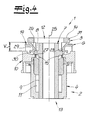
- Fig. 1 shows a quick coupling 1 according to the invention for producing a separable connection in a fluid line of a motor vehicle.
- the quick coupling 1 has a coupling body 2, which coupling body 2 is formed by a head part 3 and a sealing part 4.
- To the head part 3 is designed as a ring body 5 trained holder 6 which secures a tubular male part 7 in the coupling body 2.
- the insertion part 7 has a radial compression 8, which projects beyond a sealing surface 9 of the insertion part 7.
- the quick coupling 1 according to Fig. 1 via a securing element 10, according to Fig. 1 is arranged in a securing position and indicates in this way that the male member 7 is properly fixed by the holder 6 in the head part 3 and in the coupling body 2 of the quick coupling 1.
- the coupling body 2 has a through-bore 11, which extends from an inlet opening 12 to an outlet opening 13 in the coupling body 2.
- the inlet opening 12 is according to Fig. 1 arranged in an end face 14 of the head part 3, while the outlet opening 13 is arranged in a rear end face of the sealing part 4.
- a seal assembly 16 is arranged, which seal assembly 16 is formed of two O-ring seals 17 and disposed between the O-ring seals 17 intermediate member 18. According to Fig. 1 the seal assembly 16 seals the coupling body 2 against the sealing surface 9 of the male part 7.
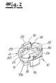
- Fig. 2 the holder 6 and the securing element 10 of the quick coupling 1 are shown.
- the holder 6 has two holding elements 19 and two handle plates 20.
- the two holding elements 19 and the two handle plates 20 are each arranged diametrically on the ring body 5 of the holder 6.
- the holding elements 19 each have a locking surface 21, with which locking surface 21 of the holder 6 at an input opening-side end face 22 of the compression 8 in the mounted state according to Fig. 1 is applied.
- the holding elements 19 each have a contact surface 23, which contact surface 23 is curved according to the embodiment and has the same curvature as the plug-in part 7 or the sealing surface 9. In the assembled state, the contact surfaces 23 bear against the sealing surface 9 of the insertion part 7.
- the holding elements 19 each have an oblique insertion surface 24, which insertion surfaces 24, starting from an inlet opening side end of the insertion 24 toward an exit opening side end of the insertion 24 obliquely toward a central axis or longitudinal axis 25 of the through hole 11 and in the direction of the outlet opening 13 are oriented.
- the securing element 10 has two diametrically disposed on an annular body 10a of the securing element 10 and formed as coupling projections 15 coupling elements.
- the coupling projections 15 pass through according to Fig. 2 in each case one introduced into the holding elements 19 coupling opening 26, so that the coupling projections 15 extend through the holding elements 19 in the through hole 11 of the coupling body 2.
- Portions of the coupling projections 15 extending into the through-hole 11 have inclined pressing surfaces 27.
- the pressing surfaces 27 extend obliquely from their inlet-side-side ends to their outlet-side-side ends in the direction of the central axis 25 and the outlet opening 13 of the through-hole 11.
- Supplementary is in Fig. 2 shown that the securing element has flat locking elements 34 which abut the coupling body side or through hole side on the handle plates 20.
- Fig. 2 it can be seen that the annular body 5 of the holder 6 is formed oval.
- the holder 6 is deformed with the proviso that starting from the in Fig. 1 shown, mounted state, a distance between the contact surfaces 23 is increased.
- the distance between the two contact surfaces 23 of the holding elements 19 can be increased in such a way that the insertion part 7 or the compression 8 of the insertion part 7 moves past the holding elements 19 in the direction of the inlet opening 12 of the coupling body 2, thus removing the insertion part 7 from the coupling body 2 can.
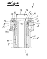
- Fig. 3 It is shown that the plug-in part 7 is inserted into the coupling body 2 with the holder 6 and the securing element 10 designed as an annular body 14 such that the plug-in part 7 is movably guided in the axial direction with respect to the central axis 25.
- the oblique pressing surfaces 27 of the coupling projections 15 of the securing element protrude through the coupling openings 26 of the connected to the annular body 5 of the holder 6 holding elements 19 in the through holes 11 of the coupling body 2.
- the securing element 10 is in a free position, in which free position the coupling projections 15 extend through the coupling openings 26 into the through hole 11.
- securing element 10 is displaceably guided exclusively in the axial direction with respect to the central axis 25 on the coupling body 2 and the head part 3 of the quick coupling 1.
- the holding elements 19 each have a rear opening 28, from which rear opening 28 of a coupling element recording 29 extends in the direction of the contact surface 23 of the retaining element 19.
- securing element 10 is shown in the securing position, in which securing position the securing element 10 is displaced in the direction of the inlet opening 12 of the coupling body 2 or head part 3.
- the securing position and free position of the securing element 10 represent end positions of the axial displacement, wherein the securing position represent the input opening-side end of the axial displacement path V and the free position, the output opening-side end of the axial displacement path V.
- Fig. 1 to 7 It is shown that the securing element 10 only from the free position according to the Fig. 3 in the securing position according to Fig. 7 is displaced when the male member 7 is completely inserted into the coupling body 2, wherein the compression 8 is held by the holding elements 19 of the holder 6 in the coupling body 2.
- the displacement of the securing element 10 from the free position according to the Fig. 3 in the securing position according to Fig. 1 and 7 allows easy detection of the properly established connection between the male part 7 and the coupling body 2
- Fig. 3 and 7 is also shown that the securing element 10 in both the free position according to Fig. 3 as well as in the hedging position according to Fig. 7 is locked with the holder 6.
- Fig. 7 is further shown that when a pressure is applied to the fluid system, not shown, the male member 7 is pressed in the direction of the input port 12.
- the compression 8 of the insertion part 7 acts on the holding elements 19 of the holder, as a result of which the holder is pressed against a collar 31 of the head part 3, in which collar 31 the input opening 12 is arranged.
- the holding elements 19 each have a locking projection 32, wherein the locking projections 32 abut a through-bore side annular surface 33 of the head part 3 and the collar 31. In this way it is ensured that an unintentional deformation of an aggregate formed by the holder 6 and the securing element 10 is prevented, which would mean an unintentional release of the insertion part 7.
- FIG. 12 is a further embodiment of a quick coupling 1 'according to the invention shown. It will be in the Fig. 1 to 7 and 8 to 12 identical reference numerals used for identical components or parts of the quick coupling 1 and the quick coupling 1 '.
- the holder (retainer) 6 has lifting arms 35 which are diametrically opposed to the holder 6 and flank the through hole 11.
- the two in the 8 to 12 shown lifting arms 35 is associated with a respective coupling projection 15 of the securing element 10, wherein the coupling projections 15 in the in Fig. 8 shown free position of the securing element 10 abut the lifting arms 35 of the holder 6.
- Fig. 1 the holder 6 has lifting arms 35 which are diametrically opposed to the holder 6 and flank the through hole 11.
- the two in the 8 to 12 shown lifting arms 35 is associated with a respective coupling projection 15 of the securing element 10, wherein the coupling projections 15 in the in Fig. 8 shown free position of the securing element 10 a
- the plug-in part 7 is according to Fig. 8 only in the through hole 11th introduced that the radial compression 8 of the plug 7 insertion surfaces 24 of the retainer 6 is not yet applied. If the plug-in part 7 is pushed into the coupling body 2 in the insertion direction or from the inlet opening 12 in the direction of the outlet opening 13 along the longitudinal axis 25 of the through-bore 11, then the compression 8 is brought into contact with the insertion surfaces 24 of the retainer 6. As a result, the retainer 6 is widened, resulting in Fig. 9 is pictured.
- Fig. 11 is the transition position or displacing position of the securing element 10, in which displacement position the lifting arms 35 by the compression 8, the coupling projections (coupling elements) 15 of the securing element 10 apart such that the coupling projections 15 can slide past the locking surfaces 21 of the holder 6.
- the securing element 10 is based on the in Fig. 11 shown displacement position in the in the Fig.
- the resiliently mounted on the holder 6 lifting arms 35 a lower restoring force than the resiliently connected to the retainer 6 holding elements 19.
- the holding elements 19 of the retainer 6 on the plug-in part or preferably and according to FIG Fig. 11 abut the cylindrical sealing surface 9 of the male part 7.
Landscapes
- Engineering & Computer Science (AREA)
- General Engineering & Computer Science (AREA)
- Mechanical Engineering (AREA)
- Quick-Acting Or Multi-Walled Pipe Joints (AREA)
Priority Applications (8)
| Application Number | Priority Date | Filing Date | Title |
|---|---|---|---|
| EP21156680.7A EP3839317B1 (fr) | 2013-01-15 | 2013-11-08 | Raccord rapide |
| PL19187825T PL3591277T3 (pl) | 2013-01-15 | 2013-11-08 | Szybkozłącze |
| EP19187825.5A EP3591277B1 (fr) | 2013-01-15 | 2013-11-08 | Raccord rapide |
| EP18172466.7A EP3399220B1 (fr) | 2013-01-15 | 2013-11-08 | Raccord rapide |
| US14/155,099 US9890887B2 (en) | 2013-01-15 | 2014-01-14 | Quick connector |
| JP2014004039A JP6506500B2 (ja) | 2013-01-15 | 2014-01-14 | クイックカプラ |
| KR1020140004482A KR102093521B1 (ko) | 2013-01-15 | 2014-01-14 | 퀵 커넥터 |
| CN201410017435.7A CN103925438B (zh) | 2013-01-15 | 2014-01-15 | 快速连接器 |
Applications Claiming Priority (2)
| Application Number | Priority Date | Filing Date | Title |
|---|---|---|---|
| US201361752787P | 2013-01-15 | 2013-01-15 | |
| US201361760864P | 2013-02-05 | 2013-02-05 |
Related Child Applications (5)
| Application Number | Title | Priority Date | Filing Date |
|---|---|---|---|
| EP21156680.7A Division EP3839317B1 (fr) | 2013-01-15 | 2013-11-08 | Raccord rapide |
| EP18172466.7A Division EP3399220B1 (fr) | 2013-01-15 | 2013-11-08 | Raccord rapide |
| EP18172466.7A Division-Into EP3399220B1 (fr) | 2013-01-15 | 2013-11-08 | Raccord rapide |
| EP19187825.5A Division EP3591277B1 (fr) | 2013-01-15 | 2013-11-08 | Raccord rapide |
| EP19187825.5A Division-Into EP3591277B1 (fr) | 2013-01-15 | 2013-11-08 | Raccord rapide |
Publications (3)
| Publication Number | Publication Date |
|---|---|
| EP2754941A2 true EP2754941A2 (fr) | 2014-07-16 |
| EP2754941A3 EP2754941A3 (fr) | 2016-10-12 |
| EP2754941B1 EP2754941B1 (fr) | 2019-09-04 |
Family
ID=49554091
Family Applications (4)
| Application Number | Title | Priority Date | Filing Date |
|---|---|---|---|
| EP13192083.7A Active EP2754941B1 (fr) | 2013-01-15 | 2013-11-08 | Raccord rapide |
| EP19187825.5A Active EP3591277B1 (fr) | 2013-01-15 | 2013-11-08 | Raccord rapide |
| EP21156680.7A Active EP3839317B1 (fr) | 2013-01-15 | 2013-11-08 | Raccord rapide |
| EP18172466.7A Active EP3399220B1 (fr) | 2013-01-15 | 2013-11-08 | Raccord rapide |
Family Applications After (3)
| Application Number | Title | Priority Date | Filing Date |
|---|---|---|---|
| EP19187825.5A Active EP3591277B1 (fr) | 2013-01-15 | 2013-11-08 | Raccord rapide |
| EP21156680.7A Active EP3839317B1 (fr) | 2013-01-15 | 2013-11-08 | Raccord rapide |
| EP18172466.7A Active EP3399220B1 (fr) | 2013-01-15 | 2013-11-08 | Raccord rapide |
Country Status (7)
| Country | Link |
|---|---|
| US (1) | US9890887B2 (fr) |
| EP (4) | EP2754941B1 (fr) |
| JP (1) | JP6506500B2 (fr) |
| KR (1) | KR102093521B1 (fr) |
| CN (1) | CN103925438B (fr) |
| DE (1) | DE202013012885U1 (fr) |
| PL (1) | PL3591277T3 (fr) |
Cited By (4)
| Publication number | Priority date | Publication date | Assignee | Title |
|---|---|---|---|---|
| KR20190093112A (ko) * | 2018-01-31 | 2019-08-08 | 아 레이몽 에 씨 | 듀얼-래치 퀵커넥터 |
| WO2020035506A1 (fr) * | 2018-08-14 | 2020-02-20 | Wema System As | Adaptateur de ligne et ensemble de ligne |
| US10981621B2 (en) | 2017-07-10 | 2021-04-20 | Gustav Magenwirth Gmbh & Co. Kg | Hydraulic line connection for a hydraulic brake for handlebar steering and handlebar with hydraulic brake |
| EP4060217A1 (fr) * | 2021-03-18 | 2022-09-21 | Hanil Tube Corporation | Connecteur rapide avec dispositif de retenue et de vérification |
Families Citing this family (28)
| Publication number | Priority date | Publication date | Assignee | Title |
|---|---|---|---|---|
| US10094499B2 (en) * | 2013-10-03 | 2018-10-09 | Nobel Plastiques | Quick-connect clip-on connector |
| US9151424B2 (en) * | 2013-10-24 | 2015-10-06 | Caterpillar Inc. | Connector for connecting hose coupler to drain knob |
| DE102014107655B4 (de) * | 2014-05-30 | 2024-07-11 | Voss Automotive Gmbh | Steckverbinder für Fluidleitungen mit innenliegender Adapterhülse |
| US10648601B2 (en) | 2014-06-10 | 2020-05-12 | Kohler Co. | Quick connect system for a fluid coupling |
| EP3174593B1 (fr) * | 2014-07-29 | 2019-09-18 | Colder Products Company | Dispositif de raccord axiale rapide d'un tube avec partie femelle et mâle et bouton déconnecteur perpendiculaire |
| KR101719973B1 (ko) * | 2015-07-14 | 2017-03-27 | 주식회사 우진 | 자동으로 체결 및 분리가능한 퀵 커플러 장치 |
| FR3044382B1 (fr) * | 2015-11-30 | 2017-12-08 | A Raymond Et Cie | Raccord tubulaire rapide avec bague secable pour connexion fluidique securisee |
| KR101714313B1 (ko) * | 2016-04-18 | 2017-03-22 | 주식회사 니프코코리아 | 자동차 유체통로용 퀵 커넥터 |
| CN105782614B (zh) * | 2016-04-28 | 2018-03-06 | 苏州富强科技有限公司 | 插拔式的密封快速接头 |
| US10502353B2 (en) | 2016-05-27 | 2019-12-10 | Kohler Co. | Quick connect release system for a fluid coupling |
| US10415733B2 (en) * | 2016-08-17 | 2019-09-17 | Cooper-Standard Automotive Inc. | Quick connector |
| JP6644992B2 (ja) * | 2016-10-28 | 2020-02-12 | 株式会社パイオラックス | クイックコネクター |
| US10816121B2 (en) | 2017-05-09 | 2020-10-27 | Martinrea International US Inc. | Quick connect coupling with verifier |
| DE102017208643B4 (de) * | 2017-05-22 | 2021-03-04 | Aft Automotive Gmbh | Kupplungselement zum Verbinden einer ersten fluidführenden Leitung mit einer zweiten fluidführenden Leitung sowie Kupplungsanordnung |
| EP3413405B1 (fr) * | 2017-06-08 | 2019-03-13 | Rosenberger Hochfrequenztechnik GmbH & Co. KG | Connecteur |
| DE102018107507A1 (de) * | 2018-03-28 | 2019-10-02 | Voss Automotive Gmbh | "Anschlussvorrichtung für Medienleitungen" |
| CN108317320A (zh) * | 2018-04-04 | 2018-07-24 | 辽宁壮龙无人机科技有限公司 | 接头组件及燃油供给管路 |
| JP6953472B2 (ja) * | 2019-04-26 | 2021-10-27 | Ckd株式会社 | マニホールド |
| EP3736481B1 (fr) * | 2019-05-07 | 2022-01-19 | A. Raymond et Cie | Ensemble connecteur rapide avec languette de vérification |
| FR3098888B1 (fr) * | 2019-07-15 | 2023-01-06 | A Raymond Et Cie | DISPOSITIF DE RACCORDEMENT fluidique COMPACT ET DEMONTABLE |
| US11796099B2 (en) * | 2019-08-22 | 2023-10-24 | Cooper-Standard Automotive Inc. | Connector having a pilot with an indicator |
| CN114555999B (zh) * | 2019-10-10 | 2024-09-10 | 欧梯克瑞士公司 | 由塑料制成的快速连接器 |
| DE102020204825A1 (de) * | 2020-04-16 | 2021-10-21 | Fränkische Industrial Pipes GmbH & Co. KG | Verbindungseinheit zur Verbindung von Fluidleitungen |
| US11852270B2 (en) | 2021-07-30 | 2023-12-26 | Raytheon Company | Compact, blind-mate fluid fitting |
| DE102021132818A1 (de) | 2021-12-13 | 2023-06-15 | Odelo Gmbh | Fahrzeugleuchte mit ESD Schutz |
| DE102022212634A1 (de) | 2022-11-25 | 2024-05-29 | Webasto SE | Verdrehsicherung für einen Quick-Konnektor, Stutzenanordnung und Quick-Konnektor mit Verdrehsicherung sowie Verfahren zur Montage desselben |
| DE102023133265A1 (de) | 2022-12-06 | 2024-06-06 | Illinois Tool Works Inc. | Detektionsvorrichtung sowie Verfahren zum Detektieren eines Kopplungszustandes einer Verbindungsvorrichtung |
| US12584574B2 (en) | 2023-02-02 | 2026-03-24 | Martinrea International US Inc. | Coolant quick connector with graphene, integrated latch and integrated O-ring retainer |
Family Cites Families (37)
| Publication number | Priority date | Publication date | Assignee | Title |
|---|---|---|---|---|
| US3873062A (en) * | 1973-11-30 | 1975-03-25 | Jerry Lynn Johnson | Air hose quick coupler |
| JPH0724716Y2 (ja) * | 1989-03-31 | 1995-06-05 | マルヤス工業株式会社 | 配管用継手 |
| US5211427A (en) | 1990-12-22 | 1993-05-18 | Usui Kokusai Sangyo Kaisha Ltd. | Piping connector |
| US5178424A (en) * | 1991-07-01 | 1993-01-12 | Itt Corporation | Pop-off quick connect indicator |
| US5303963A (en) * | 1992-03-27 | 1994-04-19 | Bundy Corporation | Tube coupling with secondary retainer clip |
| FR2715454B1 (fr) * | 1994-01-26 | 1996-04-12 | Caillau Ets | Connexion rapide. |
| US5499848A (en) * | 1994-09-26 | 1996-03-19 | Bundy Corporation | Connection verifier for a quick connector coupling |
| US5568946A (en) | 1994-12-14 | 1996-10-29 | Itt Corporation | Squeeze-to-release quick connector with snap-in retainer |
| JP3113170B2 (ja) | 1994-12-28 | 2000-11-27 | 株式会社東郷製作所 | コネクタ |
| FR2729454A1 (fr) * | 1995-01-16 | 1996-07-19 | Staubli Sa Ets | Raccord rapide de securite pour la jonction amovible de canalisations |
| US5628531A (en) * | 1995-04-26 | 1997-05-13 | Bundy Corporation | Quick connector with secondary latch |
| DE19515849B4 (de) * | 1995-04-29 | 2006-07-06 | Voss Automotive Gmbh | Steckkupplung für Druckmittel-Leitungen |
| JPH08312864A (ja) * | 1995-05-23 | 1996-11-26 | Maruyasu Kogyo Kk | 配管用継手 |
| US6007107A (en) | 1996-07-12 | 1999-12-28 | Container Technology, Inc. | Fluid coupling for matching delivery and supply lines irrespective of the relative rotational positions of the coupling members |
| US5873610A (en) * | 1996-12-19 | 1999-02-23 | Itt Automotive, Inc. | Female connector member for large tolerance male member endforms |
| US6155612A (en) | 1997-11-17 | 2000-12-05 | Itt Manufacturing Enterprises, Inc. | Hybrid quick connector |
| JP3321061B2 (ja) | 1997-12-19 | 2002-09-03 | 株式会社東郷製作所 | コネクタ |
| DE19822574C1 (de) * | 1998-05-20 | 1999-10-14 | Raymond A & Cie | Lösbare Schnellkupplung mit automatischer Montageanzeige |
| DE10024303B4 (de) | 2000-05-17 | 2005-09-08 | Rasmussen Gmbh | Aufnahme-Kupplungsvorrichtung einer Steckkupplung und Steckkupplung mit der Aufnahme-Kupplungsvorrichtung |
| DE10126205C1 (de) * | 2001-05-30 | 2002-04-04 | Raymond A & Cie | Lösbare Steckkupplung mit Schutzhülse |
| JP4055004B2 (ja) * | 2002-09-30 | 2008-03-05 | 東海ゴム工業株式会社 | コネクタ用回り止め具 |
| JP4264937B2 (ja) * | 2003-07-09 | 2009-05-20 | Smc株式会社 | チャック及び管継手 |
| DE502004008357D1 (de) | 2004-11-08 | 2008-12-11 | Kulm Holding Ag | Schnellkupplung |
| JP2006194432A (ja) * | 2004-12-17 | 2006-07-27 | Tokai Rubber Ind Ltd | 燃料輸送用の配管部材 |
| JP2006313010A (ja) * | 2005-04-04 | 2006-11-16 | Denso Corp | 配管継手装置 |
| ES2349016T3 (es) | 2005-05-03 | 2010-12-21 | Ti Group Automotive Systems, L.L.C. | Conectador rapido. |
| US7497480B2 (en) * | 2006-04-07 | 2009-03-03 | Ti Group Automotive Systems, Llc | Hybrid quick connector |
| FR2900456B1 (fr) * | 2006-04-28 | 2008-06-27 | Legris Sa | Raccord a double verrouillage |
| US7900972B2 (en) * | 2007-03-29 | 2011-03-08 | King Yuan Wang | Fluid connector for garden use |
| FR2921998B1 (fr) * | 2007-10-08 | 2012-03-16 | Staubli Sa Ets | Element femelle de raccord et raccord comprenant un tel element femelle |
| US7757704B2 (en) * | 2007-12-26 | 2010-07-20 | Taiwan Vertex Production Corp. | Coupling assembly with a core unit therein |
| DE102008013565B4 (de) * | 2008-03-11 | 2025-12-04 | A. Kayser Automotive Systems Gmbh | Einsteckkupplung |
| DE102009033943A1 (de) * | 2009-07-14 | 2011-01-20 | Aft Inh. Dirk Kramer E.K. | Steckkupplung |
| DE102011005220A1 (de) * | 2011-03-08 | 2012-09-13 | Fränkische Industrial Pipes GmbH & Co. KG | Verbindungsanordnung |
| US8366154B2 (en) * | 2011-06-15 | 2013-02-05 | Wang Cheng-An | Water pipe connector |
| DE102012106925A1 (de) * | 2012-07-30 | 2014-06-12 | Contitech Schlauch Gmbh | Schnellverbindungsanordnung zur lösbaren Verbindung einer Medienleitung mit einem Stutzen |
| EP2728236B1 (fr) | 2012-11-05 | 2017-04-19 | TI Automotive (Fuldabrück) GmbH | Accouplement rapide |
-
2013
- 2013-11-08 DE DE202013012885.2U patent/DE202013012885U1/de not_active Expired - Lifetime
- 2013-11-08 EP EP13192083.7A patent/EP2754941B1/fr active Active
- 2013-11-08 EP EP19187825.5A patent/EP3591277B1/fr active Active
- 2013-11-08 EP EP21156680.7A patent/EP3839317B1/fr active Active
- 2013-11-08 EP EP18172466.7A patent/EP3399220B1/fr active Active
- 2013-11-08 PL PL19187825T patent/PL3591277T3/pl unknown
-
2014
- 2014-01-14 JP JP2014004039A patent/JP6506500B2/ja active Active
- 2014-01-14 KR KR1020140004482A patent/KR102093521B1/ko active Active
- 2014-01-14 US US14/155,099 patent/US9890887B2/en not_active Expired - Fee Related
- 2014-01-15 CN CN201410017435.7A patent/CN103925438B/zh active Active
Cited By (9)
| Publication number | Priority date | Publication date | Assignee | Title |
|---|---|---|---|---|
| US10981621B2 (en) | 2017-07-10 | 2021-04-20 | Gustav Magenwirth Gmbh & Co. Kg | Hydraulic line connection for a hydraulic brake for handlebar steering and handlebar with hydraulic brake |
| KR20190093112A (ko) * | 2018-01-31 | 2019-08-08 | 아 레이몽 에 씨 | 듀얼-래치 퀵커넥터 |
| EP3521676A3 (fr) * | 2018-01-31 | 2019-08-14 | A. Raymond et Cie | Connecteur rapide à double verrouillage |
| US11199281B2 (en) | 2018-01-31 | 2021-12-14 | A. Raymond Et Cie. | Dual-latch quick connector |
| WO2020035506A1 (fr) * | 2018-08-14 | 2020-02-20 | Wema System As | Adaptateur de ligne et ensemble de ligne |
| EP4060217A1 (fr) * | 2021-03-18 | 2022-09-21 | Hanil Tube Corporation | Connecteur rapide avec dispositif de retenue et de vérification |
| CN115111446A (zh) * | 2021-03-18 | 2022-09-27 | 韩一Tube株式会社 | 具有保持器和验证器的快速连接器 |
| US11920715B2 (en) | 2021-03-18 | 2024-03-05 | Hanil Tube Corporation | Quick connector with retainer and verifier |
| CN115111446B (zh) * | 2021-03-18 | 2024-08-02 | 韩一Tube株式会社 | 具有保持器和验证器的快速连接器 |
Also Published As
| Publication number | Publication date |
|---|---|
| EP3399220A1 (fr) | 2018-11-07 |
| EP3591277A1 (fr) | 2020-01-08 |
| EP3839317A1 (fr) | 2021-06-23 |
| CN103925438B (zh) | 2017-01-04 |
| EP3839317B1 (fr) | 2024-05-22 |
| KR20140092260A (ko) | 2014-07-23 |
| CN103925438A (zh) | 2014-07-16 |
| EP2754941B1 (fr) | 2019-09-04 |
| PL3591277T3 (pl) | 2021-10-25 |
| KR102093521B1 (ko) | 2020-03-26 |
| EP3591277B1 (fr) | 2021-02-17 |
| EP3399220B1 (fr) | 2019-05-15 |
| US9890887B2 (en) | 2018-02-13 |
| EP2754941A3 (fr) | 2016-10-12 |
| JP2014137141A (ja) | 2014-07-28 |
| DE202013012885U1 (de) | 2021-02-18 |
| US20140197629A1 (en) | 2014-07-17 |
| JP6506500B2 (ja) | 2019-04-24 |
| EP3839317C0 (fr) | 2024-05-22 |
Similar Documents
| Publication | Publication Date | Title |
|---|---|---|
| EP2754941B1 (fr) | Raccord rapide | |
| EP2728236B1 (fr) | Accouplement rapide | |
| EP2880349B1 (fr) | Dispositif de raccordement rapide pour le raccordement libérable d'une conduite de fluide à une rallonge | |
| DE69520669T2 (de) | Tiefziehbare schnellkupplung | |
| DE3310385C2 (fr) | ||
| DE3235464C2 (fr) | ||
| DE69715659T2 (de) | Schnellkupplung mit abbrechbaren schnappverriegelungshalter | |
| EP1805447B1 (fr) | Raccord enfichable resistant a la traction | |
| DE69327006T2 (de) | Schnellkupplung für hochdruck | |
| EP1701082B1 (fr) | Portion d'extrémité de conduite à élément d'enfichage surmoulé | |
| DE69500213T2 (de) | Schnellverbindung | |
| WO2014136014A1 (fr) | Raccord à emboîtement pour deux tubes et procédé de montage du raccord à emboîtement | |
| DE69400499T2 (de) | Vorrichtung zum dichten Verbinden eines Schlauches mit einem starren Rohrende | |
| DE102014107530A1 (de) | "Aufnahmeteil für eine Fluid-Steckkupplung und Fluid-Steckkupplung mit einem derartigen Aufnahmeteil" | |
| DE69521428T2 (de) | Rohrverbindung für aussergewöhnliche gebrauchsbedingungen | |
| DE3705610A1 (de) | Loesbare steckverbindung fuer rohrleitungen | |
| DE69612909T2 (de) | Fluiddichtkupplung | |
| EP2568207B1 (fr) | Raccordement de tuyau | |
| EP2505899B1 (fr) | Raccordement rapide pour conduits sous pression hydraulique | |
| EP3763985B1 (fr) | Système d'accouplement pour tuyauteries et / ou conduites ainsi que procédé de fabrication et d'arrêt d'un écoulement de fluide | |
| EP3421075B1 (fr) | Dispositif de liaison fluidique médical | |
| DE102008058675B4 (de) | Steckverbindung | |
| WO2018210622A1 (fr) | Dispositif de raccordement | |
| EP4232735B1 (fr) | Unité de connexion de fluide | |
| EP3090909B1 (fr) | Fiche de raccordement fluidique |
Legal Events
| Date | Code | Title | Description |
|---|---|---|---|
| PUAI | Public reference made under article 153(3) epc to a published international application that has entered the european phase |
Free format text: ORIGINAL CODE: 0009012 |
|
| 17P | Request for examination filed |
Effective date: 20131108 |
|
| AK | Designated contracting states |
Kind code of ref document: A2 Designated state(s): AL AT BE BG CH CY CZ DE DK EE ES FI FR GB GR HR HU IE IS IT LI LT LU LV MC MK MT NL NO PL PT RO RS SE SI SK SM TR |
|
| AX | Request for extension of the european patent |
Extension state: BA ME |
|
| PUAL | Search report despatched |
Free format text: ORIGINAL CODE: 0009013 |
|
| AK | Designated contracting states |
Kind code of ref document: A3 Designated state(s): AL AT BE BG CH CY CZ DE DK EE ES FI FR GB GR HR HU IE IS IT LI LT LU LV MC MK MT NL NO PL PT RO RS SE SI SK SM TR |
|
| AX | Request for extension of the european patent |
Extension state: BA ME |
|
| RIC1 | Information provided on ipc code assigned before grant |
Ipc: F16L 37/138 20060101ALI20160906BHEP Ipc: F16L 37/084 20060101ALI20160906BHEP Ipc: F16L 37/098 20060101AFI20160906BHEP |
|
| STAA | Information on the status of an ep patent application or granted ep patent |
Free format text: STATUS: REQUEST FOR EXAMINATION WAS MADE |
|
| R17P | Request for examination filed (corrected) |
Effective date: 20170223 |
|
| RBV | Designated contracting states (corrected) |
Designated state(s): AL AT BE BG CH CY CZ DE DK EE ES FI FR GB GR HR HU IE IS IT LI LT LU LV MC MK MT NL NO PL PT RO RS SE SI SK SM TR |
|
| STAA | Information on the status of an ep patent application or granted ep patent |
Free format text: STATUS: EXAMINATION IS IN PROGRESS |
|
| 17Q | First examination report despatched |
Effective date: 20180201 |
|
| GRAP | Despatch of communication of intention to grant a patent |
Free format text: ORIGINAL CODE: EPIDOSNIGR1 |
|
| STAA | Information on the status of an ep patent application or granted ep patent |
Free format text: STATUS: GRANT OF PATENT IS INTENDED |
|
| INTG | Intention to grant announced |
Effective date: 20190329 |
|
| RIN1 | Information on inventor provided before grant (corrected) |
Inventor name: PEPE, RICHARD M. Inventor name: BOL, ALEXANDER Inventor name: BUBE, KAY Inventor name: CHOO, ALBERT (SEONG-HWA) Inventor name: JENSEN, HANS Inventor name: BARTHEL, IRIS |
|
| GRAS | Grant fee paid |
Free format text: ORIGINAL CODE: EPIDOSNIGR3 |
|
| GRAA | (expected) grant |
Free format text: ORIGINAL CODE: 0009210 |
|
| STAA | Information on the status of an ep patent application or granted ep patent |
Free format text: STATUS: THE PATENT HAS BEEN GRANTED |
|
| AK | Designated contracting states |
Kind code of ref document: B1 Designated state(s): AL AT BE BG CH CY CZ DE DK EE ES FI FR GB GR HR HU IE IS IT LI LT LU LV MC MK MT NL NO PL PT RO RS SE SI SK SM TR |
|
| REG | Reference to a national code |
Ref country code: GB Ref legal event code: FG4D Free format text: NOT ENGLISH |
|
| REG | Reference to a national code |
Ref country code: CH Ref legal event code: EP |
|
| REG | Reference to a national code |
Ref country code: AT Ref legal event code: REF Ref document number: 1175820 Country of ref document: AT Kind code of ref document: T Effective date: 20190915 |
|
| REG | Reference to a national code |
Ref country code: DE Ref legal event code: R096 Ref document number: 502013013501 Country of ref document: DE |
|
| REG | Reference to a national code |
Ref country code: IE Ref legal event code: FG4D Free format text: LANGUAGE OF EP DOCUMENT: GERMAN |
|
| REG | Reference to a national code |
Ref country code: NL Ref legal event code: MP Effective date: 20190904 |
|
| REG | Reference to a national code |
Ref country code: LT Ref legal event code: MG4D |
|
| PG25 | Lapsed in a contracting state [announced via postgrant information from national office to epo] |
Ref country code: BG Free format text: LAPSE BECAUSE OF FAILURE TO SUBMIT A TRANSLATION OF THE DESCRIPTION OR TO PAY THE FEE WITHIN THE PRESCRIBED TIME-LIMIT Effective date: 20191204 Ref country code: SE Free format text: LAPSE BECAUSE OF FAILURE TO SUBMIT A TRANSLATION OF THE DESCRIPTION OR TO PAY THE FEE WITHIN THE PRESCRIBED TIME-LIMIT Effective date: 20190904 Ref country code: NO Free format text: LAPSE BECAUSE OF FAILURE TO SUBMIT A TRANSLATION OF THE DESCRIPTION OR TO PAY THE FEE WITHIN THE PRESCRIBED TIME-LIMIT Effective date: 20191204 Ref country code: LT Free format text: LAPSE BECAUSE OF FAILURE TO SUBMIT A TRANSLATION OF THE DESCRIPTION OR TO PAY THE FEE WITHIN THE PRESCRIBED TIME-LIMIT Effective date: 20190904 Ref country code: FI Free format text: LAPSE BECAUSE OF FAILURE TO SUBMIT A TRANSLATION OF THE DESCRIPTION OR TO PAY THE FEE WITHIN THE PRESCRIBED TIME-LIMIT Effective date: 20190904 Ref country code: HR Free format text: LAPSE BECAUSE OF FAILURE TO SUBMIT A TRANSLATION OF THE DESCRIPTION OR TO PAY THE FEE WITHIN THE PRESCRIBED TIME-LIMIT Effective date: 20190904 |
|
| PG25 | Lapsed in a contracting state [announced via postgrant information from national office to epo] |
Ref country code: AL Free format text: LAPSE BECAUSE OF FAILURE TO SUBMIT A TRANSLATION OF THE DESCRIPTION OR TO PAY THE FEE WITHIN THE PRESCRIBED TIME-LIMIT Effective date: 20190904 Ref country code: LV Free format text: LAPSE BECAUSE OF FAILURE TO SUBMIT A TRANSLATION OF THE DESCRIPTION OR TO PAY THE FEE WITHIN THE PRESCRIBED TIME-LIMIT Effective date: 20190904 Ref country code: RS Free format text: LAPSE BECAUSE OF FAILURE TO SUBMIT A TRANSLATION OF THE DESCRIPTION OR TO PAY THE FEE WITHIN THE PRESCRIBED TIME-LIMIT Effective date: 20190904 Ref country code: GR Free format text: LAPSE BECAUSE OF FAILURE TO SUBMIT A TRANSLATION OF THE DESCRIPTION OR TO PAY THE FEE WITHIN THE PRESCRIBED TIME-LIMIT Effective date: 20191205 Ref country code: ES Free format text: LAPSE BECAUSE OF FAILURE TO SUBMIT A TRANSLATION OF THE DESCRIPTION OR TO PAY THE FEE WITHIN THE PRESCRIBED TIME-LIMIT Effective date: 20190904 |
|
| PG25 | Lapsed in a contracting state [announced via postgrant information from national office to epo] |
Ref country code: PT Free format text: LAPSE BECAUSE OF FAILURE TO SUBMIT A TRANSLATION OF THE DESCRIPTION OR TO PAY THE FEE WITHIN THE PRESCRIBED TIME-LIMIT Effective date: 20200106 Ref country code: EE Free format text: LAPSE BECAUSE OF FAILURE TO SUBMIT A TRANSLATION OF THE DESCRIPTION OR TO PAY THE FEE WITHIN THE PRESCRIBED TIME-LIMIT Effective date: 20190904 Ref country code: IT Free format text: LAPSE BECAUSE OF FAILURE TO SUBMIT A TRANSLATION OF THE DESCRIPTION OR TO PAY THE FEE WITHIN THE PRESCRIBED TIME-LIMIT Effective date: 20190904 Ref country code: PL Free format text: LAPSE BECAUSE OF FAILURE TO SUBMIT A TRANSLATION OF THE DESCRIPTION OR TO PAY THE FEE WITHIN THE PRESCRIBED TIME-LIMIT Effective date: 20190904 Ref country code: RO Free format text: LAPSE BECAUSE OF FAILURE TO SUBMIT A TRANSLATION OF THE DESCRIPTION OR TO PAY THE FEE WITHIN THE PRESCRIBED TIME-LIMIT Effective date: 20190904 Ref country code: NL Free format text: LAPSE BECAUSE OF FAILURE TO SUBMIT A TRANSLATION OF THE DESCRIPTION OR TO PAY THE FEE WITHIN THE PRESCRIBED TIME-LIMIT Effective date: 20190904 |
|
| PG25 | Lapsed in a contracting state [announced via postgrant information from national office to epo] |
Ref country code: CZ Free format text: LAPSE BECAUSE OF FAILURE TO SUBMIT A TRANSLATION OF THE DESCRIPTION OR TO PAY THE FEE WITHIN THE PRESCRIBED TIME-LIMIT Effective date: 20190904 Ref country code: SK Free format text: LAPSE BECAUSE OF FAILURE TO SUBMIT A TRANSLATION OF THE DESCRIPTION OR TO PAY THE FEE WITHIN THE PRESCRIBED TIME-LIMIT Effective date: 20190904 Ref country code: SM Free format text: LAPSE BECAUSE OF FAILURE TO SUBMIT A TRANSLATION OF THE DESCRIPTION OR TO PAY THE FEE WITHIN THE PRESCRIBED TIME-LIMIT Effective date: 20190904 Ref country code: IS Free format text: LAPSE BECAUSE OF FAILURE TO SUBMIT A TRANSLATION OF THE DESCRIPTION OR TO PAY THE FEE WITHIN THE PRESCRIBED TIME-LIMIT Effective date: 20200224 |
|
| REG | Reference to a national code |
Ref country code: DE Ref legal event code: R097 Ref document number: 502013013501 Country of ref document: DE |
|
| REG | Reference to a national code |
Ref country code: CH Ref legal event code: PL |
|
| PLBE | No opposition filed within time limit |
Free format text: ORIGINAL CODE: 0009261 |
|
| STAA | Information on the status of an ep patent application or granted ep patent |
Free format text: STATUS: NO OPPOSITION FILED WITHIN TIME LIMIT |
|
| PG2D | Information on lapse in contracting state deleted |
Ref country code: IS |
|
| PG25 | Lapsed in a contracting state [announced via postgrant information from national office to epo] |
Ref country code: CH Free format text: LAPSE BECAUSE OF NON-PAYMENT OF DUE FEES Effective date: 20191130 Ref country code: LI Free format text: LAPSE BECAUSE OF NON-PAYMENT OF DUE FEES Effective date: 20191130 Ref country code: LU Free format text: LAPSE BECAUSE OF NON-PAYMENT OF DUE FEES Effective date: 20191108 Ref country code: DK Free format text: LAPSE BECAUSE OF FAILURE TO SUBMIT A TRANSLATION OF THE DESCRIPTION OR TO PAY THE FEE WITHIN THE PRESCRIBED TIME-LIMIT Effective date: 20190904 Ref country code: MC Free format text: LAPSE BECAUSE OF FAILURE TO SUBMIT A TRANSLATION OF THE DESCRIPTION OR TO PAY THE FEE WITHIN THE PRESCRIBED TIME-LIMIT Effective date: 20190904 Ref country code: IS Free format text: LAPSE BECAUSE OF FAILURE TO SUBMIT A TRANSLATION OF THE DESCRIPTION OR TO PAY THE FEE WITHIN THE PRESCRIBED TIME-LIMIT Effective date: 20200105 |
|
| 26N | No opposition filed |
Effective date: 20200605 |
|
| REG | Reference to a national code |
Ref country code: BE Ref legal event code: MM Effective date: 20191130 |
|
| PG25 | Lapsed in a contracting state [announced via postgrant information from national office to epo] |
Ref country code: SI Free format text: LAPSE BECAUSE OF FAILURE TO SUBMIT A TRANSLATION OF THE DESCRIPTION OR TO PAY THE FEE WITHIN THE PRESCRIBED TIME-LIMIT Effective date: 20190904 |
|
| GBPC | Gb: european patent ceased through non-payment of renewal fee |
Effective date: 20191204 |
|
| PG25 | Lapsed in a contracting state [announced via postgrant information from national office to epo] |
Ref country code: IE Free format text: LAPSE BECAUSE OF NON-PAYMENT OF DUE FEES Effective date: 20191108 Ref country code: GB Free format text: LAPSE BECAUSE OF NON-PAYMENT OF DUE FEES Effective date: 20191204 |
|
| PG25 | Lapsed in a contracting state [announced via postgrant information from national office to epo] |
Ref country code: BE Free format text: LAPSE BECAUSE OF NON-PAYMENT OF DUE FEES Effective date: 20191130 |
|
| REG | Reference to a national code |
Ref country code: AT Ref legal event code: MM01 Ref document number: 1175820 Country of ref document: AT Kind code of ref document: T Effective date: 20191108 |
|
| PG25 | Lapsed in a contracting state [announced via postgrant information from national office to epo] |
Ref country code: AT Free format text: LAPSE BECAUSE OF NON-PAYMENT OF DUE FEES Effective date: 20191108 |
|
| PG25 | Lapsed in a contracting state [announced via postgrant information from national office to epo] |
Ref country code: CY Free format text: LAPSE BECAUSE OF FAILURE TO SUBMIT A TRANSLATION OF THE DESCRIPTION OR TO PAY THE FEE WITHIN THE PRESCRIBED TIME-LIMIT Effective date: 20190904 |
|
| PG25 | Lapsed in a contracting state [announced via postgrant information from national office to epo] |
Ref country code: MT Free format text: LAPSE BECAUSE OF FAILURE TO SUBMIT A TRANSLATION OF THE DESCRIPTION OR TO PAY THE FEE WITHIN THE PRESCRIBED TIME-LIMIT Effective date: 20190904 Ref country code: HU Free format text: LAPSE BECAUSE OF FAILURE TO SUBMIT A TRANSLATION OF THE DESCRIPTION OR TO PAY THE FEE WITHIN THE PRESCRIBED TIME-LIMIT; INVALID AB INITIO Effective date: 20131108 |
|
| PG25 | Lapsed in a contracting state [announced via postgrant information from national office to epo] |
Ref country code: TR Free format text: LAPSE BECAUSE OF FAILURE TO SUBMIT A TRANSLATION OF THE DESCRIPTION OR TO PAY THE FEE WITHIN THE PRESCRIBED TIME-LIMIT Effective date: 20190904 |
|
| PG25 | Lapsed in a contracting state [announced via postgrant information from national office to epo] |
Ref country code: MK Free format text: LAPSE BECAUSE OF FAILURE TO SUBMIT A TRANSLATION OF THE DESCRIPTION OR TO PAY THE FEE WITHIN THE PRESCRIBED TIME-LIMIT Effective date: 20190904 |
|
| P01 | Opt-out of the competence of the unified patent court (upc) registered |
Effective date: 20230524 |
|
| PGFP | Annual fee paid to national office [announced via postgrant information from national office to epo] |
Ref country code: DE Payment date: 20241119 Year of fee payment: 12 |
|
| PGFP | Annual fee paid to national office [announced via postgrant information from national office to epo] |
Ref country code: FR Payment date: 20241121 Year of fee payment: 12 |