EP2754997A2 - Système de mesure - Google Patents
Système de mesure Download PDFInfo
- Publication number
- EP2754997A2 EP2754997A2 EP14000111.6A EP14000111A EP2754997A2 EP 2754997 A2 EP2754997 A2 EP 2754997A2 EP 14000111 A EP14000111 A EP 14000111A EP 2754997 A2 EP2754997 A2 EP 2754997A2
- Authority
- EP
- European Patent Office
- Prior art keywords
- magnetic field
- field sensor
- field vector
- vector
- measuring system
- Prior art date
- Legal status (The legal status is an assumption and is not a legal conclusion. Google has not performed a legal analysis and makes no representation as to the accuracy of the status listed.)
- Granted
Links
Images

Classifications
-
- G—PHYSICS
- G01—MEASURING; TESTING
- G01R—MEASURING ELECTRIC VARIABLES; MEASURING MAGNETIC VARIABLES
- G01R33/00—Arrangements or instruments for measuring magnetic variables
- G01R33/02—Measuring direction or magnitude of magnetic fields or magnetic flux
- G01R33/06—Measuring direction or magnitude of magnetic fields or magnetic flux using galvano-magnetic devices
- G01R33/09—Magnetoresistive devices
-
- G—PHYSICS
- G01—MEASURING; TESTING
- G01D—MEASURING NOT SPECIALLY ADAPTED FOR A SPECIFIC VARIABLE; ARRANGEMENTS FOR MEASURING TWO OR MORE VARIABLES NOT COVERED IN A SINGLE OTHER SUBCLASS; TARIFF METERING APPARATUS; MEASURING OR TESTING NOT OTHERWISE PROVIDED FOR
- G01D5/00—Mechanical means for transferring the output of a sensing member; Means for converting the output of a sensing member to another variable where the form or nature of the sensing member does not constrain the means for converting; Transducers not specially adapted for a specific variable
- G01D5/12—Mechanical means for transferring the output of a sensing member; Means for converting the output of a sensing member to another variable where the form or nature of the sensing member does not constrain the means for converting; Transducers not specially adapted for a specific variable using electric or magnetic means
- G01D5/14—Mechanical means for transferring the output of a sensing member; Means for converting the output of a sensing member to another variable where the form or nature of the sensing member does not constrain the means for converting; Transducers not specially adapted for a specific variable using electric or magnetic means influencing the magnitude of a current or voltage
- G01D5/142—Mechanical means for transferring the output of a sensing member; Means for converting the output of a sensing member to another variable where the form or nature of the sensing member does not constrain the means for converting; Transducers not specially adapted for a specific variable using electric or magnetic means influencing the magnitude of a current or voltage using Hall-effect devices
- G01D5/145—Mechanical means for transferring the output of a sensing member; Means for converting the output of a sensing member to another variable where the form or nature of the sensing member does not constrain the means for converting; Transducers not specially adapted for a specific variable using electric or magnetic means influencing the magnitude of a current or voltage using Hall-effect devices influenced by the relative movement between the Hall device and magnetic fields
Definitions
- the present invention relates to a measuring system.
- an angle sensor and a method for determining an angle between a sensor arrangement and a magnetic field are known.
- the angle transmitter has a magnetic field generating, with respect to a rotational axis in different rotational positions relative to the sensor arrangement adjustable magnet.
- the sensor arrangement has a first magnetic field sensor for detecting a first magnetic field component oriented transverse to the rotational axis and a second magnetic field sensor for detecting a second magnetic field component, which is arranged transversely to a plane spanned by the rotational axis and the first magnetic field component.
- the sensor arrangement has a third magnetic field sensor for detecting a third magnetic field component oriented in the direction of the axis of rotation.
- a semiconductor chip and a method for generating pulse edges which are associated synchronously with the movement of a mechanical part, are known.
- a magnetic field is generated and at least two measurement signals are detected for the magnetic field.
- the magnetic field is varied in dependence on the movement of the mechanical part such that the measurement signals are modulated out of phase with each other.
- a first measurement signal is compared with a first reference value.
- a second measurement signal is compared with a second reference value.
- the magnitude of the first measurement signal is compared with the magnitude of the second measurement signal.
- a pulse edge is generated if at least one of these comparisons results in a match or the result of the comparison in question changes its sign.
- From the EP 1 111 392 A1 is a detection of the rotational speed and angular position of a rotating wheel with adjustable threshold for drift compensation known.
- the detection of the speed and the Angular position of a wheel by means of a non-contact wheel scanning sensor, which generates a pulse train.
- the amplitude of the pulses is compared in a comparator with a variable shadow threshold.
- the switching threshold is adjusted so that the amount of the difference between the amplitudes of the pulses and the switching threshold does not exceed a predefinable maximum value.
- the rotation angle sensor has a rotatable shaft, a magnet coupled to the rotatable shaft, and a magnetosensitive sensor element.
- the sensor element generates a sinusoidal and a cosinusoidal output signal as a function of the relative angle of rotation between the magnet and the sensor.
- the rotation angle sensor has an evaluation unit which generates a signal corresponding to the rotation angle from the output signals.
- the shaft is additionally slidably guided linearly parallel to its axis along a guide track during its rotation about its axis, so that the distance between magnet and sensor changes in accordance with a gradient of the guide track.
- the evaluation unit determines from output signals of the sensor element a signal from which the distance between the sensor element and the magnet and thus the number of full revolutions of the shaft can be determined. From the sinusoidal and cosinusoidal output signals, a fine signal is detected within one full revolution and this fine signal is added to the value of the full revolution multiplied by 360 °.
- a measuring system with a magnetic field sensor arrangement and with a transmitter and with an evaluation circuit is provided.
- the magnetic field sensor arrangement has a first magnetic field sensor integrated in a semiconductor chip for measuring a first component of a magnetic field vector in a first spatial direction and a second magnetic field sensor integrated in the semiconductor chip for measuring a second component of the magnetic field vector in a second spatial direction and a third magnetic field sensor integrated in the semiconductor chip for measuring a third magnetic field sensor Component of the magnetic field vector in a third spatial direction.
- the transmitter is designed to change the magnetic field vector in the first spatial direction and in the second spatial direction and in the third spatial direction as a function of its rotational and / or translatory movement.
- the magnetic field vector is defined at the location of the magnetic field sensors by measuring the components of the magnetic field vector. The change in the magnetic field vector caused by the movement of the sensor describes a closed and crossing-free line in all three spatial directions.
- the evaluation circuit of the first magnetic field sensor and the second magnetic field sensor and the third magnetic field sensor are connected.
- the evaluation circuit is set up to determine the position of the encoder based on a first measurement signal of the first magnetic field sensor and a second measurement signal of the second magnetic field sensor and a third measurement signal of the third magnetic field sensor.
- the line described by the magnetic field vector is at least partially helical.
- the transmitter is designed to modulate a length of the magnetic field vector as a function of the rotational and / or translatory movement. Such an amplitude modulation can take place for one or more components of the magnetic field vector in different spatial directions.
- the line described by the magnetic field vector has at least two intermeshing helical sections.
- the nested helical sections are spaced apart by different amplitudes of the magnetic field vector in at least two spatial directions.
- the encoder is designed to modulate a slope of a helical shape of the line of the magnetic field vector as a function of the rotational and / or translational movement of the encoder.
- the encoder is designed, in response to the rotational and / or translational movement, a first oscillation of the first component of the magnetic field vector at a first frequency and a second oscillation of the second component of the magnetic field vector at a second frequency modulate, wherein the first frequency and the second frequency are different.
- the encoder has a number of magnets and / or a number of coils for generating the magnetic field vector.
- the magnetic field sensor arrangement has a number of magnets and / or a number of coils for generating the magnetic field vector.
- the magnetic field vector is changed by magnetically conductive material of the encoder - for example by teeth of gears - by the movement of the encoder.
- a measuring system 1 is shown schematically.
- the measuring system 1 has a magnetic field sensor arrangement 10 and an encoder 20.
- To the magnetic field sensor assembly 10 is, as in Fig. 2 shown schematically an evaluation circuit 30 connected.
- a coordinate system with spatial directions x, y and z is shown schematically.
- the origin of the coordinate system is located in the center of the magnetic field sensor arrangement 10, in FIG Fig. 1 Plotted slightly offset for better visibility.
- a magnetic field vector B - here for the magnetic flux density - and its components B x , B y , B z in the spatial directions x, y, z are shown schematically.
- the magnetic field sensor arrangement 10 has a first magnetic field sensor 11 and a second magnetic field sensor 12 and a third magnetic field sensor 13.
- the magnetic field sensors 11, 12, 13 are integrated in a semiconductor chip.
- the magnetic field sensors 11, 12, 13 are in the embodiment of Fig. 1 Hall sensors.
- magnetic-resistant sensors or coils can be integrated as magnetic field sensors 11, 12, 13.
- the first magnetic field sensor 11 is designed to measure the first component B x of the magnetic field vector B in the first spatial direction x.
- the second magnetic field sensor 12 is designed to measure the second component B z of the magnetic field vector B in the second spatial direction z.
- the third magnetic field sensor 13 is designed to measure the third component B y of the magnetic field vector B in a third spatial direction y.
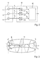
- FIG. 3 shows a representation of the magnetic vector B in three-dimensional space (spherical coordinates).
- the magnetic vector B is projected onto the XY plane, for example.
- the magnetic field is also modulated in the z-direction.
- the magnetic field vector B describes a helix.
- the encoder 20 is thus formed, depending on its rotational and / or translational movement to change the magnetic field vector B in the first spatial direction x and in the second spatial direction z and in the third spatial direction y.
- the length of the projection of the vector B remains constant on the XY plane, this leads to ambiguities at crossing points, since, for example, the way to go can not be distinguished from the return path in the crossing points. Therefore, in the embodiment of Fig. 2 together with the z-modulation, the amount of the x-component B x and the y-component B y of the magnetic field vector B modulated.
- the advantage is achieved that ambiguities are avoided by the embodiment of the Fig. 3 the change in the magnetic field vector B caused by the movement of the transmitter 20 describes a closed and crossing-free line in all three spatial directions x, y, z.
- Deviating from Fig. 3 encoders can be provided in which the magnetic field vector B passes through a plurality of spirals in different planes next to each other for a complete cycle. As soon as vector B has arrived outside or inside in an xy plane, it does not jump inward or outward in the same xy plane, but instead changes into the neighboring xy plane and spirals inward in the neighboring xy plane outside in the same direction of rotation. Arrived in the last xy plane, the vector B runs helically, on a cylinder, without crossing the previous vector trajectories, back to the beginning. On the other hand are in Fig. 3 to recognize two spirals which are pushed one inside the other and which also describe a closed and crossing-free line in all three spatial directions x, y, z. Deviating from Fig. 3 can also be used a larger number of telescoped spirals.
- FIG. 2 is a block diagram with an evaluation circuit 30 shown schematically.
- the first magnetic field sensor 11 and the second magnetic field sensor 12 and the third magnetic field sensor 13 of the magnetic field sensor arrangement 10 are connected to the evaluation circuit 30.
- Each magnetic field sensor 11, 12, 13 outputs an analog measuring signal V x , V y , V z , which is converted by one of the analog-to-digital converters 31, 32, 33 into a digital measuring signal S x , S y , S z .
- the evaluation circuit 30 has logic 35.
- the logic 35 is for example a processor.
- the evaluation circuit 30 is set up to determine the position of the encoder 30 based on the first measurement signal S x of the first magnetic field sensor 11 and the second measurement signal S z of the second magnetic field sensor 12 and the third measurement signal S y of the third magnetic field sensor 13.
- the determination of the position from the measurement signals S x , S y , S z can be done for example by means of an algorithm or by means of table and interpolation.
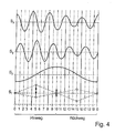
- Fig. 4 shows the signals S x , S y , S z , S r for outward and return path according to the Fig. 3 in a schematic diagram.
- S r S x 2 + S y 2 + S z 2
- the signal S r is the magnitude or length of the magnetic field vector B. As long as the way back and forth sufficiently strong, you have many variations. The two reversal points do not have to, as in Fig. 4 shown lying on the same shell. etc.
- the invention is not limited to the illustrated embodiments of the FIGS. 1 to 4 limited.
- the encoder 20 it is possible with the encoder 20 to generate another line course of a closed, crossing-free line in three-dimensional space.
- the functionality of the measuring system according to Fig. 1 can be used particularly advantageously for the measurement of positions and movements of adjustment systems.
Landscapes
- Physics & Mathematics (AREA)
- General Physics & Mathematics (AREA)
- Condensed Matter Physics & Semiconductors (AREA)
- Transmission And Conversion Of Sensor Element Output (AREA)
- Measuring Magnetic Variables (AREA)
Applications Claiming Priority (1)
| Application Number | Priority Date | Filing Date | Title |
|---|---|---|---|
| DE102013000432.2A DE102013000432A1 (de) | 2013-01-14 | 2013-01-14 | Messsystem |
Publications (3)
| Publication Number | Publication Date |
|---|---|
| EP2754997A2 true EP2754997A2 (fr) | 2014-07-16 |
| EP2754997A3 EP2754997A3 (fr) | 2014-10-29 |
| EP2754997B1 EP2754997B1 (fr) | 2016-09-21 |
Family
ID=49920131
Family Applications (1)
| Application Number | Title | Priority Date | Filing Date |
|---|---|---|---|
| EP14000111.6A Active EP2754997B1 (fr) | 2013-01-14 | 2014-01-13 | Système de mesure |
Country Status (3)
| Country | Link |
|---|---|
| US (1) | US9348003B2 (fr) |
| EP (1) | EP2754997B1 (fr) |
| DE (1) | DE102013000432A1 (fr) |
Families Citing this family (4)
| Publication number | Priority date | Publication date | Assignee | Title |
|---|---|---|---|---|
| DE102016113126A1 (de) | 2016-07-15 | 2018-01-18 | Tdk-Micronas Gmbh | Verfahren zur Berechnung der Phasenverschiebung oder Amplitude eines Drei-Phasen-Systems |
| DE102017109531B3 (de) | 2017-05-04 | 2018-07-19 | Schaeffler Technologies AG & Co. KG | Sensoranordnung und Verfahren zum Erzeugen einer Positionswechselsignalfolge |
| CN109084671B (zh) * | 2018-08-01 | 2024-06-04 | 中国煤炭科工集团太原研究院有限公司 | 一种煤矿履带式行走装备行程测量系统 |
| CN118310570A (zh) * | 2024-05-17 | 2024-07-09 | 无锡埃斯特磁科技有限公司 | 用于磁性编码器中磁模块的运行状态的检测方法及系统 |
Citations (4)
| Publication number | Priority date | Publication date | Assignee | Title |
|---|---|---|---|---|
| EP1111392A1 (fr) | 1999-12-20 | 2001-06-27 | Micronas GmbH | Mesure du nombre de tours et position angulaire d'une roue en rotation avec seuil de couplage adapté pour compensation de dérive |
| EP1503182B1 (fr) | 2003-07-29 | 2008-12-17 | Tech3 e.K. | Capteur magnétique d'angle de rotation |
| DE102008059401A1 (de) | 2008-11-27 | 2010-06-10 | Micronas Gmbh | Halbleiterchip und Verfahren zum Erzeugen von Impulsflanken, die der Bewegung eines mechanischen Teiles synchron zugeordnet sind |
| EP2354769A1 (fr) | 2010-02-03 | 2011-08-10 | Micronas GmbH | Capteur angulaire et procédé de détermination d'un angle entre un agencement de capteurs et un champ magnétique |
Family Cites Families (21)
| Publication number | Priority date | Publication date | Assignee | Title |
|---|---|---|---|---|
| US4785242A (en) | 1986-12-15 | 1988-11-15 | Sundstrand Corporation | Position detecting apparatus using multiple magnetic sensors for determining relative and absolute angular position |
| US5558091A (en) * | 1993-10-06 | 1996-09-24 | Biosense, Inc. | Magnetic determination of position and orientation |
| EP1447579B1 (fr) * | 2001-11-22 | 2012-03-28 | Nsk Ltd. | Palier a roulement equipe d'un detecteur et dispositif de detection d'un mode de rotation |
| JP2003194901A (ja) * | 2001-12-25 | 2003-07-09 | Teikoku Tsushin Kogyo Co Ltd | 磁界センサ |
| EP1477772A1 (fr) | 2003-05-13 | 2004-11-17 | Tyco Electronics AMP GmbH | Capteur magnétique de déplacement ou d'angle |
| DE10349556A1 (de) | 2003-10-22 | 2005-06-02 | Micronas Gmbh | Gebereinrichtung mit einem Winkelsensor |
| ATE398765T1 (de) * | 2004-03-01 | 2008-07-15 | Sagentia Ltd | Positionssensor |
| DE102004010948B4 (de) | 2004-03-03 | 2008-01-10 | Carl Freudenberg Kg | Winkelmesseinrichtung |
| DE102005049312A1 (de) | 2005-10-12 | 2007-04-19 | Siemens Ag | Sensoranordnung |
| JP2007232589A (ja) | 2006-03-01 | 2007-09-13 | Ntn Corp | 回転センサ付軸受 |
| JP4597907B2 (ja) | 2006-05-16 | 2010-12-15 | 株式会社デンソー | 回転角検出装置 |
| US8159219B2 (en) * | 2008-10-20 | 2012-04-17 | University Of North Carolina At Charlotte | MEMS 2D and 3D magnetic field sensors and associated manufacturing method |
| FR2951265B1 (fr) * | 2009-10-14 | 2013-02-08 | Electricfil Automotive | Capteur magnetique pour determiner la position et l'orientation d'une cible |
| DE102009055189A1 (de) * | 2009-12-22 | 2011-06-30 | AB Elektronik GmbH, 59368 | Drehwinkelsensoranordnung und Verfahren zur Feststellung der Drehposition einer Welle |
| DE102010003292A1 (de) | 2010-03-25 | 2011-09-29 | Fraunhofer-Gesellschaft zur Förderung der angewandten Forschung e.V. | Sensoranordnung und Verfahren zum Ermitteln einer Magnetisierungseinrichtung eines Gebermagneten |
| DE102010019508B4 (de) * | 2010-05-06 | 2022-11-10 | Kostal Automobil Elektrik Gmbh & Co. Kg | Drehwinkelmessvorrichtung |
| JP5177197B2 (ja) | 2010-10-13 | 2013-04-03 | Tdk株式会社 | 回転磁界センサ |
| JP5293724B2 (ja) * | 2010-11-02 | 2013-09-18 | アイシン精機株式会社 | 角度検出装置 |
| US8797024B2 (en) * | 2011-02-01 | 2014-08-05 | Infineon Technologies Ag | Sensor |
| JP6109834B2 (ja) * | 2011-10-07 | 2017-04-05 | ノボ・ノルデイスク・エー/エス | 3軸磁気センサに基づいて要素の位置を決定するシステム |
| DE102012202404B4 (de) * | 2012-02-16 | 2018-04-05 | Infineon Technologies Ag | Drehwinkelsensor zur absoluten Drehwinkelbestimmung auch bei mehrfachen Umdrehungen |
-
2013
- 2013-01-14 DE DE102013000432.2A patent/DE102013000432A1/de not_active Withdrawn
-
2014
- 2014-01-13 EP EP14000111.6A patent/EP2754997B1/fr active Active
- 2014-01-14 US US14/154,812 patent/US9348003B2/en active Active
Patent Citations (4)
| Publication number | Priority date | Publication date | Assignee | Title |
|---|---|---|---|---|
| EP1111392A1 (fr) | 1999-12-20 | 2001-06-27 | Micronas GmbH | Mesure du nombre de tours et position angulaire d'une roue en rotation avec seuil de couplage adapté pour compensation de dérive |
| EP1503182B1 (fr) | 2003-07-29 | 2008-12-17 | Tech3 e.K. | Capteur magnétique d'angle de rotation |
| DE102008059401A1 (de) | 2008-11-27 | 2010-06-10 | Micronas Gmbh | Halbleiterchip und Verfahren zum Erzeugen von Impulsflanken, die der Bewegung eines mechanischen Teiles synchron zugeordnet sind |
| EP2354769A1 (fr) | 2010-02-03 | 2011-08-10 | Micronas GmbH | Capteur angulaire et procédé de détermination d'un angle entre un agencement de capteurs et un champ magnétique |
Non-Patent Citations (1)
| Title |
|---|
| J. QUASDORF, ELEKTRONIK PRAXIS, 17 September 2008 (2008-09-17), pages 22 |
Also Published As
| Publication number | Publication date |
|---|---|
| EP2754997A3 (fr) | 2014-10-29 |
| US20140197821A1 (en) | 2014-07-17 |
| DE102013000432A1 (de) | 2014-07-17 |
| EP2754997B1 (fr) | 2016-09-21 |
| US9348003B2 (en) | 2016-05-24 |
Similar Documents
| Publication | Publication Date | Title |
|---|---|---|
| EP2754996B1 (fr) | Système de mesure | |
| EP2767804B1 (fr) | Circuit et système de mesure | |
| DE10334869B3 (de) | Drehwinkelsensor | |
| DE19818799C2 (de) | Verfahren und Vorrichtung zum Messen von Winkeln | |
| AT510377B1 (de) | Verfahren und ausführungsformen zur absoluten positionsbestimmung mittels zweier hallsensoren | |
| DE102007008870A1 (de) | Anordnung und Verfahren zur Absolutbestimmung der Linearposition oder der durch einen Winkel ausgedrückten Drehposition | |
| DE102017222674A1 (de) | Wegsensor | |
| EP2754997B1 (fr) | Système de mesure | |
| DE10113871A1 (de) | Anordnung zur Positions-, Winkel- oder Drehzahlbestimmung | |
| DE102016002420A1 (de) | Verfahren zur Bestimmung der Position eines Magneten relativ zu einer Sensorzelle | |
| DE102014220465A1 (de) | Sensoranordnung zur Erfassung von Drehwinkeln an einem rotierenden Bauteil | |
| EP3258217A1 (fr) | Capteur | |
| EP3179216A1 (fr) | Système de mesure de longueur absolu et son procédé de fonctionnement | |
| DE1945206A1 (de) | Einrichtung zur Interpolation | |
| EP2869029A1 (fr) | Dispositif de mesure de position | |
| DE19621886C2 (de) | Magnetische Positionsmeßeinrichtung | |
| DE19622545A1 (de) | Vorrichtung zum Messen | |
| DE102006048628A1 (de) | Messelement mit einer als Maßverkörperung fungierenden Spur und korrespondierendes, mit einem solchen Messelement ausführbares Messverfahren | |
| DE19632656A1 (de) | Verfahren und Vorrichtung zum berührungslosen Erfassen der Lage oder der Drehstellung eines Gegenstandes | |
| DE10123539B4 (de) | Magnetische Längenmessvorrichtung | |
| DE2138612C3 (de) | Schaltungsanordnung zur Messung der Geschwindigkeitsänderung oder sich rasch ändernder Momentanwerte der Geschwindigkeit rotierend oder gradlinig bewegter Körper | |
| DE19737142A1 (de) | Anordnung zur zweidimensionalen Positionsbestimmung eines Meßobjektes und Verfahren zur zweidimensionalen Positionsbestimmung eines Meßobjektes mittels einer solchen Anordnung | |
| DE102006029650A1 (de) | Schaltungsanordung und Verfahren zur Kippfehlerermittlung an einer Positionsmesseinrichtung | |
| DE202018103038U1 (de) | Magnetoresistiver Winkelsensor | |
| WO2006069925A1 (fr) | Element de mesure et procede de mesure comportant une piste pour la determination d'une position |
Legal Events
| Date | Code | Title | Description |
|---|---|---|---|
| PUAI | Public reference made under article 153(3) epc to a published international application that has entered the european phase |
Free format text: ORIGINAL CODE: 0009012 |
|
| 17P | Request for examination filed |
Effective date: 20140113 |
|
| AK | Designated contracting states |
Kind code of ref document: A2 Designated state(s): AL AT BE BG CH CY CZ DE DK EE ES FI FR GB GR HR HU IE IS IT LI LT LU LV MC MK MT NL NO PL PT RO RS SE SI SK SM TR |
|
| AX | Request for extension of the european patent |
Extension state: BA ME |
|
| PUAL | Search report despatched |
Free format text: ORIGINAL CODE: 0009013 |
|
| AK | Designated contracting states |
Kind code of ref document: A3 Designated state(s): AL AT BE BG CH CY CZ DE DK EE ES FI FR GB GR HR HU IE IS IT LI LT LU LV MC MK MT NL NO PL PT RO RS SE SI SK SM TR |
|
| AX | Request for extension of the european patent |
Extension state: BA ME |
|
| RIC1 | Information provided on ipc code assigned before grant |
Ipc: G01R 33/09 20060101ALI20140923BHEP Ipc: G01D 5/14 20060101AFI20140923BHEP |
|
| R17P | Request for examination filed (corrected) |
Effective date: 20150123 |
|
| RBV | Designated contracting states (corrected) |
Designated state(s): AL AT BE BG CH CY CZ DE DK EE ES FI FR GB GR HR HU IE IS IT LI LT LU LV MC MK MT NL NO PL PT RO RS SE SI SK SM TR |
|
| 17Q | First examination report despatched |
Effective date: 20150903 |
|
| GRAP | Despatch of communication of intention to grant a patent |
Free format text: ORIGINAL CODE: EPIDOSNIGR1 |
|
| INTG | Intention to grant announced |
Effective date: 20160527 |
|
| GRAS | Grant fee paid |
Free format text: ORIGINAL CODE: EPIDOSNIGR3 |
|
| GRAA | (expected) grant |
Free format text: ORIGINAL CODE: 0009210 |
|
| AK | Designated contracting states |
Kind code of ref document: B1 Designated state(s): AL AT BE BG CH CY CZ DE DK EE ES FI FR GB GR HR HU IE IS IT LI LT LU LV MC MK MT NL NO PL PT RO RS SE SI SK SM TR |
|
| REG | Reference to a national code |
Ref country code: GB Ref legal event code: FG4D Free format text: NOT ENGLISH |
|
| REG | Reference to a national code |
Ref country code: CH Ref legal event code: EP |
|
| REG | Reference to a national code |
Ref country code: AT Ref legal event code: REF Ref document number: 831415 Country of ref document: AT Kind code of ref document: T Effective date: 20161015 |
|
| REG | Reference to a national code |
Ref country code: IE Ref legal event code: FG4D Free format text: LANGUAGE OF EP DOCUMENT: GERMAN |
|
| REG | Reference to a national code |
Ref country code: DE Ref legal event code: R096 Ref document number: 502014001463 Country of ref document: DE |
|
| REG | Reference to a national code |
Ref country code: FR Ref legal event code: PLFP Year of fee payment: 4 |
|
| REG | Reference to a national code |
Ref country code: NL Ref legal event code: MP Effective date: 20160921 Ref country code: LT Ref legal event code: MG4D |
|
| PG25 | Lapsed in a contracting state [announced via postgrant information from national office to epo] |
Ref country code: FI Free format text: LAPSE BECAUSE OF FAILURE TO SUBMIT A TRANSLATION OF THE DESCRIPTION OR TO PAY THE FEE WITHIN THE PRESCRIBED TIME-LIMIT Effective date: 20160921 Ref country code: LT Free format text: LAPSE BECAUSE OF FAILURE TO SUBMIT A TRANSLATION OF THE DESCRIPTION OR TO PAY THE FEE WITHIN THE PRESCRIBED TIME-LIMIT Effective date: 20160921 Ref country code: RS Free format text: LAPSE BECAUSE OF FAILURE TO SUBMIT A TRANSLATION OF THE DESCRIPTION OR TO PAY THE FEE WITHIN THE PRESCRIBED TIME-LIMIT Effective date: 20160921 Ref country code: NO Free format text: LAPSE BECAUSE OF FAILURE TO SUBMIT A TRANSLATION OF THE DESCRIPTION OR TO PAY THE FEE WITHIN THE PRESCRIBED TIME-LIMIT Effective date: 20161221 |
|
| PG25 | Lapsed in a contracting state [announced via postgrant information from national office to epo] |
Ref country code: GR Free format text: LAPSE BECAUSE OF FAILURE TO SUBMIT A TRANSLATION OF THE DESCRIPTION OR TO PAY THE FEE WITHIN THE PRESCRIBED TIME-LIMIT Effective date: 20161222 Ref country code: SE Free format text: LAPSE BECAUSE OF FAILURE TO SUBMIT A TRANSLATION OF THE DESCRIPTION OR TO PAY THE FEE WITHIN THE PRESCRIBED TIME-LIMIT Effective date: 20160921 Ref country code: NL Free format text: LAPSE BECAUSE OF FAILURE TO SUBMIT A TRANSLATION OF THE DESCRIPTION OR TO PAY THE FEE WITHIN THE PRESCRIBED TIME-LIMIT Effective date: 20160921 Ref country code: LV Free format text: LAPSE BECAUSE OF FAILURE TO SUBMIT A TRANSLATION OF THE DESCRIPTION OR TO PAY THE FEE WITHIN THE PRESCRIBED TIME-LIMIT Effective date: 20160921 |
|
| REG | Reference to a national code |
Ref country code: DE Ref legal event code: R082 Ref document number: 502014001463 Country of ref document: DE Representative=s name: KOCH-MUELLER PATENTANWALTSGESELLSCHAFT MBH, DE Ref country code: DE Ref legal event code: R081 Ref document number: 502014001463 Country of ref document: DE Owner name: TDK-MICRONAS GMBH, DE Free format text: FORMER OWNER: MICRONAS GMBH, 79108 FREIBURG, DE |
|
| PG25 | Lapsed in a contracting state [announced via postgrant information from national office to epo] |
Ref country code: EE Free format text: LAPSE BECAUSE OF FAILURE TO SUBMIT A TRANSLATION OF THE DESCRIPTION OR TO PAY THE FEE WITHIN THE PRESCRIBED TIME-LIMIT Effective date: 20160921 Ref country code: RO Free format text: LAPSE BECAUSE OF FAILURE TO SUBMIT A TRANSLATION OF THE DESCRIPTION OR TO PAY THE FEE WITHIN THE PRESCRIBED TIME-LIMIT Effective date: 20160921 |
|
| PG25 | Lapsed in a contracting state [announced via postgrant information from national office to epo] |
Ref country code: CZ Free format text: LAPSE BECAUSE OF FAILURE TO SUBMIT A TRANSLATION OF THE DESCRIPTION OR TO PAY THE FEE WITHIN THE PRESCRIBED TIME-LIMIT Effective date: 20160921 Ref country code: PL Free format text: LAPSE BECAUSE OF FAILURE TO SUBMIT A TRANSLATION OF THE DESCRIPTION OR TO PAY THE FEE WITHIN THE PRESCRIBED TIME-LIMIT Effective date: 20160921 Ref country code: ES Free format text: LAPSE BECAUSE OF FAILURE TO SUBMIT A TRANSLATION OF THE DESCRIPTION OR TO PAY THE FEE WITHIN THE PRESCRIBED TIME-LIMIT Effective date: 20160921 Ref country code: BE Free format text: LAPSE BECAUSE OF NON-PAYMENT OF DUE FEES Effective date: 20170131 Ref country code: SK Free format text: LAPSE BECAUSE OF FAILURE TO SUBMIT A TRANSLATION OF THE DESCRIPTION OR TO PAY THE FEE WITHIN THE PRESCRIBED TIME-LIMIT Effective date: 20160921 Ref country code: SM Free format text: LAPSE BECAUSE OF FAILURE TO SUBMIT A TRANSLATION OF THE DESCRIPTION OR TO PAY THE FEE WITHIN THE PRESCRIBED TIME-LIMIT Effective date: 20160921 Ref country code: PT Free format text: LAPSE BECAUSE OF FAILURE TO SUBMIT A TRANSLATION OF THE DESCRIPTION OR TO PAY THE FEE WITHIN THE PRESCRIBED TIME-LIMIT Effective date: 20170123 Ref country code: IS Free format text: LAPSE BECAUSE OF FAILURE TO SUBMIT A TRANSLATION OF THE DESCRIPTION OR TO PAY THE FEE WITHIN THE PRESCRIBED TIME-LIMIT Effective date: 20170121 Ref country code: BG Free format text: LAPSE BECAUSE OF FAILURE TO SUBMIT A TRANSLATION OF THE DESCRIPTION OR TO PAY THE FEE WITHIN THE PRESCRIBED TIME-LIMIT Effective date: 20161221 |
|
| REG | Reference to a national code |
Ref country code: DE Ref legal event code: R097 Ref document number: 502014001463 Country of ref document: DE |
|
| PG25 | Lapsed in a contracting state [announced via postgrant information from national office to epo] |
Ref country code: IT Free format text: LAPSE BECAUSE OF FAILURE TO SUBMIT A TRANSLATION OF THE DESCRIPTION OR TO PAY THE FEE WITHIN THE PRESCRIBED TIME-LIMIT Effective date: 20160921 |
|
| PLBE | No opposition filed within time limit |
Free format text: ORIGINAL CODE: 0009261 |
|
| STAA | Information on the status of an ep patent application or granted ep patent |
Free format text: STATUS: NO OPPOSITION FILED WITHIN TIME LIMIT |
|
| PG25 | Lapsed in a contracting state [announced via postgrant information from national office to epo] |
Ref country code: DK Free format text: LAPSE BECAUSE OF FAILURE TO SUBMIT A TRANSLATION OF THE DESCRIPTION OR TO PAY THE FEE WITHIN THE PRESCRIBED TIME-LIMIT Effective date: 20160921 |
|
| 26N | No opposition filed |
Effective date: 20170622 |
|
| REG | Reference to a national code |
Ref country code: CH Ref legal event code: PL |
|
| PG25 | Lapsed in a contracting state [announced via postgrant information from national office to epo] |
Ref country code: MC Free format text: LAPSE BECAUSE OF FAILURE TO SUBMIT A TRANSLATION OF THE DESCRIPTION OR TO PAY THE FEE WITHIN THE PRESCRIBED TIME-LIMIT Effective date: 20160921 |
|
| PG25 | Lapsed in a contracting state [announced via postgrant information from national office to epo] |
Ref country code: LI Free format text: LAPSE BECAUSE OF NON-PAYMENT OF DUE FEES Effective date: 20170131 Ref country code: CH Free format text: LAPSE BECAUSE OF NON-PAYMENT OF DUE FEES Effective date: 20170131 |
|
| REG | Reference to a national code |
Ref country code: IE Ref legal event code: MM4A |
|
| PG25 | Lapsed in a contracting state [announced via postgrant information from national office to epo] |
Ref country code: SI Free format text: LAPSE BECAUSE OF FAILURE TO SUBMIT A TRANSLATION OF THE DESCRIPTION OR TO PAY THE FEE WITHIN THE PRESCRIBED TIME-LIMIT Effective date: 20160921 Ref country code: LU Free format text: LAPSE BECAUSE OF NON-PAYMENT OF DUE FEES Effective date: 20170113 |
|
| REG | Reference to a national code |
Ref country code: FR Ref legal event code: PLFP Year of fee payment: 5 |
|
| REG | Reference to a national code |
Ref country code: BE Ref legal event code: MM Effective date: 20170131 |
|
| PG25 | Lapsed in a contracting state [announced via postgrant information from national office to epo] |
Ref country code: IE Free format text: LAPSE BECAUSE OF NON-PAYMENT OF DUE FEES Effective date: 20170113 |
|
| REG | Reference to a national code |
Ref country code: FR Ref legal event code: CD Owner name: TDK-MICRONAS GMBH, DE Effective date: 20180717 |
|
| PG25 | Lapsed in a contracting state [announced via postgrant information from national office to epo] |
Ref country code: MT Free format text: LAPSE BECAUSE OF FAILURE TO SUBMIT A TRANSLATION OF THE DESCRIPTION OR TO PAY THE FEE WITHIN THE PRESCRIBED TIME-LIMIT Effective date: 20160921 |
|
| PG25 | Lapsed in a contracting state [announced via postgrant information from national office to epo] |
Ref country code: AL Free format text: LAPSE BECAUSE OF FAILURE TO SUBMIT A TRANSLATION OF THE DESCRIPTION OR TO PAY THE FEE WITHIN THE PRESCRIBED TIME-LIMIT Effective date: 20160921 |
|
| PG25 | Lapsed in a contracting state [announced via postgrant information from national office to epo] |
Ref country code: HU Free format text: LAPSE BECAUSE OF FAILURE TO SUBMIT A TRANSLATION OF THE DESCRIPTION OR TO PAY THE FEE WITHIN THE PRESCRIBED TIME-LIMIT; INVALID AB INITIO Effective date: 20140113 |
|
| PG25 | Lapsed in a contracting state [announced via postgrant information from national office to epo] |
Ref country code: CY Free format text: LAPSE BECAUSE OF NON-PAYMENT OF DUE FEES Effective date: 20160921 |
|
| PG25 | Lapsed in a contracting state [announced via postgrant information from national office to epo] |
Ref country code: MK Free format text: LAPSE BECAUSE OF FAILURE TO SUBMIT A TRANSLATION OF THE DESCRIPTION OR TO PAY THE FEE WITHIN THE PRESCRIBED TIME-LIMIT Effective date: 20160921 |
|
| REG | Reference to a national code |
Ref country code: AT Ref legal event code: MM01 Ref document number: 831415 Country of ref document: AT Kind code of ref document: T Effective date: 20190113 |
|
| PG25 | Lapsed in a contracting state [announced via postgrant information from national office to epo] |
Ref country code: TR Free format text: LAPSE BECAUSE OF FAILURE TO SUBMIT A TRANSLATION OF THE DESCRIPTION OR TO PAY THE FEE WITHIN THE PRESCRIBED TIME-LIMIT Effective date: 20160921 |
|
| PG25 | Lapsed in a contracting state [announced via postgrant information from national office to epo] |
Ref country code: AT Free format text: LAPSE BECAUSE OF NON-PAYMENT OF DUE FEES Effective date: 20190113 |
|
| PGFP | Annual fee paid to national office [announced via postgrant information from national office to epo] |
Ref country code: GB Payment date: 20200124 Year of fee payment: 7 |
|
| PG25 | Lapsed in a contracting state [announced via postgrant information from national office to epo] |
Ref country code: HR Free format text: LAPSE BECAUSE OF FAILURE TO SUBMIT A TRANSLATION OF THE DESCRIPTION OR TO PAY THE FEE WITHIN THE PRESCRIBED TIME-LIMIT Effective date: 20160921 |
|
| PGFP | Annual fee paid to national office [announced via postgrant information from national office to epo] |
Ref country code: FR Payment date: 20200121 Year of fee payment: 7 |
|
| GBPC | Gb: european patent ceased through non-payment of renewal fee |
Effective date: 20210113 |
|
| PG25 | Lapsed in a contracting state [announced via postgrant information from national office to epo] |
Ref country code: FR Free format text: LAPSE BECAUSE OF NON-PAYMENT OF DUE FEES Effective date: 20210131 |
|
| PG25 | Lapsed in a contracting state [announced via postgrant information from national office to epo] |
Ref country code: GB Free format text: LAPSE BECAUSE OF NON-PAYMENT OF DUE FEES Effective date: 20210113 |
|
| PGFP | Annual fee paid to national office [announced via postgrant information from national office to epo] |
Ref country code: DE Payment date: 20260121 Year of fee payment: 13 |