EP2755018A1 - Dispositif et procédé de reconnaissance sans contact de structures tissulaires rouges ainsi qu'agencement de dissolution d'une bande de structure tissulaire rouge - Google Patents
Dispositif et procédé de reconnaissance sans contact de structures tissulaires rouges ainsi qu'agencement de dissolution d'une bande de structure tissulaire rouge Download PDFInfo
- Publication number
- EP2755018A1 EP2755018A1 EP13151359.0A EP13151359A EP2755018A1 EP 2755018 A1 EP2755018 A1 EP 2755018A1 EP 13151359 A EP13151359 A EP 13151359A EP 2755018 A1 EP2755018 A1 EP 2755018A1
- Authority
- EP
- European Patent Office
- Prior art keywords
- product
- light
- tissue structures
- light source
- products
- Prior art date
- Legal status (The legal status is an assumption and is not a legal conclusion. Google has not performed a legal analysis and makes no representation as to the accuracy of the status listed.)
- Granted
Links
Images
Classifications
-
- A—HUMAN NECESSITIES
- A22—BUTCHERING; MEAT TREATMENT; PROCESSING POULTRY OR FISH
- A22C—PROCESSING MEAT, POULTRY, OR FISH
- A22C17/00—Other devices for processing meat or bones
- A22C17/0073—Other devices for processing meat or bones using visual recognition, X-rays, ultrasounds, or other contactless means to determine quality or size of portioned meat
- A22C17/008—Other devices for processing meat or bones using visual recognition, X-rays, ultrasounds, or other contactless means to determine quality or size of portioned meat for measuring quality, e.g. to determine further processing
-
- A—HUMAN NECESSITIES
- A22—BUTCHERING; MEAT TREATMENT; PROCESSING POULTRY OR FISH
- A22C—PROCESSING MEAT, POULTRY, OR FISH
- A22C21/00—Processing poultry
- A22C21/0023—Dividing poultry
- A22C21/003—Filleting poultry, i.e. extracting, cutting or shaping poultry fillets
-
- A—HUMAN NECESSITIES
- A22—BUTCHERING; MEAT TREATMENT; PROCESSING POULTRY OR FISH
- A22C—PROCESSING MEAT, POULTRY, OR FISH
- A22C25/00—Processing fish ; Curing of fish; Stunning of fish by electric current; Investigating fish by optical means
- A22C25/04—Sorting fish; Separating ice from fish packed in ice
-
- A—HUMAN NECESSITIES
- A22—BUTCHERING; MEAT TREATMENT; PROCESSING POULTRY OR FISH
- A22C—PROCESSING MEAT, POULTRY, OR FISH
- A22C25/00—Processing fish ; Curing of fish; Stunning of fish by electric current; Investigating fish by optical means
- A22C25/18—Cutting fish into portions
-
- G—PHYSICS
- G01—MEASURING; TESTING
- G01B—MEASURING LENGTH, THICKNESS OR SIMILAR LINEAR DIMENSIONS; MEASURING ANGLES; MEASURING AREAS; MEASURING IRREGULARITIES OF SURFACES OR CONTOURS
- G01B11/00—Measuring arrangements characterised by the use of optical techniques
- G01B11/24—Measuring arrangements characterised by the use of optical techniques for measuring contours or curvatures
- G01B11/25—Measuring arrangements characterised by the use of optical techniques for measuring contours or curvatures by projecting a pattern, e.g. one or more lines, moiré fringes on the object
- G01B11/2518—Projection by scanning of the object
-
- G—PHYSICS
- G01—MEASURING; TESTING
- G01N—INVESTIGATING OR ANALYSING MATERIALS BY DETERMINING THEIR CHEMICAL OR PHYSICAL PROPERTIES
- G01N21/00—Investigating or analysing materials by the use of optical means, i.e. using sub-millimetre waves, infrared, visible or ultraviolet light
- G01N21/17—Systems in which incident light is modified in accordance with the properties of the material investigated
- G01N21/25—Colour; Spectral properties, i.e. comparison of effect of material on the light at two or more different wavelengths or wavelength bands
- G01N21/31—Investigating relative effect of material at wavelengths characteristic of specific elements or molecules, e.g. atomic absorption spectrometry
- G01N21/35—Investigating relative effect of material at wavelengths characteristic of specific elements or molecules, e.g. atomic absorption spectrometry using infrared light
- G01N21/3563—Investigating relative effect of material at wavelengths characteristic of specific elements or molecules, e.g. atomic absorption spectrometry using infrared light for analysing solids; Preparation of samples therefor
-
- G—PHYSICS
- G01—MEASURING; TESTING
- G01N—INVESTIGATING OR ANALYSING MATERIALS BY DETERMINING THEIR CHEMICAL OR PHYSICAL PROPERTIES
- G01N21/00—Investigating or analysing materials by the use of optical means, i.e. using sub-millimetre waves, infrared, visible or ultraviolet light
- G01N21/84—Systems specially adapted for particular applications
-
- G—PHYSICS
- G01—MEASURING; TESTING
- G01N—INVESTIGATING OR ANALYSING MATERIALS BY DETERMINING THEIR CHEMICAL OR PHYSICAL PROPERTIES
- G01N21/00—Investigating or analysing materials by the use of optical means, i.e. using sub-millimetre waves, infrared, visible or ultraviolet light
- G01N21/84—Systems specially adapted for particular applications
- G01N21/88—Investigating the presence of flaws or contamination
- G01N21/94—Investigating contamination, e.g. dust
-
- G—PHYSICS
- G01—MEASURING; TESTING
- G01N—INVESTIGATING OR ANALYSING MATERIALS BY DETERMINING THEIR CHEMICAL OR PHYSICAL PROPERTIES
- G01N33/00—Investigating or analysing materials by specific methods not covered by groups G01N1/00 - G01N31/00
- G01N33/02—Food
- G01N33/12—Meat; Fish
-
- G—PHYSICS
- G01—MEASURING; TESTING
- G01N—INVESTIGATING OR ANALYSING MATERIALS BY DETERMINING THEIR CHEMICAL OR PHYSICAL PROPERTIES
- G01N21/00—Investigating or analysing materials by the use of optical means, i.e. using sub-millimetre waves, infrared, visible or ultraviolet light
- G01N21/84—Systems specially adapted for particular applications
- G01N2021/845—Objects on a conveyor
-
- G—PHYSICS
- G01—MEASURING; TESTING
- G01N—INVESTIGATING OR ANALYSING MATERIALS BY DETERMINING THEIR CHEMICAL OR PHYSICAL PROPERTIES
- G01N2201/00—Features of devices classified in G01N21/00
- G01N2201/06—Illumination; Optics
- G01N2201/061—Sources
- G01N2201/06113—Coherent sources; lasers
Definitions
- the present invention relates to a device for non-contact detection of red tissue structures in products of slaughtered carcasses. Furthermore, the present invention relates to a method for the non-contact detection of red tissue structures in products of slaughtered carcasses and an arrangement for releasing a strip of red tissue structures from products of slaughtered carcasses.
- red tissue structures are usually heavily perfused tissue types that are visually different from other tissues.
- said red tissue structures comprise heavily perfused muscle meat.
- the device comprises a conveyor for continuously conveying the products in a conveying direction, a light source configured for generating a flat light field, for forming a transverse to the conveying direction of the product line of light from the flat
- a light field is designed and set up
- a detection device for detecting the red tissue structures comprising at least one optical sensor means for receiving the reflected light from the product components
- the light source is formed as an infrared light source and the light source is arranged such that the plane of the flat light field opposite the conveying direction is inclined by a light field angle of less than 90 °.
- the infrared light used is more strongly absorbed in the product in the regions of the red tissue structures than in the other tissue constituents of the product.
- the difference is particularly pronounced between the red tissue structures and the remaining tissue, so that the areas with the red tissue structures are detected accurately and with high reliability.
- the present invention is therefore fundamentally suitable for the detection of red tissue structures, for example of strongly perfused tissues, in particular of red muscle meat. It is also possible to differentiate injured tissue areas, for example hematose areas, from other tissue structures or product areas.
- a further expedient embodiment of the invention is characterized in that the light source and the optical sensor means are spaced apart in the conveying direction are arranged. Due to the resulting arrangement of the light source and the optical sensor means with respect to the product, it is possible to detect a height profile or a contour of the product at the same time.
- the detection device is arranged such that the light components reflected by the product are absorbed at a viewing angle of less than 90 ° with respect to the conveying direction.
- a preferred embodiment of the invention is characterized in that the light source and the detection device are arranged such that the light field angle is greater than the viewing angle. This offers the advantage that the reflected light components which are picked up by the detection device at the viewing angle can not be shaded or obscured by unevenness on the surface of the product, so that the reflected light components in any case pass unhindered to the detection device.
- a further preferred embodiment of the invention provides that the detection device of the light source is arranged downstream in the conveying direction. This arrangement also ensures that the light line on the product is formed continuously and independently of surface irregularities from the flat light field.
- the light source is designed as a line laser.
- the line laser offers the advantage that on the one hand the product is exposed to high-intensity light, so that the light penetrates correspondingly far into the product. Thus, a recognition or differentiation of underlying tissue structures, such as muscle meat areas, possible.
- the light of the Line laser strongly focused, so that the light line is formed as narrow as possible on the product.
- the line laser achieves a strong focusing of the luminous flux in as narrow as possible a planar light field, so that the light line impinges on the product both with high intensity and with strong focus. This offers the advantage of a high spatial resolution in the detection of the red tissue structures and a very good sensitivity in the differentiation between the red tissue structures and other tissue types and / or other components of the product.
- a further expedient embodiment of the invention is characterized in that the light source has a wavelength between 600 nm and 1200 nm. More preferably, the light source has a wavelength between 650 nm and 900 nm. Light with a wavelength between 650 nm and 900 nm is strongly absorbed due to the particularly pronounced absorption properties of the red tissue structures, so that the light components scattered or reflected in the product are correspondingly strongly attenuated. For this reason, the line width evaluated by the detection device has a significantly smaller width on the product in areas of red tissue structures than in other areas, since the strong attenuation of the luminous flux in the red tissue structures correspondingly greatly reduces the light scattering area.
- the scattering range is significantly greater, so that the line width of the light line in these areas is correspondingly wider.
- the detection device is designed and set up for taking a plurality of individual images.
- the clocked recording detection means is configured and arranged a plurality of images of the product and the light line existing on the product, respectively. In this way, the course of the contour of the product is detected, so that the position of the red tissue structures over the entire product length is determined.
- a further expedient embodiment of the invention is characterized in that the detection device comprises an evaluation means which is designed and set up for determining boundary lines between regions of the red tissue structures and the remaining product regions of the product on the basis of the individual images.
- the detection device is designed and set up to determine the boundaries between the red tissue structures and the remaining regions.
- the boundary lines can serve as cutting lines for subsequent processing of the product.
- the evaluation means is designed and set up for determining lines of the same light intensity in the individual images for determining the boundary lines.
- the light lines, or the lines of the same light intensity, which are called Isoluxe, thus form the basis for determining the boundary lines.
- a light intensity threshold By specifying a light intensity threshold, to variably set the area bounded by the boundary lines around the red tissue structures.
- the object is achieved by an arrangement of the aforementioned type, wherein the arrangement comprises a device for non-contact detection of the red tissue structures in the products, a cutting device for partially or completely releasing the red tissue structures from the products, a control device used to control the Cutting device along the means determined by the device for non-contact detection of the red tissue structures areas and formed comprises, wherein the device for non-contact detection of the red tissue structures in the products is designed according to one of claims 1 to 10.
- the cutting device is designed to be movable relative to the product. This offers the advantage that the cutting device can be brought to the product during the passage of one of the continuously conveyed products, or introduced into the product, so as to adapt the cutting guide exactly to the area of the red fabric structures determined or to the borderlines.
- a further expedient embodiment of the invention is characterized in that the cutting device comprises at least one actuator, by means of which the cutting device for the partial or complete release of the red fabric structures from the product is arranged controllable.
- the actuator By means of the actuator, the position of the cutting direction by means of the control device is adjustable, so that the release of the red tissue structures is completely automatic and ideally without manual post-processing.
- the cutting device is designed and adjusted in height, so that for partial or complete release of the red tissue structures from the product, the immersion depth of the cutting device is formed changeable in the product.
- the immersion depth that is to say a measure of how far, for example, a cutting edge of the cutting device penetrates into the product
- the height profile of the product is taken into account when releasing the red tissue structures, so that complete separation or partial detachment of the red tissue structures from the rest Product is done with high precision.
- the present invention is also achieved by a method of the type mentioned above, the method comprising the steps of continuously conveying the products in a conveying direction through an inspection area, applying a light field to a light source for forming a light line transverse to the conveyor of the product Picking up the light components reflected by the product by means of an optical sensor means of a detection device, comprises, wherein the light source is designed as an infrared light source and the plane of the planar light field is inclined relative to the conveying direction by a light field angle of less than 90 °.
- the inventive method offers - as already explained in detail in connection with the device according to the invention - the advantage of a reliable and accurate detection of the red tissue structures in the products.
- the light components reflected by the product are recorded at a viewing angle of less than 90 ° with respect to the conveying direction.
- This has the advantage that the light line running transversely to the conveying direction on the product is not partially shaded due to surface irregularities of the product.
- the light line is detected by the detection device gapless or interruption-free and largely independent of unevenness of the product surface.
- a further advantageous embodiment of the invention is characterized in that the light field angle is greater than the viewing angle.
- a further expedient embodiment of the invention is characterized in that a plurality of individual images are recorded by means of the detection device of each of the products. By recording a plurality of individual images of the product or of the light line on the product, the course of the contour of the product is detected, so that the position of the red tissue structures over the entire product length is determined.
- a further expedient embodiment of the invention is characterized in that boundary lines between regions of the red tissue structures and the remaining product regions of the product are determined on the basis of the individual images by means of an evaluation means.
- lines of the same light intensity are determined in the individual images for determining the border lines by means of the evaluation means.
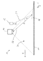
- FIG. 1 is a schematic representation of a first embodiment of the device 10 according to the invention shown in side view.
- the device 10 comprises a conveyor 11, by means of which the products 12 are continuously conveyed in a conveying direction F.
- the conveyor 11 is designed as an endless conveyor.
- the products 12 are preferably parts of slaughtered carcasses, for example fish, meat or poultry parts. Most preferably, the products are 12 fish fillets of tuna.
- the device 10 further comprises a light source 13.
- the light source 13 is set up and designed so that it emits a flat light field 31, wherein the planar light field 31 forms a transverse to the conveying direction F light line.
- the light source 13 is formed and arranged to form a line of light on the product 12, which is transverse to the conveying direction F.
- the device 10 further comprises a detection device 14 with an optical sensor means.
- the detection device 14 comprises a plurality of sensor means.
- the optical sensor means is designed and arranged to receive the light portions (32) reflected by the product 12.
- the optical sensor means is formed for example as a CCD camera or as a CCD line scan camera.
- the light source 13 is an infrared light source.
- the light source 13 is designed to emit light in the infrared wavelength range.
- the light source 13 comprises a wavelength range from the infrared range to the visible red.
- the light source 13 is arranged such that the plane of the planar light field 31 is inclined relative to the conveying direction F by a light field angle ⁇ of less than 90 °.
- the plane is preferably not aligned orthogonal to the conveying direction F, so that the plane of the flat light field 31 does not meet perpendicular to the surface of the products 12, but is inclined by a corresponding angular amount.
- the oblique position of the planar light field 31 leads to a deformation of the lines of light on the product 12 as a function of the geometry of the product 12, so that the shape and geometry of the product 12 can be deduced based on the course of the light lines.
- the optical sensor means of the detection means 14 is adapted to receive images of the corresponding according to the geometry of the product 12 extending light lines and arranged and adapted to the respective wavelengths of the light emitted from the light source 13.
- the detection device 14 may also comprise further optical sensors which are suitable for recording images or image data in another, for example in the visible, wavelength range are formed and set up.
- the detection device 14 is set up in this case for processing the signals of a plurality of the optical sensors.
- the detection device 14 has processing means for superimposing the captured images of a plurality of the optical sensors.
- a further light source - not shown in the drawing - for illuminating the product 12 with light of visible wavelength is arranged.
- the detection device 14 includes in addition to the optical sensor means for receiving images of the product 12 and extending therefrom light lines in the infrared range, is additionally another - not shown in the drawing-optical sensor means for receiving images of the product 12, in the visible light wavelength range arranged.
- the optical sensor means and the further optical sensor means are as an integral sensor means, i. together as a sensor means.
- this one sensor means is designed as a camera that is sensitive to both the infrared and the visible light wavelength range.
- the detection device 14 preferably comprises only one sensor means which is designed and set up both for recording images in the infrared and in the visible light wavelength range.
- the detection device 14 is preferably adapted to determine additional information about the nature, in particular the geometry, of the products 12 by means of the processing means by combining the recorded images in the visible and in the infrared light wavelength range. For example, it is possible in this way to determine geometric data of the product 12, such as the product width or the product contour.
- red tissue structures 16 is red muscle meat.
- the present invention is not limited to the detection of the red muscle meat 16 in tuna, but is basically suitable for other products 12, so for example for fillets or meat components of other species.
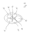
- the Indian FIG. 2 The highly schematized cross-section of a tuna shows the muscle strands 15, which enclose the red blood cells with red blood cells.
- the red tissue structures 16 in turn surround the spinal column 17. Between the spine 17 and the abdominal cavity 18, a large blood vessel 19 is arranged, which among other things is responsible for the strong perfusion of the red muscle meat.
- the muscle strands 15 as well as the red muscle meat are translucent tissues.
- the muscle strands 15 and the red tissue structures 16 with the red muscle meat have different opacities, ie a different light transmittance. Due to the different opacities, the light line at the surface of the product 12 appears to have different widths.
- the detection device 14 is designed and set up for evaluating the images recorded by means of the optical sensor, in particular by evaluating the width of the light lines for detecting the red muscle meat.
- the light source 13 and the optical sensor means are arranged spaced from each other, that is, the light source 13 and the optical sensor means with respect to the conveying direction F arranged at a distance from each other, for example, to determine the height contour of the product 12.
- the viewing angle ⁇ in this case denotes the angle between the conveying direction F and the reflected light components 32.
- the light source 13 and the detection device 14 are arranged such that both the illumination of the product 12 by means of the flat light field 31 and the recording of the Product 12 reflected light portions 32 is made under inclination.
- the light source 13 and the detection device 14 are further arranged such that the light field angle ⁇ is greater than the viewing angle ⁇ .
- the angular difference ⁇ between the light field angle ⁇ and the viewing angle ⁇ denotes the angle between the flat light field 31 incident on the product 12 and the reflected light portions 32.
- the detection device 14 of the light source 13 is arranged downstream in the conveying direction F.
- the detection device 14 and the light source 13 are arranged such that the products 12 are illuminated obliquely inclined counter to the conveying direction F and the reflected light portions 32 have at least one sub-component, which also points in the conveying direction F.
- the light source 13 is formed as a line laser.
- line lasers with a power of 5 to 500 mW are used.
- the light source 13 is a conventional light source with a correspondingly high luminous flux and an adapted optics for generating the above-described two-dimensional light field 31 as well as the light line running on the product 12.
- the light source 13 has a wavelength between 600 nm and 1200 nm, i. a wavelength range extending from the visible red to the infrared range. More preferably, the light source 13 has a wavelength in the range between 650 and 900 nm, and is thus optimally adapted to the absorption properties of strongly perfused tissues, such as the red tissue structures 16.
- the detection device 14 is designed and arranged for taking a plurality of individual images of the product 12.
- the detection device 14 is set up in such a way that a plurality of individual images are produced by the product 12, which represent a plurality of segments of the continuously conveyed product 12.
- the detection device 14 comprises an evaluation, which is designed and set up for the evaluation of individual images taken.
- the evaluation means is further for determining boundary lines between the areas of red tissue structures 16, in particular of the red muscle meat and the remaining product areas 33, for example, the muscle strands 15, formed and set up based on the individual images.
- the evaluation means is designed and set up to determine lines of equal light intensity in the individual images for determining the boundary lines.
- the boundary lines define the transition between the red tissue structures 16 and the remaining tissue parts, in particular the muscle strands 15.
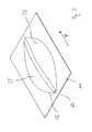
- FIG. 3 schematically a tuna fillet including a part of the conveyor 11 is shown in a perspective view.
- the aforementioned region of the red tissue structures 16 is as a strip of red muscle meat FIG. 3 refer to.
- the product 12, for example a fish fillet of tuna fish, is aligned along the spinal column 17 in the conveying direction F and is conveyed by means of - in the FIG. 3 only schematically indicated - conveyor 11 continuously conveyed.
- the present invention also encompasses an arrangement for detaching the strip 20 of red tissue structures 16 from the products 12.
- the arrangement comprises the above-described device for non-contact detection of the red tissue structures 16 in the product 12 or in the products 12 Arrangement of a cutting device 21 not shown in the figures.
- the cutting device 21 is designed and arranged for the partial or complete release of the strip 20 of the red fabric structures 16 from the products 12.
- the cutting device 21 is controlled by means of a - not shown in the drawing - control device.
- the control device controls the cutting device 21 in such a way that the areas determined by means of the device according to the invention for non-contact detection of the red tissue structures 16, in particular the strip 20, are completely or partially detached from the products 12.
- the cutting device is optionally arranged such that either the strip 20 is completely released from the product 12 or only a partial release takes place by the strip 20 is released by cuts or cuts in the product 12 in partial areas, but after the Cutting with it the product 12 is connected, for example, to be finally released from the product 12 by means of a subsequent manual processing.
- the cutting device 21 is designed to be movable relative to the product 12, so that the distance, in particular the vertical distance, between the product 12 and the cutting device 21 is designed to be variable.
- the cutting device 21 comprises at least one - not shown in the drawing - actuator.
- the actuator By means of the actuator, the cutting device 21 is controllably formed, i. the position of the cutting device 21 is set changeable relative to the product 12 or relative to the conveyor 11.
- the control device the cutting device is controlled in its position such that the red fabric structures or the strip 20 is partially or completely released from the product 12.
- the cutting device 21 is in height, i. the distance between the respective cutting edge and the product 12, set changeable. In this way, the insertion depth of the cutting device 21 into the product 12 for the partial or complete release of the red fabric structures 16 and the strip 20 is formed variable.
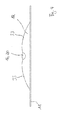
- FIG. 4 shows a schematic representation of the in the FIG. 3 shown tuna fillets and the part of the conveying device 11 in cross section.
- the conveying direction F shows in the FIG. 4 into the drawing plane.
- the area of the red tissue structures 16 of the red muscle meat in the form of the strip 20 can be seen in the middle, to which the remaining product areas 33 adjoin on both sides.
- the present invention also includes a method for non-contact detection of red tissue structures 16 in products 12 of slaughtered carcasses.
- a method for non-contact detection of red tissue structures 16 in products 12 of slaughtered carcasses To avoid repetition, in connection with the method according to the invention, reference is made in full to the statements made above with regard to the device 10 according to the invention and the arrangement according to the invention. The statements in connection with the device 10 and the Arrangement relate in an analogous manner, the inventive method. To clarify the sequence of the method according to the invention, additional aspects of the method which will be selected below are described below.
- the method of the aforementioned type comprises the following steps.
- the products 12 are conveyed continuously in the conveying direction F through an inspection area 30.
- the inspection area 30 is characterized by in the FIG. 1 shown light source 13 and the detection device 14 is formed.
- the inspection area 30 comprises the in the FIG. 1 By the dashed lines limited detection range of the detection device 14.
- the products 12 are acted upon by a flat light field 31, the light source 13 and the radiated from this area light field 31 is formed to form a transverse to the conveying direction F light line ,
- the light portions 32 reflected by the product 12 are picked up by the optical sensor means of the detection means 14.
- Reflected light components 32 denote both directly reflected light components 32 on the product surface, but in particular the light components which penetrate into deeper layers of the product and are scattered there.
- the application of light to the products 12 takes place by means of the light source 13, which is designed as an infrared light source.
- the plane of the two-dimensional light field is inclined relative to the conveyor 11 by a light field angle ⁇ of less than 90 °.
Landscapes
- Life Sciences & Earth Sciences (AREA)
- Engineering & Computer Science (AREA)
- Physics & Mathematics (AREA)
- Food Science & Technology (AREA)
- Health & Medical Sciences (AREA)
- Chemical & Material Sciences (AREA)
- General Physics & Mathematics (AREA)
- Zoology (AREA)
- Wood Science & Technology (AREA)
- Biochemistry (AREA)
- Pathology (AREA)
- Immunology (AREA)
- General Health & Medical Sciences (AREA)
- Analytical Chemistry (AREA)
- Spectroscopy & Molecular Physics (AREA)
- Medicinal Chemistry (AREA)
- Biophysics (AREA)
- Computer Vision & Pattern Recognition (AREA)
- Investigating Or Analysing Materials By Optical Means (AREA)
- Processing Of Meat And Fish (AREA)
Priority Applications (6)
| Application Number | Priority Date | Filing Date | Title |
|---|---|---|---|
| ES13151359T ES2819195T5 (es) | 2013-01-15 | 2013-01-15 | Dispositivo y procedimiento para la detección sin contacto de estructuras de tejido rojas, así como disposición para desprender una banda de estructuras de tejido rojas |
| EP13151359.0A EP2755018B2 (fr) | 2013-01-15 | 2013-01-15 | Dispositif et procédé de reconnaissance sans contact de structures tissulaires rouges ainsi qu'agencement de dissolution d'une bande de structure tissulaire rouge |
| US14/760,826 US9351498B2 (en) | 2013-01-15 | 2014-01-14 | Device and method for non-contact identifying of red tissue structures and assembly for removing a strip of red tissue structures |
| JP2015553057A JP6006435B2 (ja) | 2013-01-15 | 2014-01-14 | 赤身組織構造を非接触で識別する装置及び方法、及び赤身組織構造の条片を除去する組立体 |
| CN201480004774.XA CN104919273B (zh) | 2013-01-15 | 2014-01-14 | 红色组织结构的非接触式识别装置和方法,以及去除红色组织结构的肌肉带的总成 |
| PCT/EP2014/050589 WO2014111375A1 (fr) | 2013-01-15 | 2014-01-14 | Dispositif et procédé de détection sans contact de structures tissulaires rouges ainsi que système pour détacher une bande de structures tissulaires rouges |
Applications Claiming Priority (1)
| Application Number | Priority Date | Filing Date | Title |
|---|---|---|---|
| EP13151359.0A EP2755018B2 (fr) | 2013-01-15 | 2013-01-15 | Dispositif et procédé de reconnaissance sans contact de structures tissulaires rouges ainsi qu'agencement de dissolution d'une bande de structure tissulaire rouge |
Publications (4)
| Publication Number | Publication Date |
|---|---|
| EP2755018A1 true EP2755018A1 (fr) | 2014-07-16 |
| EP2755018A9 EP2755018A9 (fr) | 2014-10-08 |
| EP2755018B1 EP2755018B1 (fr) | 2020-07-22 |
| EP2755018B2 EP2755018B2 (fr) | 2024-04-03 |
Family
ID=47605377
Family Applications (1)
| Application Number | Title | Priority Date | Filing Date |
|---|---|---|---|
| EP13151359.0A Active EP2755018B2 (fr) | 2013-01-15 | 2013-01-15 | Dispositif et procédé de reconnaissance sans contact de structures tissulaires rouges ainsi qu'agencement de dissolution d'une bande de structure tissulaire rouge |
Country Status (6)
| Country | Link |
|---|---|
| US (1) | US9351498B2 (fr) |
| EP (1) | EP2755018B2 (fr) |
| JP (1) | JP6006435B2 (fr) |
| CN (1) | CN104919273B (fr) |
| ES (1) | ES2819195T5 (fr) |
| WO (1) | WO2014111375A1 (fr) |
Cited By (8)
| Publication number | Priority date | Publication date | Assignee | Title |
|---|---|---|---|---|
| CN105044112A (zh) * | 2015-08-10 | 2015-11-11 | 苏州听毅华自动化设备有限公司 | 一种管件焊接线检测装置 |
| CN106516647A (zh) * | 2016-10-21 | 2017-03-22 | 山东科技大学 | 一种矿车运输智能煤矸识别及分运装置 |
| WO2020036620A1 (fr) * | 2018-08-16 | 2020-02-20 | Thai Union Group Public Company Limited | Système d'imagerie à vues multiples et procédés d'inspection non invasive dans le traitement d'aliments |
| WO2020207569A1 (fr) * | 2019-04-09 | 2020-10-15 | Nordischer Maschinenbau Rud. Baader Gmbh + Co. Kg | Ensemble et procédé d'élimination automatique d'une bande constituée de ce que l'on appelle "chair grise" sur un filet de poisson |
| US11120540B2 (en) | 2018-08-16 | 2021-09-14 | Thai Union Group Public Company Limited | Multi-view imaging system and methods for non-invasive inspection in food processing |
| US11202452B2 (en) | 2019-04-08 | 2021-12-21 | Provisor Technologies, Inc. | Apparatus and method for cutting meat products into blocks of meat |
| US12310375B2 (en) | 2019-04-18 | 2025-05-27 | Provisur Technologies, Inc. | Food processing apparatus and corresponding food processing method |
| US12311567B2 (en) | 2021-10-25 | 2025-05-27 | Provisur Technologies, Inc. | Releasable side strapping assembly for a food product slicing apparatus |
Families Citing this family (5)
| Publication number | Priority date | Publication date | Assignee | Title |
|---|---|---|---|---|
| WO2017121713A1 (fr) | 2016-01-11 | 2017-07-20 | Teknologisk Institut | Procédé et dispositif de balayage d'objets au moyen d'une combinaison de plages spectrales dans le visible, le proche ir et les rayons x |
| CN108828167A (zh) * | 2018-07-05 | 2018-11-16 | 中国水产科学研究院黄海水产研究所 | 一种生食北方蓝鳍金枪鱼肉等级的快速评定方法 |
| EP3897168A1 (fr) * | 2019-04-09 | 2021-10-27 | Nordischer Maschinenbau Rud. Baader Gmbh + Co Kg | Dispositif de coupe permettant de découper une bande, sensiblement en forme de v, de produits carnés alimentés dans une direction de transport t ainsi que procédé et dispositif permettant l'élimination d'une bande, sensiblement en forme de v, de produits carnés alimentés dans une direction de transport t avec un tel dispositif de coupe |
| NL2023271B1 (en) * | 2019-06-06 | 2020-12-22 | Aweta G&P B V | Apparatus and method for determining a property of products |
| JP7408143B2 (ja) * | 2020-03-06 | 2024-01-05 | ヤマキ株式会社 | 血合い除去装置 |
Citations (3)
| Publication number | Priority date | Publication date | Assignee | Title |
|---|---|---|---|---|
| US3800363A (en) * | 1972-12-29 | 1974-04-02 | Laitram Corp | Tuna butchering method and system |
| WO1989012397A1 (fr) * | 1988-06-23 | 1989-12-28 | Lumetech A/S | Procede de localisation de certaines regions dans un morceau de viande et notamment dans un poisson, soumis initialement a un eclairage |
| WO2008016309A1 (fr) * | 2006-08-04 | 2008-02-07 | Sinvent As | Contrôle de qualité de produits alimentaires multimodal à vision artificielle |
Family Cites Families (19)
| Publication number | Priority date | Publication date | Assignee | Title |
|---|---|---|---|---|
| JPS6027334A (ja) * | 1983-07-25 | 1985-02-12 | 松本 欣二 | 魚の血合肉除去装置 |
| US4557019A (en) | 1984-08-10 | 1985-12-10 | Seafreeze Limited Partnership | Automatic portion-cutting method and machine |
| USRE33917E (en) * | 1987-05-12 | 1992-05-05 | The Laitram Corporation | Support apparatus for use in video imaging and processing of transverse fish sections |
| JPH0718815B2 (ja) * | 1989-06-27 | 1995-03-06 | 松下電工株式会社 | 表面検査機 |
| JPH04164285A (ja) * | 1990-10-29 | 1992-06-09 | Hochiki Corp | 光線式検出器 |
| US5471311A (en) † | 1991-10-01 | 1995-11-28 | Van Den Bergh; Herman | Information system for monitoring products in sorting apparatus |
| GB9127139D0 (en) | 1991-12-20 | 1992-02-19 | 3D Scanners Ltd | Scanning unit |
| US5324228A (en) * | 1992-07-27 | 1994-06-28 | Frigoscandia Food Processing Systems A.B. | Method and apparatus for detecting and trimming fat from meat products |
| JP2003506676A (ja) | 1999-07-28 | 2003-02-18 | マリーン・ハーベスト・ノルウェー・エーエス | 魚の品質特性を測定するための方法並びに装置 |
| US6369401B1 (en) | 1999-09-10 | 2002-04-09 | Agri-Tech, Inc. | Three-dimensional optical volume measurement for objects to be categorized |
| GB2364894B8 (en) * | 2000-07-19 | 2010-07-07 | Fmc Corp | Three axis portioning method |
| DE10358487B3 (de) * | 2003-12-13 | 2005-05-25 | Csb-System Ag | Verfahren zum Ermitteln der Qualität und Quantitäten eines Schlachttierkörpers |
| AU2005248942A1 (en) * | 2004-12-30 | 2006-07-20 | John Bean Technologies Corporation | Conveying conformable products |
| WO2006086450A1 (fr) * | 2005-02-08 | 2006-08-17 | Cargill Incorporated | Tri de viande |
| EP1887874B1 (fr) * | 2005-05-31 | 2012-08-01 | Teknologisk Institut | Procede et usage d'une base de données permettant de determiner automatiquement les caracteristiques de qualite d'une carcasse sur une chaine d'abattage |
| CN100480680C (zh) * | 2007-05-22 | 2009-04-22 | 浙江大学 | 多光谱肉类新鲜度人工智能测量方法及系统 |
| DE102008013525B4 (de) | 2008-03-08 | 2010-07-29 | Nordischer Maschinenbau Rud. Baader Gmbh + Co Kg | Vorrichtung und Verfahren zum kontaktlosen Erkennen von Charakteristika von kontinuierlich geförderten, transluzenten Produkten |
| JP2010044049A (ja) * | 2008-07-15 | 2010-02-25 | Toppan Printing Co Ltd | 塗工検査方法および塗工検査装置および塗工装置 |
| CN101551341B (zh) * | 2009-04-09 | 2011-02-16 | 浙江大学 | 基于图像与光谱信息融合的肉品在线无损检测方法与装置 |
-
2013
- 2013-01-15 EP EP13151359.0A patent/EP2755018B2/fr active Active
- 2013-01-15 ES ES13151359T patent/ES2819195T5/es active Active
-
2014
- 2014-01-14 CN CN201480004774.XA patent/CN104919273B/zh active Active
- 2014-01-14 JP JP2015553057A patent/JP6006435B2/ja active Active
- 2014-01-14 WO PCT/EP2014/050589 patent/WO2014111375A1/fr not_active Ceased
- 2014-01-14 US US14/760,826 patent/US9351498B2/en active Active
Patent Citations (3)
| Publication number | Priority date | Publication date | Assignee | Title |
|---|---|---|---|---|
| US3800363A (en) * | 1972-12-29 | 1974-04-02 | Laitram Corp | Tuna butchering method and system |
| WO1989012397A1 (fr) * | 1988-06-23 | 1989-12-28 | Lumetech A/S | Procede de localisation de certaines regions dans un morceau de viande et notamment dans un poisson, soumis initialement a un eclairage |
| WO2008016309A1 (fr) * | 2006-08-04 | 2008-02-07 | Sinvent As | Contrôle de qualité de produits alimentaires multimodal à vision artificielle |
Cited By (15)
| Publication number | Priority date | Publication date | Assignee | Title |
|---|---|---|---|---|
| CN105044112A (zh) * | 2015-08-10 | 2015-11-11 | 苏州听毅华自动化设备有限公司 | 一种管件焊接线检测装置 |
| CN106516647A (zh) * | 2016-10-21 | 2017-03-22 | 山东科技大学 | 一种矿车运输智能煤矸识别及分运装置 |
| WO2020036620A1 (fr) * | 2018-08-16 | 2020-02-20 | Thai Union Group Public Company Limited | Système d'imagerie à vues multiples et procédés d'inspection non invasive dans le traitement d'aliments |
| US11120540B2 (en) | 2018-08-16 | 2021-09-14 | Thai Union Group Public Company Limited | Multi-view imaging system and methods for non-invasive inspection in food processing |
| US11202452B2 (en) | 2019-04-08 | 2021-12-21 | Provisor Technologies, Inc. | Apparatus and method for cutting meat products into blocks of meat |
| US11627745B2 (en) | 2019-04-08 | 2023-04-18 | Provisur Technologies, Inc. | Apparatus and method for flattening meat products |
| WO2020207569A1 (fr) * | 2019-04-09 | 2020-10-15 | Nordischer Maschinenbau Rud. Baader Gmbh + Co. Kg | Ensemble et procédé d'élimination automatique d'une bande constituée de ce que l'on appelle "chair grise" sur un filet de poisson |
| TWI749512B (zh) * | 2019-04-09 | 2021-12-11 | 德商諾迪許機械製造盧德巴德有限+兩合公司 | 用於從魚片自動移除由紅肉即所謂的深色肉組成之條的裝置及方法 |
| US12557820B2 (en) | 2019-04-09 | 2026-02-24 | Nordischer Maschinenbau Rud. Baader Gmbh + Co. Kg | Arrangement and method for automatically removing a strip consisting of dark meat from a fish fillet |
| US12310375B2 (en) | 2019-04-18 | 2025-05-27 | Provisur Technologies, Inc. | Food processing apparatus and corresponding food processing method |
| US12311567B2 (en) | 2021-10-25 | 2025-05-27 | Provisur Technologies, Inc. | Releasable side strapping assembly for a food product slicing apparatus |
| US12427687B2 (en) | 2021-10-25 | 2025-09-30 | Provisur Technologies, Inc. | Profile scanner and feed assembly for a high-speed food slicing apparatus |
| US12441021B2 (en) | 2021-10-25 | 2025-10-14 | Provisur Technologies, Inc. | Blade assembly and counterweight mechanism for a high-speed food slicing apparatus, and methods associated with the same |
| US12558808B2 (en) | 2021-10-25 | 2026-02-24 | Provisur Technologies, Inc. | Blade assembly and retraction mechanism for a high-speed food slicing apparatus |
| US12570021B2 (en) | 2021-10-25 | 2026-03-10 | Provisur Technologies, Inc. | Drive assembly for a food product slicing apparatus |
Also Published As
| Publication number | Publication date |
|---|---|
| CN104919273A (zh) | 2015-09-16 |
| WO2014111375A1 (fr) | 2014-07-24 |
| EP2755018A9 (fr) | 2014-10-08 |
| CN104919273B (zh) | 2018-06-29 |
| EP2755018B2 (fr) | 2024-04-03 |
| ES2819195T3 (es) | 2021-04-15 |
| JP2016505139A (ja) | 2016-02-18 |
| JP6006435B2 (ja) | 2016-10-12 |
| US9351498B2 (en) | 2016-05-31 |
| EP2755018B1 (fr) | 2020-07-22 |
| ES2819195T5 (es) | 2024-12-10 |
| US20150342202A1 (en) | 2015-12-03 |
Similar Documents
| Publication | Publication Date | Title |
|---|---|---|
| EP2755018B1 (fr) | Dispositif et procédé de reconnaissance sans contact de structures tissulaires rouges ainsi qu'agencement de dissolution d'une bande de structure tissulaire rouge | |
| EP1401619B1 (fr) | Procede et dispositif de decoupage | |
| DE102019103734A1 (de) | Laserbearbeitungssystem zur Bearbeitung eines Werkstücks mittels eines Laserstrahls und Verfahren zum Steuern eines Laserbearbeitungssystems | |
| DE102009022157A1 (de) | Verfahren und Einrichtung zum Herstellen von Dünnschnitten einer Probe mittels einer Bilderkennung | |
| EP3448160B1 (fr) | Procédé et dispositif d'inspection de la cavité abdominale de poissons évidés | |
| EP2495525A1 (fr) | Procédé de vérification optique à l'aide d'un déroulement d'intensité | |
| EP3581881A1 (fr) | Mesure de surface au moyen de la fluorescence excitée | |
| WO2017097959A1 (fr) | Procédé de détermination de forme | |
| EP2669622B1 (fr) | Procédé de contrôle et tête de contrôle appropriée pour celui-ci | |
| DE2422905A1 (de) | Verfahren und vorrichtung zur zerstoerungsfreien bestimmung des geschlechts von fischen | |
| EP4151948A1 (fr) | Procédé et dispositif de contrôle de la qualité d'un bord d'une pièce à usiner en forme de plaque | |
| DE3418283A1 (de) | Verfahren zum nachweis von fehlstellen in transparenten materialien | |
| EP3872446B1 (fr) | Dispositif de mesure optique | |
| EP2693403B1 (fr) | Procédé de contrôle d'une zone d'image cohérent pour rechercher des erreurs dans la zone de surface d'un objet | |
| WO2001023869A1 (fr) | Procede et dispositif pour inspecter la surface d'un feuillard circulant en continu | |
| EP2972071B1 (fr) | Dispositif de mesure d'un objet carcasse d'animal de boucherie | |
| EP3712600B1 (fr) | Procédé et dispositif d'inspection de la surface d'une bande en mouvement | |
| EP2208460A1 (fr) | Reconnaissance et localisation de tissus par analyse à la lumière | |
| EP1355148B1 (fr) | Procédure pour la détection des défectuosités, telles que fêlures ou bords chanfreinés sur la surface de planches de bois | |
| EP4010145B1 (fr) | Procédé d'analyse de la surface d'une pièce dans le cadre d'un processus d'usinage laser et dispositif d'analyse destiné à analyser la surface d'une pièce | |
| DE102017118304A1 (de) | Vorrichtung und Verfahren zum Schneiden einer Probe | |
| AT391027B (de) | Verfahren zum vermessen der kanten eines holzes im laengstransport und vorrichtung hierfuer | |
| DE102023106499A1 (de) | Entfettungsmaschine und Messeinrichtung | |
| DE102019123232A1 (de) | Mehrfach-Belichtungsverfahren | |
| DE102024120147A1 (de) | Verfahren und Vorrichtung zum Bestimmen von metrischen Daten eines oder mehrerer Merkmale eines Objekts und Computerprogramm |
Legal Events
| Date | Code | Title | Description |
|---|---|---|---|
| PUAI | Public reference made under article 153(3) epc to a published international application that has entered the european phase |
Free format text: ORIGINAL CODE: 0009012 |
|
| 17P | Request for examination filed |
Effective date: 20130115 |
|
| AK | Designated contracting states |
Kind code of ref document: A1 Designated state(s): AL AT BE BG CH CY CZ DE DK EE ES FI FR GB GR HR HU IE IS IT LI LT LU LV MC MK MT NL NO PL PT RO RS SE SI SK SM TR |
|
| AX | Request for extension of the european patent |
Extension state: BA ME |
|
| R17P | Request for examination filed (corrected) |
Effective date: 20150114 |
|
| RBV | Designated contracting states (corrected) |
Designated state(s): AL AT BE BG CH CY CZ DE DK EE ES FI FR GB GR HR HU IE IS IT LI LT LU LV MC MK MT NL NO PL PT RO RS SE SI SK SM TR |
|
| REG | Reference to a national code |
Ref country code: DE Ref legal event code: R079 Ref document number: 502013014932 Country of ref document: DE Free format text: PREVIOUS MAIN CLASS: G01N0021350000 Ipc: G01N0021940000 |
|
| GRAP | Despatch of communication of intention to grant a patent |
Free format text: ORIGINAL CODE: EPIDOSNIGR1 |
|
| STAA | Information on the status of an ep patent application or granted ep patent |
Free format text: STATUS: GRANT OF PATENT IS INTENDED |
|
| RIC1 | Information provided on ipc code assigned before grant |
Ipc: A22C 21/00 20060101ALI20190923BHEP Ipc: G01N 21/94 20060101AFI20190923BHEP Ipc: G01N 33/12 20060101ALI20190923BHEP Ipc: G01B 11/25 20060101ALI20190923BHEP Ipc: A22C 17/00 20060101ALI20190923BHEP Ipc: G01N 21/84 20060101ALI20190923BHEP Ipc: G01N 21/3563 20140101ALI20190923BHEP Ipc: A22C 25/04 20060101ALI20190923BHEP Ipc: A22C 25/18 20060101ALI20190923BHEP |
|
| INTG | Intention to grant announced |
Effective date: 20191008 |
|
| GRAJ | Information related to disapproval of communication of intention to grant by the applicant or resumption of examination proceedings by the epo deleted |
Free format text: ORIGINAL CODE: EPIDOSDIGR1 |
|
| STAA | Information on the status of an ep patent application or granted ep patent |
Free format text: STATUS: REQUEST FOR EXAMINATION WAS MADE |
|
| GRAP | Despatch of communication of intention to grant a patent |
Free format text: ORIGINAL CODE: EPIDOSNIGR1 |
|
| STAA | Information on the status of an ep patent application or granted ep patent |
Free format text: STATUS: GRANT OF PATENT IS INTENDED |
|
| INTC | Intention to grant announced (deleted) | ||
| INTG | Intention to grant announced |
Effective date: 20200205 |
|
| GRAS | Grant fee paid |
Free format text: ORIGINAL CODE: EPIDOSNIGR3 |
|
| GRAA | (expected) grant |
Free format text: ORIGINAL CODE: 0009210 |
|
| STAA | Information on the status of an ep patent application or granted ep patent |
Free format text: STATUS: THE PATENT HAS BEEN GRANTED |
|
| AK | Designated contracting states |
Kind code of ref document: B1 Designated state(s): AL AT BE BG CH CY CZ DE DK EE ES FI FR GB GR HR HU IE IS IT LI LT LU LV MC MK MT NL NO PL PT RO RS SE SI SK SM TR |
|
| REG | Reference to a national code |
Ref country code: GB Ref legal event code: FG4D Free format text: NOT ENGLISH |
|
| REG | Reference to a national code |
Ref country code: CH Ref legal event code: EP |
|
| REG | Reference to a national code |
Ref country code: DE Ref legal event code: R096 Ref document number: 502013014932 Country of ref document: DE |
|
| REG | Reference to a national code |
Ref country code: AT Ref legal event code: REF Ref document number: 1293873 Country of ref document: AT Kind code of ref document: T Effective date: 20200815 |
|
| REG | Reference to a national code |
Ref country code: IE Ref legal event code: FG4D Free format text: LANGUAGE OF EP DOCUMENT: GERMAN |
|
| REG | Reference to a national code |
Ref country code: NL Ref legal event code: FP |
|
| REG | Reference to a national code |
Ref country code: NO Ref legal event code: T2 Effective date: 20200722 |
|
| REG | Reference to a national code |
Ref country code: LT Ref legal event code: MG4D |
|
| PG25 | Lapsed in a contracting state [announced via postgrant information from national office to epo] |
Ref country code: PT Free format text: LAPSE BECAUSE OF FAILURE TO SUBMIT A TRANSLATION OF THE DESCRIPTION OR TO PAY THE FEE WITHIN THE PRESCRIBED TIME-LIMIT Effective date: 20201123 Ref country code: BG Free format text: LAPSE BECAUSE OF FAILURE TO SUBMIT A TRANSLATION OF THE DESCRIPTION OR TO PAY THE FEE WITHIN THE PRESCRIBED TIME-LIMIT Effective date: 20201022 Ref country code: LT Free format text: LAPSE BECAUSE OF FAILURE TO SUBMIT A TRANSLATION OF THE DESCRIPTION OR TO PAY THE FEE WITHIN THE PRESCRIBED TIME-LIMIT Effective date: 20200722 Ref country code: HR Free format text: LAPSE BECAUSE OF FAILURE TO SUBMIT A TRANSLATION OF THE DESCRIPTION OR TO PAY THE FEE WITHIN THE PRESCRIBED TIME-LIMIT Effective date: 20200722 Ref country code: GR Free format text: LAPSE BECAUSE OF FAILURE TO SUBMIT A TRANSLATION OF THE DESCRIPTION OR TO PAY THE FEE WITHIN THE PRESCRIBED TIME-LIMIT Effective date: 20201023 Ref country code: SE Free format text: LAPSE BECAUSE OF FAILURE TO SUBMIT A TRANSLATION OF THE DESCRIPTION OR TO PAY THE FEE WITHIN THE PRESCRIBED TIME-LIMIT Effective date: 20200722 Ref country code: FI Free format text: LAPSE BECAUSE OF FAILURE TO SUBMIT A TRANSLATION OF THE DESCRIPTION OR TO PAY THE FEE WITHIN THE PRESCRIBED TIME-LIMIT Effective date: 20200722 |
|
| PG25 | Lapsed in a contracting state [announced via postgrant information from national office to epo] |
Ref country code: RS Free format text: LAPSE BECAUSE OF FAILURE TO SUBMIT A TRANSLATION OF THE DESCRIPTION OR TO PAY THE FEE WITHIN THE PRESCRIBED TIME-LIMIT Effective date: 20200722 Ref country code: LV Free format text: LAPSE BECAUSE OF FAILURE TO SUBMIT A TRANSLATION OF THE DESCRIPTION OR TO PAY THE FEE WITHIN THE PRESCRIBED TIME-LIMIT Effective date: 20200722 Ref country code: PL Free format text: LAPSE BECAUSE OF FAILURE TO SUBMIT A TRANSLATION OF THE DESCRIPTION OR TO PAY THE FEE WITHIN THE PRESCRIBED TIME-LIMIT Effective date: 20200722 |
|
| REG | Reference to a national code |
Ref country code: ES Ref legal event code: FG2A Ref document number: 2819195 Country of ref document: ES Kind code of ref document: T3 Effective date: 20210415 |
|
| REG | Reference to a national code |
Ref country code: DE Ref legal event code: R026 Ref document number: 502013014932 Country of ref document: DE |
|
| PLBI | Opposition filed |
Free format text: ORIGINAL CODE: 0009260 |
|
| PG25 | Lapsed in a contracting state [announced via postgrant information from national office to epo] |
Ref country code: EE Free format text: LAPSE BECAUSE OF FAILURE TO SUBMIT A TRANSLATION OF THE DESCRIPTION OR TO PAY THE FEE WITHIN THE PRESCRIBED TIME-LIMIT Effective date: 20200722 Ref country code: CZ Free format text: LAPSE BECAUSE OF FAILURE TO SUBMIT A TRANSLATION OF THE DESCRIPTION OR TO PAY THE FEE WITHIN THE PRESCRIBED TIME-LIMIT Effective date: 20200722 Ref country code: DK Free format text: LAPSE BECAUSE OF FAILURE TO SUBMIT A TRANSLATION OF THE DESCRIPTION OR TO PAY THE FEE WITHIN THE PRESCRIBED TIME-LIMIT Effective date: 20200722 Ref country code: SM Free format text: LAPSE BECAUSE OF FAILURE TO SUBMIT A TRANSLATION OF THE DESCRIPTION OR TO PAY THE FEE WITHIN THE PRESCRIBED TIME-LIMIT Effective date: 20200722 Ref country code: RO Free format text: LAPSE BECAUSE OF FAILURE TO SUBMIT A TRANSLATION OF THE DESCRIPTION OR TO PAY THE FEE WITHIN THE PRESCRIBED TIME-LIMIT Effective date: 20200722 |
|
| PLAX | Notice of opposition and request to file observation + time limit sent |
Free format text: ORIGINAL CODE: EPIDOSNOBS2 |
|
| 26 | Opposition filed |
Opponent name: MAREL POULTRY B.V. Effective date: 20210422 |
|
| PG25 | Lapsed in a contracting state [announced via postgrant information from national office to epo] |
Ref country code: AL Free format text: LAPSE BECAUSE OF FAILURE TO SUBMIT A TRANSLATION OF THE DESCRIPTION OR TO PAY THE FEE WITHIN THE PRESCRIBED TIME-LIMIT Effective date: 20200722 |
|
| PG25 | Lapsed in a contracting state [announced via postgrant information from national office to epo] |
Ref country code: SK Free format text: LAPSE BECAUSE OF FAILURE TO SUBMIT A TRANSLATION OF THE DESCRIPTION OR TO PAY THE FEE WITHIN THE PRESCRIBED TIME-LIMIT Effective date: 20200722 |
|
| PG25 | Lapsed in a contracting state [announced via postgrant information from national office to epo] |
Ref country code: MC Free format text: LAPSE BECAUSE OF FAILURE TO SUBMIT A TRANSLATION OF THE DESCRIPTION OR TO PAY THE FEE WITHIN THE PRESCRIBED TIME-LIMIT Effective date: 20200722 Ref country code: SI Free format text: LAPSE BECAUSE OF FAILURE TO SUBMIT A TRANSLATION OF THE DESCRIPTION OR TO PAY THE FEE WITHIN THE PRESCRIBED TIME-LIMIT Effective date: 20200722 |
|
| REG | Reference to a national code |
Ref country code: CH Ref legal event code: PL |
|
| PLBB | Reply of patent proprietor to notice(s) of opposition received |
Free format text: ORIGINAL CODE: EPIDOSNOBS3 |
|
| GBPC | Gb: european patent ceased through non-payment of renewal fee |
Effective date: 20210115 |
|
| PG25 | Lapsed in a contracting state [announced via postgrant information from national office to epo] |
Ref country code: LU Free format text: LAPSE BECAUSE OF NON-PAYMENT OF DUE FEES Effective date: 20210115 |
|
| REG | Reference to a national code |
Ref country code: BE Ref legal event code: MM Effective date: 20210131 |
|
| PG25 | Lapsed in a contracting state [announced via postgrant information from national office to epo] |
Ref country code: CH Free format text: LAPSE BECAUSE OF NON-PAYMENT OF DUE FEES Effective date: 20210131 Ref country code: GB Free format text: LAPSE BECAUSE OF NON-PAYMENT OF DUE FEES Effective date: 20210115 Ref country code: LI Free format text: LAPSE BECAUSE OF NON-PAYMENT OF DUE FEES Effective date: 20210131 |
|
| PG25 | Lapsed in a contracting state [announced via postgrant information from national office to epo] |
Ref country code: IE Free format text: LAPSE BECAUSE OF NON-PAYMENT OF DUE FEES Effective date: 20210115 |
|
| REG | Reference to a national code |
Ref country code: AT Ref legal event code: MM01 Ref document number: 1293873 Country of ref document: AT Kind code of ref document: T Effective date: 20210115 |
|
| PG25 | Lapsed in a contracting state [announced via postgrant information from national office to epo] |
Ref country code: AT Free format text: LAPSE BECAUSE OF NON-PAYMENT OF DUE FEES Effective date: 20210115 |
|
| PG25 | Lapsed in a contracting state [announced via postgrant information from national office to epo] |
Ref country code: BE Free format text: LAPSE BECAUSE OF NON-PAYMENT OF DUE FEES Effective date: 20210131 |
|
| PG25 | Lapsed in a contracting state [announced via postgrant information from national office to epo] |
Ref country code: HU Free format text: LAPSE BECAUSE OF FAILURE TO SUBMIT A TRANSLATION OF THE DESCRIPTION OR TO PAY THE FEE WITHIN THE PRESCRIBED TIME-LIMIT; INVALID AB INITIO Effective date: 20130115 |
|
| P01 | Opt-out of the competence of the unified patent court (upc) registered |
Effective date: 20230517 |
|
| PG25 | Lapsed in a contracting state [announced via postgrant information from national office to epo] |
Ref country code: CY Free format text: LAPSE BECAUSE OF FAILURE TO SUBMIT A TRANSLATION OF THE DESCRIPTION OR TO PAY THE FEE WITHIN THE PRESCRIBED TIME-LIMIT Effective date: 20200722 |
|
| APBM | Appeal reference recorded |
Free format text: ORIGINAL CODE: EPIDOSNREFNO |
|
| APBP | Date of receipt of notice of appeal recorded |
Free format text: ORIGINAL CODE: EPIDOSNNOA2O |
|
| APAH | Appeal reference modified |
Free format text: ORIGINAL CODE: EPIDOSCREFNO |
|
| APBU | Appeal procedure closed |
Free format text: ORIGINAL CODE: EPIDOSNNOA9O |
|
| APAN | Information on closure of appeal procedure modified |
Free format text: ORIGINAL CODE: EPIDOSCNOA9O |
|
| PUAH | Patent maintained in amended form |
Free format text: ORIGINAL CODE: 0009272 |
|
| STAA | Information on the status of an ep patent application or granted ep patent |
Free format text: STATUS: PATENT MAINTAINED AS AMENDED |
|
| 27A | Patent maintained in amended form |
Effective date: 20240403 |
|
| AK | Designated contracting states |
Kind code of ref document: B2 Designated state(s): AL AT BE BG CH CY CZ DE DK EE ES FI FR GB GR HR HU IE IS IT LI LT LU LV MC MK MT NL NO PL PT RO RS SE SI SK SM TR |
|
| REG | Reference to a national code |
Ref country code: DE Ref legal event code: R102 Ref document number: 502013014932 Country of ref document: DE |
|
| PG25 | Lapsed in a contracting state [announced via postgrant information from national office to epo] |
Ref country code: MK Free format text: LAPSE BECAUSE OF FAILURE TO SUBMIT A TRANSLATION OF THE DESCRIPTION OR TO PAY THE FEE WITHIN THE PRESCRIBED TIME-LIMIT Effective date: 20200722 |
|
| PG25 | Lapsed in a contracting state [announced via postgrant information from national office to epo] |
Ref country code: TR Free format text: LAPSE BECAUSE OF FAILURE TO SUBMIT A TRANSLATION OF THE DESCRIPTION OR TO PAY THE FEE WITHIN THE PRESCRIBED TIME-LIMIT Effective date: 20200722 |
|
| REG | Reference to a national code |
Ref country code: NL Ref legal event code: FP |
|
| PG25 | Lapsed in a contracting state [announced via postgrant information from national office to epo] |
Ref country code: MT Free format text: LAPSE BECAUSE OF FAILURE TO SUBMIT A TRANSLATION OF THE DESCRIPTION OR TO PAY THE FEE WITHIN THE PRESCRIBED TIME-LIMIT Effective date: 20200722 |
|
| REG | Reference to a national code |
Ref country code: ES Ref legal event code: DC2A Ref document number: 2819195 Country of ref document: ES Kind code of ref document: T5 Effective date: 20241210 |
|
| PGFP | Annual fee paid to national office [announced via postgrant information from national office to epo] |
Ref country code: IS Payment date: 20251212 Year of fee payment: 14 |
|
| PGFP | Annual fee paid to national office [announced via postgrant information from national office to epo] |
Ref country code: NL Payment date: 20260121 Year of fee payment: 14 |
|
| PGFP | Annual fee paid to national office [announced via postgrant information from national office to epo] |
Ref country code: ES Payment date: 20260217 Year of fee payment: 14 |
|
| PGFP | Annual fee paid to national office [announced via postgrant information from national office to epo] |
Ref country code: NO Payment date: 20260120 Year of fee payment: 14 Ref country code: DE Payment date: 20260120 Year of fee payment: 14 |
|
| PGFP | Annual fee paid to national office [announced via postgrant information from national office to epo] |
Ref country code: IT Payment date: 20260130 Year of fee payment: 14 |
|
| PGFP | Annual fee paid to national office [announced via postgrant information from national office to epo] |
Ref country code: FR Payment date: 20260121 Year of fee payment: 14 |