EP2755283A2 - Benutzerkonfigurierbarer Stecker - Google Patents
Benutzerkonfigurierbarer Stecker Download PDFInfo
- Publication number
- EP2755283A2 EP2755283A2 EP13173164.8A EP13173164A EP2755283A2 EP 2755283 A2 EP2755283 A2 EP 2755283A2 EP 13173164 A EP13173164 A EP 13173164A EP 2755283 A2 EP2755283 A2 EP 2755283A2
- Authority
- EP
- European Patent Office
- Prior art keywords
- connector
- connector body
- retainer
- proximal end
- latch
- Prior art date
- Legal status (The legal status is an assumption and is not a legal conclusion. Google has not performed a legal analysis and makes no representation as to the accuracy of the status listed.)
- Granted
Links
Images


Classifications
-
- H—ELECTRICITY
- H01—ELECTRIC ELEMENTS
- H01R—ELECTRICALLY-CONDUCTIVE CONNECTIONS; STRUCTURAL ASSOCIATIONS OF A PLURALITY OF MUTUALLY-INSULATED ELECTRICAL CONNECTING ELEMENTS; COUPLING DEVICES; CURRENT COLLECTORS
- H01R13/00—Details of coupling devices of the kinds covered by groups H01R12/70 or H01R24/00 - H01R33/00
- H01R13/40—Securing contact members in or to a base or case; Insulating of contact members
- H01R13/42—Securing in a demountable manner
- H01R13/424—Securing in base or case composed of a plurality of insulating parts having at least one resilient insulating part
-
- H—ELECTRICITY
- H01—ELECTRIC ELEMENTS
- H01R—ELECTRICALLY-CONDUCTIVE CONNECTIONS; STRUCTURAL ASSOCIATIONS OF A PLURALITY OF MUTUALLY-INSULATED ELECTRICAL CONNECTING ELEMENTS; COUPLING DEVICES; CURRENT COLLECTORS
- H01R13/00—Details of coupling devices of the kinds covered by groups H01R12/70 or H01R24/00 - H01R33/00
- H01R13/62—Means for facilitating engagement or disengagement of coupling parts or for holding them in engagement
- H01R13/639—Additional means for holding or locking coupling parts together, after engagement, e.g. separate keylock, retainer strap
-
- H—ELECTRICITY
- H01—ELECTRIC ELEMENTS
- H01R—ELECTRICALLY-CONDUCTIVE CONNECTIONS; STRUCTURAL ASSOCIATIONS OF A PLURALITY OF MUTUALLY-INSULATED ELECTRICAL CONNECTING ELEMENTS; COUPLING DEVICES; CURRENT COLLECTORS
- H01R13/00—Details of coupling devices of the kinds covered by groups H01R12/70 or H01R24/00 - H01R33/00
- H01R13/40—Securing contact members in or to a base or case; Insulating of contact members
- H01R13/405—Securing in non-demountable manner, e.g. moulding, riveting
- H01R13/41—Securing in non-demountable manner, e.g. moulding, riveting by frictional grip in grommet, panel or base
-
- H—ELECTRICITY
- H01—ELECTRIC ELEMENTS
- H01R—ELECTRICALLY-CONDUCTIVE CONNECTIONS; STRUCTURAL ASSOCIATIONS OF A PLURALITY OF MUTUALLY-INSULATED ELECTRICAL CONNECTING ELEMENTS; COUPLING DEVICES; CURRENT COLLECTORS
- H01R13/00—Details of coupling devices of the kinds covered by groups H01R12/70 or H01R24/00 - H01R33/00
- H01R13/46—Bases; Cases
- H01R13/52—Dustproof, splashproof, drip-proof, waterproof, or flameproof cases
- H01R13/521—Sealing between contact members and housing, e.g. sealing insert
-
- H—ELECTRICITY
- H01—ELECTRIC ELEMENTS
- H01R—ELECTRICALLY-CONDUCTIVE CONNECTIONS; STRUCTURAL ASSOCIATIONS OF A PLURALITY OF MUTUALLY-INSULATED ELECTRICAL CONNECTING ELEMENTS; COUPLING DEVICES; CURRENT COLLECTORS
- H01R43/00—Apparatus or processes specially adapted for manufacturing, assembling, maintaining, or repairing of line connectors or current collectors or for joining electric conductors
- H01R43/20—Apparatus or processes specially adapted for manufacturing, assembling, maintaining, or repairing of line connectors or current collectors or for joining electric conductors for assembling or disassembling contact members with insulating base, case or sleeve
-
- H—ELECTRICITY
- H01—ELECTRIC ELEMENTS
- H01R—ELECTRICALLY-CONDUCTIVE CONNECTIONS; STRUCTURAL ASSOCIATIONS OF A PLURALITY OF MUTUALLY-INSULATED ELECTRICAL CONNECTING ELEMENTS; COUPLING DEVICES; CURRENT COLLECTORS
- H01R13/00—Details of coupling devices of the kinds covered by groups H01R12/70 or H01R24/00 - H01R33/00
- H01R13/62—Means for facilitating engagement or disengagement of coupling parts or for holding them in engagement
- H01R13/627—Snap or like fastening
- H01R13/6271—Latching means integral with the housing
- H01R13/6273—Latching means integral with the housing comprising two latching arms
-
- H—ELECTRICITY
- H01—ELECTRIC ELEMENTS
- H01R—ELECTRICALLY-CONDUCTIVE CONNECTIONS; STRUCTURAL ASSOCIATIONS OF A PLURALITY OF MUTUALLY-INSULATED ELECTRICAL CONNECTING ELEMENTS; COUPLING DEVICES; CURRENT COLLECTORS
- H01R13/00—Details of coupling devices of the kinds covered by groups H01R12/70 or H01R24/00 - H01R33/00
- H01R13/64—Means for preventing incorrect coupling
- H01R13/645—Means for preventing incorrect coupling by exchangeable elements on case or base
- H01R13/6456—Means for preventing incorrect coupling by exchangeable elements on case or base comprising keying elements at different positions along the periphery of the connector
-
- Y—GENERAL TAGGING OF NEW TECHNOLOGICAL DEVELOPMENTS; GENERAL TAGGING OF CROSS-SECTIONAL TECHNOLOGIES SPANNING OVER SEVERAL SECTIONS OF THE IPC; TECHNICAL SUBJECTS COVERED BY FORMER USPC CROSS-REFERENCE ART COLLECTIONS [XRACs] AND DIGESTS
- Y10—TECHNICAL SUBJECTS COVERED BY FORMER USPC
- Y10T—TECHNICAL SUBJECTS COVERED BY FORMER US CLASSIFICATION
- Y10T29/00—Metal working
- Y10T29/49—Method of mechanical manufacture
- Y10T29/49002—Electrical device making
- Y10T29/49117—Conductor or circuit manufacturing
- Y10T29/49204—Contact or terminal manufacturing
- Y10T29/49208—Contact or terminal manufacturing by assembling plural parts
Definitions
- the present invention relates to a user configurable connector, or more particularly, to a connector that can be (i) assembled and/or customized by a user and/or (ii) connected to and/or disconnected from a corresponding connector without the need for special equipment.
- Connectors are used in many applications, including commercial, consumer and military applications. Connectors are typically used to transmit information (e.g ., a voltage, current, etc.) from a first device to a second device. For example, a connector may be used to provide power from a power supply to a circuit. By way of another example, a connector may be used to provide analog and/or digital information from a first circuit to a second circuit.
- information e.g a voltage, current, etc.
- a connector may be used to provide power from a power supply to a circuit.
- a connector may be used to provide analog and/or digital information from a first circuit to a second circuit.
- Connectors are generally customized for a particular application.
- a device needs to be connected to two different wire harnesses; a first wire harness that transmits power, and a second wire harness that communicates digital signals.
- first wire harness transmits power
- second wire harness communicates digital signals.
- different connectors must be used.
- the plug used to transmit power to the device must be different from the plug used to communicate digital signals to/from the device.
- each pin in each plug must be connected to a particular wire. For example, assume that a first receptacle is connected to the power supply of the device.
- a first socket in the first receptacle requires a first voltage (e.g ., V DD ) and a second socket in the first receptacle requires a second voltage (e.g ., ground), then a wire carrying the first voltage must be connected to a first pin in a first plug, and a wire carrying the second voltage must be connected to a second pin in the first plug.
- V DD first voltage
- second voltage e.g ., ground
- a connector needs to be replaced (e.g ., a pin gets corroded or breaks, a wire breaks, etc.)
- a custom connector i.e ., a duplicate of the one being replaced
- each contact in the new connector must be connected (e.g ., crimped, soldered, etc.) to a corresponding wire.
- a user configurable connector that can be connected to and disconnected from a corresponding connector without the need for special tools. It would also be advantageous to manufacture a connector that a user can customize (or key) so that it only mates with a corresponding connector. This would allow a user to purchase a common connector and customize (or key) it so that it only works in a particular application ( i.e ., an application that includes a corresponding, or complimentary-keyed connector). It would further be advantageous to manufacture a connector that includes removable contacts, thereby allowing a user to remove and/or replace a single contact if that contact is deemed to be faulty or damaged.
- the present invention provides a user-configurable connector, or a connector that can be (i) assembled and/or customized by a user and/or connected to and/or (ii) disconnected from a corresponding connector without the need for special equipment.
- Preferred embodiments of the present invention operate in accordance with a connector that includes a plurality of removable contacts, and a connector body that can be customized (or keyed) to mate with a corresponding, and similarly configured connector.
- the connector includes a connector body, a retainer, a plurality of contacts, and a backshell, wherein each one of the contacts is configured to be connected to a corresponding wire, and inserted into a corresponding aperture in the retainer. After each contact is connected to a wire and inserted into the retainer, the retainer is then inserted into a proximal end of the connector body.
- the proximal end of the connector body includes a cavity configured to receive at least a portion of the retainer. A backshell is then connected to the connector body.
- the cavity in the connector body is slightly smaller than the outer surface of the retainer.
- pressure or increased friction
- the backshell is configured so that when it is connected to the connector body, pressure (or increased friction) is applied to the plurality of contacts.
- the user-configurable connector is designed so that when the retainer is removed from the connector body, each contact is relatively easy to insert into and remove from the retainer. However, when the retainer is inserted into the connector body, and/or the backshell is attached to the connector body, each contact is securely retained.
- the retainer further includes a plurality of "fingers" extending inward toward each contact.
- a plurality of "fingers” By including a plurality of "fingers" in each aperture in the retainer, it may be easier to convert the pressure applied to the retainer (by the cavity and//or the backshell) into increased friction on the plurality of contacts.
- the backshell includes first and second portions, wherein the first portion includes a set of latches and a first post, and the second portion includes a first set of slots and a second post.
- the backshell is connected to the connector body by placing the first post into a first hole in the connector body, and by placing the second post into a second hole in the connector body.
- the first and second portions of the backshell are then connected together by snap-fitting the set of latches into the set of slots. In one embodiment of the present invention, this may result in the application (or further application) of pressure on the retainer, thereby securing the plurality of contacts in place.
- a latching mechanism e.g ., a T-shaped latch
- a first end of the latch includes a pivot for pivotally connecting the latch to the first connector
- a second end of the latch includes at least one dentent.
- the deflectable fingers By applying pressure on the latch toward the second connector, the deflectable fingers will temporarily spread apart, allowing the detent to move into the indented inner portion. With the dentent in place, the deflectable fingers will spring back to their initial position, thereby preventing the latch from moving away from the second connector, such as in the case of high vibration.
- a lanyard mechanism is used to secure a first connector to a second connector.
- the first connector includes a first dovetail
- the second connector includes a second dovetail
- the lanyard mechanism includes a slot and a latch, wherein the slot is configured to mate with the first dovetail, and the latch is configured to hook over the second dovetail.
- the lanyard mechanism can be affixed to the first connector by mating the first slot with the first dovetail. By pressing the first and second connectors together, the latch of the second connector hooks (or snap-fits) over the second dovetail on the second connector.
- the latch In order to disconnect the first connector from the second connector, the latch must first be removed (or separated) from the second dovetail. This can be done, for example, by pulling on a handle portion ( i.e ., the lanyard) of the lanyard mechanism, thereby moving the latch away from the second connector, and away from the second dovetail.
- a handle portion i.e ., the lanyard
- the first and second dovetails are similarly shaped and sized, allowing the lanyard mechanism to be affixed to either the first or second connector.
- the slot in the lanyard is configured to mate with both the first and second dovetails.
- the connector can be customized by the user so that it only mates with a similarly configured connector.
- the connector body includes a plurality of keyways, wherein each keyway is configured to receive a key. If the user wants to configure a connector so that it only mates with a similarly configured connector, the user can do this by inserting at least one key in at least one keyway on the connector, and remove the key (or ensure that there is no key) in the corresponding keyway on the corresponding connector.
- the user can configure the connector so that it only mates with a corresponding, and similarly configured connector. This is advantageous in that the user does not have to purchase a custom connector, in order to have a custom (or semi-unique) connector.
- the present invention further provides a method for assembling and customizing a connector in accordance with one embodiment of the present invention.
- a plurality of contacts e.g ., pins, sockets, etc.
- Each contact is then inserted into an aperture in a retainer.
- the retainer is then inserted into a connector body, and a backshell is attached to the connector body.
- the insertion of the retainer into the connector body results in increased friction between the elastomeric retainer and the contacts included therein.
- the attachment of the backshell to the connector body results in an application of pressure on the elastomeric retainer, which further results in increased friction between the elastomeric retainer and the contacts included therein.
- At least one key is placed in at least one keyway on a distal end of the connector body, resulting in a user-programmable connector.
- the connector is then mated with a corresponding connector that is similarly configured.
- the connector is then secured to the corresponding connector by either snap-fitting a latch into a corresponding indented inner portion, or snap-fitting a lanyard latch over a corresponding dovetail.
- the present invention provides a connector that can be (i) assembled and/or customized by a user and/or (ii) connected to and/or disconnected from a corresponding connector without the need for special equipment.
- like element numerals are used to describe like elements illustrated in one or more figures.
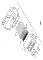
- the connector 10 includes a connector body 100, a retainer 110, a plurality of contacts 112, and a two-piece backshell 120.
- Each one of the plurality of contacts is configured to be connected to a corresponding wire. This can be done, for example, by crimping a proximal end of each contact around a corresponding wire, soldering a proximal end of each contact to a corresponding wire, etc.
- the plurality of contacts 112 are connected to a plurality of wires 114, each contact is inserted into a corresponding aperture in the retainer 110.
- the retainer 110 is then inserted into a proximal end of the connector body 100.
- the proximal end of the connector body 100 includes a cavity configured to receive at least a portion of the retainer, and the distal end of the connector body includes a plurality of apertures configured to receive at least a portion of the plurality of contacts.
- the backshell 120 is then connected to the connector body 100.
- the connector 10 is configured so that the step of placing (or pressing) the retainer 110 into the connector body 100 results in an application of pressure on the retainer 110, thereby resulting in increased friction between the, retainer and the plurality of contacts.
- the connector 10 is configured so that the step of connecting the backshell 120 to the connector body 100 results in an application of pressure on the retainer 110, thereby resulting in increased friction between the retainer and the plurality of contacts.
- the user-configurable connector is designed so that when the retainer is removed from the connector body, each contact is relatively easy to insert into and remove from the retainer (e.g ., a relatively low amount of friction exists between each contact and a corresponding aperture in the retainer). However, when the retainer is inserted into the connector body and/or the backshell is attached to the connector body, each connector becomes securely retained in the retainer.
- the connector In the first embodiment of the present invention, it becomes difficult (if not impossible) to insert a contact into, or remove a contact from the retainer when the retainer is inserted into the connector body. In the second embodiment of the present invention, it become difficult (if not impossible) to insert a contact into, or remove a contact from the retainer when the backshell is attached to the connector body. In either embodiment, or in a third embodiment, which is a combination of the two, assembling the connector results in a relatively high amount of friction between each contact and a corresponding aperture in the retainer.
- the present invention is not limited to the connector illustrated in Figure 1 .
- the present invention may be implemented in either a plug having a plurality of pins, or a receptacle having a plurality of sockets.
- the present invention is not limited to any particular type of retainer.
- a retainer manufactured out of any known pliable material e.g ., an elastomeric material, a thermo-plastic elastomeric material, etc.
- the present invention is not limited to the use of any particular type of backshell.
- any backshell (or backing structure) that can be connected to the connector body e.g ., using screws, a snap-fit connector, etc.
- results in the application of pressure on the retainer is considered to be within the spirit and scope of the present invention.
- the backshell 120 includes first and second portions (122, 124), wherein the first portion 122 includes a set of latches (not shown) and a first post 128a, and the second portion 124 includes a set of slots (126a, 126b) and a second post 128b.
- the backshell 120 can be connected to the connector body 100 by placing the first post 128a into a first hole 106a in the connector body 100, and by placing the second post 128b into a second hole 106b in the connector body 100.
- the first and second portions of the backshell (122, 124) can then be connected together by snap-fitting the set of latches (not shown) into the set of slots (126a, 126b). In one embodiment of the present invention, this results in the application (or further application) of pressure on the retainer 110, thereby securing the plurality of contacts in place. Further, by using a multi-portion backshell that includes at least one post, hole, latch and/or slot, the backshell can be attached to the connector body without the need for any tool, or at least any special tool.
- Figure 3 shows the user-configurable connector 10 fully assembled.
- the retainer 110 e.g ., elastomeric retainer
- the retainer 110 may also include a plurality of "fingers” 310 extending inward toward each contact.
- a plurality of "fingers” or a plurality of inwardly protruding, and spaced apart elements
- the features shown in Figures 2 and 3 are merely exemplary, and are not limitations of the present invention.
- a backshell that includes one or more portions, and any suitable structure for affixing the backshell to the connector body, is within the spirit and scope of the present invention.
- the user-configured connector can then be connected to a corresponding connector (e.g ., a corresponding plug, a corresponding receptacle, etc.).
- a corresponding connector e.g ., a corresponding plug, a corresponding receptacle, etc.
- screws are generally used to hold (or secure) connectors together, there are drawbacks to using screws. For example, it takes tools (e.g ., a screwdriver, etc.) and a certain amount of time to insert and remove a screw. By way of another example, screws can be dropped during installation/removal, which can result in damage to the connectors ( e.g ., when they are being connected together).
- a latching mechanism e.g ., a T-shaped latch
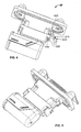
- a first end of the T-latch 400 includes a pivot 440 for pivotally connecting the T-latch 400 to the first connector 40
- a second end of the T-latch 400 includes a dentent 410.
- the pair of deflectable fingers 420 includes an indented inner portion 430 adapted to receive the dentent 410.
- the deflectable fingers 420 will temporarily spread apart, allowing the dentent 410 to move into the indented inner portion 430. With the dentent 410 in place, the deflectable fingers 420 will spring back to their initial position, thereby preventing the T-latch from moving away from the second connector 10. This can be seen, for example, in Figure 5 . It should be appreciated that the present invention is not limited to the T-latch shown in Figures 4 and 5 .
- any latch that is pivotally connected to a first connector and can be snap-fitted into a receiving device on a second connector is within the spirit and scope of the present invention.
- the snap-fitting may include, for example, one or more dentents (e.g ., a first dentent on a first side of the latch and second dentent on a second and opposite side of the latch), or the like, and one or more indented inner portions, or the like.
- a lanyard mechanism that does not include any screws can be used to secure first and second connectors together.
- Figure 6 shows a lanyard mechanism 600 in accordance with one embodiment of the present invention.
- a connector 10 includes a first dovetail 620
- a second connector 40 includes a second dovetail 610
- the lanyard mechanism 600 includes a slot 630 and a latch 640, wherein the slot 630 is configured to mate with the first dovetail 620, and the latch 640 is configured to hook over the second dovetail 610.
- the lanyard mechanism 600 which includes a first (or right) portion, a second (or left) portion substantially parallel to the first portion, and a third (or handle) portion connecting the first and second portions, can be affixed to the first connector 10 by mating the first slot 630 with the first dovetail 620.
- the latch 640 of the second connector 40 hooks (or snap-fits) over the second dovetail 610 on the second connector 40.
- the hook 640 In order to disconnect the first connector 10 from the second connector 40, the hook 640 must first be removed (or separated) from the second dovetail 610. This can be done, for example, by pulling on the handle portion ( i.e ., the lanyard) of the lanyard mechanism 600, thereby moving the hook 640 away from the second connector 40, and away from the second dovetail 610.
- the first and second dovetails are similar in shape and size, allowing the lanyard to be affixed to either the first or second connector.
- the slot 630 in the lanyard mechanism 600 is configured to mate with both the first and second dovetails (610, 620). By doing this, the lanyard becomes reversible, and can be affixed to ether the first connector 10 or the second connector 40, as desired by the user, or required by the application. It should be appreciated, however, that the present invention is not limited to any particular type of lanyard mechanism, or to the lanyard mechanism shown in Figure 6 .
- a connector that includes a differently shaped lanyard mechanism, additional dovetails (e.g ., dovetails on both sides of each connector, etc.), and/or additional slots (e.g ., slots on both the first and second portions of the lanyard mechanism, etc.), is within the spirit and scope of the present invention.
- additional dovetails e.g ., dovetails on both sides of each connector, etc.
- additional slots e.g ., slots on both the first and second portions of the lanyard mechanism, etc.
- the connector can be customized by the user so that it only mates with a similarly configured connector.
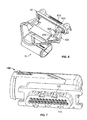
- a connector can be seen, for example, in Figure 7 .
- the connector body 100 includes a plurality of keyways (e.g ., 710), wherein each keyway is configured to receive a key ( e.g ., 720). See also Fig. 1 at 102 and 104.
- a pair of connectors e.g ., a connector and a corresponding connector
- this can be accomplished by inserting a key in at least one keyway on the connector, and remove the key (or ensure that there is no key) in the corresponding keyway on the corresponding connector.
- the connector in Figure 7 includes five keyways: two on top and three on bottom. As shown in Figure 7 , keys are inserted into the two keyways on top of the connector body 100, and one keyway on the bottom-left of the connector body 100.
- the connector can be configured to mate with a corresponding, and similarly configured connector (e.g ., one having no keys in the keyways on the top of the corresponding connector, and in the bottom-right keyway of the corresponding connector ( i.e ., the keyway in the corresponding connector that mirrors the bottom-left keyway of the connector)).
- a corresponding, and similarly configured connector e.g ., one having no keys in the keyways on the top of the corresponding connector, and in the bottom-right keyway of the corresponding connector ( i.e ., the keyway in the corresponding connector that mirrors the bottom-left keyway of the connector).
- the user can configure the connector so that it only mates with corresponding, and similarly configured connector.
- FIG. 8 illustrates one method of assembling a user-configurable connector and mating the connector with a corresponding connector, in accordance with one embodiment of the present invention.
- at least one contact e.g ., a pin, socket. etc.
- a proximal end of each contact may include a crimp barrel, a solder socket, etc.
- each contact is inserted into an aperture in an elastomeric retainer.
- the elastomeric retainer is then inserted into a connector body at step 806, and a backshell is attached to the connector body at step 808.
- the insertion of the elastomeric retainer results in an application of pressure on the elastomeric retainer, which further results in increased friction between the elastomeric retainer and the contact(s) included therein.
- the attachment of the backshell to the connector body results in an application of pressure on the elastomeric retainer, which further results in increased friction between the elastomeric retainer and the contact(s) included therein.
- at least one key is placed in at least one keyway on a distal end of the connector body, resulting in a user-programmable connector. The connector is then mated with a corresponding connector that is similarly configured.
- the connector is then secured to the corresponding connector by either snap-fitting a latch (e.g ., a T-latch, etc.) into a corresponding indented inner portion, or snap-fitting a lanyard latch over a corresponding dovetail, ending the method at step 816.
- a latch e.g ., a T-latch, etc.
- snap-fitting a lanyard latch over a corresponding dovetail ending the method at step 816.
- the foregoing steps do not need to be performed in the order presented in Figure 8 .
- the step of inserting keys can be performed before the contact is connected to wire, before the elastomeric retainer is inserted into the connector body, or before the backshell is secured to the connector body.
Landscapes
- Engineering & Computer Science (AREA)
- Manufacturing & Machinery (AREA)
- Connector Housings Or Holding Contact Members (AREA)
- Details Of Connecting Devices For Male And Female Coupling (AREA)
Applications Claiming Priority (1)
| Application Number | Priority Date | Filing Date | Title |
|---|---|---|---|
| US13/740,676 US8790129B1 (en) | 2013-01-14 | 2013-01-14 | User configurable connector |
Publications (3)
| Publication Number | Publication Date |
|---|---|
| EP2755283A2 true EP2755283A2 (de) | 2014-07-16 |
| EP2755283A3 EP2755283A3 (de) | 2014-08-06 |
| EP2755283B1 EP2755283B1 (de) | 2020-03-18 |
Family
ID=48655993
Family Applications (1)
| Application Number | Title | Priority Date | Filing Date |
|---|---|---|---|
| EP13173164.8A Active EP2755283B1 (de) | 2013-01-14 | 2013-06-21 | Benutzerkonfigurierbarer Stecker |
Country Status (6)
| Country | Link |
|---|---|
| US (1) | US8790129B1 (de) |
| EP (1) | EP2755283B1 (de) |
| BR (1) | BR112015016864A2 (de) |
| CA (1) | CA2897317C (de) |
| MX (1) | MX348610B (de) |
| WO (1) | WO2014110333A1 (de) |
Cited By (4)
| Publication number | Priority date | Publication date | Assignee | Title |
|---|---|---|---|---|
| CN112310699A (zh) * | 2019-07-29 | 2021-02-02 | 泰连公司 | 插头连接器 |
| TWI750343B (zh) * | 2017-04-14 | 2021-12-21 | 日商太谷電子日本合同公司 | 電連接器 |
| TWI755092B (zh) * | 2020-10-12 | 2022-02-11 | 貿聯國際股份有限公司 | 電子線材的線端連接組件 |
| US12516822B1 (en) * | 2021-04-21 | 2026-01-06 | Hti Technology And Industries, Inc. | Long-bar latch with enhanced serviceability features |
Families Citing this family (7)
| Publication number | Priority date | Publication date | Assignee | Title |
|---|---|---|---|---|
| US9735491B2 (en) * | 2015-07-15 | 2017-08-15 | Dynomax Inc. | Easily removable contacts for micro connectors |
| CN106856278B (zh) * | 2016-04-18 | 2019-09-03 | 凡甲电子(苏州)有限公司 | 电连接器 |
| US10333241B2 (en) * | 2016-07-12 | 2019-06-25 | Dynomax Inc. | Easily removable contacts for micro connectors |
| JP6840583B2 (ja) * | 2017-03-16 | 2021-03-10 | モレックス エルエルシー | コネクタアッセンブリ及びコネクタカバー |
| JP7268083B2 (ja) * | 2021-05-13 | 2023-05-02 | 矢崎総業株式会社 | プロテクタ、および、ワイヤハーネス |
| JP1703911S (de) * | 2021-06-08 | 2022-01-04 | ||
| JP1703913S (de) * | 2021-06-08 | 2022-01-04 |
Family Cites Families (17)
| Publication number | Priority date | Publication date | Assignee | Title |
|---|---|---|---|---|
| US2563762A (en) * | 1946-02-11 | 1951-08-07 | Bendix Aviat Corp | Electrical connector having resilient insert |
| BE757099A (fr) * | 1969-10-15 | 1971-03-16 | Bunker Ramo | Connecteur electrique |
| GB1362265A (en) | 1971-03-12 | 1974-08-07 | Cannon Electric Great Britain | Electrical connectors |
| US3905672A (en) | 1974-05-28 | 1975-09-16 | Itt | Sealed electrical connector |
| CA1124347A (en) * | 1979-05-21 | 1982-05-25 | Willem F. Bakker | Connector assembly for electrical conduit |
| GB2166605A (en) * | 1984-11-07 | 1986-05-08 | Plessey Co Plc | Improvements relating to contact retention arrangements |
| US4946402A (en) | 1989-10-19 | 1990-08-07 | General Motors Corporation | Electrical connector with improved sealing arrangement |
| US5711685A (en) | 1996-01-23 | 1998-01-27 | Tescorp Seismic Products, Inc. | Electrical connector having removable seal at cable entry end |
| US5762520A (en) | 1996-04-30 | 1998-06-09 | The Whitaker Corporation | Hermaphroditic wire cover |
| EP0984523B1 (de) * | 1998-08-31 | 2003-01-22 | The Whitaker Corporation | Elektrischer Verbinder mit Kappe |
| ES1044321Y (es) * | 1999-08-03 | 2000-09-01 | Mecanismos Aux Ind | Conjunto conector electrico. |
| JP2001143812A (ja) | 1999-11-17 | 2001-05-25 | Sumitomo Wiring Syst Ltd | カバー付きコネクタ |
| JP2002042973A (ja) * | 2000-06-30 | 2002-02-08 | Three M Innovative Properties Co | コネクタの符号キー構造、該キー構造を有するコネクタ、該キー構造に用いる符号キー形成素子、及び符号キー形成部材 |
| JP4520315B2 (ja) * | 2005-01-21 | 2010-08-04 | タイコエレクトロニクスジャパン合同会社 | コネクタ用電線カバー |
| WO2009059440A1 (de) | 2007-11-07 | 2009-05-14 | Multi-Holding Ag | Stecker und steckverbindung für roboter |
| JP5150428B2 (ja) * | 2008-09-17 | 2013-02-20 | 矢崎総業株式会社 | コネクタ |
| JP5598384B2 (ja) * | 2011-03-04 | 2014-10-01 | 住友電装株式会社 | コネクタ |
-
2013
- 2013-01-14 US US13/740,676 patent/US8790129B1/en active Active
- 2013-06-21 EP EP13173164.8A patent/EP2755283B1/de active Active
-
2014
- 2014-01-10 MX MX2015008988A patent/MX348610B/es active IP Right Grant
- 2014-01-10 WO PCT/US2014/010990 patent/WO2014110333A1/en not_active Ceased
- 2014-01-10 CA CA2897317A patent/CA2897317C/en active Active
- 2014-01-10 BR BR112015016864A patent/BR112015016864A2/pt not_active Application Discontinuation
Non-Patent Citations (1)
| Title |
|---|
| None |
Cited By (5)
| Publication number | Priority date | Publication date | Assignee | Title |
|---|---|---|---|---|
| TWI750343B (zh) * | 2017-04-14 | 2021-12-21 | 日商太谷電子日本合同公司 | 電連接器 |
| CN112310699A (zh) * | 2019-07-29 | 2021-02-02 | 泰连公司 | 插头连接器 |
| CN112310699B (zh) * | 2019-07-29 | 2024-06-04 | 泰连公司 | 插头连接器 |
| TWI755092B (zh) * | 2020-10-12 | 2022-02-11 | 貿聯國際股份有限公司 | 電子線材的線端連接組件 |
| US12516822B1 (en) * | 2021-04-21 | 2026-01-06 | Hti Technology And Industries, Inc. | Long-bar latch with enhanced serviceability features |
Also Published As
| Publication number | Publication date |
|---|---|
| US20140199879A1 (en) | 2014-07-17 |
| MX2015008988A (es) | 2016-06-21 |
| EP2755283B1 (de) | 2020-03-18 |
| CA2897317A1 (en) | 2014-07-17 |
| EP2755283A3 (de) | 2014-08-06 |
| CA2897317C (en) | 2019-10-08 |
| US8790129B1 (en) | 2014-07-29 |
| MX348610B (es) | 2017-06-21 |
| WO2014110333A1 (en) | 2014-07-17 |
| BR112015016864A2 (pt) | 2017-07-11 |
Similar Documents
| Publication | Publication Date | Title |
|---|---|---|
| CA2897317C (en) | User configurable connector | |
| US11539162B2 (en) | Magnetic latching connector | |
| EP2087560B1 (de) | Zirkuläres miniatursteckersystem | |
| CN101689721B (zh) | 用于电连接器的触头 | |
| EP0182641A2 (de) | Zugentlastungsvorrichtung für elektrische Verbinder | |
| EP3384564B1 (de) | Elektrischer einwegsteckverbinder mit einer leiterplatte | |
| CN104145375A (zh) | 具有推入式触头的电连接器 | |
| US7077708B1 (en) | Connector assembly | |
| JP2016524300A (ja) | 複数のプラグインコネクタを備えるシステムおよび多重プラグインコネクタ | |
| EP0788196A2 (de) | Stecker und Buchse | |
| US7604518B2 (en) | Electrical contact with retention latch | |
| CN100487985C (zh) | 电路板和插座组件 | |
| US4170393A (en) | Electrical connector with replaceable contacts | |
| US6722922B2 (en) | Heavy duty electrical connector | |
| JPH034467A (ja) | 防水型電気コネクタアセンブリ | |
| US11424576B2 (en) | Retention devices | |
| CN103843200A (zh) | 电连接器系统及制作该系统的方法 | |
| US20110014810A1 (en) | Connector frame | |
| JP2001357944A (ja) | プラグコネクタ | |
| US20020182924A1 (en) | Connector for electronic appliance | |
| EP1571733B1 (de) | Elektrischer Verbinder | |
| CN211377081U (zh) | 一种具有多重防呆结构的连接器 | |
| US7255608B2 (en) | Connector assembly and method having segmented body portion | |
| US12444880B2 (en) | Magnetic power distribution assembly | |
| KR101159730B1 (ko) | 방수핀 삽입이 용이한 커넥터 조립체 |
Legal Events
| Date | Code | Title | Description |
|---|---|---|---|
| PUAL | Search report despatched |
Free format text: ORIGINAL CODE: 0009013 |
|
| PUAI | Public reference made under article 153(3) epc to a published international application that has entered the european phase |
Free format text: ORIGINAL CODE: 0009012 |
|
| 17P | Request for examination filed |
Effective date: 20130621 |
|
| AK | Designated contracting states |
Kind code of ref document: A2 Designated state(s): AL AT BE BG CH CY CZ DE DK EE ES FI FR GB GR HR HU IE IS IT LI LT LU LV MC MK MT NL NO PL PT RO RS SE SI SK SM TR |
|
| AX | Request for extension of the european patent |
Extension state: BA ME |
|
| AK | Designated contracting states |
Kind code of ref document: A3 Designated state(s): AL AT BE BG CH CY CZ DE DK EE ES FI FR GB GR HR HU IE IS IT LI LT LU LV MC MK MT NL NO PL PT RO RS SE SI SK SM TR |
|
| AX | Request for extension of the european patent |
Extension state: BA ME |
|
| RIC1 | Information provided on ipc code assigned before grant |
Ipc: H01R 13/422 20060101AFI20140630BHEP Ipc: H01R 13/645 20060101ALI20140630BHEP Ipc: H01R 13/424 20060101ALI20140630BHEP Ipc: H01R 13/436 20060101ALI20140630BHEP Ipc: H01R 13/627 20060101ALI20140630BHEP Ipc: H01R 13/52 20060101ALI20140630BHEP |
|
| R17P | Request for examination filed (corrected) |
Effective date: 20150121 |
|
| RBV | Designated contracting states (corrected) |
Designated state(s): AL AT BE BG CH CY CZ DE DK EE ES FI FR GB GR HR HU IE IS IT LI LT LU LV MC MK MT NL NO PL PT RO RS SE SI SK SM TR |
|
| STAA | Information on the status of an ep patent application or granted ep patent |
Free format text: STATUS: EXAMINATION IS IN PROGRESS |
|
| 17Q | First examination report despatched |
Effective date: 20161207 |
|
| REG | Reference to a national code |
Ref country code: DE Ref legal event code: R079 Ref document number: 602013066882 Country of ref document: DE Free format text: PREVIOUS MAIN CLASS: H01R0013422000 Ipc: H01R0013410000 |
|
| RIC1 | Information provided on ipc code assigned before grant |
Ipc: H01R 13/41 20060101AFI20190705BHEP Ipc: H01R 13/424 20060101ALI20190705BHEP Ipc: H01R 13/645 20060101ALI20190705BHEP Ipc: H01R 13/627 20060101ALI20190705BHEP Ipc: H01R 13/52 20060101ALI20190705BHEP |
|
| GRAP | Despatch of communication of intention to grant a patent |
Free format text: ORIGINAL CODE: EPIDOSNIGR1 |
|
| STAA | Information on the status of an ep patent application or granted ep patent |
Free format text: STATUS: GRANT OF PATENT IS INTENDED |
|
| INTG | Intention to grant announced |
Effective date: 20190913 |
|
| GRAS | Grant fee paid |
Free format text: ORIGINAL CODE: EPIDOSNIGR3 |
|
| GRAA | (expected) grant |
Free format text: ORIGINAL CODE: 0009210 |
|
| STAA | Information on the status of an ep patent application or granted ep patent |
Free format text: STATUS: THE PATENT HAS BEEN GRANTED |
|
| AK | Designated contracting states |
Kind code of ref document: B1 Designated state(s): AL AT BE BG CH CY CZ DE DK EE ES FI FR GB GR HR HU IE IS IT LI LT LU LV MC MK MT NL NO PL PT RO RS SE SI SK SM TR |
|
| REG | Reference to a national code |
Ref country code: GB Ref legal event code: FG4D |
|
| REG | Reference to a national code |
Ref country code: DE Ref legal event code: R096 Ref document number: 602013066882 Country of ref document: DE |
|
| REG | Reference to a national code |
Ref country code: AT Ref legal event code: REF Ref document number: 1247019 Country of ref document: AT Kind code of ref document: T Effective date: 20200415 Ref country code: IE Ref legal event code: FG4D |
|
| PG25 | Lapsed in a contracting state [announced via postgrant information from national office to epo] |
Ref country code: FI Free format text: LAPSE BECAUSE OF FAILURE TO SUBMIT A TRANSLATION OF THE DESCRIPTION OR TO PAY THE FEE WITHIN THE PRESCRIBED TIME-LIMIT Effective date: 20200318 Ref country code: NO Free format text: LAPSE BECAUSE OF FAILURE TO SUBMIT A TRANSLATION OF THE DESCRIPTION OR TO PAY THE FEE WITHIN THE PRESCRIBED TIME-LIMIT Effective date: 20200618 Ref country code: RS Free format text: LAPSE BECAUSE OF FAILURE TO SUBMIT A TRANSLATION OF THE DESCRIPTION OR TO PAY THE FEE WITHIN THE PRESCRIBED TIME-LIMIT Effective date: 20200318 |
|
| REG | Reference to a national code |
Ref country code: NL Ref legal event code: MP Effective date: 20200318 |
|
| PG25 | Lapsed in a contracting state [announced via postgrant information from national office to epo] |
Ref country code: GR Free format text: LAPSE BECAUSE OF FAILURE TO SUBMIT A TRANSLATION OF THE DESCRIPTION OR TO PAY THE FEE WITHIN THE PRESCRIBED TIME-LIMIT Effective date: 20200619 Ref country code: BG Free format text: LAPSE BECAUSE OF FAILURE TO SUBMIT A TRANSLATION OF THE DESCRIPTION OR TO PAY THE FEE WITHIN THE PRESCRIBED TIME-LIMIT Effective date: 20200618 Ref country code: HR Free format text: LAPSE BECAUSE OF FAILURE TO SUBMIT A TRANSLATION OF THE DESCRIPTION OR TO PAY THE FEE WITHIN THE PRESCRIBED TIME-LIMIT Effective date: 20200318 Ref country code: LV Free format text: LAPSE BECAUSE OF FAILURE TO SUBMIT A TRANSLATION OF THE DESCRIPTION OR TO PAY THE FEE WITHIN THE PRESCRIBED TIME-LIMIT Effective date: 20200318 Ref country code: SE Free format text: LAPSE BECAUSE OF FAILURE TO SUBMIT A TRANSLATION OF THE DESCRIPTION OR TO PAY THE FEE WITHIN THE PRESCRIBED TIME-LIMIT Effective date: 20200318 |
|
| REG | Reference to a national code |
Ref country code: LT Ref legal event code: MG4D |
|
| PG25 | Lapsed in a contracting state [announced via postgrant information from national office to epo] |
Ref country code: NL Free format text: LAPSE BECAUSE OF FAILURE TO SUBMIT A TRANSLATION OF THE DESCRIPTION OR TO PAY THE FEE WITHIN THE PRESCRIBED TIME-LIMIT Effective date: 20200318 |
|
| PG25 | Lapsed in a contracting state [announced via postgrant information from national office to epo] |
Ref country code: PT Free format text: LAPSE BECAUSE OF FAILURE TO SUBMIT A TRANSLATION OF THE DESCRIPTION OR TO PAY THE FEE WITHIN THE PRESCRIBED TIME-LIMIT Effective date: 20200812 Ref country code: LT Free format text: LAPSE BECAUSE OF FAILURE TO SUBMIT A TRANSLATION OF THE DESCRIPTION OR TO PAY THE FEE WITHIN THE PRESCRIBED TIME-LIMIT Effective date: 20200318 Ref country code: RO Free format text: LAPSE BECAUSE OF FAILURE TO SUBMIT A TRANSLATION OF THE DESCRIPTION OR TO PAY THE FEE WITHIN THE PRESCRIBED TIME-LIMIT Effective date: 20200318 Ref country code: CZ Free format text: LAPSE BECAUSE OF FAILURE TO SUBMIT A TRANSLATION OF THE DESCRIPTION OR TO PAY THE FEE WITHIN THE PRESCRIBED TIME-LIMIT Effective date: 20200318 Ref country code: SM Free format text: LAPSE BECAUSE OF FAILURE TO SUBMIT A TRANSLATION OF THE DESCRIPTION OR TO PAY THE FEE WITHIN THE PRESCRIBED TIME-LIMIT Effective date: 20200318 Ref country code: EE Free format text: LAPSE BECAUSE OF FAILURE TO SUBMIT A TRANSLATION OF THE DESCRIPTION OR TO PAY THE FEE WITHIN THE PRESCRIBED TIME-LIMIT Effective date: 20200318 Ref country code: IS Free format text: LAPSE BECAUSE OF FAILURE TO SUBMIT A TRANSLATION OF THE DESCRIPTION OR TO PAY THE FEE WITHIN THE PRESCRIBED TIME-LIMIT Effective date: 20200718 Ref country code: SK Free format text: LAPSE BECAUSE OF FAILURE TO SUBMIT A TRANSLATION OF THE DESCRIPTION OR TO PAY THE FEE WITHIN THE PRESCRIBED TIME-LIMIT Effective date: 20200318 |
|
| REG | Reference to a national code |
Ref country code: AT Ref legal event code: MK05 Ref document number: 1247019 Country of ref document: AT Kind code of ref document: T Effective date: 20200318 |
|
| REG | Reference to a national code |
Ref country code: DE Ref legal event code: R097 Ref document number: 602013066882 Country of ref document: DE |
|
| PLBE | No opposition filed within time limit |
Free format text: ORIGINAL CODE: 0009261 |
|
| STAA | Information on the status of an ep patent application or granted ep patent |
Free format text: STATUS: NO OPPOSITION FILED WITHIN TIME LIMIT |
|
| PG25 | Lapsed in a contracting state [announced via postgrant information from national office to epo] |
Ref country code: ES Free format text: LAPSE BECAUSE OF FAILURE TO SUBMIT A TRANSLATION OF THE DESCRIPTION OR TO PAY THE FEE WITHIN THE PRESCRIBED TIME-LIMIT Effective date: 20200318 Ref country code: MC Free format text: LAPSE BECAUSE OF FAILURE TO SUBMIT A TRANSLATION OF THE DESCRIPTION OR TO PAY THE FEE WITHIN THE PRESCRIBED TIME-LIMIT Effective date: 20200318 Ref country code: AT Free format text: LAPSE BECAUSE OF FAILURE TO SUBMIT A TRANSLATION OF THE DESCRIPTION OR TO PAY THE FEE WITHIN THE PRESCRIBED TIME-LIMIT Effective date: 20200318 Ref country code: DK Free format text: LAPSE BECAUSE OF FAILURE TO SUBMIT A TRANSLATION OF THE DESCRIPTION OR TO PAY THE FEE WITHIN THE PRESCRIBED TIME-LIMIT Effective date: 20200318 Ref country code: IT Free format text: LAPSE BECAUSE OF FAILURE TO SUBMIT A TRANSLATION OF THE DESCRIPTION OR TO PAY THE FEE WITHIN THE PRESCRIBED TIME-LIMIT Effective date: 20200318 |
|
| REG | Reference to a national code |
Ref country code: CH Ref legal event code: PL |
|
| 26N | No opposition filed |
Effective date: 20201221 |
|
| PG25 | Lapsed in a contracting state [announced via postgrant information from national office to epo] |
Ref country code: PL Free format text: LAPSE BECAUSE OF FAILURE TO SUBMIT A TRANSLATION OF THE DESCRIPTION OR TO PAY THE FEE WITHIN THE PRESCRIBED TIME-LIMIT Effective date: 20200318 |
|
| PG25 | Lapsed in a contracting state [announced via postgrant information from national office to epo] |
Ref country code: LU Free format text: LAPSE BECAUSE OF NON-PAYMENT OF DUE FEES Effective date: 20200621 |
|
| REG | Reference to a national code |
Ref country code: BE Ref legal event code: MM Effective date: 20200630 |
|
| PG25 | Lapsed in a contracting state [announced via postgrant information from national office to epo] |
Ref country code: IE Free format text: LAPSE BECAUSE OF NON-PAYMENT OF DUE FEES Effective date: 20200621 Ref country code: LI Free format text: LAPSE BECAUSE OF NON-PAYMENT OF DUE FEES Effective date: 20200630 Ref country code: CH Free format text: LAPSE BECAUSE OF NON-PAYMENT OF DUE FEES Effective date: 20200630 |
|
| PG25 | Lapsed in a contracting state [announced via postgrant information from national office to epo] |
Ref country code: BE Free format text: LAPSE BECAUSE OF NON-PAYMENT OF DUE FEES Effective date: 20200630 Ref country code: SI Free format text: LAPSE BECAUSE OF FAILURE TO SUBMIT A TRANSLATION OF THE DESCRIPTION OR TO PAY THE FEE WITHIN THE PRESCRIBED TIME-LIMIT Effective date: 20200318 |
|
| PG25 | Lapsed in a contracting state [announced via postgrant information from national office to epo] |
Ref country code: TR Free format text: LAPSE BECAUSE OF FAILURE TO SUBMIT A TRANSLATION OF THE DESCRIPTION OR TO PAY THE FEE WITHIN THE PRESCRIBED TIME-LIMIT Effective date: 20200318 Ref country code: MT Free format text: LAPSE BECAUSE OF FAILURE TO SUBMIT A TRANSLATION OF THE DESCRIPTION OR TO PAY THE FEE WITHIN THE PRESCRIBED TIME-LIMIT Effective date: 20200318 Ref country code: CY Free format text: LAPSE BECAUSE OF FAILURE TO SUBMIT A TRANSLATION OF THE DESCRIPTION OR TO PAY THE FEE WITHIN THE PRESCRIBED TIME-LIMIT Effective date: 20200318 |
|
| PG25 | Lapsed in a contracting state [announced via postgrant information from national office to epo] |
Ref country code: MK Free format text: LAPSE BECAUSE OF FAILURE TO SUBMIT A TRANSLATION OF THE DESCRIPTION OR TO PAY THE FEE WITHIN THE PRESCRIBED TIME-LIMIT Effective date: 20200318 Ref country code: AL Free format text: LAPSE BECAUSE OF FAILURE TO SUBMIT A TRANSLATION OF THE DESCRIPTION OR TO PAY THE FEE WITHIN THE PRESCRIBED TIME-LIMIT Effective date: 20200318 |
|
| PGFP | Annual fee paid to national office [announced via postgrant information from national office to epo] |
Ref country code: DE Payment date: 20250402 Year of fee payment: 13 |
|
| PGFP | Annual fee paid to national office [announced via postgrant information from national office to epo] |
Ref country code: GB Payment date: 20250401 Year of fee payment: 13 |
|
| PGFP | Annual fee paid to national office [announced via postgrant information from national office to epo] |
Ref country code: FR Payment date: 20250409 Year of fee payment: 13 |