EP2755580B1 - Configuration de trou de verrouillage pour clou intramédullaire - Google Patents
Configuration de trou de verrouillage pour clou intramédullaire Download PDFInfo
- Publication number
- EP2755580B1 EP2755580B1 EP11761010.5A EP11761010A EP2755580B1 EP 2755580 B1 EP2755580 B1 EP 2755580B1 EP 11761010 A EP11761010 A EP 11761010A EP 2755580 B1 EP2755580 B1 EP 2755580B1
- Authority
- EP
- European Patent Office
- Prior art keywords
- hole
- intramedullary nail
- orientation
- driving end
- transponder
- Prior art date
- Legal status (The legal status is an assumption and is not a legal conclusion. Google has not performed a legal analysis and makes no representation as to the accuracy of the status listed.)
- Active
Links
Images

Classifications
-
- A—HUMAN NECESSITIES
- A61—MEDICAL OR VETERINARY SCIENCE; HYGIENE
- A61B—DIAGNOSIS; SURGERY; IDENTIFICATION
- A61B17/00—Surgical instruments, devices or methods
- A61B17/56—Surgical instruments or methods for treatment of bones or joints; Devices specially adapted therefor
- A61B17/58—Surgical instruments or methods for treatment of bones or joints; Devices specially adapted therefor for osteosynthesis, e.g. bone plates, screws or setting implements
- A61B17/68—Internal fixation devices, including fasteners and spinal fixators, even if a part thereof projects from the skin
- A61B17/72—Intramedullary devices, e.g. pins or nails
- A61B17/7233—Intramedullary devices, e.g. pins or nails with special means of locking the nail to the bone
-
- A—HUMAN NECESSITIES
- A61—MEDICAL OR VETERINARY SCIENCE; HYGIENE
- A61B—DIAGNOSIS; SURGERY; IDENTIFICATION
- A61B17/00—Surgical instruments, devices or methods
- A61B17/16—Instruments for performing osteoclasis; Drills or chisels for bones; Trepans
- A61B17/17—Guides or aligning means for drills, mills, pins or wires
- A61B17/1707—Guides or aligning means for drills, mills, pins or wires using electromagnetic effects, e.g. with magnet and external sensors
-
- A—HUMAN NECESSITIES
- A61—MEDICAL OR VETERINARY SCIENCE; HYGIENE
- A61B—DIAGNOSIS; SURGERY; IDENTIFICATION
- A61B17/00—Surgical instruments, devices or methods
- A61B17/16—Instruments for performing osteoclasis; Drills or chisels for bones; Trepans
- A61B17/17—Guides or aligning means for drills, mills, pins or wires
- A61B17/1725—Guides or aligning means for drills, mills, pins or wires for applying transverse screws or pins through intramedullary nails or pins
-
- A—HUMAN NECESSITIES
- A61—MEDICAL OR VETERINARY SCIENCE; HYGIENE
- A61B—DIAGNOSIS; SURGERY; IDENTIFICATION
- A61B17/00—Surgical instruments, devices or methods
- A61B17/56—Surgical instruments or methods for treatment of bones or joints; Devices specially adapted therefor
- A61B17/58—Surgical instruments or methods for treatment of bones or joints; Devices specially adapted therefor for osteosynthesis, e.g. bone plates, screws or setting implements
- A61B17/68—Internal fixation devices, including fasteners and spinal fixators, even if a part thereof projects from the skin
- A61B17/72—Intramedullary devices, e.g. pins or nails
-
- A—HUMAN NECESSITIES
- A61—MEDICAL OR VETERINARY SCIENCE; HYGIENE
- A61B—DIAGNOSIS; SURGERY; IDENTIFICATION
- A61B90/00—Instruments, implements or accessories specially adapted for surgery or diagnosis and not covered by any of the groups A61B1/00 - A61B50/00, e.g. for luxation treatment or for protecting wound edges
- A61B90/39—Markers, e.g. radio-opaque or breast lesions markers
-
- A—HUMAN NECESSITIES
- A61—MEDICAL OR VETERINARY SCIENCE; HYGIENE
- A61B—DIAGNOSIS; SURGERY; IDENTIFICATION
- A61B90/00—Instruments, implements or accessories specially adapted for surgery or diagnosis and not covered by any of the groups A61B1/00 - A61B50/00, e.g. for luxation treatment or for protecting wound edges
- A61B90/39—Markers, e.g. radio-opaque or breast lesions markers
- A61B2090/397—Markers, e.g. radio-opaque or breast lesions markers electromagnetic other than visible, e.g. microwave
-
- A—HUMAN NECESSITIES
- A61—MEDICAL OR VETERINARY SCIENCE; HYGIENE
- A61B—DIAGNOSIS; SURGERY; IDENTIFICATION
- A61B5/00—Measuring for diagnostic purposes; Identification of persons
- A61B5/06—Devices, other than using radiation, for detecting or locating foreign bodies ; Determining position of diagnostic devices within or on the body of the patient
Definitions
- the invention generally relates to an intramedullary nail.
- the invention relates to a locking hole arrangement provided at a non-driving end portion of an intramedullary nail, wherein this end portion of the nail is adapted to be positioned at a distal end portion of a humerus or a tibia, or at a proximal or at a distal end portion of a femur.
- the proximal end of the bone is the end of the bone being oriented toward the heart of the human body.
- the distal end of the bone is the end of the bone being oriented away from the heart of the human body.
- An intramedullary nail may be a femur nail, a humerus nail or a tibia nail, wherein the intramedullary nail comprises a non-driving end and a driving end.
- the non-driving end is the end of the nail which firstly enters the intramedullary channel of a bone. Entering the bone from the proximal end of the bone is denoted as antegrade insertion. Entering the bone from the distal end of the bone is denoted as retrograde insertion.
- a nail adapted to be implanted from the proximal end of the tibia may be denoted as antegrade tibia nail
- a nail adapted to be implanted from the distal end of the femur may be denoted as retrograde femur nail
- a nail adapted to be implanted from the proximal end of the femur may be denoted as antegrade femur nail
- a nail adapted to be implanted from the proximal end of the humerus may be denoted as antegrade humerus nail.
- a different locking pattern of the non-driving end portion of an intramedullary nail exists for each one of different nails, e.g. humerus, tibia, femur nails. Locking of the non-driving end portion of an intramedullary nail is performed mostly freehand.
- US 6,547,791 B1 discloses a tibia nail for retrograde implantation, comprising a tube with a continuous longitudinal bore and including a first anchoring portion with several cross-bores at its non-driving end portion, an adjoining connecting portion, a shank and a second anchoring portion at its driving end portion.
- the arrangement of the cross-bores permits to fix several fragments at their positions in the region of the tibia plateau, i.e. at the proximal end portion of the tibia.
- WO 2010/028046 A1 discloses an intramedullary nail targeting device for detecting the precise location and position of an opening of a through bore in an intramedullary nail in a bone or similar object within a body of tissue.
- An intramedullary nail is described having three bores for receiving screws in the distal end section of the nail, with two bores having substantially the same orientation and the third hole being perpendicular thereto.
- all four openings have the same orientation.
- an intramedullary nail comprises a driving end portion and a non-driving end portion with a longitudinal axis.
- the non-driving end portion comprises a locking hole arrangement with four holes, i.e. a first hole, a second hole, a third hole, and a fourth hole.
- the four holes are arranged as a sequence from the non-driving end of the intramedullary nail in a direction to the driving end of the nail, with the first hole arranged closer to the non-driving end than the second hole, the second hole arranged closer to the non-driving end than the third hole, and the third hole arranged closer to the non-driving end than the fourth hole.
- the first hole and the fourth hole have a corresponding first orientation and the second hole and the third hole have a corresponding second orientation.
- the first orientation is a medio-lateral orientation and the second orientation is an anterior-posterior orientation.
- the medio-lateral orientation and the anterior-posterior orientation are substantially orthogonal with respect to each other.
- orthogonal may include in this context an angle between 80 and 100 degrees.
- orientation of the first and fourth holes of the locking hole arrangement at the non-driving end portion of the intramedullary nail may also be different to orthogonal relative to the orientation of the second and third holes, as long as this orientation is well defined and, thus, known.
- the orientation may be 60 degrees or may be 45 degrees.
- the first, second, third and fourth holes are respectively adapted for receiving a locking screw.
- Such an arrangement of locking holes may be particularly usable at a non-driving end portion of an antegrade humerus nail, an antegrade tibia nail, an antegrade femur nail as well as a retrograde femur nail.
- At least one of the first hole, the second hole, the third hole and the fourth hole is orthogonally oriented with respect to the longitudinal axis of the non-driving end portion.
- an orientation not orthogonally with respect to the longitudinal axis may be provided. It may be, that all holes are inclined in a same way relative to the longitudinal axis, but also that at least one hole is inclined in another way as the other ones.
- a distance between a centre axis of the first hole and the centre axis of the second hole corresponds to a distance between a centre axis of the third hole and a centre axis of the fourth hole.
- the distances from a non-driving end of the intramedullary nail to a respective centre axis of a hole may be as follows:
- a distance from the non-driving end to the centre axis of the second hole may be 9 to 49 mm, preferably 10 mm.
- a distance from the non-driving end to the centre axis of the third hole may be 24 to 64 mm, preferably 25 mm.
- a distance from the non-driving end to the centre axis of the fourth hole may be 29 to 69 mm, preferably 30 mm.
- the intramedullary nail comprises a fifth hole, wherein a transponder may be arranged in this fifth hole.
- the fifth hole may have the same orientation as the first hole and the fourth hole, and may be centred between the second hole and the third hole, as well as between the first hole and the fourth hole.
- the distance from the non-driving end of the intramedullary nail to the fifth hole may be 16.5 to 56.5 mm, preferably 17.5 mm.
- the five holes are equally spaced from each other.
- the transponder may be adapted for generating a signal with a first preferred radiation direction in which the signal has specific symmetry characteristics, allowing the determination of the orientation of the first preferred radiation direction.
- the signal symmetry characteristics may be the characteristics of a dipole.
- the first preferred direction may be the axis of the dipole.
- the dipole signal characteristics may be generated by a coil.
- the transponder may be adapted for generating a signal being indicative for determining at least one of a spatial position and spatial orientation of the transponder so as to allow determining a respective spatial position and spatial orientation of at least one of the first, second, third and fourth holes, based on a predetermined spatial position and spatial orientation of the respective hole with respect to the transponder.
- first preferred radiation direction may be aligned with the orientation, i.e. the centre axis of the fifth hole.
- a second preferred radiation direction may be orthogonal to the first preferred radiation direction.
- At least one of the first hole, the second hole, the third hole, the fourth hole and the fifth hole comprises a thread.
- a locking screw and alternatively a transponder may be reliably arranged and fixed within one of the holes.
- a combination of an intramedullary nail, as described above, with a targeting detector is provided, wherein the targeting detector is arranged to detect the signal generating by a transponder at the intramedullary nail.
- the targeting detector may further be arranged to detect the orientation of the transponder, wherein the detector is adapted for signalling the correspondence of the orientation of at least one of the first hole, the second hole, the third hole and the fourth hole on the one hand, and a targeting orientation on the other hand, based on a predetermined spatial position and a spatial orientation of the respective first hole, second hole, third hole and fourth hole with respect to the transponder.
- the targeting detector may be located at a tool for introducing a locking screw, helping a physician to localize the locking hole in the non-driving end portion of the intramedullary nail during a so-called freehand introduction of a locking screw.
- the targeting detector may be located at a targeting device having a coupling portion adapted to be coupled to the driving end portion of the intramedullary nail.
- the targeting device may further comprise a drilling gauge with a drilling axis, for easily introducing a locking screw into a respective locking hole in the non-driving end portion of the intramedullary nail.
- US 7,686,818 B2 relates to a locking nail and stereotaxic apparatus thereof. Furthermore, US 2008/0170473 A1 relates to a targeting system. These documents especially provide information concerning exemplary transponders and the use thereof.
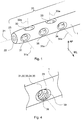
- Fig. 1 is an isometric view of a non-driving end portion 20 of an intramedullary nail 1.
- the non-driving end portion 20 includes a longitudinal axis 21, a non-driving end 22 and a longitudinal bore 23 arranged substantially parallel to the longitudinal axis 21.
- the non-driving end 22 is formed as a blunt end of the intramedullary nail 1. Furthermore, five holes are illustrated in Fig. 1 .
- the intramedullary nail 1 comprises a first hole 31 with a centre axis 31a, a second hole 32 with a centre axis 32a, a fifth hole 35 with a centre axis 35a, a third hole 33 with a centre axis 33a, and a fourth hole 34 with a centre axis 34a.
- the first hole 31, the fifth hole 35 and the fourth hole 34 are orientated in a first orientation
- the second hole 32 and the third hole 33 are orientated in a second orientation.
- Each of the centre axes of the holes is oriented orthogonal to the longitudinal axis 21. Furthermore, the first hole 31 and the fourth hole 34 are orientated orthogonal to the second hole 32 and the third hole 33.
- the fifth hole 35 is arranged in the middle between the first and fourth holes, orientated in the same direction as the first and fourth holes. The fifth hole 35 is adapted for receiving a transponder. Additionally, in Fig. 1 the directions medio-lateral ML and anterior-posterior AP are illustrated.
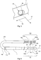
- Fig. 2 is a side view of the intramedullary nail in the medio-lateral direction.
- a transponder 50 may be arranged in the fifth hole, in the middle between the first hole 31 and the fourth hole 34.
- the visual part of the transponder has a greater diameter than the respective diameter of the first and fourth holes.
- Fig. 2 Further illustrated in Fig. 2 are the distances between some of the centre axes of the holes.
- the distance between the centre axis of the first hole 31 and the centre axis of the fourth hole 34 is indicated as d1.
- the distance between the centre axis of the first hole 31 and the centre axis 32a of the second hole 32, as well as the distance between the centre axis 33a of the third hole 33 and the centre axis of the fourth hole 34 is indicated as d2, that is, the distance between the centre axes of the first and second holes is equal to that of the third and fourth holes.
- the distance between the centre axis of the fourth hole 34 and the centre axis of the fifth hole with the transponder 50 is indicated as d1/2, that is, the transponder is arranged in the middle between the first and fourth holes.
- a driving end portion 10 of the intramedullary nails 1 is illustrated in fig. 2 . It is noted that the driving end portion 10 may have any shape or size, depending as to whether the intramedullary nail 1 should be used as humerus nail, as tibia nail or as femur nail.
- Fig. 3 is a section view of the non-driving end portion 20 along the plane A-A of Fig. 2 .
- the intramedullary nail 1 has a hollow shaft (due to the longitudinal bore 23) with a longitudinal axis 21 at its non-driving end portion 20.
- the first, fourth and fifth hole are illustrated parallel to each other and in a first orientation, within the plane of the figure, and the second and third holes are illustrated parallel to each other and in a second orientation, perpendicular to the plane of the figure.
- Fig. 4 is an isometric view showing, in detail, one of the holes 31, 32, 33, 34 and 35 of the non-driving end portion of the intramedullary nail 1.
- the hole in fig. 4 includes a thread 38 and a chamfer 39.
- the chamfer 39 may facilitate an introduction of a screw or of a transponder into the hole.
- the thread 38 may be provided in only one of or at least one of as well as in every one of the holes in the non-driving end portion of the intramedullary nail.
- the holes may also comprise only a chamfer 39 and no thread 38.
- Fig. 5 is a detailed view of the fifth hole 35 with a transponder 50 located within the fifth hole. Additionally, a first preferred radiation direction 51 of the transponder 50 and a second preferred radiation direction 52 of the transponder 50 are illustrated.
- the first preferred radiation direction 51 is substantially aligned with the centre axis of the fifth hole 35 and thus with the centre axis of the transponder 50.
- the second preferred radiation direction 52 is orientated orthogonal to the first preferred radiation direction 51. It is noted that the second preferred radiation direction may be within a plane being orthogonal to the first preferred radiation direction.
- Fig. 6 shows a combination of an intramedullary nail 1 together with a targeting device 100, wherein the targeting device 100 includes a portion 110 with a coupling portion 112, wherein the coupling portion 112 may be adapted to be coupled to the driving end portion 10 of the intramedullary nail 1. Furthermore, the targeting device 100 comprises a portion 120 including at least one drilling gauge 130 with a drilling axis 130a.
- the targeting device 100 is dimensioned so that the drilling axis of one of the drilling gauges 130 is aligned with, for example, the centre axis 33a of the third hole 33, and that the drilling axis of another one of the drilling gauges 130 is aligned with the centre axis 32a of the second hole 32.
- the targeting device 100 may further comprise a targeting detector 150 arranged in a known relation to the holes of the non-driving end portion of the intramedullary nail, so that the targeting detector 150 may receive signals from the transponder 50 to be able to indicate the relative position of the respective drilling gauge relative to one of the holes of the locking hole arrangement in the non-driving end portion 20 of the intramedullary nail 1.
- the targeting device 100 may also be orientated relative to the intramedullary nail so that drilling gauges may be aligned with the first or the fourth hole in the intramedullary nail.
Landscapes
- Health & Medical Sciences (AREA)
- Life Sciences & Earth Sciences (AREA)
- Surgery (AREA)
- Orthopedic Medicine & Surgery (AREA)
- Biomedical Technology (AREA)
- Molecular Biology (AREA)
- Nuclear Medicine, Radiotherapy & Molecular Imaging (AREA)
- Veterinary Medicine (AREA)
- Public Health (AREA)
- Engineering & Computer Science (AREA)
- General Health & Medical Sciences (AREA)
- Heart & Thoracic Surgery (AREA)
- Medical Informatics (AREA)
- Animal Behavior & Ethology (AREA)
- Oral & Maxillofacial Surgery (AREA)
- Dentistry (AREA)
- Neurology (AREA)
- Physics & Mathematics (AREA)
- Electromagnetism (AREA)
- Pathology (AREA)
- Surgical Instruments (AREA)
Claims (15)
- Clou intramédullaire, comportant :une partie d'extrémité entraînante (10), etune partie d'extrémité non entraînante (20) ayant un axe longitudinal (21),dans lequel la partie d'extrémité non entraînante comporte un agencement à trous de blocage ayant un premier trou (31), un deuxième trou (32), un troisième trou (33) et un quatrième trou (34),dans lequel le premier trou est agencé plus près d'une extrémité non entraînante (22) du clou intramédullaire que le deuxième trou, le deuxième trou est agencé plus près de l'extrémité non entraînante que le troisième trou, et le troisième trou est agencé plus près de l'extrémité non entraînante que le quatrième trou,dans lequel le premier trou et le quatrième trou ont une première orientation correspondante, caractérisé en ce que le deuxième trou et le troisième trou ont une seconde orientation correspondante,dans lequel une distance (d2) entre un axe central (31a) du premier trou (31) et un axe central (32a) du deuxième trou (32) correspond à une distance (d2) entre un axe central (33a) du troisième trou (33) et un axe central (34a) du quatrième trou (34).
- Clou intramédullaire selon la revendication 1, dans lequel la première orientation est une orientation médio-latérale (ML) et la seconde orientation est une orientation antérieure-postérieure (AP).
- Clou intramédullaire selon l'une quelconque des revendications 1 à 2, dans lequel la distance entre une extrémité non entraînante (22) du clou intramédullaire (1) et :l'axe central (31a) du premier trou (31) est de 4 à 44 mm, de préférence 5 mm,l'axe central (32a) du deuxième trou (32) est de 9 à 49 mm, de préférence 10 mm,l'axe central (33a) du troisième trou (33) est de 24 à 64 mm, de préférence 25 mm, etl'axe central (34a) du quatrième trou (34) est de 29 à 69 mm, de préférence 30 mm.
- Clou intramédullaire selon l'une quelconque des revendications 1 à 3, comportant en outre un cinquième trou (35).
- Clou intramédullaire selon l'une quelconque des revendications 1 à 4, dans lequel au moins l'un des premier (31), deuxième (32), troisième (33), quatrième (34) et cinquième (35) trous comporte un filetage (38).
- Clou intramédullaire selon la revendication 4 ou 5, dans lequel le cinquième trou (35) a la même orientation que le premier trou (31) et le quatrième trou (34), et est agencé à mi-chemin entre le deuxième trou (32) et le troisième trou (33).
- Clou intramédullaire selon l'une quelconque des revendications 4 à 6, dans lequel la distance entre l'extrémité non entraînante (22) du clou intramédullaire (1) et le cinquième trou (35) est de 16,5 à 56,5 mm, de préférence 17,5 mm.
- Clou intramédullaire selon l'une quelconque des revendications 1 à 7, comportant en outre un transpondeur (50).
- Clou intramédullaire selon la revendication 8, dans lequel le transpondeur (50) est agencé dans le cinquième trou (35).
- Clou intramédullaire selon l'une quelconque des revendications 8 et 9, dans lequel le transpondeur (50) est adapté pour générer un signal, dans lequel le transpondeur a une première direction de rayonnement préférée (51), première direction de rayonnement préférée dans laquelle le signal a des caractéristiques de symétrie spécifiques, permettant de déterminer l'orientation de la première direction de rayonnement préférée.
- Clou intramédullaire selon l'une quelconque des revendications 8 à 10, dans lequel le transpondeur (50) est adapté pour générer un signal indicatif pour déterminer au moins un élément parmi une position spatiale et une orientation spatiale du transpondeur de manière à permettre la détermination d'une position spatiale et d'une orientation spatiale respectives d'au moins un trou parmi le premier trou (31), le deuxième trou (32), le troisième trou (33) et le quatrième trou (34) sur la base d'une position spatiale et d'une orientation spatiale prédéterminées des premier, deuxième, troisième et quatrième trous respectifs par rapport au transpondeur.
- Clou intramédullaire selon l'une quelconque des revendications 10 et 11, dans lequel la première direction de rayonnement préférée (51) est alignée sur l'orientation du cinquième trou (35).
- Combinaison d'un clou intramédullaire selon l'une quelconque des revendications 8 à 12 et un détecteur de ciblage (150), dans laquelle le détecteur de ciblage est conçu pour détecter le signal généré par le transpondeur (50).
- Combinaison selon la revendication 13, dans laquelle le détecteur de ciblage est adapté pour être temporairement fixé au clou intramédullaire (1) via un dispositif de couplage (100).
- Combinaison selon l'une quelconque des revendications 13 et 14, dans laquelle le détecteur est conçu pour détecter l'orientation du transpondeur (50), dans laquelle le détecteur est adapté pour signaler la correspondance de l'orientation du au moins un trou parmi le premier trou (31), le deuxième trou (32), le troisième trou (33) et le quatrième trou (34) d'une part et une orientation de ciblage (130a) d'autre part, sur la base d'une position spatiale et d'une orientation spatiale prédéterminées des premier, deuxième, troisième et quatrième trous respectifs par rapport au transpondeur.
Applications Claiming Priority (1)
| Application Number | Priority Date | Filing Date | Title |
|---|---|---|---|
| PCT/EP2011/004657 WO2013037386A1 (fr) | 2011-09-16 | 2011-09-16 | Configuration de trou de verrouillage pour clou intramédullaire |
Publications (2)
| Publication Number | Publication Date |
|---|---|
| EP2755580A1 EP2755580A1 (fr) | 2014-07-23 |
| EP2755580B1 true EP2755580B1 (fr) | 2016-06-22 |
Family
ID=44677843
Family Applications (1)
| Application Number | Title | Priority Date | Filing Date |
|---|---|---|---|
| EP11761010.5A Active EP2755580B1 (fr) | 2011-09-16 | 2011-09-16 | Configuration de trou de verrouillage pour clou intramédullaire |
Country Status (8)
| Country | Link |
|---|---|
| US (1) | US9408645B2 (fr) |
| EP (1) | EP2755580B1 (fr) |
| JP (1) | JP5980333B2 (fr) |
| CN (1) | CN103796599B (fr) |
| AU (1) | AU2011376744B2 (fr) |
| CA (1) | CA2847599C (fr) |
| ES (1) | ES2587762T3 (fr) |
| WO (1) | WO2013037386A1 (fr) |
Cited By (2)
| Publication number | Priority date | Publication date | Assignee | Title |
|---|---|---|---|---|
| US11446072B2 (en) | 2017-10-10 | 2022-09-20 | DePuy Synthes Products, Inc. | Self-retaining nail to insertion handle interface |
| US12004785B2 (en) | 2022-04-21 | 2024-06-11 | DePuy Synthes Products, Inc. | Retrograde femoral intramedullary nail, and related systems and methods |
Families Citing this family (11)
| Publication number | Priority date | Publication date | Assignee | Title |
|---|---|---|---|---|
| US9220514B2 (en) | 2008-02-28 | 2015-12-29 | Smith & Nephew, Inc. | System and method for identifying a landmark |
| US9031637B2 (en) | 2009-04-27 | 2015-05-12 | Smith & Nephew, Inc. | Targeting an orthopaedic implant landmark |
| US8945147B2 (en) | 2009-04-27 | 2015-02-03 | Smith & Nephew, Inc. | System and method for identifying a landmark |
| WO2012154496A2 (fr) * | 2011-05-06 | 2012-11-15 | Smith & Nephew, Inc. | Ciblage de points de repère de dispositifs orthopédiques |
| US9895177B2 (en) * | 2016-01-15 | 2018-02-20 | ARTHREX, GmbH | Bone fixation device for treatment of femoral fractures |
| US10492803B2 (en) * | 2016-09-22 | 2019-12-03 | Globus Medical, Inc. | Systems and methods for intramedullary nail implantation |
| US11083503B2 (en) | 2016-09-22 | 2021-08-10 | Globus Medical, Inc. | Systems and methods for intramedullary nail implantation |
| CN106618710A (zh) * | 2017-02-20 | 2017-05-10 | 广东工业大学 | 一种与股骨骨髓腔形态相匹配的近端固定髓内钉 |
| US11633219B2 (en) | 2019-06-26 | 2023-04-25 | Globus Medical, Inc. | Fenestrated pedicle nail |
| CN113262031B (zh) * | 2021-06-28 | 2023-03-24 | 宁波兆盈医疗器械有限公司 | 一种胫骨髓内钉远端孔瞄准检具及其使用方法 |
| WO2026075913A1 (fr) * | 2024-10-02 | 2026-04-09 | Zimmer, Inc. | Groupe de vis distales pour clou tibial intramédullaire |
Citations (1)
| Publication number | Priority date | Publication date | Assignee | Title |
|---|---|---|---|---|
| US20090062796A1 (en) * | 2006-05-10 | 2009-03-05 | Concepts In Medicine, Llc | Modular, blade-rod, intramedullary fixation device |
Family Cites Families (30)
| Publication number | Priority date | Publication date | Assignee | Title |
|---|---|---|---|---|
| US4475545A (en) | 1982-12-06 | 1984-10-09 | Ender Hans G | Bone-nail |
| CH674613A5 (fr) | 1988-03-14 | 1990-06-29 | Synthes Ag | |
| US5127913A (en) * | 1991-04-22 | 1992-07-07 | Thomas Jr Charles B | Apparatus and method for implanting an intramedullary rod |
| CA2073266A1 (fr) | 1991-07-09 | 1993-01-10 | Stryker Corporation | Systeme de ciblage distal |
| US5411503A (en) | 1993-06-18 | 1995-05-02 | Hollstien; Steven B. | Instrumentation for distal targeting of locking screws in intramedullary nails |
| EP0706782B1 (fr) | 1994-10-14 | 1999-06-30 | Synthes AG, Chur | Appareil de fixation et/ou d'alignement longitudinal pour l'ostéosynthèse |
| US6270499B1 (en) | 1997-10-20 | 2001-08-07 | Synthes (U.S.A.) | Bone fixation device |
| EP0976365A1 (fr) | 1998-07-27 | 2000-02-02 | Osteo Ag | Clou tibial pour insertion rétrograde |
| US6120504A (en) | 1998-12-10 | 2000-09-19 | Biomet Inc. | Intramedullary nail having dual distal bore formation |
| DE50015249D1 (de) | 1999-05-12 | 2008-08-21 | Zimmer Gmbh | Verriegelungsnagel zur Versorgung von Femurschaftfrakturen |
| DE20012877U1 (de) | 2000-07-26 | 2001-12-06 | stryker Trauma GmbH, 24232 Schönkirchen | Verriegelungsnagel |
| DE20015775U1 (de) | 2000-09-12 | 2002-01-31 | stryker Trauma GmbH, 24232 Schönkirchen | Knochennagel |
| DE20204655U1 (de) | 2002-03-21 | 2002-06-13 | stryker Trauma GmbH, 24232 Schönkirchen | Verriegelungsnagel und Zielgerät |
| US7060075B2 (en) | 2002-07-18 | 2006-06-13 | Biosense, Inc. | Distal targeting of locking screws in intramedullary nails |
| DE20213166U1 (de) | 2002-08-28 | 2004-01-08 | Stryker Trauma Gmbh | Humerusnagel |
| WO2004028383A1 (fr) | 2002-09-27 | 2004-04-08 | Synthes Ag Chur | Clou centromedullaire |
| DE20300987U1 (de) | 2003-01-23 | 2003-04-10 | stryker Trauma GmbH, 24232 Schönkirchen | Implantat für die Osteosynthese |
| US6666670B1 (en) | 2003-05-22 | 2003-12-23 | Visteon Global Technologies, Inc. | Power steering pump |
| DE20314742U1 (de) | 2003-09-24 | 2003-12-04 | Stryker Trauma Gmbh | Zielgerät für einen Verriegelungsnagel sowie Verriegelungsnagel |
| CN1886097B (zh) | 2003-12-19 | 2010-04-28 | 斯恩蒂斯有限公司 | 髓内钉 |
| US7947043B2 (en) | 2004-01-20 | 2011-05-24 | Depuy Products, Inc. | Intramedullary nail and associated method |
| US7771428B2 (en) | 2004-06-11 | 2010-08-10 | Synthes Usa, Llc | Intramedullary rod with spiraling flutes |
| WO2006069453A1 (fr) * | 2004-12-31 | 2006-07-06 | Synthes Gmbh | Clou medullaire |
| DE202005009809U1 (de) | 2005-03-31 | 2005-08-25 | Stryker Trauma Gmbh | Datenübertragungssystem in Verbindung mit einem Implantat |
| CN101340851B (zh) | 2005-10-21 | 2012-12-12 | 精密医疗责任有限公司 | 具有锁定孔的矫形棒 |
| ES2315959T5 (es) | 2006-05-12 | 2016-05-26 | Stryker Trauma Gmbh | Dispositivo y sistema médico para la estimulación eléctrica de la osteogénesis |
| WO2008086501A2 (fr) * | 2007-01-11 | 2008-07-17 | Anthem Orthopaedics Llc | Dispositif de réparation osseuse intra-médullaire percutané et son procédé d'utilisation |
| CA2735131A1 (fr) * | 2008-09-02 | 2010-03-11 | Virginia Tech Intellectual Properties, Inc. | Dispositif de ciblage de clou intramedullaire |
| CA2777092C (fr) * | 2009-10-06 | 2019-12-03 | Northern Digital Inc. | Ciblage de points de repere de dispositifs orthopediques |
| BR112013005612A2 (pt) * | 2010-09-09 | 2016-05-03 | Synthes Gmbh | bastonete cirúrgico |
-
2011
- 2011-09-16 EP EP11761010.5A patent/EP2755580B1/fr active Active
- 2011-09-16 ES ES11761010.5T patent/ES2587762T3/es active Active
- 2011-09-16 AU AU2011376744A patent/AU2011376744B2/en not_active Ceased
- 2011-09-16 JP JP2014528870A patent/JP5980333B2/ja active Active
- 2011-09-16 CA CA2847599A patent/CA2847599C/fr not_active Expired - Fee Related
- 2011-09-16 CN CN201180073503.6A patent/CN103796599B/zh not_active Expired - Fee Related
- 2011-09-16 US US14/343,875 patent/US9408645B2/en active Active
- 2011-09-16 WO PCT/EP2011/004657 patent/WO2013037386A1/fr not_active Ceased
Patent Citations (1)
| Publication number | Priority date | Publication date | Assignee | Title |
|---|---|---|---|---|
| US20090062796A1 (en) * | 2006-05-10 | 2009-03-05 | Concepts In Medicine, Llc | Modular, blade-rod, intramedullary fixation device |
Cited By (3)
| Publication number | Priority date | Publication date | Assignee | Title |
|---|---|---|---|---|
| US11446072B2 (en) | 2017-10-10 | 2022-09-20 | DePuy Synthes Products, Inc. | Self-retaining nail to insertion handle interface |
| US12004785B2 (en) | 2022-04-21 | 2024-06-11 | DePuy Synthes Products, Inc. | Retrograde femoral intramedullary nail, and related systems and methods |
| US12458418B2 (en) | 2022-04-21 | 2025-11-04 | DePuy Synthes Products, Inc. | Retrograde femoral intramedullary nail, and related systems and methods |
Also Published As
| Publication number | Publication date |
|---|---|
| JP2014530646A (ja) | 2014-11-20 |
| JP5980333B2 (ja) | 2016-08-31 |
| WO2013037386A1 (fr) | 2013-03-21 |
| CA2847599A1 (fr) | 2013-03-21 |
| US20150080893A1 (en) | 2015-03-19 |
| EP2755580A1 (fr) | 2014-07-23 |
| CN103796599B (zh) | 2017-03-01 |
| ES2587762T3 (es) | 2016-10-26 |
| US9408645B2 (en) | 2016-08-09 |
| AU2011376744B2 (en) | 2015-03-26 |
| CA2847599C (fr) | 2016-09-06 |
| AU2011376744A1 (en) | 2014-03-13 |
| CN103796599A (zh) | 2014-05-14 |
Similar Documents
| Publication | Publication Date | Title |
|---|---|---|
| EP2755580B1 (fr) | Configuration de trou de verrouillage pour clou intramédullaire | |
| CN107582129B (zh) | 骨科植入物 | |
| US8920422B2 (en) | Method for tibial nail insertion | |
| US9962209B2 (en) | Devices and method of achieving bone fusion | |
| US8739801B2 (en) | System and method for identifying a landmark | |
| US6702823B2 (en) | Device for identifying the position of intramedullary nail securement screw holes | |
| US6477400B1 (en) | Fluoroscopic image guided orthopaedic surgery system with intraoperative registration | |
| US8945136B2 (en) | Intramedullary nail aiming device | |
| US9545273B2 (en) | Polyaxial locking hole arrangement | |
| CN108814698A (zh) | 瞄准整形外科装置的标记 | |
| CA2600387A1 (fr) | Systemes et methodes permettant de mieux acceder au corps vertebraux pour cyphoplastie, vertebroplastie, biopsie de corps vertebraux ou mise en place de vis | |
| CN114727826A (zh) | 具有用于接纳靶向骨锚固定孔的靶向装置的接收器的髓内钉 | |
| US20130066205A1 (en) | Ultrasound bone imaging assembly | |
| US20080281330A1 (en) | Medical Securing Member Placement System | |
| WO2010116359A1 (fr) | Ensemble d'imagerie ultrasonore osseuse | |
| US12616527B2 (en) | Surgical tracking system for tracking an instrument with respect to a reference body | |
| WO2001047413A1 (fr) | Marqueur ultrasonique a usage chirurgical | |
| US20240366310A1 (en) | Surgical Tracking System For Tracking An Instrument With Respect To A Reference Body | |
| Natanzon et al. | Validation of robotically-assisted system for spinal procedures |
Legal Events
| Date | Code | Title | Description |
|---|---|---|---|
| PUAI | Public reference made under article 153(3) epc to a published international application that has entered the european phase |
Free format text: ORIGINAL CODE: 0009012 |
|
| 17P | Request for examination filed |
Effective date: 20140225 |
|
| AK | Designated contracting states |
Kind code of ref document: A1 Designated state(s): AL AT BE BG CH CY CZ DE DK EE ES FI FR GB GR HR HU IE IS IT LI LT LU LV MC MK MT NL NO PL PT RO RS SE SI SK SM TR |
|
| DAX | Request for extension of the european patent (deleted) | ||
| 17Q | First examination report despatched |
Effective date: 20150326 |
|
| REG | Reference to a national code |
Ref country code: DE Ref legal event code: R079 Ref document number: 602011027576 Country of ref document: DE Free format text: PREVIOUS MAIN CLASS: A61B0017170000 Ipc: A61B0090980000 |
|
| GRAP | Despatch of communication of intention to grant a patent |
Free format text: ORIGINAL CODE: EPIDOSNIGR1 |
|
| RIC1 | Information provided on ipc code assigned before grant |
Ipc: A61B 17/17 20060101ALI20160111BHEP Ipc: A61B 17/72 20060101ALI20160111BHEP Ipc: A61B 90/98 20160101AFI20160111BHEP Ipc: A61B 5/06 20060101ALI20160111BHEP |
|
| INTG | Intention to grant announced |
Effective date: 20160128 |
|
| RAP1 | Party data changed (applicant data changed or rights of an application transferred) |
Owner name: STRYKER EUROPEAN HOLDINGS I, LLC |
|
| GRAS | Grant fee paid |
Free format text: ORIGINAL CODE: EPIDOSNIGR3 |
|
| GRAA | (expected) grant |
Free format text: ORIGINAL CODE: 0009210 |
|
| AK | Designated contracting states |
Kind code of ref document: B1 Designated state(s): AL AT BE BG CH CY CZ DE DK EE ES FI FR GB GR HR HU IE IS IT LI LT LU LV MC MK MT NL NO PL PT RO RS SE SI SK SM TR |
|
| REG | Reference to a national code |
Ref country code: GB Ref legal event code: FG4D |
|
| REG | Reference to a national code |
Ref country code: CH Ref legal event code: EP |
|
| REG | Reference to a national code |
Ref country code: IE Ref legal event code: FG4D |
|
| REG | Reference to a national code |
Ref country code: AT Ref legal event code: REF Ref document number: 807190 Country of ref document: AT Kind code of ref document: T Effective date: 20160715 |
|
| REG | Reference to a national code |
Ref country code: DE Ref legal event code: R096 Ref document number: 602011027576 Country of ref document: DE |
|
| REG | Reference to a national code |
Ref country code: CH Ref legal event code: NV Representative=s name: ISLER AND PEDRAZZINI AG, CH |
|
| REG | Reference to a national code |
Ref country code: FR Ref legal event code: PLFP Year of fee payment: 6 |
|
| REG | Reference to a national code |
Ref country code: LT Ref legal event code: MG4D |
|
| REG | Reference to a national code |
Ref country code: ES Ref legal event code: FG2A Ref document number: 2587762 Country of ref document: ES Kind code of ref document: T3 Effective date: 20161026 |
|
| REG | Reference to a national code |
Ref country code: NL Ref legal event code: MP Effective date: 20160622 |
|
| PG25 | Lapsed in a contracting state [announced via postgrant information from national office to epo] |
Ref country code: LT Free format text: LAPSE BECAUSE OF FAILURE TO SUBMIT A TRANSLATION OF THE DESCRIPTION OR TO PAY THE FEE WITHIN THE PRESCRIBED TIME-LIMIT Effective date: 20160622 Ref country code: NO Free format text: LAPSE BECAUSE OF FAILURE TO SUBMIT A TRANSLATION OF THE DESCRIPTION OR TO PAY THE FEE WITHIN THE PRESCRIBED TIME-LIMIT Effective date: 20160922 Ref country code: FI Free format text: LAPSE BECAUSE OF FAILURE TO SUBMIT A TRANSLATION OF THE DESCRIPTION OR TO PAY THE FEE WITHIN THE PRESCRIBED TIME-LIMIT Effective date: 20160622 |
|
| REG | Reference to a national code |
Ref country code: AT Ref legal event code: MK05 Ref document number: 807190 Country of ref document: AT Kind code of ref document: T Effective date: 20160622 |
|
| PG25 | Lapsed in a contracting state [announced via postgrant information from national office to epo] |
Ref country code: GR Free format text: LAPSE BECAUSE OF FAILURE TO SUBMIT A TRANSLATION OF THE DESCRIPTION OR TO PAY THE FEE WITHIN THE PRESCRIBED TIME-LIMIT Effective date: 20160923 Ref country code: NL Free format text: LAPSE BECAUSE OF FAILURE TO SUBMIT A TRANSLATION OF THE DESCRIPTION OR TO PAY THE FEE WITHIN THE PRESCRIBED TIME-LIMIT Effective date: 20160622 Ref country code: SE Free format text: LAPSE BECAUSE OF FAILURE TO SUBMIT A TRANSLATION OF THE DESCRIPTION OR TO PAY THE FEE WITHIN THE PRESCRIBED TIME-LIMIT Effective date: 20160622 Ref country code: RS Free format text: LAPSE BECAUSE OF FAILURE TO SUBMIT A TRANSLATION OF THE DESCRIPTION OR TO PAY THE FEE WITHIN THE PRESCRIBED TIME-LIMIT Effective date: 20160622 Ref country code: HR Free format text: LAPSE BECAUSE OF FAILURE TO SUBMIT A TRANSLATION OF THE DESCRIPTION OR TO PAY THE FEE WITHIN THE PRESCRIBED TIME-LIMIT Effective date: 20160622 Ref country code: LV Free format text: LAPSE BECAUSE OF FAILURE TO SUBMIT A TRANSLATION OF THE DESCRIPTION OR TO PAY THE FEE WITHIN THE PRESCRIBED TIME-LIMIT Effective date: 20160622 |
|
| PG25 | Lapsed in a contracting state [announced via postgrant information from national office to epo] |
Ref country code: IS Free format text: LAPSE BECAUSE OF FAILURE TO SUBMIT A TRANSLATION OF THE DESCRIPTION OR TO PAY THE FEE WITHIN THE PRESCRIBED TIME-LIMIT Effective date: 20161022 Ref country code: RO Free format text: LAPSE BECAUSE OF FAILURE TO SUBMIT A TRANSLATION OF THE DESCRIPTION OR TO PAY THE FEE WITHIN THE PRESCRIBED TIME-LIMIT Effective date: 20160622 Ref country code: CZ Free format text: LAPSE BECAUSE OF FAILURE TO SUBMIT A TRANSLATION OF THE DESCRIPTION OR TO PAY THE FEE WITHIN THE PRESCRIBED TIME-LIMIT Effective date: 20160622 Ref country code: EE Free format text: LAPSE BECAUSE OF FAILURE TO SUBMIT A TRANSLATION OF THE DESCRIPTION OR TO PAY THE FEE WITHIN THE PRESCRIBED TIME-LIMIT Effective date: 20160622 Ref country code: SK Free format text: LAPSE BECAUSE OF FAILURE TO SUBMIT A TRANSLATION OF THE DESCRIPTION OR TO PAY THE FEE WITHIN THE PRESCRIBED TIME-LIMIT Effective date: 20160622 |
|
| PG25 | Lapsed in a contracting state [announced via postgrant information from national office to epo] |
Ref country code: PL Free format text: LAPSE BECAUSE OF FAILURE TO SUBMIT A TRANSLATION OF THE DESCRIPTION OR TO PAY THE FEE WITHIN THE PRESCRIBED TIME-LIMIT Effective date: 20160622 Ref country code: AT Free format text: LAPSE BECAUSE OF FAILURE TO SUBMIT A TRANSLATION OF THE DESCRIPTION OR TO PAY THE FEE WITHIN THE PRESCRIBED TIME-LIMIT Effective date: 20160622 Ref country code: SM Free format text: LAPSE BECAUSE OF FAILURE TO SUBMIT A TRANSLATION OF THE DESCRIPTION OR TO PAY THE FEE WITHIN THE PRESCRIBED TIME-LIMIT Effective date: 20160622 Ref country code: PT Free format text: LAPSE BECAUSE OF FAILURE TO SUBMIT A TRANSLATION OF THE DESCRIPTION OR TO PAY THE FEE WITHIN THE PRESCRIBED TIME-LIMIT Effective date: 20161024 Ref country code: BE Free format text: LAPSE BECAUSE OF NON-PAYMENT OF DUE FEES Effective date: 20160622 |
|
| REG | Reference to a national code |
Ref country code: DE Ref legal event code: R097 Ref document number: 602011027576 Country of ref document: DE |
|
| PG25 | Lapsed in a contracting state [announced via postgrant information from national office to epo] |
Ref country code: MC Free format text: LAPSE BECAUSE OF FAILURE TO SUBMIT A TRANSLATION OF THE DESCRIPTION OR TO PAY THE FEE WITHIN THE PRESCRIBED TIME-LIMIT Effective date: 20160622 |
|
| PLBE | No opposition filed within time limit |
Free format text: ORIGINAL CODE: 0009261 |
|
| STAA | Information on the status of an ep patent application or granted ep patent |
Free format text: STATUS: NO OPPOSITION FILED WITHIN TIME LIMIT |
|
| 26N | No opposition filed |
Effective date: 20170323 |
|
| PG25 | Lapsed in a contracting state [announced via postgrant information from national office to epo] |
Ref country code: DK Free format text: LAPSE BECAUSE OF FAILURE TO SUBMIT A TRANSLATION OF THE DESCRIPTION OR TO PAY THE FEE WITHIN THE PRESCRIBED TIME-LIMIT Effective date: 20160622 |
|
| REG | Reference to a national code |
Ref country code: IE Ref legal event code: MM4A |
|
| PG25 | Lapsed in a contracting state [announced via postgrant information from national office to epo] |
Ref country code: IE Free format text: LAPSE BECAUSE OF NON-PAYMENT OF DUE FEES Effective date: 20160916 |
|
| REG | Reference to a national code |
Ref country code: FR Ref legal event code: PLFP Year of fee payment: 7 |
|
| PG25 | Lapsed in a contracting state [announced via postgrant information from national office to epo] |
Ref country code: SI Free format text: LAPSE BECAUSE OF FAILURE TO SUBMIT A TRANSLATION OF THE DESCRIPTION OR TO PAY THE FEE WITHIN THE PRESCRIBED TIME-LIMIT Effective date: 20160622 Ref country code: LU Free format text: LAPSE BECAUSE OF NON-PAYMENT OF DUE FEES Effective date: 20160916 |
|
| PG25 | Lapsed in a contracting state [announced via postgrant information from national office to epo] |
Ref country code: HU Free format text: LAPSE BECAUSE OF FAILURE TO SUBMIT A TRANSLATION OF THE DESCRIPTION OR TO PAY THE FEE WITHIN THE PRESCRIBED TIME-LIMIT; INVALID AB INITIO Effective date: 20110916 |
|
| PG25 | Lapsed in a contracting state [announced via postgrant information from national office to epo] |
Ref country code: MT Free format text: LAPSE BECAUSE OF NON-PAYMENT OF DUE FEES Effective date: 20160930 Ref country code: MK Free format text: LAPSE BECAUSE OF FAILURE TO SUBMIT A TRANSLATION OF THE DESCRIPTION OR TO PAY THE FEE WITHIN THE PRESCRIBED TIME-LIMIT Effective date: 20160622 Ref country code: CY Free format text: LAPSE BECAUSE OF FAILURE TO SUBMIT A TRANSLATION OF THE DESCRIPTION OR TO PAY THE FEE WITHIN THE PRESCRIBED TIME-LIMIT Effective date: 20160622 |
|
| PG25 | Lapsed in a contracting state [announced via postgrant information from national office to epo] |
Ref country code: BG Free format text: LAPSE BECAUSE OF FAILURE TO SUBMIT A TRANSLATION OF THE DESCRIPTION OR TO PAY THE FEE WITHIN THE PRESCRIBED TIME-LIMIT Effective date: 20160622 |
|
| REG | Reference to a national code |
Ref country code: FR Ref legal event code: PLFP Year of fee payment: 8 |
|
| PG25 | Lapsed in a contracting state [announced via postgrant information from national office to epo] |
Ref country code: AL Free format text: LAPSE BECAUSE OF FAILURE TO SUBMIT A TRANSLATION OF THE DESCRIPTION OR TO PAY THE FEE WITHIN THE PRESCRIBED TIME-LIMIT Effective date: 20160622 Ref country code: TR Free format text: LAPSE BECAUSE OF FAILURE TO SUBMIT A TRANSLATION OF THE DESCRIPTION OR TO PAY THE FEE WITHIN THE PRESCRIBED TIME-LIMIT Effective date: 20160622 |
|
| REG | Reference to a national code |
Ref country code: CH Ref legal event code: PUE Owner name: STRYKER EUROPEANS OPERATIONS HOLDINGS LLC, US Free format text: FORMER OWNER: STRYKER EUROPEAN HOLDINGS I, LLC, US |
|
| REG | Reference to a national code |
Ref country code: CH Ref legal event code: PK Free format text: BERICHTIGUNG INHABER |
|
| REG | Reference to a national code |
Ref country code: DE Ref legal event code: R082 Ref document number: 602011027576 Country of ref document: DE Representative=s name: MAIWALD PATENTANWALTS- UND RECHTSANWALTSGESELL, DE Ref country code: DE Ref legal event code: R081 Ref document number: 602011027576 Country of ref document: DE Owner name: STRYKER EUROPEAN OPERATIONS HOLDINGS LLC, KALA, US Free format text: FORMER OWNER: STRYKER EUROPEAN HOLDINGS I, LLC, KALAMAZOO, MICH., US |
|
| REG | Reference to a national code |
Ref country code: GB Ref legal event code: 732E Free format text: REGISTERED BETWEEN 20210408 AND 20210414 |
|
| PGFP | Annual fee paid to national office [announced via postgrant information from national office to epo] |
Ref country code: FR Payment date: 20210812 Year of fee payment: 11 Ref country code: IT Payment date: 20210811 Year of fee payment: 11 Ref country code: CH Payment date: 20210916 Year of fee payment: 11 |
|
| PGFP | Annual fee paid to national office [announced via postgrant information from national office to epo] |
Ref country code: GB Payment date: 20210811 Year of fee payment: 11 |
|
| PGFP | Annual fee paid to national office [announced via postgrant information from national office to epo] |
Ref country code: ES Payment date: 20211004 Year of fee payment: 11 |
|
| REG | Reference to a national code |
Ref country code: ES Ref legal event code: PC2A Owner name: STRYKER EUROPEAN OPERATIONS HOLDINGS LLC Effective date: 20220426 |
|
| REG | Reference to a national code |
Ref country code: CH Ref legal event code: PL |
|
| GBPC | Gb: european patent ceased through non-payment of renewal fee |
Effective date: 20220916 |
|
| P01 | Opt-out of the competence of the unified patent court (upc) registered |
Effective date: 20230522 |
|
| PG25 | Lapsed in a contracting state [announced via postgrant information from national office to epo] |
Ref country code: LI Free format text: LAPSE BECAUSE OF NON-PAYMENT OF DUE FEES Effective date: 20220930 Ref country code: FR Free format text: LAPSE BECAUSE OF NON-PAYMENT OF DUE FEES Effective date: 20220930 Ref country code: CH Free format text: LAPSE BECAUSE OF NON-PAYMENT OF DUE FEES Effective date: 20220930 |
|
| REG | Reference to a national code |
Ref country code: ES Ref legal event code: FD2A Effective date: 20231027 |
|
| PG25 | Lapsed in a contracting state [announced via postgrant information from national office to epo] |
Ref country code: IT Free format text: LAPSE BECAUSE OF NON-PAYMENT OF DUE FEES Effective date: 20220916 Ref country code: GB Free format text: LAPSE BECAUSE OF NON-PAYMENT OF DUE FEES Effective date: 20220916 |
|
| PG25 | Lapsed in a contracting state [announced via postgrant information from national office to epo] |
Ref country code: ES Free format text: LAPSE BECAUSE OF NON-PAYMENT OF DUE FEES Effective date: 20220917 |
|
| PG25 | Lapsed in a contracting state [announced via postgrant information from national office to epo] |
Ref country code: ES Free format text: LAPSE BECAUSE OF NON-PAYMENT OF DUE FEES Effective date: 20220917 |
|
| PGFP | Annual fee paid to national office [announced via postgrant information from national office to epo] |
Ref country code: DE Payment date: 20250702 Year of fee payment: 15 |