EP2755866B1 - Dichtungsleiste mit einem entfernbaren halteelement - Google Patents
Dichtungsleiste mit einem entfernbaren halteelement Download PDFInfo
- Publication number
- EP2755866B1 EP2755866B1 EP12831140.4A EP12831140A EP2755866B1 EP 2755866 B1 EP2755866 B1 EP 2755866B1 EP 12831140 A EP12831140 A EP 12831140A EP 2755866 B1 EP2755866 B1 EP 2755866B1
- Authority
- EP
- European Patent Office
- Prior art keywords
- flange
- retaining member
- frame
- adhesive
- weatherstrip assembly
- Prior art date
- Legal status (The legal status is an assumption and is not a legal conclusion. Google has not performed a legal analysis and makes no representation as to the accuracy of the status listed.)
- Not-in-force
Links
- 239000000853 adhesive Substances 0.000 claims description 52
- 230000001070 adhesive effect Effects 0.000 claims description 52
- 238000000465 moulding Methods 0.000 claims description 52
- 238000000034 method Methods 0.000 claims description 15
- 238000007789 sealing Methods 0.000 claims description 13
- 230000008878 coupling Effects 0.000 claims description 10
- 238000010168 coupling process Methods 0.000 claims description 10
- 238000005859 coupling reaction Methods 0.000 claims description 10
- 239000000463 material Substances 0.000 description 22
- 229920002943 EPDM rubber Polymers 0.000 description 11
- 235000019589 hardness Nutrition 0.000 description 8
- 229920002725 thermoplastic elastomer Polymers 0.000 description 7
- 239000011248 coating agent Substances 0.000 description 6
- 238000000576 coating method Methods 0.000 description 6
- 238000000926 separation method Methods 0.000 description 6
- 239000013536 elastomeric material Substances 0.000 description 5
- 230000001413 cellular effect Effects 0.000 description 3
- 239000012815 thermoplastic material Substances 0.000 description 3
- 239000004677 Nylon Substances 0.000 description 2
- 229920002877 acrylic styrene acrylonitrile Polymers 0.000 description 2
- 239000004676 acrylonitrile butadiene styrene Substances 0.000 description 2
- 239000000956 alloy Substances 0.000 description 2
- 229920001971 elastomer Polymers 0.000 description 2
- 229920001778 nylon Polymers 0.000 description 2
- -1 polyethylene Polymers 0.000 description 2
- 229920003031 santoprene Polymers 0.000 description 2
- 229920001169 thermoplastic Polymers 0.000 description 2
- 239000004416 thermosoftening plastic Substances 0.000 description 2
- 229920006638 ASA/PC Polymers 0.000 description 1
- 239000004593 Epoxy Substances 0.000 description 1
- 239000004698 Polyethylene Substances 0.000 description 1
- XECAHXYUAAWDEL-UHFFFAOYSA-N acrylonitrile butadiene styrene Chemical compound C=CC=C.C=CC#N.C=CC1=CC=CC=C1 XECAHXYUAAWDEL-UHFFFAOYSA-N 0.000 description 1
- 229920000122 acrylonitrile butadiene styrene Polymers 0.000 description 1
- 239000002390 adhesive tape Substances 0.000 description 1
- 229910045601 alloy Inorganic materials 0.000 description 1
- 238000005034 decoration Methods 0.000 description 1
- 239000003292 glue Substances 0.000 description 1
- 230000005484 gravity Effects 0.000 description 1
- 239000002184 metal Substances 0.000 description 1
- 238000012986 modification Methods 0.000 description 1
- 230000004048 modification Effects 0.000 description 1
- 229920000058 polyacrylate Polymers 0.000 description 1
- 229920001748 polybutylene Polymers 0.000 description 1
- 239000004417 polycarbonate Substances 0.000 description 1
- 229920000515 polycarbonate Polymers 0.000 description 1
- 229920000573 polyethylene Polymers 0.000 description 1
- 239000004800 polyvinyl chloride Substances 0.000 description 1
- 230000008569 process Effects 0.000 description 1
- 230000009467 reduction Effects 0.000 description 1
- 230000007704 transition Effects 0.000 description 1
Images



Classifications
-
- B—PERFORMING OPERATIONS; TRANSPORTING
- B60—VEHICLES IN GENERAL
- B60J—WINDOWS, WINDSCREENS, NON-FIXED ROOFS, DOORS, OR SIMILAR DEVICES FOR VEHICLES; REMOVABLE EXTERNAL PROTECTIVE COVERINGS SPECIALLY ADAPTED FOR VEHICLES
- B60J10/00—Sealing arrangements
- B60J10/30—Sealing arrangements characterised by the fastening means
- B60J10/34—Sealing arrangements characterised by the fastening means using adhesives
-
- B—PERFORMING OPERATIONS; TRANSPORTING
- B60—VEHICLES IN GENERAL
- B60J—WINDOWS, WINDSCREENS, NON-FIXED ROOFS, DOORS, OR SIMILAR DEVICES FOR VEHICLES; REMOVABLE EXTERNAL PROTECTIVE COVERINGS SPECIALLY ADAPTED FOR VEHICLES
- B60J10/00—Sealing arrangements
- B60J10/30—Sealing arrangements characterised by the fastening means
- B60J10/34—Sealing arrangements characterised by the fastening means using adhesives
- B60J10/35—Sealing arrangements characterised by the fastening means using adhesives using adhesive tapes, e.g. double-sided tapes
-
- B—PERFORMING OPERATIONS; TRANSPORTING
- B60—VEHICLES IN GENERAL
- B60J—WINDOWS, WINDSCREENS, NON-FIXED ROOFS, DOORS, OR SIMILAR DEVICES FOR VEHICLES; REMOVABLE EXTERNAL PROTECTIVE COVERINGS SPECIALLY ADAPTED FOR VEHICLES
- B60J10/00—Sealing arrangements
- B60J10/45—Assembling sealing arrangements with vehicle parts
-
- B—PERFORMING OPERATIONS; TRANSPORTING
- B60—VEHICLES IN GENERAL
- B60J—WINDOWS, WINDSCREENS, NON-FIXED ROOFS, DOORS, OR SIMILAR DEVICES FOR VEHICLES; REMOVABLE EXTERNAL PROTECTIVE COVERINGS SPECIALLY ADAPTED FOR VEHICLES
- B60J10/00—Sealing arrangements
- B60J10/80—Sealing arrangements specially adapted for opening panels, e.g. doors
- B60J10/84—Sealing arrangements specially adapted for opening panels, e.g. doors arranged on the vehicle body
-
- E—FIXED CONSTRUCTIONS
- E06—DOORS, WINDOWS, SHUTTERS, OR ROLLER BLINDS IN GENERAL; LADDERS
- E06B—FIXED OR MOVABLE CLOSURES FOR OPENINGS IN BUILDINGS, VEHICLES, FENCES OR LIKE ENCLOSURES IN GENERAL, e.g. DOORS, WINDOWS, BLINDS, GATES
- E06B7/00—Special arrangements or measures in connection with doors or windows
- E06B7/16—Sealing arrangements on wings or parts co-operating with the wings
- E06B7/22—Sealing arrangements on wings or parts co-operating with the wings by means of elastic edgings, e.g. elastic rubber tubes; by means of resilient edgings, e.g. felt or plush strips, resilient metal strips
- E06B7/23—Plastic, sponge rubber, or like strips or tubes
- E06B7/2305—Plastic, sponge rubber, or like strips or tubes with an integrally formed part for fixing the edging
-
- E—FIXED CONSTRUCTIONS
- E06—DOORS, WINDOWS, SHUTTERS, OR ROLLER BLINDS IN GENERAL; LADDERS
- E06B—FIXED OR MOVABLE CLOSURES FOR OPENINGS IN BUILDINGS, VEHICLES, FENCES OR LIKE ENCLOSURES IN GENERAL, e.g. DOORS, WINDOWS, BLINDS, GATES
- E06B7/00—Special arrangements or measures in connection with doors or windows
- E06B7/16—Sealing arrangements on wings or parts co-operating with the wings
- E06B7/22—Sealing arrangements on wings or parts co-operating with the wings by means of elastic edgings, e.g. elastic rubber tubes; by means of resilient edgings, e.g. felt or plush strips, resilient metal strips
- E06B7/23—Plastic, sponge rubber, or like strips or tubes
- E06B7/2314—Plastic, sponge rubber, or like strips or tubes characterised by the material
-
- E—FIXED CONSTRUCTIONS
- E06—DOORS, WINDOWS, SHUTTERS, OR ROLLER BLINDS IN GENERAL; LADDERS
- E06B—FIXED OR MOVABLE CLOSURES FOR OPENINGS IN BUILDINGS, VEHICLES, FENCES OR LIKE ENCLOSURES IN GENERAL, e.g. DOORS, WINDOWS, BLINDS, GATES
- E06B7/00—Special arrangements or measures in connection with doors or windows
- E06B7/16—Sealing arrangements on wings or parts co-operating with the wings
- E06B7/24—Sealing arrangements on wings or parts co-operating with the wings without separate sealing members, e.g. with labyrinth
Definitions
- a weatherstrip assembly for sealing between a frame and a closure member of a vehicle.
- the subject invention relates to a unique design of a retaining member for the assembly.
- JP2008279884 discloses a weatherstrip for an automobile mounted to a flange provided along a door opening edge formed on a body of the automobile, and is provided with a mounting base part, not buried with a core metal and mounted to the flange by an adhesive tape; a seal part, provided on a vehicle outer side of the mounting base part and resiliently contacted with a door sash; a decoration lip continuously provided from one end part of the mounting base part to an indoor side and having a terminal end abutted on an interior trim; and a sponge material of low specific gravity and an approximately tongue-like cross-section projectedly provided from an opposed portion to a terminal end surface of the flange.
- the sponge material is obliquely arranged towards an indoor side of the flange, and the vehicle outer side surface is resiliently contacted with an indoor side corner part of the terminal end surface of the flange in a line contact form.
- the subject invention provides for a weatherstrip assembly for sealing between a frame and a closure member of a vehicle.
- the assembly includes a trim portion having a body and a flange extending from the body.
- the flange is capable of moving between an initial position and a final position.
- a seal extends from the body for abutting and sealing the closure member.
- An adhesive is disposed on the body for coupling the trim portion to the frame. The adhesive is disposed opposite the seal such that the seal extends away from the adhesive.
- a retaining member is selectively mounted to the flange and spaced from the adhesive for selectively engaging the frame to selectively hold the flange in the initial position relative to the frame. The retaining member is removed from the flange while concurrently moving the flange toward the final position.
- the subject invention provides for a vehicle including a frame and a closure member pivotably coupled to the frame.
- the vehicle further includes a weatherstrip assembly including a trim portion having a body and a flange extending from the body.
- the flange is capable of moving between an initial position and a final position.
- a seal extends from the body with the seal selectively abutting and sealing the closure member.
- An adhesive is disposed on the body mounting the trim portion to the frame. The adhesive is disposed opposite the seal such that the seal extends away from the adhesive.
- a retaining member is selectively mounted to the flange and spaced from the adhesive. The retaining member selectively engages the frame to selectively hold the flange in the initial position relative to the frame. The retaining member is removed from the flange while concurrently moving the flange toward the final position.
- the subject invention provides for a weatherstrip assembly for sealing between a frame and a closure member of a vehicle.
- the assembly includes a trim portion having a body and a flange extending from the body.
- the flange is capable of moving relative to the body between an initial position and a final position.
- a seal extends from the body for abutting and sealing the closure member.
- An adhesive is disposed on the body for coupling the trim portion to the frame. The adhesive is disposed opposite the seal such that the seal extends away from the adhesive.
- a retaining member is mounted to the flange and spaced from the adhesive for engaging the frame to selectively hold the flange in the initial position relative to the frame.
- a cord selectively mounted to and extending longitudinally along the flange spaced from the retaining member. The cord is removed from the flange while concurrently moving the flange toward the final position.
- the subject invention provides for a method of assembling a weatherstrip assembly on a vehicle.
- the vehicle has a frame and a molding
- the weatherstrip assembly has a body and a flange.
- a seal extends from the body.
- An adhesive is disposed on the body opposite the seal.
- a retaining member is selectively mounted to the flange and a cord is at least partially disposed within the retaining member.
- the method includes the steps of engaging the retaining member to the frame, manipulating the body and the flange relative to the retaining member about the frame, engaging the adhesive with the frame, mounting the molding on the frame, pulling the cord away from the flange, separating the retaining member from the flange, moving the flange from an initial position on one side of the molding to a final position on an opposing side of the molding, and abutting the flange with the molding.
- the subject invention provides for a weatherstrip assembly having a removable retaining member that holds the weatherstrip assembly to a frame during assembly and facilitates manipulation of the weatherstrip assembly to engage a molding once an adhesive has adhered between the weatherstrip assembly and the frame.
- a vehicle 20 is generally shown in Figure 1 .
- the vehicle 20 is typically a passenger car or a truck. However, it is to be appreciated that the vehicle 20 can be any configuration for providing transportation.
- the vehicle 20 defines an interior 22 for disposing an article (not shown) within.
- the article is an operator or a passenger; however, it is to be appreciated that the article can be any item to be transported by the vehicle 20.
- the interior 22 is typically a passenger compartment, trunk, or an engine compartment. However, it is to be appreciated that the interior 22 can be any interior 22 defined by the vehicle 20.
- the vehicle 20 includes a frame 24 defining an aperture 26 with the aperture 26 providing access to the interior 22.
- the vehicle 20 includes a closure member 28 pivotably coupled to the frame 24, as shown in Figure 1 .
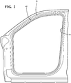
- the frame 24 supports the closure member 28 with the closure member 28 pivotable relative to the frame 24 between an open position, as shown in Figure 2 , and a closed position, as shown in Figure 7 .
- the closure member 28 In the closed position, the closure member 28 is at least partially disposed within the aperture 26 of the frame 24.
- the closure member 28 In the open position, the closure member 28 is positioned such that the closure member 28 is not substantially planar.
- the closure member 28 in the open position the closure member 28 is pivoted relative to the frame 24 such that the closure member 28 is swung away from the frame 24.
- the closure member can be a door, a hood, or a trunk lid or any item pivotably coupled to the frame 24.
- the frame 24 includes a tab 30 extending from the frame 24. More specifically, the tab 30 is disposed longitudinally along and extends inwardly into the aperture 26.
- the tab 30 has a substantial "L" configuration. Said differently, the tab 30 extends both into the aperture 26 and is bent such that the tab 30 extends toward the interior 22 of the vehicle 20.
- the tab 30 has a substantially linear configuration wherein the tab 30 only extends inwardly into the aperture 26, as shown in Figure 10 . It is to be appreciated that the tab 30 can have any suitable configuration for extending from the frame 24.
- the tab 30 has a first surface 32 and a second surface 34 opposing the first surface 32, as shown in Figure 4 .
- first surface 32 is disposed on the tab 30 such that first surface 32 faces both outwardly away from the interior 22 of the vehicle 20 and inwardly toward the aperture 26.
- the second surface 34 is disposed on the tab 30 such that the second surface 34 faces both inwardly toward the interior 22 of the vehicle 20 and outwardly away from the aperture 26 toward the frame 24.
- the first surface 32 is disposed on the tab 30 such that first surface 32 faces outwardly away from the interior 22 of the vehicle 20 and the second surface 34 faces inwardly toward the interior 22 of the vehicle 20.
- the vehicle 20 further includes a molding 36 extending along and mounted to the frame 24, as shown in Figure 3 .
- the molding 36 extends along at least a portion of the frame 24.
- the molding 36 is typically disposed at least partially within the interior 22 of the vehicle 20 and provides an aesthetic covering for the frame 24.
- the molding 36 can be a trim piece disposed along a pillar, such as an A, B, or C pillar, etc.
- the molding 36 can also be a headliner.
- the molding 36 has an outer surface 38 facing away from the adjacent frame 24.
- the molding 36 has an arcuate configuration about the frame 24 and extends to an edge 40 disposed within the aperture 26 of the frame 24.
- the molding 36 can be disposed in any configuration about the frame 24. Furthermore, it is to be appreciated that the molding 36 can be disposed outside of the vehicle 20, such that the molding 36 is not disposed within the interior 22, without escaping the scope of the subject invention.
- the vehicle 20 includes a weatherstrip assembly 42 for sealing between the frame 24 and the closure member 28 of the vehicle 20.
- the weatherstrip assembly 42 is at least partially disposed within the aperture 26 of the frame 24.
- the weatherstrip assembly 42 is mounted to and extends entirely along the frame 24 within the aperture 26. It is to be appreciated that the weatherstrip assembly 42 can be configured such that weatherstrip assembly 42 extends partially along the frame 24 within the aperture 26. It is also to be appreciated that the weatherstrip assembly 42 can extend outwardly from the aperture 26.
- the weatherstrip assembly 42 includes a trim portion 44 having a body 46 and a flange 48 extending from the body 46.
- the body 46 typically has an "L" configuration with the body 46 having a first leg 50 and a second leg 52 disposed transverse to one another and extending to distal ends.
- the flange 48 extends from the distal end of the first leg 50 and has a curvilinear configuration. More specifically, the flange 48 extends from the first leg 50 and curves toward a distal end facing the adjacent frame 24.
- the flange 48 has an interior surface 56 and an exterior surface 58 opposite the interior surface 56. Specifically, the interior surface 56 is disposed on the flange 48 facing the adjacent frame 24.
- the trim portion 44 is typically formed of a semi-rigid elastomeric material such as rubber, ethylene-propylene-diene-monomer (EPDM), Santoprene® thermoplastic elastomer (TPE) and the like. It is also to be appreciate that the trim portion 44 can be formed of a cellular or sponge EPDM having a lower density and rigidity or any combination of materials. In addition, it is to be appreciated that the trim portion 44 can be any suitable hardness or hardnesses, rigidity or rigidities, density or densities, etc. It is also to be appreciated that different combinations of materials disposed in varying locations within the trim portion 44.
- a portion of the flange 48 adjacent the exterior surface 58 is formed of sponge EPDM having a first rigidity, followed by a portion of the flange 48, first leg 50, and second leg 52 adjacent the interior surface 56 of flange 48 formed of a semi-rigid elastomeric material such as TPE having a second rigidity, followed by a portion of the body 46 formed of an even higher rigidity elastomeric material having a third rigidity, followed by a portion of the body 46 formed of a semi-rigid elastomeric material such as TPE having a fourth rigidity equivalent to the second rigidity, followed by a portion of the body 46 at the distal end of the second leg 52 formed of sponge EPDM having a fifth rigidity less than the first rigidity.
- any suitable polymeric material(s) can be utilized for the trim portion 44.
- the body 46 and the flange 48 define a channel 60 extending longitudinally along the weatherstrip assembly 42 with the tab 30 of the frame 24 extending into the channel 60 to mount the weatherstrip assembly 42 to the frame 24. More specifically, the channel 60 is defined by the "L" configuration of the body 46 between the distal end of the second leg 52 and the distal end of the flange 48.
- the tab 30 at least partially disposed within the channel 60. Specifically, the tab 30 is disposed within the channel 60 with the first surface 32 of the tab 30 adjacent to the body 46.
- the flange 48 is capable of moving between an initial position, as shown in Figure 5 , and a final position, as shown in Figure 6 . More specifically, the flange 48 is capable of flexing between the initial position flexed toward the adjacent frame 24 and the final position flexed away from the adjacent frame 24. The movement of the flange 48 can also be pivoting movement facilitated by the flange 48 having a living hinge disposed adjacent the distal end of the first leg 50 of the body 46. It is to be appreciated that the flange 48 can have any configuration for allowing movement of the flange 48 between the initial and final positions.
- the exterior surface 58 of the flange 48 abuts the edge 40 of the molding 36 with the curving toward the adjacent frame 24 such that the distal end of the flange 48 is disposed between the molding 36 and the frame 24 in the initial position.
- the interior surface 56 of the flange 48 engages the molding 36 and at least partially overlaps the molding 36 in the final position. More specifically, in the final position the flange 48 extends along the molding 36 such that the interior surface 56 of the flange 48 abuts the outer surface 38 of the molding 36. In the final position the molding 36 is partially disposed between the flange 48 and the adjacent frame 24.
- the flange 48 has a curvilinear configuration.
- the flange 48 curves toward the molding 36 in the final position to press against and seal the molding 36. Furthermore, the abutment of the flange 48 against the molding 36 in the final position creates a smooth, aesthetic transition between the weatherstrip assembly 42 and the molding 36. Movement of the flange 48 between the initial and final positions in relation to the molding 36 will be understood as the movement is described in greater detail below.
- the weatherstrip assembly 42 includes a seal 62 extending from the body 46 for abutting and sealing the closure member 28.
- the seal 62 is typically disposed along second leg 52 of the body 46 and extends away from the tab 30. More specifically, the seal 62 extends away from the interior 22 of the vehicle 20. It is to be appreciated that the seal 62 can be configured in any suitable position on the body 46 without escaping the scope of the subject invention.
- the seal 62 is configured in what is commonly referred to as a "bulb" configuration.
- the bulb configuration of the seal 62 is deformable and such that the seal 62 abuts and forms against the closure member 28 in the closed position. It is to be appreciated that the seal 62 can be any configuration for sealing against the closure member 28.
- the seal 62 is typically formed polymeric material(s) such as cellular or sponge EPDM.
- the polymeric material(s) of the seal 62 is further defined as TPE. It is to be appreciated at any suitable polymeric material(s) can be utilized for the seal 62. It is to further be appreciated that the seal 62 can be any suitable hardness or hardnesses, rigidity or rigidities, density or densities, etc.
- the seal 62 is formed of sponge EPDM. It is to be appreciated that the density and the rigidity of the seal 62 is less than the density and rigidity of the sponge EPDM of the flange 48. Talk about sponge between the seal 62 and the flange 48.
- a coating can be disposed on the seal 62 and/or the trim portion 44.
- the coating serves as an outer decorative component and is made from material which meets color, gloss and weatherability requirements of the individual application.
- the coating is molded and made preferably of a colored, weatherable grade, acrylic-styrene-acrylonitrile polycarbonate (ASA/PC) alloy.
- ASA/PC acrylic-styrene-acrylonitrile polycarbonate
- the coating can comprise combinations of nylon alloy materials, such as ASA, thermoplastic (TPO), polyacrylate polyvinyl chloride (PVC) and the like.
- the coating can be made of a film-laminated thermoplastic material, such as acrylonitrile-butadiene-styrene (ABS), polyethylene teraphthalate (PET), and polybutylene teraphthalate (PBT) and the like.
- the coating can comprise body-matched painted thermoplastic material from any variety of thermoplastic families based on ABS, PET, PBT, nylon, PA, and the like.
- the weatherstrip assembly 42 includes an adhesive 64 disposed on the body 46 for coupling the trim portion 44 to the frame 24.
- the adhesive 64 is disposed opposite the seal 62 such that the seal 62 extends away from the adhesive 64. More specifically, the adhesive 64 is disposed on the second leg 52 of the body 46 opposite the seal 62 facing the interior 22 of the vehicle 20 and extends longitudinally along the body 46. It is to be appreciated that the adhesive 64 can be disposed on the first leg 50 of the body 46 facing the adjacent frame 24 with escaping the scope of the subject invention. Furthermore, it is to be appreciated that the adhesive 64 can be positioned in any configuration for coupling the trim portion 44 to the frame 24.
- the adhesive 64 abuts the first surface 32 of the tab 30. Abutment of the adhesive 64 with the first surface 32 couples the trim portion 44 to the frame 24.
- the adhesive 64 is a double-sided tape for coupling together the trim portion 44 and the frame 24.
- the adhesive 64 can be glue, epoxy, or any other suitable adhesive 64.
- the weatherstrip assembly 42 includes a retaining member 66 extending from the flange 48 to an abutment end 68 in an arcuate configuration.
- the retaining member 66 selectively mounted to the flange 48 and spaced from the adhesive 64. More specifically, the retaining member 66 is removable from the flange 48.
- the retaining member 66 is disposed on the interior surface 56 of the flange 48 between distal end of the first leg 50 of the body 46 and the distal end of the flange 48.
- the retaining member 66 extends into the channel 60 defined by the body 46 and the flange 48, as shown in Figure 4 .
- the retaining member 66 includes a body portion 70 and a dividing section 72 extending from the retaining member 66 to the flange 48.
- the dividing section 72 has a tensile strength less than a tensile strength of the flange 48 such that the retaining member 66 separates at the dividing section 72 during the removal of the retaining member 66 from the flange 48. Furthermore, the tensile strength of the dividing section 72 is less than the tensile strength of the body portion 70 of the retaining member 66 to prevent separation within the body portion 70.
- the dividing section 72 is defined as at least one stem 74 having a cross-sectional area less than a cross-sectional area of the flange 48 adjacent the stem 74.
- the reduced cross-sectional area of the at least one stem 74 relative to the cross-sectional area of the flange 48 and the body portion 70 ensures separation of the retaining member 66 from the flange 48 at the at least one stem 74.
- the reduced cross-sectional area of the at least one stem 74 causes the reduction in tensile strength at the dividing section 72.
- the at least one stem 74 is defined as one stem 74 extending from the retaining member 66 to the flange 48, as shown in Figures 4,5 , 9 , and 10 .
- the at least one stem 74 can be further defined as two stems 74 extending from the retaining member 66 to the flange 48. It is to be appreciated that the at least one stem 74 can comprise any number of stems 74 without escaping the scope of the subject invention. It is also to be appreciated that the dividing sections 72 can be any suitable configuration for separating the retaining member 66 from the flange 48. As non-limiting examples, the dividing section 72 can be defined as one or more perforations (See Figure 8 ) extending through the retaining member 66 adjacent the flange 48. Furthermore, the dividing section 72 can comprise a material dissimilar to the material of the body portion 70 and the flange 48.
- the body portion 70 extends to both the dividing section 72 and the abutment end 68 opposite the dividing section 72 with the body portion 70 having the arcuate configuration between the dividing section 72 and the abutment end 68. More specifically, the abutment end 68 faces at least one of the flange 48 and the body 46 for abutting the frame 24. As shown in Figures 4, 5 , 8, and 9 , the abutment end 68 faces the flange 48 for engaging the second surface 34 of the tab 30 in the "L" configuration. As shown in Figure 10 , the abutment end 68 faces the body 46 for engaging the second surface 34 of the tab 30 in the linear configuration.
- the retaining member 66 selectively engages the second surface 34 to grip the tab 30 between the adhesive 64 and the retaining member 66.
- the retaining member 66 is typically formed of a semi-rigid elastomeric material such as rubber, ethylene-propylene-diene-monomer (EPDM), Santoprene® thermoplastic elastomer (TPE) and the like. It is also to be appreciate that the trim portion 44 can be formed of a cellular or sponge EPDM having a lower density and rigidity. In addition, it is to be appreciated that the trim portion 44 can be any suitable hardness or hardnesses, rigidity or rigidities, density or densities, etc. It is to further be appreciated at any suitable polymeric material(s) can be utilized for the retaining member 66.
- the weatherstrip assembly 42 includes a cord 76 at least partially disposed within the retaining member 66. More specifically, the cord 76 is disposed within the body portion 70 of the retaining member 66 and extends longitudinally along the retaining member 66. It is to be appreciated that the cord 76 can extend from the body portion 70 to allow additional material to facilitate removal of the retaining member 66.
- the cord 76 provides access to the retaining member 66 and is configured to facilitate the removal of the retaining member 66 from the flange 48.
- the cord 76 can be formed of polymeric material(s).
- the polymeric material(s) of the cord 76 can be thermoplastic material(s) and/or themoset material(s). It is to be appreciated that the cord 76 can be formed of the material(s) as discussed above for the trim portion 44.
- the cord 76 is formed of material(s) having a higher strength, rigidity and density than the retaining member 66. As such, the cord 76 locally strengthens a portion of the retaining member 66 about the cord 76.
- the strength imparted by the cord 76 prevents the retaining member 66 from severing during separation from the flange 48.
- the retaining member 66 can be any suitable hardness or hardnesses, rigidity or rigidities, density or densities, etc.
- the retaining member 66 is selectively mounted to the body 46 spaced from the selective mounting of the retaining member 66 to the flange 48 such that the retaining member 66 is selectively mounted to each of the body 46 and the flange 48.
- the body 46 includes a protrusion 78 extending to an end 80 with the retaining member 66 selectively mounted to the end 80 of the protrusion 78 of the body 46 and the flange 48.
- the protrusion 78 extends from and is transverse to the second leg 52 of the body 46. More specifically, the protrusion 78 extends away from the seal 62 and is disposed longitudinally along the trim portion 44.
- the retaining member 66 includes a body dividing section 82 extending from the retaining member 66 toward the protrusion 78 to selectively mount the retaining member 66 to the end 80 of the protrusion 78.
- the body dividing section 82 is structurally equivalent to the dividing section 72 as set forth above.
- the body dividing section 82 has a tensile strength equivalent, or at least substantially similar, to the dividing section 72 above with the body dividing section 82 having a tensile strength less than a tensile strength of the protrusion 78 such that the retaining member 66 separates at the body dividing section 82 during the removal of the retaining member 66 from the flange 48.
- the tensile strength of the body dividing section 82 is less than the tensile strength of the body portion 70 of the retaining member 66 to prevent separation within the body portion 70.
- the body dividing section 82 is defined as at least one body stem 84 having a cross-sectional area less than a cross-sectional area of the protrusion 78 adjacent the body stem 84, similar to the stem 74 of the dividing section 72. As shown in Figures 8 and 9 the at least one body stem 84 is defined as one body stem 84 extending from the retaining member 66 to the flange 48. It is to be appreciated that the at least one body stem 84 can comprise any number of body stems 84 without escaping the scope of the subject invention. It is also to be appreciated that the body dividing section 82 can be any suitable configuration for separating the retaining member 66 from the protrusion 78.
- the body dividing section 82 can be defined as a plurality of perforations extending through the retaining member 66 adjacent the protrusion 78. Furthermore, the body dividing section 82 can comprise a material dissimilar to the material of the body portion 70 and the protrusion 78.
- the abutment end 68 of the retaining member 66 faces the flange 48 for engaging the second surface 34 of the tab 30 in the "L" configuration.
- the protrusion 78 extends adjacent to the first surface 32 of the tab 30.
- the arcuate configuration of the retaining member 66 extends around the tab 30 to the second surface 34 such that the abutment end 68 engages the second surface 34.
- the abutment end 68 faces the body 46 for engaging the second surface 34 of the tab 30 in the linear configuration.
- the protrusion 78 extends transverse to the tab 30 with the tab 30 extending past the second surface 34.
- the arcuate configuration of the retaining member 66 extends from the protrusion 78 toward the around the tab 30 to the second surface 34 such that the abutment end 68 engages the second surface 34.
- the weatherstrip assembly 42 is disposed adjacent the tab 30 of the frame 24.
- the retaining member 66 selectively engages the frame 24 to selectively hold the flange 48 in the initial position relative to the frame 24. More specifically, the abutment end 68 of the retaining member 66 engages the second surface 34 of the tab 30. Engagement of the retaining member 66 with the tab 30 also facilitates proper alignment along the frame 24 with the engagement allowing for adjustments in the positioning of the weatherstrip assembly 42.
- the weatherstrip assembly 42 is then manipulated to bring the adhesive 64 into engagement with the first surface 32 of the tab 30.
- the retaining member 66 is pivotable about the dividing section 72 relative to the flange 48 to facilitate coupling of the trim portion 44 and the frame 24. Furthermore, the retaining member 66 is pivotable about the body dividing section 82 relative to the body 46 to facilitate coupling of the trim portion 44 and the frame 24.
- the adhesive 64 adheres the trim portion 44 to the first surface 32 of the tab 30. Adherence to the tab 30 can occur instantaneously upon engagement or can occur temporally.
- the molding 36 is mounted to the frame 24, as shown in Figure 5 .
- the retaining member 66 is no longer needed to hold the weatherstrip assembly 42 to the frame 24.
- the retaining member 66 is removed from the flange 48 while concurrently moving the flange 48 toward the final position, as shown in Figure 12 . More specifically, the retaining member 66 is removed from the trim portion 44 and, if applicable, the body 46. Beginning at a one end of the weatherstrip assembly 42, the cord 76 is engaged facilitating the separation of the retaining member 66 from the flange 48 at the dividing section 72 and, if applicable, the body 46 at the body dividing section 82.
- the cord 76 and the retaining member 66 are pulled toward flange 48 causing the retaining member 66 to progressively and selectively abut along the flange 48. Abutment of the retaining member 66 with the flange 48 causes the flange 48 to move from the initial position around the edge 40 of the molding 36 to the final position with the flange 48 the interior surface 56 of the flange 48 abutting the outer surface 38 of the molding 36. The flange 48 progressively moves from the initial position to the final position along the entirety of the weatherstrip assembly 42 as the cord 76 and the retaining member 66 are removed. When the cord 76 and the retaining member 66 are completely removed, the flange 48 is completely disposed in the final position, as shown in Figure 6 .
- the subject invention also discloses a method of assembling the weatherstrip assembly 42 on the vehicle 20 with the vehicle 20 having the frame 24 and the molding 36, and the weatherstrip assembly 42 having the body 46 and the flange 48, as shown in Figure 4 .
- the seal 62 extends from the body 46 and the adhesive 64 is disposed on the body 46 opposite the seal 62.
- the retaining member 66 includes the dividing section 72 and is selectively mounted to the flange 48 and the cord 76 is at least partially disposed within the retaining member 66.
- the method includes the steps of engaging the retaining member 66 to the frame 24, manipulating the body 46 and the flange 48 relative to the retaining member 66 about the frame 24, and engaging the adhesive 64 with the frame 24, as shown in Figure 4 .
- the method further includes the step of pivoting the body 46 and the flange 48 relative to the retaining member 66 about the dividing section 72.
- the method includes the steps of mounting the molding 36 on the frame 24, as shown in Figure 5 , and pulling the cord 76 away from the flange 48, as shown in Figures 6 and 12 , with the step of pulling the cord 76 occurring after the adhesive 64 adheres to the frame 24.
- the method further includes the steps of separating the retaining member 66 from the flange 48 and moving the flange 48 from the initial position on one side of the molding 36 to the final position on an opposing side of the molding 36, with the steps of pulling the cord 76 and separating the retaining member 66 from the flange 48 occur simultaneously and the steps of separating the retaining member 66 from the flange 48 and moving the flange 48 occur simultaneously. Furthermore, the method includes the step of abutting the flange 48 with the molding 36.
- FIG. 11 another embodiment of a weatherstrip assembly 86 for sealing between the frame 24 and the closure member 28 of the vehicle 20 is generally shown. Similar to the embodiments discussed above, the assembly includes the trim portion 44 having the body 46 and the flange 48 extending from the body 46 with the flange 48 capable of moving relative to the body 46 between the initial position and the final position.
- the seal 62 extends from the body 46 for abutting and sealing the closure member 28.
- the adhesive 64 is disposed on the body 46 for coupling the trim portion 44 to the frame 24.
- the adhesive 64 is disposed opposite the seal 62 such that the seal 62 extends away from the adhesive 64.
- the weatherstrip assembly 86 further includes the retaining member 66 extending from the flange 48 to the abutment end 68 in the arcuate configuration with the abutment end 68 facing at least one of the flange 48 and the body 46 for abutting the frame 24. More specifically, as shown in Figure 11 , the abutment end 68 of faces the flange 48 for abutting the second surface 34 of the "L" configured tab 30.
- the retaining member 66 mounted to the flange 48 and spaced from the adhesive 64 for engaging the frame 24 to selectively hold the flange 48 in the initial position relative to the frame 24. More specifically, the retaining member 66 is configured to be permanently mounted to the flange 48.
- the cord 76 is selectively mounted to and extends longitudinally along the flange 48 spaced from the retaining member 66. More specifically, the weatherstrip assembly 86 includes a covering 88 selectively mounted to the flange 48 with the cord 76 disposed longitudinally within the covering 88.
- the covering 88 is comprised of a material equivalent to the retaining member 66 as set for above. However, it is to be appreciated that the cord 76 can be any suitable material.
- the covering 88 includes a cord dividing section 90 extending from the retaining member 66 to the flange 48.
- the cord dividing section 90 has a tensile strength less than the tensile strength of the flange 48 such that the covering 88 separates at the cord dividing section 90 during the removal of the cord 76 from the flange 48.
- the weatherstrip assembly 86 is disposed adjacent the tab 30 of the frame 24.
- the retaining member 66 selectively engages the frame 24 to selectively hold the flange 48 in the initial position relative to the frame 24.
- the weatherstrip assembly 86 is then manipulated to bring the adhesive 64 into engagement with the first surface 32 of the tab 30.
- the adhesive 64 adheres the trim portion 44 to the first surface 32 of the tab 30. Adherence to the tab 30 can occur instantaneously upon engagement or can occur temporally. Next, the molding 36 is mounted to the frame 24.
- the cord 76 is removed from the flange 48 while concurrently moving the flange 48 toward the final position. Beginning at a one end of the weatherstrip assembly 86, the cord 76 is engaged facilitating the separation of the covering 88 from the flange 48 at the cord dividing section 90.
- the cord 76 is pulled toward flange 48 causing the covering 88 to progressively and selectively abut along the flange 48. Abutment of the covering 88 with the flange 48 causes the flange 48 to move from the initial position around the edge 40 of the molding 36 to the final position with the flange 48 the interior surface 56 of the flange 48 abutting the outer surface 38 of the molding 36. The flange 48 progressively moves from the initial position to the final position along the entirety of the weatherstrip assembly 86 as the cord 76 and the cover are removed. When the cord 76 and the cover are completely removed, the flange 48 is completely disposed in the final position.
Landscapes
- Engineering & Computer Science (AREA)
- Mechanical Engineering (AREA)
- Civil Engineering (AREA)
- Structural Engineering (AREA)
- Seal Device For Vehicle (AREA)
Claims (15)
- Dichtungsleistenanordnung (42, 86) zum Abdichten, zwischen einem Rahmen (24) und einem Schliesselement (28) eines Fahrzeuges (20), welche Anordnung (42, 86) umfasst:ein Verkleidungsteilstück (44) mit einem Körper (46) und einem Flansch (48), der sich von diesem Körper (46) aus erstreckt, wobei der Flansch (48) zwischen einer Anfangsposition und einer Endposition bewegbar ist; eine Dichtung (62), die sich von diesem Körper (46) weg erstreckt, um an dem Schliesselement (28) anzuliegen und dieses abzudichten; ein Kleberelement (64), das an diesem Körper (46) angeordnet ist, um dieses Verkleidungsteilstück (44) mit dem Rahmen (24) zu verbinden, wobei das Kleberelement (64) gegenüber dieser Dichtung (62) so angeordnet ist, dass sich diese Dichtung (62) von dem Kleberelement (64) weg erstreckt; undwobeidiese Dichtungsleistenanordnung (42, 86) ein Halteelement (66) aufweist, welches an diesem Flansch (48) befestigt und von diesem Kleberelement (64) beabstandet ist, und um den Rahmen (24) zu hintergreifen, um diesen Flansch (48) in dieser Ausgangsposition relativ zum Rahmen (24) zu halten,dadurch charakterisiert, dassdieses Halteelement (66) von dem Flansch (48) entfernt wird, während sich der Flansch (48) gleichzeitig zur Endposition bewegt.
- Dichtungsleistenanordnung (42, 86) nach Anspruch 1, wobei sich das Halteelement (66) in einer bogenförmigen Konfiguration von dem Flansch (48) zu einem Anschlagende (68) erstreckt, wobei dieses Anschlagende(68) zumindest dem Flansch (48) oder dem Körper (46) zugewandt ist, um am Rahmen (24) anzuliegen.
- Dichtungsleistenanordnung (42, 86) nach einem der Ansprüche 1 oder 2, wobei das Halteelement (66) einen Trennabschnitt (72) aufweist, welcher sich von dem Halteelement (66) zum Flansch (48) erstreckt, wobei der Trennabschnitt (72) eine Zugfestigkeit aufweist, welche geringer als eine Zugfestigkeit des Flansches (48) ist, so dass sich, während des Entfernens des Halteelementes (66), das Halteelement (66) an der Stelle dieses Trennabschnittes (72) von dem Flansch (48) trennt.
- Dichtungsleistenanordnung (42, 86) nach Anspruch 3, wobei dieser Trennabschnitt (72) als mindestens ein Schaft (74) definiert ist, der eine Querschnittsfläche aufweist, die kleiner ist als eine benachbart zum Schaft (74) liegende Querschnittsfläche des Flansches (48).
- Dichtungsleistenanordnung (42, 86) nach Anspruch 3, wobei das Halteelement (66) um den Trennabschnitt (72) relativ zu dem Flansch (48) schwenkbar ist, um die Verbindung des Verkleidungsteilstückes (44) mit dem Rahmen (24) zu erleichtern.
- Dichtungsleistenanordnung (42, 86) nach einem der Ansprüche 1 bis 5, wobei das Halteelement (66) einen Körperabschnitt (70) umfasst, welcher sich sowohl zu einem Trennabschnitt (72) als auch zu einem dem Trennabschnitt gegenüberliegenden Anschlagende (68) erstreckt, wobei dieser Körperabschnitt (70) eine bogenförmige Konfiguration zwischen dem Trennabschnitt (72) und dem Anschlagende (68) aufweist.
- Dichtungsleistenanordnung (42, 86) nach einem der Ansprüche 1 bis 6, wobei das Halteelement (66) an diesem Körper (46), von der Befestigung des am Flansch (48) angebrachten Halteelementes (66) beabstandet, angebracht ist, so dass das Halteelement (66) an sowohl dem Körper (46) als auch dem Flansch (48) angebracht ist.
- Dichtungsleistenanordnung (42, 86) nach einem der Ansprüche 1 bis 7, welche ferner eine Kordel (76) aufweist, die zumindest teilweise innerhalb des Halteelementes (66) angeordnet ist, wobei die Kordel (76) einen Zugang zu dem Halteelement (66) schafft und so gestaltet ist, um das Entfernen des Halteelementes (66) von dem Flansch (48) zu erleichtern.
- Fahrzeug (20) mit einem Rahmen (24), einem Schliesselement 28), welches schwenkbar mit diesem Rahmen (24) verbunden ist, und mit einer Dichtungsleistenanordnung (42, 86) gemäss einem der vorhergehenden Ansprüche.
- Fahrzeug (20) nach Anspruch 9, ferner umfassend ein Formteil (36), das sich entlang des Rahmens (24) erstreckt und an diesem angebracht ist, und wobei der Flansch (48) eine Innenfläche (56) aufweist, wobei die Innenfläche (56) in das Formteil (36) eingreift und der Flansch (48) das Formteil (36) in der Endposition zumindest teilweise überlappt.
- Fahrzeug (20) nach Anspruch 9, wobei der Rahmen (24) eine Lasche (30) aufweist, die sich von dem Rahmen (24) weg erstreckt, wobei der Körper (46) und der Flansch (48 einen Kanal (60) definieren, der sich in Längsrichtung entlang der Dichtungsleistenanordnung (42, 86) erstreckt, wobei sich die Lasche (30) des Rahmens (24) in den Kanal (60) erstreckt, wobei die Lasche (30) eine erste Oberfläche (32) und eine der ersten Oberfläche (32) gegenüberliegende zweite Oberfläche (34) aufweist, und wobei das Kleberelement (64) an der ersten Oberfläche (32) anliegt und das Halteelement (66) die zweite Oberfläche (34) hintergreift, um die Lasche (30) zwischen dem Kleberelement (64) und dem Halteelement (66) zu ergreifen, um die Dichtungsleistenanordnung (42, 86) an dem Rahmen (24) zu befestigen.
- Verfahren um eine Dichtungsleistenanordnung (42, 86) gemäss einem der Ansprüche 1 bis 11 an einem Fahrzeug (20) zu montieren, wobei das Fahrzeug (20) einen Rahmen (24) und ein Formteil (36) aufweist, und wobei die Dichtungsleistenanordnung (42, 86) einen Körper (46) und einen Flansch (48) aufweist, sowie eine Dichtung (62), die sich vom Körper (46) weg erstreckt, und ein Kleberelement (64), das an dem Körper (46) gegenüber der Dichtung (62) angeordnet ist, sowie ein Halteelement (66), das an dem Flansch (48) angebracht ist, und eine Kordel (76), die zumindest teilweise innerhalb des Halteelements (66) angeordnet ist; wobei das Verfahren die folgenden Schritte umfasst:in Eingriff bringen des Halteelements (66) mit dem Rahmen (24);Führen des Körpers (46) und des Flansches (48) relativ zu dem Halteelement (66) und um den Rahmen (24) herum;Verbinden des Kleberelementes (64) mit dem Rahmen (24);Befestigen des Formteils (36) am Rahmen (24);Wegziehen der Kordel (76) vom Flansch (48);Abtrennen des Halteelementes (66) vom Flansch (48);Bewegen des Flansches (48) von einer Anfangsposition auf einer Seite des Formteils (36) zu einer Endposition auf einer gegenüberliegenden Seite des Formteils (36); undin Anschlag bringen des Flansches (48) mit dem Formteil (36).
- Verfahren nach Anspruch 12, wobei der Schritt des Wegziehens der Kordel (76) erfolgt, nachdem das Kleberelement (64) an dem Rahmen (24) haftet.
- Verfahren nach einem der Ansprüche 12 oder 13, wobei die Schritte des Wegziehens der Kordel (76) und des Abtrennens des Halteelementes (66) von dem Flansch (48) gleichzeitig erfolgen.
- Verfahren nach einem der Ansprüche 12 bis 14, wobei die Schritte des Abtrennens des Halteelementes (66) von dem Flansch (48) und des Bewegens des Flansches (48) gleichzeitig erfolgen.
Priority Applications (1)
| Application Number | Priority Date | Filing Date | Title |
|---|---|---|---|
| PL12831140T PL2755866T3 (pl) | 2011-09-15 | 2012-09-17 | Zespół taśmy chroniącej przed czynnikami atmosferycznymi mający zdejmowalny zatrzymujący element |
Applications Claiming Priority (2)
| Application Number | Priority Date | Filing Date | Title |
|---|---|---|---|
| US201161535085P | 2011-09-15 | 2011-09-15 | |
| PCT/US2012/055782 WO2013040573A1 (en) | 2011-09-15 | 2012-09-17 | Weatherstrip assembly having a removable retaining member |
Publications (3)
| Publication Number | Publication Date |
|---|---|
| EP2755866A1 EP2755866A1 (de) | 2014-07-23 |
| EP2755866A4 EP2755866A4 (de) | 2015-08-12 |
| EP2755866B1 true EP2755866B1 (de) | 2017-12-20 |
Family
ID=47883828
Family Applications (1)
| Application Number | Title | Priority Date | Filing Date |
|---|---|---|---|
| EP12831140.4A Not-in-force EP2755866B1 (de) | 2011-09-15 | 2012-09-17 | Dichtungsleiste mit einem entfernbaren halteelement |
Country Status (5)
| Country | Link |
|---|---|
| US (2) | US9227499B2 (de) |
| EP (1) | EP2755866B1 (de) |
| ES (1) | ES2661711T3 (de) |
| PL (1) | PL2755866T3 (de) |
| WO (1) | WO2013040573A1 (de) |
Families Citing this family (8)
| Publication number | Priority date | Publication date | Assignee | Title |
|---|---|---|---|---|
| PL2755866T3 (pl) | 2011-09-15 | 2018-06-29 | Henniges Automotive Sealing Systems North America, Inc. | Zespół taśmy chroniącej przed czynnikami atmosferycznymi mający zdejmowalny zatrzymujący element |
| DE102012106340B4 (de) | 2012-07-13 | 2022-07-14 | Bayerische Motoren Werke Aktiengesellschaft | Dichtungsstrang zur Verklebung mit einer Fahrzeugkarosserie |
| PL2803518T3 (pl) * | 2013-05-15 | 2018-04-30 | Henniges Automotive Sealing Systems North America, Inc. | Uszczelniający element |
| US10315349B2 (en) | 2014-02-07 | 2019-06-11 | Henniges Automotive Sealing Systems North America, Inc. | Sealing assembly for a vehicle and method of manufacturing a sealing assembly |
| WO2016172483A1 (en) * | 2015-04-24 | 2016-10-27 | Quick Fix Solutions, Inc. | Sealing device and method of installation |
| DE102017123419A1 (de) * | 2017-10-09 | 2019-04-11 | Cqlt Saargummi Technologies S.À.R.L. | Dichtungsstrang, insbesondere zur Verarbeitung als Endlosstrang |
| USD930536S1 (en) * | 2019-07-12 | 2021-09-14 | Jinhao Guo | Weatherstrip for car door |
| US11351847B2 (en) * | 2020-03-31 | 2022-06-07 | Toyota Motor Engineering & Manufacturing North America, Inc. | Clipless hood seal |
Family Cites Families (50)
| Publication number | Priority date | Publication date | Assignee | Title |
|---|---|---|---|---|
| US2260129A (en) * | 1939-05-10 | 1941-10-21 | Briggs Mfg Co | Sealing strip |
| US2954592A (en) * | 1957-05-27 | 1960-10-04 | Goodrich Co B F | Resilient gasket |
| GB1597127A (en) | 1977-10-04 | 1981-09-03 | Draftex Dev Ag | Channel-shaped sealing and finishing strips |
| GB2024294B (en) | 1978-06-30 | 1982-11-17 | Draftex Dev Ag | Channel-shaped sealing |
| DE3346070A1 (de) | 1983-12-21 | 1985-08-08 | Metzeler Kautschuk GmbH, 8000 München | Dichtungsprofil |
| GB2153421B (en) | 1984-01-27 | 1987-08-12 | Draftex Ind Ltd | Sealing strip |
| GB2160920B (en) | 1984-06-26 | 1987-10-14 | Draftex Ind Ltd | Sealing strip |
| DE3824088A1 (de) | 1988-07-15 | 1990-01-25 | Metzeler Gmbh | Verfahren zur festlegung eines fensterfuehrungsprofils |
| US5010691A (en) * | 1989-08-08 | 1991-04-30 | The Standard Products Company | Weather seal for a door |
| US5174066A (en) | 1989-09-26 | 1992-12-29 | Gencorp Inc. | Door glass cassette for vehicles |
| US4976068A (en) * | 1989-10-19 | 1990-12-11 | The Standard Products Company | Repositioning device for a weather seal |
| JP2543917Y2 (ja) | 1991-07-10 | 1997-08-13 | 豊田合成株式会社 | ウェザストリップ |
| WO1993015298A1 (en) * | 1992-01-23 | 1993-08-05 | Ian Thomas Howe | Door draught and weather excluder |
| US5449544A (en) | 1992-06-06 | 1995-09-12 | Toyoda Gosei Co., Ltd. | Weather strip for an automobile and a method for assembling the same |
| DE4308218C2 (de) | 1993-03-15 | 1996-11-07 | Metzeler Automotive Profiles | Dichtungsanordnung |
| DE59400458D1 (de) | 1994-11-29 | 1996-08-29 | Henniges Elastomer Kunststoff | Vorrichtung zum Einfassen der Ränder der Fensterscheiben von Kraftfahrzeugen |
| JPH08216687A (ja) | 1995-02-16 | 1996-08-27 | Nishikawa Rubber Co Ltd | ドアウエザーストリップ |
| FR2781429B1 (fr) * | 1998-07-21 | 2000-10-13 | Peugeot | Bande auto-adhesive constituant par exemple un joint pour vehicule automobile |
| JP3635959B2 (ja) | 1998-12-28 | 2005-04-06 | 豊田合成株式会社 | ドアウエザストリップのシール構造 |
| US6131341A (en) * | 1999-01-25 | 2000-10-17 | Ford Global Technologies, Inc. | Sealing system for vehicle door |
| JP4141605B2 (ja) | 1999-11-22 | 2008-08-27 | 西川ゴム工業株式会社 | ウェザーストリップと、その取付構造 |
| JP4304395B2 (ja) | 1999-12-10 | 2009-07-29 | 豊田合成株式会社 | 自動車用ウェザストリップ |
| US7422788B2 (en) | 2000-12-21 | 2008-09-09 | Webasto Ag And Rehau Ag & Co. | Double-sided adhesive tape and method for fixing a sealing element in place |
| JP4590757B2 (ja) | 2001-03-12 | 2010-12-01 | 豊田合成株式会社 | 自動車のシール構造 |
| DE10118661B4 (de) * | 2001-04-14 | 2006-04-13 | Saint-Gobain Sekurit Deutschland Gmbh & Co. Kg | Verklebbare Fensterscheibe mit Reißschnur |
| JP3542785B2 (ja) | 2001-06-28 | 2004-07-14 | 西川ゴム工業株式会社 | 自動車用ウェザーストリップと、その成形方法 |
| DE20211948U1 (de) | 2002-08-03 | 2003-12-18 | Nothelfer Gmbh | Verbindung der Ränder von geformten Blechen |
| DE20216759U1 (de) | 2002-10-31 | 2003-01-30 | SaarGummi GmbH, 66687 Wadern | Dichtungsstrang für Karosseriedichtungen mit bereichsweise verstärktem Dichtungsprofil |
| DE10252595B3 (de) | 2002-11-12 | 2004-05-06 | Metzeler Automotive Profile Systems Gmbh | Dichtung, insbesondere zum Abdichten einer Tür, einer Fensterscheibe oder des Dachs eines Kraftfahrzeugs |
| US6814393B2 (en) | 2003-03-24 | 2004-11-09 | Toyoda Gosei Co., Ltd. | Sealing strip and vehicle panel assembly |
| FR2853595B1 (fr) | 2003-04-11 | 2005-06-24 | Hutchinson | Joint d'etancheite destine a etre monte sur une porte de vehicule a moteur presentant au moins un angle a faible rayon de courbure. |
| FR2853594B1 (fr) | 2003-04-11 | 2008-02-15 | Hutchinson | Joint d'etancheite destine a etre monte sur le pourtour d'une porte de vehicule a moteur presentant au moins un angle a faible rayon de courbure. |
| US6846034B1 (en) | 2004-01-08 | 2005-01-25 | Ford Global Technologies, Llc | Vehicular weather strip |
| JP4559282B2 (ja) | 2005-04-11 | 2010-10-06 | 西川ゴム工業株式会社 | クリップ及びウェザーストリップの取付方法 |
| JP4529818B2 (ja) | 2005-06-30 | 2010-08-25 | 豊田合成株式会社 | 自動車用ウエザストリップ |
| US20070024084A1 (en) | 2005-07-28 | 2007-02-01 | Toyoda Gosei Co., Ltd. | Weather strip |
| US20070180776A1 (en) | 2005-07-28 | 2007-08-09 | Toyoda Gosei Co., Ltd. | Weather strip |
| JP2007230283A (ja) | 2006-02-28 | 2007-09-13 | Toyoda Gosei Co Ltd | 自動車用ウエザストリップ |
| JP2007253794A (ja) | 2006-03-23 | 2007-10-04 | Toyoda Gosei Co Ltd | ウエザストリップの取付け方法 |
| US20070245634A1 (en) | 2006-03-23 | 2007-10-25 | Toyoda Gosei Co., Ltd. | Weather strip |
| JP4784825B2 (ja) | 2006-04-24 | 2011-10-05 | 豊田合成株式会社 | 自動車用ウエザストリップ |
| JP4937829B2 (ja) * | 2007-05-10 | 2012-05-23 | 西川ゴム工業株式会社 | 自動車用ウエザーストリップ |
| DE102008011397B4 (de) * | 2008-02-22 | 2026-04-23 | Cqlt Saargummi Technologies S.À.R.L. | Dichtungsstrang |
| FR2928170A1 (fr) * | 2008-02-29 | 2009-09-04 | Peugeot Citroen Automobiles Sa | Joint d'etancheite pour encardrement d'un ouvrant, notamment de type porte ou fenetre |
| US7845707B2 (en) | 2008-03-12 | 2010-12-07 | Gm Global Technology Operations, Inc. | Vehicle closure assembly with shape memory polymer seal |
| GB2459467B (en) | 2008-04-23 | 2013-01-30 | Land Rover Uk Ltd | A motor vehicle door seal |
| JP2010149838A (ja) | 2008-09-30 | 2010-07-08 | Toyoda Gosei Co Ltd | 自動車用オープニングトリムウェザストリップ |
| PL2755866T3 (pl) | 2011-09-15 | 2018-06-29 | Henniges Automotive Sealing Systems North America, Inc. | Zespół taśmy chroniącej przed czynnikami atmosferycznymi mający zdejmowalny zatrzymujący element |
| US8919846B2 (en) * | 2012-05-04 | 2014-12-30 | Srg Global, Inc. | Daylight opening system for vehicle |
| DE102012106340B4 (de) | 2012-07-13 | 2022-07-14 | Bayerische Motoren Werke Aktiengesellschaft | Dichtungsstrang zur Verklebung mit einer Fahrzeugkarosserie |
-
2012
- 2012-09-17 PL PL12831140T patent/PL2755866T3/pl unknown
- 2012-09-17 ES ES12831140.4T patent/ES2661711T3/es active Active
- 2012-09-17 WO PCT/US2012/055782 patent/WO2013040573A1/en not_active Ceased
- 2012-09-17 US US14/345,140 patent/US9227499B2/en not_active Expired - Fee Related
- 2012-09-17 EP EP12831140.4A patent/EP2755866B1/de not_active Not-in-force
-
2016
- 2016-01-05 US US14/988,151 patent/US9676261B2/en active Active
Non-Patent Citations (1)
| Title |
|---|
| None * |
Also Published As
| Publication number | Publication date |
|---|---|
| US9676261B2 (en) | 2017-06-13 |
| US20140366451A1 (en) | 2014-12-18 |
| EP2755866A1 (de) | 2014-07-23 |
| EP2755866A4 (de) | 2015-08-12 |
| WO2013040573A1 (en) | 2013-03-21 |
| PL2755866T3 (pl) | 2018-06-29 |
| US20160207384A1 (en) | 2016-07-21 |
| ES2661711T3 (es) | 2018-04-03 |
| US9227499B2 (en) | 2016-01-05 |
Similar Documents
| Publication | Publication Date | Title |
|---|---|---|
| US9676261B2 (en) | Weatherstrip assembly having a removable retaining member | |
| US9027284B2 (en) | Sealing member | |
| EP1918141B1 (de) | Türverkleidung für ein Fahrzeug | |
| US20120297726A1 (en) | Decorative Molding With Film | |
| US20120025564A1 (en) | Flush Glass System Module | |
| CN101688423A (zh) | 与腰线、玻璃滑槽和上部窗侧一体的金属装饰条 | |
| US20100313487A1 (en) | Applique with integrated end cap and window molding | |
| US20070227072A1 (en) | Outer Belt Molding | |
| US20110109009A1 (en) | Method of forming unsupported division post for automotive glass encapsulation | |
| US20100102597A1 (en) | Glass Run With Integrated Upper Reveal | |
| EP1812257B1 (de) | Innenbeschlaganordnung | |
| US20050057058A1 (en) | Carrierless flange cover with integral trim strip | |
| US9956853B2 (en) | Glass pane having a profiled joint and trim, trim and production method for the glass pane | |
| US20160272056A1 (en) | Opening trim weatherstrip | |
| US20070024084A1 (en) | Weather strip | |
| US20080073927A1 (en) | Vehicle trim component storage compartment and method of making same | |
| JP2011218845A (ja) | ウエザストリップ | |
| US11691490B2 (en) | Seal assembly | |
| EP2803518B1 (de) | Dichtungselement | |
| US9174519B2 (en) | Weatherstrip assembly having a variable length shim | |
| US20070180776A1 (en) | Weather strip | |
| JP2003104068A (ja) | ウエザーストリップの取付構造 | |
| US20130067822A1 (en) | Two-shot secondary seal | |
| JP2008030636A (ja) | オープニングトリムウエザストリップ | |
| JP3873677B2 (ja) | ウエザーストリップ、その製造方法及びその取付構造 |
Legal Events
| Date | Code | Title | Description |
|---|---|---|---|
| PUAI | Public reference made under article 153(3) epc to a published international application that has entered the european phase |
Free format text: ORIGINAL CODE: 0009012 |
|
| 17P | Request for examination filed |
Effective date: 20140314 |
|
| AK | Designated contracting states |
Kind code of ref document: A1 Designated state(s): AL AT BE BG CH CY CZ DE DK EE ES FI FR GB GR HR HU IE IS IT LI LT LU LV MC MK MT NL NO PL PT RO RS SE SI SK SM TR |
|
| DAX | Request for extension of the european patent (deleted) | ||
| RA4 | Supplementary search report drawn up and despatched (corrected) |
Effective date: 20150709 |
|
| RIC1 | Information provided on ipc code assigned before grant |
Ipc: B60R 13/06 20060101AFI20150703BHEP Ipc: B60J 10/08 20060101ALI20150703BHEP Ipc: B60J 10/00 20060101ALI20150703BHEP |
|
| REG | Reference to a national code |
Ref country code: DE Ref legal event code: R079 Ref document number: 602012041192 Country of ref document: DE Free format text: PREVIOUS MAIN CLASS: B60R0013060000 Ipc: B60J0010350000 |
|
| RIC1 | Information provided on ipc code assigned before grant |
Ipc: B60J 10/35 20160101AFI20170529BHEP Ipc: B60J 10/34 20160101ALI20170529BHEP Ipc: B60J 10/00 20160101ALI20170529BHEP Ipc: B60J 10/84 20160101ALI20170529BHEP Ipc: E06B 7/24 20060101ALI20170529BHEP Ipc: E06B 7/23 20060101ALI20170529BHEP |
|
| GRAP | Despatch of communication of intention to grant a patent |
Free format text: ORIGINAL CODE: EPIDOSNIGR1 |
|
| STAA | Information on the status of an ep patent application or granted ep patent |
Free format text: STATUS: GRANT OF PATENT IS INTENDED |
|
| INTG | Intention to grant announced |
Effective date: 20170710 |
|
| GRAS | Grant fee paid |
Free format text: ORIGINAL CODE: EPIDOSNIGR3 |
|
| GRAA | (expected) grant |
Free format text: ORIGINAL CODE: 0009210 |
|
| STAA | Information on the status of an ep patent application or granted ep patent |
Free format text: STATUS: THE PATENT HAS BEEN GRANTED |
|
| AK | Designated contracting states |
Kind code of ref document: B1 Designated state(s): AL AT BE BG CH CY CZ DE DK EE ES FI FR GB GR HR HU IE IS IT LI LT LU LV MC MK MT NL NO PL PT RO RS SE SI SK SM TR |
|
| REG | Reference to a national code |
Ref country code: GB Ref legal event code: FG4D |
|
| REG | Reference to a national code |
Ref country code: CH Ref legal event code: EP |
|
| REG | Reference to a national code |
Ref country code: IE Ref legal event code: FG4D |
|
| REG | Reference to a national code |
Ref country code: AT Ref legal event code: REF Ref document number: 956033 Country of ref document: AT Kind code of ref document: T Effective date: 20180115 |
|
| REG | Reference to a national code |
Ref country code: DE Ref legal event code: R096 Ref document number: 602012041192 Country of ref document: DE |
|
| REG | Reference to a national code |
Ref country code: ES Ref legal event code: FG2A Ref document number: 2661711 Country of ref document: ES Kind code of ref document: T3 Effective date: 20180403 |
|
| REG | Reference to a national code |
Ref country code: NL Ref legal event code: MP Effective date: 20171220 |
|
| PG25 | Lapsed in a contracting state [announced via postgrant information from national office to epo] |
Ref country code: FI Free format text: LAPSE BECAUSE OF FAILURE TO SUBMIT A TRANSLATION OF THE DESCRIPTION OR TO PAY THE FEE WITHIN THE PRESCRIBED TIME-LIMIT Effective date: 20171220 Ref country code: NO Free format text: LAPSE BECAUSE OF FAILURE TO SUBMIT A TRANSLATION OF THE DESCRIPTION OR TO PAY THE FEE WITHIN THE PRESCRIBED TIME-LIMIT Effective date: 20180320 Ref country code: SE Free format text: LAPSE BECAUSE OF FAILURE TO SUBMIT A TRANSLATION OF THE DESCRIPTION OR TO PAY THE FEE WITHIN THE PRESCRIBED TIME-LIMIT Effective date: 20171220 Ref country code: LT Free format text: LAPSE BECAUSE OF FAILURE TO SUBMIT A TRANSLATION OF THE DESCRIPTION OR TO PAY THE FEE WITHIN THE PRESCRIBED TIME-LIMIT Effective date: 20171220 |
|
| REG | Reference to a national code |
Ref country code: LT Ref legal event code: MG4D |
|
| REG | Reference to a national code |
Ref country code: AT Ref legal event code: MK05 Ref document number: 956033 Country of ref document: AT Kind code of ref document: T Effective date: 20171220 |
|
| PG25 | Lapsed in a contracting state [announced via postgrant information from national office to epo] |
Ref country code: RS Free format text: LAPSE BECAUSE OF FAILURE TO SUBMIT A TRANSLATION OF THE DESCRIPTION OR TO PAY THE FEE WITHIN THE PRESCRIBED TIME-LIMIT Effective date: 20171220 Ref country code: HR Free format text: LAPSE BECAUSE OF FAILURE TO SUBMIT A TRANSLATION OF THE DESCRIPTION OR TO PAY THE FEE WITHIN THE PRESCRIBED TIME-LIMIT Effective date: 20171220 Ref country code: GR Free format text: LAPSE BECAUSE OF FAILURE TO SUBMIT A TRANSLATION OF THE DESCRIPTION OR TO PAY THE FEE WITHIN THE PRESCRIBED TIME-LIMIT Effective date: 20180321 Ref country code: BG Free format text: LAPSE BECAUSE OF FAILURE TO SUBMIT A TRANSLATION OF THE DESCRIPTION OR TO PAY THE FEE WITHIN THE PRESCRIBED TIME-LIMIT Effective date: 20180320 Ref country code: LV Free format text: LAPSE BECAUSE OF FAILURE TO SUBMIT A TRANSLATION OF THE DESCRIPTION OR TO PAY THE FEE WITHIN THE PRESCRIBED TIME-LIMIT Effective date: 20171220 |
|
| PG25 | Lapsed in a contracting state [announced via postgrant information from national office to epo] |
Ref country code: NL Free format text: LAPSE BECAUSE OF FAILURE TO SUBMIT A TRANSLATION OF THE DESCRIPTION OR TO PAY THE FEE WITHIN THE PRESCRIBED TIME-LIMIT Effective date: 20171220 |
|
| PG25 | Lapsed in a contracting state [announced via postgrant information from national office to epo] |
Ref country code: SK Free format text: LAPSE BECAUSE OF FAILURE TO SUBMIT A TRANSLATION OF THE DESCRIPTION OR TO PAY THE FEE WITHIN THE PRESCRIBED TIME-LIMIT Effective date: 20171220 Ref country code: EE Free format text: LAPSE BECAUSE OF FAILURE TO SUBMIT A TRANSLATION OF THE DESCRIPTION OR TO PAY THE FEE WITHIN THE PRESCRIBED TIME-LIMIT Effective date: 20171220 Ref country code: CY Free format text: LAPSE BECAUSE OF FAILURE TO SUBMIT A TRANSLATION OF THE DESCRIPTION OR TO PAY THE FEE WITHIN THE PRESCRIBED TIME-LIMIT Effective date: 20171220 |
|
| PG25 | Lapsed in a contracting state [announced via postgrant information from national office to epo] |
Ref country code: SM Free format text: LAPSE BECAUSE OF FAILURE TO SUBMIT A TRANSLATION OF THE DESCRIPTION OR TO PAY THE FEE WITHIN THE PRESCRIBED TIME-LIMIT Effective date: 20171220 Ref country code: IS Free format text: LAPSE BECAUSE OF FAILURE TO SUBMIT A TRANSLATION OF THE DESCRIPTION OR TO PAY THE FEE WITHIN THE PRESCRIBED TIME-LIMIT Effective date: 20180420 Ref country code: AT Free format text: LAPSE BECAUSE OF FAILURE TO SUBMIT A TRANSLATION OF THE DESCRIPTION OR TO PAY THE FEE WITHIN THE PRESCRIBED TIME-LIMIT Effective date: 20171220 Ref country code: IT Free format text: LAPSE BECAUSE OF FAILURE TO SUBMIT A TRANSLATION OF THE DESCRIPTION OR TO PAY THE FEE WITHIN THE PRESCRIBED TIME-LIMIT Effective date: 20171220 Ref country code: RO Free format text: LAPSE BECAUSE OF FAILURE TO SUBMIT A TRANSLATION OF THE DESCRIPTION OR TO PAY THE FEE WITHIN THE PRESCRIBED TIME-LIMIT Effective date: 20171220 |
|
| REG | Reference to a national code |
Ref country code: DE Ref legal event code: R097 Ref document number: 602012041192 Country of ref document: DE |
|
| PLBE | No opposition filed within time limit |
Free format text: ORIGINAL CODE: 0009261 |
|
| STAA | Information on the status of an ep patent application or granted ep patent |
Free format text: STATUS: NO OPPOSITION FILED WITHIN TIME LIMIT |
|
| 26N | No opposition filed |
Effective date: 20180921 |
|
| PG25 | Lapsed in a contracting state [announced via postgrant information from national office to epo] |
Ref country code: DK Free format text: LAPSE BECAUSE OF FAILURE TO SUBMIT A TRANSLATION OF THE DESCRIPTION OR TO PAY THE FEE WITHIN THE PRESCRIBED TIME-LIMIT Effective date: 20171220 |
|
| PGFP | Annual fee paid to national office [announced via postgrant information from national office to epo] |
Ref country code: PL Payment date: 20180905 Year of fee payment: 7 Ref country code: CZ Payment date: 20180910 Year of fee payment: 7 |
|
| PG25 | Lapsed in a contracting state [announced via postgrant information from national office to epo] |
Ref country code: SI Free format text: LAPSE BECAUSE OF FAILURE TO SUBMIT A TRANSLATION OF THE DESCRIPTION OR TO PAY THE FEE WITHIN THE PRESCRIBED TIME-LIMIT Effective date: 20171220 |
|
| PGFP | Annual fee paid to national office [announced via postgrant information from national office to epo] |
Ref country code: ES Payment date: 20181001 Year of fee payment: 7 |
|
| PG25 | Lapsed in a contracting state [announced via postgrant information from national office to epo] |
Ref country code: MC Free format text: LAPSE BECAUSE OF FAILURE TO SUBMIT A TRANSLATION OF THE DESCRIPTION OR TO PAY THE FEE WITHIN THE PRESCRIBED TIME-LIMIT Effective date: 20171220 |
|
| REG | Reference to a national code |
Ref country code: CH Ref legal event code: PL |
|
| GBPC | Gb: european patent ceased through non-payment of renewal fee |
Effective date: 20180917 |
|
| REG | Reference to a national code |
Ref country code: BE Ref legal event code: MM Effective date: 20180930 |
|
| REG | Reference to a national code |
Ref country code: IE Ref legal event code: MM4A |
|
| PG25 | Lapsed in a contracting state [announced via postgrant information from national office to epo] |
Ref country code: LU Free format text: LAPSE BECAUSE OF NON-PAYMENT OF DUE FEES Effective date: 20180917 |
|
| PG25 | Lapsed in a contracting state [announced via postgrant information from national office to epo] |
Ref country code: IE Free format text: LAPSE BECAUSE OF NON-PAYMENT OF DUE FEES Effective date: 20180917 |
|
| PG25 | Lapsed in a contracting state [announced via postgrant information from national office to epo] |
Ref country code: BE Free format text: LAPSE BECAUSE OF NON-PAYMENT OF DUE FEES Effective date: 20180930 Ref country code: FR Free format text: LAPSE BECAUSE OF NON-PAYMENT OF DUE FEES Effective date: 20180930 Ref country code: LI Free format text: LAPSE BECAUSE OF NON-PAYMENT OF DUE FEES Effective date: 20180930 Ref country code: CH Free format text: LAPSE BECAUSE OF NON-PAYMENT OF DUE FEES Effective date: 20180930 |
|
| PG25 | Lapsed in a contracting state [announced via postgrant information from national office to epo] |
Ref country code: GB Free format text: LAPSE BECAUSE OF NON-PAYMENT OF DUE FEES Effective date: 20180917 |
|
| PG25 | Lapsed in a contracting state [announced via postgrant information from national office to epo] |
Ref country code: MT Free format text: LAPSE BECAUSE OF NON-PAYMENT OF DUE FEES Effective date: 20180917 |
|
| PG25 | Lapsed in a contracting state [announced via postgrant information from national office to epo] |
Ref country code: TR Free format text: LAPSE BECAUSE OF FAILURE TO SUBMIT A TRANSLATION OF THE DESCRIPTION OR TO PAY THE FEE WITHIN THE PRESCRIBED TIME-LIMIT Effective date: 20171220 |
|
| PG25 | Lapsed in a contracting state [announced via postgrant information from national office to epo] |
Ref country code: HU Free format text: LAPSE BECAUSE OF FAILURE TO SUBMIT A TRANSLATION OF THE DESCRIPTION OR TO PAY THE FEE WITHIN THE PRESCRIBED TIME-LIMIT; INVALID AB INITIO Effective date: 20120917 Ref country code: PT Free format text: LAPSE BECAUSE OF FAILURE TO SUBMIT A TRANSLATION OF THE DESCRIPTION OR TO PAY THE FEE WITHIN THE PRESCRIBED TIME-LIMIT Effective date: 20171220 Ref country code: CZ Free format text: LAPSE BECAUSE OF NON-PAYMENT OF DUE FEES Effective date: 20190917 |
|
| PG25 | Lapsed in a contracting state [announced via postgrant information from national office to epo] |
Ref country code: MK Free format text: LAPSE BECAUSE OF NON-PAYMENT OF DUE FEES Effective date: 20171220 |
|
| PG25 | Lapsed in a contracting state [announced via postgrant information from national office to epo] |
Ref country code: AL Free format text: LAPSE BECAUSE OF FAILURE TO SUBMIT A TRANSLATION OF THE DESCRIPTION OR TO PAY THE FEE WITHIN THE PRESCRIBED TIME-LIMIT Effective date: 20171220 |
|
| REG | Reference to a national code |
Ref country code: ES Ref legal event code: FD2A Effective date: 20210128 |
|
| PG25 | Lapsed in a contracting state [announced via postgrant information from national office to epo] |
Ref country code: ES Free format text: LAPSE BECAUSE OF NON-PAYMENT OF DUE FEES Effective date: 20190918 |
|
| REG | Reference to a national code |
Ref country code: DE Ref legal event code: R082 Ref document number: 602012041192 Country of ref document: DE Representative=s name: METACOM LEGAL RECHTSANWAELTE, DE Ref country code: DE Ref legal event code: R082 Ref document number: 602012041192 Country of ref document: DE Representative=s name: METACOM LEGAL, DE |
|
| PG25 | Lapsed in a contracting state [announced via postgrant information from national office to epo] |
Ref country code: PL Free format text: LAPSE BECAUSE OF NON-PAYMENT OF DUE FEES Effective date: 20190917 |
|
| PGFP | Annual fee paid to national office [announced via postgrant information from national office to epo] |
Ref country code: DE Payment date: 20220928 Year of fee payment: 11 |
|
| P01 | Opt-out of the competence of the unified patent court (upc) registered |
Effective date: 20230527 |
|
| REG | Reference to a national code |
Ref country code: DE Ref legal event code: R119 Ref document number: 602012041192 Country of ref document: DE |
|
| PG25 | Lapsed in a contracting state [announced via postgrant information from national office to epo] |
Ref country code: DE Free format text: LAPSE BECAUSE OF NON-PAYMENT OF DUE FEES Effective date: 20240403 |