EP2756199B1 - Agencement de rivet aveugle et de pièce - Google Patents
Agencement de rivet aveugle et de pièce Download PDFInfo
- Publication number
- EP2756199B1 EP2756199B1 EP12750578.2A EP12750578A EP2756199B1 EP 2756199 B1 EP2756199 B1 EP 2756199B1 EP 12750578 A EP12750578 A EP 12750578A EP 2756199 B1 EP2756199 B1 EP 2756199B1
- Authority
- EP
- European Patent Office
- Prior art keywords
- blind
- sleeve
- section
- head
- intermediate section
- Prior art date
- Legal status (The legal status is an assumption and is not a legal conclusion. Google has not performed a legal analysis and makes no representation as to the accuracy of the status listed.)
- Not-in-force
Links
- 239000000463 material Substances 0.000 claims description 12
- 230000004323 axial length Effects 0.000 description 7
- 230000015572 biosynthetic process Effects 0.000 description 5
- 230000006378 damage Effects 0.000 description 2
- 238000010586 diagram Methods 0.000 description 2
- 238000004049 embossing Methods 0.000 description 2
- 238000010276 construction Methods 0.000 description 1
- 230000002349 favourable effect Effects 0.000 description 1
- 239000012530 fluid Substances 0.000 description 1
- 238000007789 sealing Methods 0.000 description 1
- 238000005482 strain hardening Methods 0.000 description 1
- 238000005728 strengthening Methods 0.000 description 1
Images


Classifications
-
- F—MECHANICAL ENGINEERING; LIGHTING; HEATING; WEAPONS; BLASTING
- F16—ENGINEERING ELEMENTS AND UNITS; GENERAL MEASURES FOR PRODUCING AND MAINTAINING EFFECTIVE FUNCTIONING OF MACHINES OR INSTALLATIONS; THERMAL INSULATION IN GENERAL
- F16B—DEVICES FOR FASTENING OR SECURING CONSTRUCTIONAL ELEMENTS OR MACHINE PARTS TOGETHER, e.g. NAILS, BOLTS, CIRCLIPS, CLAMPS, CLIPS OR WEDGES; JOINTS OR JOINTING
- F16B19/00—Bolts without screw-thread; Pins, including deformable elements; Rivets
- F16B19/04—Rivets; Spigots or the like fastened by riveting
- F16B19/08—Hollow rivets; Multi-part rivets
- F16B19/10—Hollow rivets; Multi-part rivets fastened by expanding mechanically
- F16B19/1027—Multi-part rivets
- F16B19/1036—Blind rivets
-
- F—MECHANICAL ENGINEERING; LIGHTING; HEATING; WEAPONS; BLASTING
- F16—ENGINEERING ELEMENTS AND UNITS; GENERAL MEASURES FOR PRODUCING AND MAINTAINING EFFECTIVE FUNCTIONING OF MACHINES OR INSTALLATIONS; THERMAL INSULATION IN GENERAL
- F16B—DEVICES FOR FASTENING OR SECURING CONSTRUCTIONAL ELEMENTS OR MACHINE PARTS TOGETHER, e.g. NAILS, BOLTS, CIRCLIPS, CLAMPS, CLIPS OR WEDGES; JOINTS OR JOINTING
- F16B19/00—Bolts without screw-thread; Pins, including deformable elements; Rivets
- F16B19/04—Rivets; Spigots or the like fastened by riveting
- F16B19/08—Hollow rivets; Multi-part rivets
- F16B19/10—Hollow rivets; Multi-part rivets fastened by expanding mechanically
- F16B19/1027—Multi-part rivets
- F16B19/1036—Blind rivets
- F16B19/1045—Blind rivets fastened by a pull - mandrel or the like
- F16B19/1054—Blind rivets fastened by a pull - mandrel or the like the pull-mandrel or the like being frangible
-
- F—MECHANICAL ENGINEERING; LIGHTING; HEATING; WEAPONS; BLASTING
- F16—ENGINEERING ELEMENTS AND UNITS; GENERAL MEASURES FOR PRODUCING AND MAINTAINING EFFECTIVE FUNCTIONING OF MACHINES OR INSTALLATIONS; THERMAL INSULATION IN GENERAL
- F16B—DEVICES FOR FASTENING OR SECURING CONSTRUCTIONAL ELEMENTS OR MACHINE PARTS TOGETHER, e.g. NAILS, BOLTS, CIRCLIPS, CLAMPS, CLIPS OR WEDGES; JOINTS OR JOINTING
- F16B5/00—Joining sheets or plates, e.g. panels, to one another or to strips or bars parallel to them
- F16B5/04—Joining sheets or plates, e.g. panels, to one another or to strips or bars parallel to them by means of riveting
Definitions
- the present invention relates to a blind rivet having a rivet sleeve and a pin, the rivet sleeve having a sleeve head for contact with a visible-side workpiece surface and a sleeve shank and a through hole, through which the pin is guided, the pin having a blind-side pin head for contact in the region of a blind-side end of the sleeve shank, and the sleeve shank having a first forming section and a second forming section which is arranged axially spaced apart from the first forming section and closer to the sleeve head, a first intermediate section being formed between the first and the second forming section, which first intermediate section, during setting of the blind rivet, can form a first blind head which can be formed at axially different points in order to set up different clamping thicknesses.
- the present invention relates to a workpiece arrangement having a first workpiece and at least one second workpiece which are connected to one another by a blind rivet of the stated type.
- Blind rivets which have a rivet sleeve or a rivet body and a pin which penetrates the former are used to connect workpieces, access being possible only from one side (the visible side).
- the blind rivet is introduced with the blind-side pin head through holes formed in advance in the workpieces.
- the joining operation takes place subsequently by the pin being pulled off from the workpieces on the visible side (for example, by means of blind-riveting tongs). This leads on the blind side to a deformation of the blind-side end of the sleeve shank and/or the formation of a blind head which, after setting, bears against the blind-side workpiece surface.
- the blind rivet can connect arrangements of at least two workpieces with different thicknesses to one another (what is known as a multiple-region rivet or a rivet with variable grip).
- the range of the possible clamping thicknesses should be as large as possible.
- the radial widening of the rivet sleeve should be limited in the region of the workpieces. This is intended to avoid rivet-sleeve material being squeezed between the workpieces on account of great radial widening.
- the workpieces do not bear against one another in an initial state.
- An improved drawing or tightening behaviour of this type can optionally also avoid an operating person of a blind-rivet tool having to exert a prestressing force on the workpiece arrangement before the setting operation.
- Document WO 2009/098431 A1 discloses a blind rivet of this type with variable grip.
- the pin head is configured to engage around the blind-side end of the sleeve shank.
- the pin has radial projections which engage behind deformed material of the rivet sleeve. This can prevent the residual pin accidentally being detached from the workpiece connection which is produced in this way, after setting and after tearing off at the predetermined break point.
- a further blind rivet with variable grip is known from document EP 0 677 666 B1 .
- Document DE 8430648 U1 discloses a multiple grip blind rivet, wherein a sleeve shank has forming sections and intermediate sections, wherein the intermediate sections are formed by semi-circular grooves.
- the sleeve shank has a third forming section which is arranged axially spaced apart from the second forming section and closer to the sleeve head, a second intermediate section being formed between the second and the third forming section in such a way that, during setting of the blind rivet for setting up relatively great clamping thicknesses, the second intermediate section is arranged axially between the first blind head, which is formed by the first intermediate section, and the sleeve head and, during setting of the blind rivet for setting up relatively small clamping thicknesses, forms a second blind head.
- the blind rivet according to the invention firstly makes a great range of achievable clamping thicknesses possible.
- relatively great clamping thicknesses only one blind head is produced which is formed substantially by the first intermediate section.
- the second intermediate section is not widened or is not widened substantially, with the result that there is no risk of radial squeezing of the workpieces.
- the first blind head is formed from the first intermediate section and subsequently a second blind head is formed from the second intermediate section, which blind heads lie axially behind one another, only the second blind head bearing against the blind-side workpiece surface and ensuring the connection of the workpieces.
- the blind rivet according to the invention has the advantage that the workpieces which are to be connected to one another are drawn to one another automatically, even if they are spaced apart relatively far from one another.
- the workpieces are clamped axially between the sleeve head and the respective blind head before the pin tears off. This can achieve a reliable, in particular rattle-free connection.
- the first blind head ensures the axial clamping.
- the second blind head ensures axial clamping of the workpieces.
- a forming section is understood to be a section of the sleeve shank which can be deformed itself and/or can contribute to a targeted deformation of the sleeve shank.
- the forming sections which are adjacent to an intermediate section are configured in such a way that, if a setting force is applied to the sleeve shank, the intermediate section is widened radially, in order in this way to achieve a large bearing area of the respective blind head on the blind-side workpiece surface.
- the forming sections are configured in such a way that a higher force is necessary for radially widening the second intermediate section than for radially widening the first intermediate section. This achieves a situation where, when the setting force is applied to the sleeve shank, the first intermediate section is first to be widened radially, and the second intermediate section is then widened only when the setting force is increased and at the same time no clamping position of the first blind head has been achieved
- first of all the first intermediate section is widened and migrates in the axial direction towards the sleeve head. Only when this deformation is largely concluded is the second intermediate section also widened, with the result that it can grip a thinner workpiece arrangement comprising two workpieces which are spaced apart from one another. If the setting force is increased further, the second blind head then also migrates in the axial direction towards the sleeve shank and therefore draws the workpieces against one another until the pin breaks.
- the axial clamping of the workpieces takes place in each case after the radial first widening of the first and the second blind head, and by virtue of the fact that the radially widened respective intermediate section migrates in the axial direction towards the sleeve head as a result of the application of the axial setting force.
- the workpieces optionally spring slightly open and are connected to one another permanently by way of a remaining axial prestress with respect to one another.
- the forming sections can be formed in various ways. For example, they can be formed by a suitable material selection, optionally also in comparison with the intermediate sections. Furthermore, the forming sections can be set up by processing of an originally cylindrical sleeve shank. This can take place, for example, by processing of the outer circumference of the sleeve section. Here, the processing preferably takes place without the removal of material. In particular, it is preferred if the forming sections are set up by cold working of the sleeve shank.
- the third forming section is immediately adjacent to the sleeve head.
- the sleeve shank has a fourth forming section which is arranged between the second and the third forming section, the second intermediate section being formed between the third forming section and the fourth forming section.
- the second intermediate section is formed in a targeted manner by two forming sections which are configured independently of the forming sections for forming the first intermediate section.
- the third and the fourth forming section and the intermediate section which is set up by them can therefore be formed differently to the first and the second forming section, with the result that, in particular, the required widening forces of the second and of the first intermediate section can be set to be different.
- first and second forming sections is formed by an embossed portion on the outer circumference of the sleeve section.
- the embossed portion can be a radial embossed portion.
- the embossed portion can be an axially roll-formed embossed portion.
- the embossed portion can be formed by a plurality of individual embossed sections which are distributed over the circumference of the sleeve shank and are oriented in the longitudinal direction.
- an embossed portion which forms the third or the fourth forming section is radially deeper than an embossed portion which forms the first or the second forming section.
- the material can be pre-strengthened further in the region of the second intermediate section, with the result that higher forces are necessary for radially widening the second intermediate section.
- At least one of the first and second forming sections is formed by a conical embossed portion.
- the third and the fourth forming sections are formed by conical embossed portions, the diameters of which increase towards the second intermediate section.
- the desired widening behaviour can be further influenced positively.
- the second intermediate section is axially shorter than the first intermediate section.
- the sleeve shank can be produced from a uniform material. According to a further preferred embodiment, however, the material of the sleeve shank in the region of the second intermediate section is harder than the material of the sleeve shank in the region of the first intermediate section.
- the above-described characteristic can be set up, the second intermediate section requiring greater radial widening forces.
- the function of the blind rivet according to the invention can also be described as follows.
- a force application of different magnitude is required for radially widening the rivet sleeve towards a disc-shaped configuration of the respective blind head.
- first of all a blind head is formed by the first intermediate section adjacent to the blind-side end of the sleeve shank (for example, on account of a smaller embossing depth).
- this blind-side workpiece is drawn (tightened) against the visible-side workpiece.
- the two workpieces lie against one another without a gap, and/or a seal is prestressed between the workpieces, the axial force between the workpieces rises during further drawing of the pin.
- the breaking load of the pin is reached, the said pin breaks.
- the workpieces are connected permanently with a residual prestress and can be released only by destruction of the blind rivet.
- the migrating movement of the first blind head towards the blind-side workpiece is possible only to a limited extent.
- the end of the migrating movement is reached when the strengthening of the rivet-sleeve material on account of the radial widening has reached its peak.
- the further drawing on the pin brings about a rise of the axial force in the pin. If then, at the end of the migrating movement of the first blind head, the latter still does not bear against the blind-side component, that is to say there is still a considerable spacing between the first blind head and the blind-side workpiece, the formation of the second blind head starts from a defined higher axial force in the pin.
- the forming sections for the second intermediate section are configured in such a way that, in comparison with the first and the second forming section, a higher resistance to radial widening of the second intermediate section is achieved.
- this second blind head comes into contact with the blind-side component on account of an axial migrating movement towards the latter, the workpieces are drawn against one another.
- the components bear against one another without a gap and/or a seal is prestressed between the workpieces, the axial force between the workpieces rises again during further drawing of the pin.
- the prestress of the workpieces starts.
- the breaking load of the pin is reached, the said pin breaks and, after slight springing open, the components are connected permanently with a residual prestress and can be released only by destruction of the fastener.
- the overall result with the blind rivet according to the invention is at least one of the following advantages.
- rivet sleeve is widened in a controlled manner virtually exclusively in the region between the forming sections on the rivet sleeve.
- the workpieces are drawn towards one another without assistance by an operating person.
- a burden for the operating person can be reduced.
- the said operating person does not have to press a rivet gun or rivet tongs against the workpieces even with a preset minimum force.
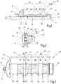
- Fig. 1 diagrammatically shows a first embodiment of a blind rivet which is denoted overall by 10.
- the blind rivet 10 has a rivet sleeve 12 and a pin 14.
- the rivet sleeve 12 has a sleeve head 16 for bearing against a visible-side workpiece surface and a sleeve shank 18 which adjoins the former and is formed in one piece with it.
- the sleeve shank 18 has a blind-side end 20 with an end side 22 which points away from the sleeve head 16.
- the rivet sleeve 12 has a through hole 24.
- the pin 14 is introduced into the through hole 24, to be precise from the blind-side end 20, with the result that a pin head 26 of the pin 14 bears against the end side 22.
- the pin 14 has a predetermined break point 28.
- the sleeve shank 18 has a primary region 30 and a secondary region 32, the primary region 30 being adjacent to the blind-side end 20, and the secondary region 32 being adjacent to the sleeve head 16.
- the primary region 30 contains a first forming section 34 and a second forming section 36, a first intermediate section 38 being formed between the first forming section 34 and the second forming section 36.
- the secondary region 32 has a third forming section 40, a second intermediate section 42 being formed between the third forming section 40 and the second forming section 36.
- the forming sections 34, 36, 40 can be formed in each case by embossed portions on the outer circumference of the sleeve shank 18, which embossed portions are, for example, of conical configuration.
- the first and the second forming section 34, 36 are of conical configuration such that their diameter increases towards the first intermediate section 38.
- a circumferential face shown diagrammatically in Fig. 1
- the blind rivet 10 In order to set the blind rivet 10, it is first of all introduced with the pin head 26 at the front through premanufactured holes in one or two workpieces, until an underside of the sleeve head 16 bears against a visible-side workpiece surface.
- the sleeve head 16 is subsequently fixed, for example by a holding force H.
- a setting force F is subsequently exerted on the pin 14 by means of a rivet gun.
- the sleeve shank 18 is deformed in such a way that a blind head is formed which bears against the blind-side workpiece surface, to be precise by the first intermediate section 38 or by the second intermediate section 42.
- the setting force F is then increased further, until the workpieces bear against one another and finally the pin 14 breaks in the region of the predetermined break point 28.
- the pin in the region of the pin head and in the region of the pin shank adjacent to the pin head can be configured similarly to that described in document WO 2009/098431 A1 ; reference is made here to the full scope of the disclosure contents of the said document.
- Fig. 2 shows a workpiece arrangement 50 which is finished by means of the blind rivet 10 and has a first workpiece 52 with a visible-side workpiece surface 53 and a second workpiece 54 with a blind-side workpiece surface 55.
- the two workpieces 52, 54 are relatively thin, with the result that a relatively small clamping thickness K is set up for the blind rivet 10. If two workpieces with a relatively great clamping thickness K are connected by means of the blind rivet 10, substantially only a first blind head 56 is formed by the first intermediate section 38, the second intermediate section 42 not being radially widened or being radially widened only to a small extent. In this embodiment, only the first blind head 56 then bears against the blind-side workpiece surface 55.
- FIG. 2 shows a workpiece arrangement with a relatively small clamping thickness K.
- first of all the first blind head 56 has been formed by the first intermediate section 38 during the setting operation.
- a second blind head 58 has then been formed on the basis of the second intermediate section 42, which second blind head 58 finally bears against the blind-side workpiece surface 55.
- the blind heads migrate in the axial direction during the setting operation, with the result that the workpieces 52, 54 are drawn against one another and are clamped axially against one another before the pin 14 breaks.
- FIG. 3 to 9 show alternative embodiments of blind rivets which are likewise configured as multiple-region rivets and, depending on the clamping thickness, form either only the first blind head 56 or both the first and the second blind head 56, 58.
- the blind rivets described in the following text correspond with regard to construction and function in general to the blind rivet 10 of Fig. 1 . Identical elements are therefore labelled by identical reference numerals. The differences will be essentially explained in the following text.
- Fig. 3 shows a further embodiment of a blind rivet 10, in which a fourth forming section 62 is configured in addition to the third forming section 40.
- the fourth forming section 62 is axially adjacent to the second forming section 36, it also being possible, however, for a web to be set up between them.
- the second intermediate section 42 lies in the axial direction between the third forming section 40 and the fourth forming section 62.
- the deformation behaviour of the second intermediate section 42 can be set more precisely.
- Fig. 3 shows various dimensions. It is thus shown that the first forming section 34 has an axial length L1.
- the second forming section 36 has an axial length L2.
- the third forming section 40 has an axial length L3.
- the fourth forming section 62 has a length L4.
- the first intermediate section 38 has an axial length L5.
- the second intermediate section 42 has an axial length L6.
- the lengths L1, L2, L3, L4 are approximately identically long.
- the axial length L5 of the first intermediate section 38 is greater, however, than the axial length L6 of the second intermediate section 42, at least one and a half times as great, preferably at least twice as great. In particular, it can hold that: L6 ⁇ 2.5 ⁇ L5.
- the first forming section 34 has a diameter D1 on the blind side and a diameter D2 on the visible side. Accordingly, the second forming section 36 has a diameter D3 on the visible side and a diameter D4 on the blind side.
- the third forming section 40 has a diameter D5 on the visible side and a diameter D6 on the blind side.
- the fourth forming section has the diameter D3 on the blind side and a diameter D7 on the visible side.
- the diameters D1, D3, D5 are identical and in each case smaller than the diameters D2, D4, D6, D7. In one embodiment, these last-mentioned diameters are also identical. As long as a web is provided between the second forming section 36 and the forming section 62, the diameters D1, D3 can also be greater than the diameter D5 and a corresponding diameter (for example D8, not shown) of the fourth forming section 62.
- FIG. 4 A blind rivet with a web of this type between the second and the fourth forming section 36, 62 is shown, for example, in Fig. 4.
- Figures 4 to 6 show how this blind rivet is deformed during setting, in order to fix two workpieces 52, 54 with a relatively great clamping thickness K MAX to one another.
- Fig. 4 shows an initial state.
- the workpieces 52, 54 are spaced apart from one another, and the blind rivet 10 protrudes beyond the second workpiece 54 to such an extent that the first intermediate section 38 likewise protrudes on the blind side with respect to the second workpiece 54.
- the setting force F As a result of application of the setting force F, first of all the first intermediate section 38 is deformed, as is shown in Fig. 5 . More precisely, the first intermediate section 38 is widened radially. As a result of further application of a setting force, the widened first intermediate section 38 which is formed as a result (and forms a first blind head 56) migrates in the axial direction towards the sleeve head 16. As a result, a spacing B between the workpieces 52, 54 is overcome. In other words, the second workpiece 54 is tightened with respect to the first workpiece 52.
- the setting force F is so low that the second intermediate section 42 is not widened or is substantially not widened radially.
- the first blind head 56 passes into a position, in which the workpieces 52, 54 bear against one another, as is shown in Fig. 6 . As a result of the setting force F being increased, the pin 14 breaks, and the workpiece arrangement 50 is produced.
- Figures 7 to 9 show a similar sequence for forming a workpiece arrangement 50 with a small clamping thickness K MIN .
- the second intermediate section 42 lies on the blind side outside the workpieces 52, 54 which are spaced apart from one another by a spacing B.
- the axial setting force F is once again applied.
- first of all the first blind head 56 is formed by the first intermediate section 38.
- the first blind head 56 migrates in the axial direction, until the maximum material widening is reached ( Fig. 8 ).
- the second intermediate section 42 then begins to be widened radially and to migrate in the axial direction towards the sleeve head 16.
- the second workpiece 54 is drawn against the first workpiece 52.
- an axial prestress is set up between the two workpieces 52, 54, until the pin 14 breaks and a workpiece arrangement 50 is produced, as is shown in Fig. 9 .
- the second blind head 58 bears against the blind-side workpiece surface, in a similar manner as in the illustration of Fig. 2 .
- the first and the second blind head 56, 58 can be spaced apart from one another, but can also bear axially against one another, as is shown in Fig. 2 .
- Fig. 10 schematically shows a diagram of the profile of the setting force F plotted against the travel S of the pin 14.
- the profile for a relatively great clamping thickness K MAX is shown by a continuous line.
- the profile for a relatively small clamping thickness K MIN is shown by a dashed line.
- first travel section 72 in which the first intermediate section 38 is widened radially and migrates in the axial direction.
- first blind head 56 is widened radially to a maximum extent and the workpieces are drawn against one another, until the pin 14 breaks at the end of the travel section 74 with a great clamping thickness.
- an increase in the setting force F takes place after the maximum radial widening of the first blind head 56 in a third travel section 76, by way of which increase in the setting force F the second intermediate section 42 is widened radially and migrates in the axial direction, until finally the pin breaks at the end of the third travel section 76.
Landscapes
- Engineering & Computer Science (AREA)
- General Engineering & Computer Science (AREA)
- Mechanical Engineering (AREA)
- Insertion Pins And Rivets (AREA)
- Connection Of Plates (AREA)
Claims (8)
- Rivet aveugle (10) comportant un corps de rivet (12) et un clou (14), le corps de rivet (12) comportant une tête de corps (16) destinée à un contact avec une surface (53) d'une pièce côté visible et un tronc de corps (18) et un trou traversant (24), à travers lequel est guidé le clou (14), le clou (14) comportant une tête de clou (26) côté aveugle destinée à un contact dans la région d'une extrémité (20) côté aveugle du tronc de corps (18), et le tronc de corps (18) comportant une première section de formation (34) et une deuxième section de formation (36) qui est disposée de manière espacée axialement vis-à-vis de la première section de formation (34) et plus près de la tête de corps (16), une première section intermédiaire (38) étant formée entre les première et deuxième sections de formation, ladite première section intermédiaire (38) pouvant, lors de la pose du rivet aveugle, former une première tête aveugle (56) qui peut être formée à des points axialement différents afin d'établir différentes épaisseurs de fixation (K), le tronc de corps (18) comportant une troisième section de formation (40) qui est disposée de manière espacée axialement vis-à-vis de la deuxième section de formation (36) et plus près de la tête de corps (16), une seconde section intermédiaire (42) étant formée entre les deuxième et troisième sections de formation de telle sorte que, lors de la pose du rivet aveugle de façon à établir des épaisseurs de fixation relativement élevées (KMAX), la seconde section intermédiaire est disposée axialement entre la première tête aveugle (56), qui est formée par la première section intermédiaire (38), et la tête de corps (16) et, lors de la pose du rivet aveugle de façon à établir des épaisseurs de fixation relativement faibles (KMIN), forme une seconde tête aveugle (58), et le tronc de corps (18) comportant une quatrième section de formation (62) qui est disposée entre les deuxième et troisième sections de formation, la seconde section intermédiaire (42) étant formée entre la troisième section de formation (40) et la quatrième section de formation (62),
caractérisé en ce que
les troisième et quatrième sections de formation sont formées par des parties coniques dont le diamètre augmente en direction de la seconde section intermédiaire (42). - Rivet aveugle selon la revendication 1, caractérisé en ce que la troisième section de formation (40) est directement adjacente à la tête de corps (16).
- Rivet aveugle selon l'une des revendications 1 et 2, caractérisé en ce qu'au moins une des première et deuxième sections de formation (34, 36) est formée par une partie estampée sur la circonférence extérieure de la section de corps (18).
- Rivet aveugle selon la revendication 3, caractérisé en ce qu'une partie estampée qui forme la troisième ou la quatrième section de formation est radialement plus profonde qu'une partie estampée qui forme la première ou la deuxième section de formation.
- Rivet aveugle selon l'une des revendications 1 à 4, caractérisé en ce qu'au moins une des première et deuxième sections de formation (34, 36) est formée par une partie estampée conique.
- Rivet aveugle selon l'une des revendications 1 à 5, caractérisé en ce que la seconde section intermédiaire (42) est axialement plus courte que la première section intermédiaire (38).
- Rivet aveugle selon l'une des revendications 1 à 6, caractérisé en ce que le matériau du tronc de corps (18) dans la région de la seconde section intermédiaire (42) est plus dur que le matériau du tronc de corps (18) dans la région de la première section intermédiaire (38).
- Agencement de pièces (50) comportant une première pièce (52) et au moins une deuxième pièce (54) qui sont raccordées l'une à l'autre par un rivet aveugle (10) selon l'une des revendications 1 à 7.
Applications Claiming Priority (2)
| Application Number | Priority Date | Filing Date | Title |
|---|---|---|---|
| DE102011113362A DE102011113362A1 (de) | 2011-09-15 | 2011-09-15 | Blindniet und Werkstückanordnung |
| PCT/EP2012/065820 WO2013037581A1 (fr) | 2011-09-15 | 2012-08-13 | Agencement de rivet aveugle et de pièce |
Publications (2)
| Publication Number | Publication Date |
|---|---|
| EP2756199A1 EP2756199A1 (fr) | 2014-07-23 |
| EP2756199B1 true EP2756199B1 (fr) | 2017-07-26 |
Family
ID=46724391
Family Applications (1)
| Application Number | Title | Priority Date | Filing Date |
|---|---|---|---|
| EP12750578.2A Not-in-force EP2756199B1 (fr) | 2011-09-15 | 2012-08-13 | Agencement de rivet aveugle et de pièce |
Country Status (8)
| Country | Link |
|---|---|
| US (1) | US9062703B2 (fr) |
| EP (1) | EP2756199B1 (fr) |
| JP (1) | JP2014530327A (fr) |
| KR (1) | KR20140061427A (fr) |
| CN (1) | CN103797251B (fr) |
| DE (1) | DE102011113362A1 (fr) |
| TW (1) | TW201321615A (fr) |
| WO (1) | WO2013037581A1 (fr) |
Families Citing this family (9)
| Publication number | Priority date | Publication date | Assignee | Title |
|---|---|---|---|---|
| DE202011103327U1 (de) * | 2011-07-13 | 2012-10-24 | Brose Fahrzeugteile Gmbh & Co. Kommanditgesellschaft, Hallstadt | Baugruppe mit mindestens zwei aneinander fixierten Bauteilen |
| DE102014104024A1 (de) | 2014-03-24 | 2015-09-24 | Newfrey Llc | Niethülse, Blindniet und Blindniet-Setzverfahren |
| DE102015120278A1 (de) | 2015-11-24 | 2017-05-24 | Newfrey Llc | Blindnietanordnung und Blindnietverfahren |
| KR20190039711A (ko) | 2016-08-12 | 2019-04-15 | 일리노이즈 툴 워크스 인코포레이티드 | 리벳 파스너 조립체 |
| JP7010429B2 (ja) * | 2017-10-27 | 2022-01-26 | ポップリベット・ファスナー株式会社 | ブラインドボルト |
| DE102019101078A1 (de) | 2018-01-16 | 2019-07-18 | Illinois Tool Works Inc. | Niet-befestigungselementanordnung und verfahren zu ihrer verwendung |
| US11268557B2 (en) * | 2018-10-10 | 2022-03-08 | Illinois Tool Works Inc. | Rivet fastener assembly and method of use thereof |
| CN112303090A (zh) * | 2020-10-16 | 2021-02-02 | 黄冈格罗夫氢能汽车有限公司 | 一种燃料电池氢能汽车用于连接标准型材的加长铆螺柱 |
| JP7762134B2 (ja) * | 2022-12-01 | 2025-10-29 | 株式会社ニフコ | 留め具、および留め付け構造 |
Family Cites Families (16)
| Publication number | Priority date | Publication date | Assignee | Title |
|---|---|---|---|---|
| DE8430648U1 (de) * | 1985-01-17 | Alfred Honsel Nieten - und Metallwarenfabrik GmbH & Co, 5758 Fröndenberg | Blindniet für unterschiedlich dicke Klemmbereiche | |
| US2324142A (en) * | 1941-04-03 | 1943-07-13 | Rolyan Corp | Rivet and method of making same |
| IT1175797B (it) * | 1984-06-21 | 1987-07-15 | Oggionni Tac Riveting Syst Sas | Rivetto cieco,a strappo,provvisto di un corpo tubolare suscettibile di ritrarsi,per azione del mandrino,formando una o piu' espansioni circonferenziali,di ritegno dei pezzi da unire |
| GB8702155D0 (en) * | 1987-01-30 | 1987-03-04 | Avdel Ltd | Break-stem blind rivet |
| ES2101943T3 (es) * | 1992-03-10 | 1997-07-16 | Black & Decker Inc | Casquillo universal. |
| GB9205192D0 (en) * | 1992-03-10 | 1992-04-22 | Emhart Inc | Universal plug |
| DE4343171C2 (de) * | 1993-12-17 | 1996-08-08 | Gesipa Blindniettechnik | Blindniet und Verfahren zu seiner Herstellung |
| GB2288649A (en) | 1994-04-14 | 1995-10-25 | Avdel Systems Ltd | Blind rivet |
| DE29716899U1 (de) * | 1997-09-22 | 1997-11-27 | Avdel Verbindungselemente GmbH, 30851 Langenhagen | Dornbruchblindniet und Vorrichtung zu seiner Verarbeitung |
| GB2346943A (en) * | 1999-02-19 | 2000-08-23 | Emhart Inc | Blind rivet with circumferential grooves and axial ribs |
| US6854940B2 (en) * | 1999-12-08 | 2005-02-15 | Newfrey Llc | Closed-end blind rivet with a crimped shank and method of manufacture thereof |
| GB0031251D0 (en) * | 2000-12-21 | 2001-01-31 | Emhart Inc | Blind rivet |
| US7198444B2 (en) * | 2002-05-22 | 2007-04-03 | Newfrey Llc | Multi-grip blind rivet |
| US6719509B1 (en) * | 2002-10-04 | 2004-04-13 | Joker Ind Co Ltd | Expansion screw |
| US6761520B1 (en) * | 2003-05-09 | 2004-07-13 | Pem Management, Inc. | Clinch-type blind nut |
| GB0801996D0 (en) | 2008-02-04 | 2008-03-12 | Newfrey Llc | Variable grip blind rivet |
-
2011
- 2011-09-15 DE DE102011113362A patent/DE102011113362A1/de not_active Withdrawn
-
2012
- 2012-08-13 KR KR1020147005079A patent/KR20140061427A/ko not_active Ceased
- 2012-08-13 CN CN201280045115.1A patent/CN103797251B/zh not_active Expired - Fee Related
- 2012-08-13 JP JP2014530134A patent/JP2014530327A/ja active Pending
- 2012-08-13 WO PCT/EP2012/065820 patent/WO2013037581A1/fr not_active Ceased
- 2012-08-13 EP EP12750578.2A patent/EP2756199B1/fr not_active Not-in-force
- 2012-08-31 TW TW101131938A patent/TW201321615A/zh unknown
-
2014
- 2014-02-26 US US14/190,894 patent/US9062703B2/en active Active
Non-Patent Citations (1)
| Title |
|---|
| None * |
Also Published As
| Publication number | Publication date |
|---|---|
| KR20140061427A (ko) | 2014-05-21 |
| JP2014530327A (ja) | 2014-11-17 |
| WO2013037581A1 (fr) | 2013-03-21 |
| US20140186141A1 (en) | 2014-07-03 |
| EP2756199A1 (fr) | 2014-07-23 |
| US9062703B2 (en) | 2015-06-23 |
| CN103797251B (zh) | 2016-03-30 |
| TW201321615A (zh) | 2013-06-01 |
| CN103797251A (zh) | 2014-05-14 |
| DE102011113362A1 (de) | 2013-03-21 |
Similar Documents
| Publication | Publication Date | Title |
|---|---|---|
| EP2756199B1 (fr) | Agencement de rivet aveugle et de pièce | |
| US3000420A (en) | Nut with recesses to receive metal of the workpiece | |
| EP2885547B1 (fr) | Dispositif de rivet aveugle | |
| US4692076A (en) | Expansion dowel with anchored state indicator | |
| EP2872270B1 (fr) | Outil de rivetage à poinçon et procédé de rivetage à poinçon | |
| EP2647851B1 (fr) | Élément de fixation et son procédé d'installation | |
| AU2009306140B2 (en) | Blind fastener | |
| CA2351467C (fr) | Fixation aveugle | |
| US3657957A (en) | Rivet | |
| AU610044B2 (en) | Blind rivet | |
| EP2580485B1 (fr) | Rivet aveugle et ensemble de fixation avec un rivet aveugle | |
| CA2606569A1 (fr) | Element de rivet aveugle et utilisation | |
| JPS63199911A (ja) | 盲破断ステムリベット | |
| AU605732B2 (en) | Blind rivet | |
| EP1369601B1 (fr) | Rivet aveugle du typ effeuillent | |
| US9903403B2 (en) | Fastener and method of installing same | |
| EP1362191A1 (fr) | Rivet aveugle et procede d'assemblage | |
| US20140308090A1 (en) | Blind rivet nut | |
| US20100068001A1 (en) | Rivet | |
| KR20160114178A (ko) | 블라인드 리벳 배열 및 조인트 | |
| EP0766012B1 (fr) | Rivet aveugle | |
| WO2014178036A1 (fr) | Rivet aveugle | |
| CA2687145C (fr) | Procede pour fixer un element d'assemblage ou fonctionnel sur un materiau plat, assemblage rivete et element d'assemblage ou fonctionnel |
Legal Events
| Date | Code | Title | Description |
|---|---|---|---|
| PUAI | Public reference made under article 153(3) epc to a published international application that has entered the european phase |
Free format text: ORIGINAL CODE: 0009012 |
|
| 17P | Request for examination filed |
Effective date: 20140414 |
|
| AK | Designated contracting states |
Kind code of ref document: A1 Designated state(s): AL AT BE BG CH CY CZ DE DK EE ES FI FR GB GR HR HU IE IS IT LI LT LU LV MC MK MT NL NO PL PT RO RS SE SI SK SM TR |
|
| DAX | Request for extension of the european patent (deleted) | ||
| RAP1 | Party data changed (applicant data changed or rights of an application transferred) |
Owner name: NEWFREY LLC |
|
| 17Q | First examination report despatched |
Effective date: 20160812 |
|
| GRAP | Despatch of communication of intention to grant a patent |
Free format text: ORIGINAL CODE: EPIDOSNIGR1 |
|
| INTG | Intention to grant announced |
Effective date: 20170227 |
|
| GRAS | Grant fee paid |
Free format text: ORIGINAL CODE: EPIDOSNIGR3 |
|
| GRAA | (expected) grant |
Free format text: ORIGINAL CODE: 0009210 |
|
| AK | Designated contracting states |
Kind code of ref document: B1 Designated state(s): AL AT BE BG CH CY CZ DE DK EE ES FI FR GB GR HR HU IE IS IT LI LT LU LV MC MK MT NL NO PL PT RO RS SE SI SK SM TR |
|
| REG | Reference to a national code |
Ref country code: GB Ref legal event code: FG4D |
|
| REG | Reference to a national code |
Ref country code: CH Ref legal event code: EP |
|
| REG | Reference to a national code |
Ref country code: AT Ref legal event code: REF Ref document number: 912648 Country of ref document: AT Kind code of ref document: T Effective date: 20170815 |
|
| REG | Reference to a national code |
Ref country code: IE Ref legal event code: FG4D |
|
| REG | Reference to a national code |
Ref country code: FR Ref legal event code: PLFP Year of fee payment: 6 |
|
| REG | Reference to a national code |
Ref country code: DE Ref legal event code: R096 Ref document number: 602012035022 Country of ref document: DE |
|
| REG | Reference to a national code |
Ref country code: NL Ref legal event code: MP Effective date: 20170726 |
|
| REG | Reference to a national code |
Ref country code: LT Ref legal event code: MG4D |
|
| REG | Reference to a national code |
Ref country code: AT Ref legal event code: MK05 Ref document number: 912648 Country of ref document: AT Kind code of ref document: T Effective date: 20170726 |
|
| PG25 | Lapsed in a contracting state [announced via postgrant information from national office to epo] |
Ref country code: AT Free format text: LAPSE BECAUSE OF FAILURE TO SUBMIT A TRANSLATION OF THE DESCRIPTION OR TO PAY THE FEE WITHIN THE PRESCRIBED TIME-LIMIT Effective date: 20170726 Ref country code: NO Free format text: LAPSE BECAUSE OF FAILURE TO SUBMIT A TRANSLATION OF THE DESCRIPTION OR TO PAY THE FEE WITHIN THE PRESCRIBED TIME-LIMIT Effective date: 20171026 Ref country code: FI Free format text: LAPSE BECAUSE OF FAILURE TO SUBMIT A TRANSLATION OF THE DESCRIPTION OR TO PAY THE FEE WITHIN THE PRESCRIBED TIME-LIMIT Effective date: 20170726 Ref country code: HR Free format text: LAPSE BECAUSE OF FAILURE TO SUBMIT A TRANSLATION OF THE DESCRIPTION OR TO PAY THE FEE WITHIN THE PRESCRIBED TIME-LIMIT Effective date: 20170726 Ref country code: LT Free format text: LAPSE BECAUSE OF FAILURE TO SUBMIT A TRANSLATION OF THE DESCRIPTION OR TO PAY THE FEE WITHIN THE PRESCRIBED TIME-LIMIT Effective date: 20170726 Ref country code: NL Free format text: LAPSE BECAUSE OF FAILURE TO SUBMIT A TRANSLATION OF THE DESCRIPTION OR TO PAY THE FEE WITHIN THE PRESCRIBED TIME-LIMIT Effective date: 20170726 Ref country code: SE Free format text: LAPSE BECAUSE OF FAILURE TO SUBMIT A TRANSLATION OF THE DESCRIPTION OR TO PAY THE FEE WITHIN THE PRESCRIBED TIME-LIMIT Effective date: 20170726 |
|
| PG25 | Lapsed in a contracting state [announced via postgrant information from national office to epo] |
Ref country code: PL Free format text: LAPSE BECAUSE OF FAILURE TO SUBMIT A TRANSLATION OF THE DESCRIPTION OR TO PAY THE FEE WITHIN THE PRESCRIBED TIME-LIMIT Effective date: 20170726 Ref country code: LV Free format text: LAPSE BECAUSE OF FAILURE TO SUBMIT A TRANSLATION OF THE DESCRIPTION OR TO PAY THE FEE WITHIN THE PRESCRIBED TIME-LIMIT Effective date: 20170726 Ref country code: GR Free format text: LAPSE BECAUSE OF FAILURE TO SUBMIT A TRANSLATION OF THE DESCRIPTION OR TO PAY THE FEE WITHIN THE PRESCRIBED TIME-LIMIT Effective date: 20171027 Ref country code: RS Free format text: LAPSE BECAUSE OF FAILURE TO SUBMIT A TRANSLATION OF THE DESCRIPTION OR TO PAY THE FEE WITHIN THE PRESCRIBED TIME-LIMIT Effective date: 20170726 Ref country code: ES Free format text: LAPSE BECAUSE OF FAILURE TO SUBMIT A TRANSLATION OF THE DESCRIPTION OR TO PAY THE FEE WITHIN THE PRESCRIBED TIME-LIMIT Effective date: 20170726 Ref country code: BG Free format text: LAPSE BECAUSE OF FAILURE TO SUBMIT A TRANSLATION OF THE DESCRIPTION OR TO PAY THE FEE WITHIN THE PRESCRIBED TIME-LIMIT Effective date: 20171026 Ref country code: IS Free format text: LAPSE BECAUSE OF FAILURE TO SUBMIT A TRANSLATION OF THE DESCRIPTION OR TO PAY THE FEE WITHIN THE PRESCRIBED TIME-LIMIT Effective date: 20171126 |
|
| REG | Reference to a national code |
Ref country code: CH Ref legal event code: PL |
|
| PG25 | Lapsed in a contracting state [announced via postgrant information from national office to epo] |
Ref country code: RO Free format text: LAPSE BECAUSE OF FAILURE TO SUBMIT A TRANSLATION OF THE DESCRIPTION OR TO PAY THE FEE WITHIN THE PRESCRIBED TIME-LIMIT Effective date: 20170726 Ref country code: CZ Free format text: LAPSE BECAUSE OF FAILURE TO SUBMIT A TRANSLATION OF THE DESCRIPTION OR TO PAY THE FEE WITHIN THE PRESCRIBED TIME-LIMIT Effective date: 20170726 Ref country code: DK Free format text: LAPSE BECAUSE OF FAILURE TO SUBMIT A TRANSLATION OF THE DESCRIPTION OR TO PAY THE FEE WITHIN THE PRESCRIBED TIME-LIMIT Effective date: 20170726 Ref country code: LI Free format text: LAPSE BECAUSE OF NON-PAYMENT OF DUE FEES Effective date: 20170831 Ref country code: CH Free format text: LAPSE BECAUSE OF NON-PAYMENT OF DUE FEES Effective date: 20170831 Ref country code: MC Free format text: LAPSE BECAUSE OF FAILURE TO SUBMIT A TRANSLATION OF THE DESCRIPTION OR TO PAY THE FEE WITHIN THE PRESCRIBED TIME-LIMIT Effective date: 20170726 |
|
| REG | Reference to a national code |
Ref country code: DE Ref legal event code: R097 Ref document number: 602012035022 Country of ref document: DE |
|
| REG | Reference to a national code |
Ref country code: IE Ref legal event code: MM4A |
|
| PG25 | Lapsed in a contracting state [announced via postgrant information from national office to epo] |
Ref country code: SM Free format text: LAPSE BECAUSE OF FAILURE TO SUBMIT A TRANSLATION OF THE DESCRIPTION OR TO PAY THE FEE WITHIN THE PRESCRIBED TIME-LIMIT Effective date: 20170726 Ref country code: IT Free format text: LAPSE BECAUSE OF FAILURE TO SUBMIT A TRANSLATION OF THE DESCRIPTION OR TO PAY THE FEE WITHIN THE PRESCRIBED TIME-LIMIT Effective date: 20170726 Ref country code: SK Free format text: LAPSE BECAUSE OF FAILURE TO SUBMIT A TRANSLATION OF THE DESCRIPTION OR TO PAY THE FEE WITHIN THE PRESCRIBED TIME-LIMIT Effective date: 20170726 Ref country code: EE Free format text: LAPSE BECAUSE OF FAILURE TO SUBMIT A TRANSLATION OF THE DESCRIPTION OR TO PAY THE FEE WITHIN THE PRESCRIBED TIME-LIMIT Effective date: 20170726 |
|
| PLBE | No opposition filed within time limit |
Free format text: ORIGINAL CODE: 0009261 |
|
| STAA | Information on the status of an ep patent application or granted ep patent |
Free format text: STATUS: NO OPPOSITION FILED WITHIN TIME LIMIT |
|
| REG | Reference to a national code |
Ref country code: BE Ref legal event code: MM Effective date: 20170831 |
|
| PG25 | Lapsed in a contracting state [announced via postgrant information from national office to epo] |
Ref country code: LU Free format text: LAPSE BECAUSE OF NON-PAYMENT OF DUE FEES Effective date: 20170813 |
|
| 26N | No opposition filed |
Effective date: 20180430 |
|
| REG | Reference to a national code |
Ref country code: FR Ref legal event code: PLFP Year of fee payment: 7 |
|
| PG25 | Lapsed in a contracting state [announced via postgrant information from national office to epo] |
Ref country code: IE Free format text: LAPSE BECAUSE OF NON-PAYMENT OF DUE FEES Effective date: 20170813 |
|
| PG25 | Lapsed in a contracting state [announced via postgrant information from national office to epo] |
Ref country code: SI Free format text: LAPSE BECAUSE OF FAILURE TO SUBMIT A TRANSLATION OF THE DESCRIPTION OR TO PAY THE FEE WITHIN THE PRESCRIBED TIME-LIMIT Effective date: 20170726 Ref country code: BE Free format text: LAPSE BECAUSE OF NON-PAYMENT OF DUE FEES Effective date: 20170831 |
|
| PG25 | Lapsed in a contracting state [announced via postgrant information from national office to epo] |
Ref country code: MT Free format text: LAPSE BECAUSE OF NON-PAYMENT OF DUE FEES Effective date: 20170813 |
|
| PG25 | Lapsed in a contracting state [announced via postgrant information from national office to epo] |
Ref country code: HU Free format text: LAPSE BECAUSE OF FAILURE TO SUBMIT A TRANSLATION OF THE DESCRIPTION OR TO PAY THE FEE WITHIN THE PRESCRIBED TIME-LIMIT; INVALID AB INITIO Effective date: 20120813 |
|
| PG25 | Lapsed in a contracting state [announced via postgrant information from national office to epo] |
Ref country code: CY Free format text: LAPSE BECAUSE OF NON-PAYMENT OF DUE FEES Effective date: 20170726 |
|
| PG25 | Lapsed in a contracting state [announced via postgrant information from national office to epo] |
Ref country code: MK Free format text: LAPSE BECAUSE OF FAILURE TO SUBMIT A TRANSLATION OF THE DESCRIPTION OR TO PAY THE FEE WITHIN THE PRESCRIBED TIME-LIMIT Effective date: 20170726 |
|
| PG25 | Lapsed in a contracting state [announced via postgrant information from national office to epo] |
Ref country code: TR Free format text: LAPSE BECAUSE OF FAILURE TO SUBMIT A TRANSLATION OF THE DESCRIPTION OR TO PAY THE FEE WITHIN THE PRESCRIBED TIME-LIMIT Effective date: 20170726 |
|
| PG25 | Lapsed in a contracting state [announced via postgrant information from national office to epo] |
Ref country code: PT Free format text: LAPSE BECAUSE OF FAILURE TO SUBMIT A TRANSLATION OF THE DESCRIPTION OR TO PAY THE FEE WITHIN THE PRESCRIBED TIME-LIMIT Effective date: 20170726 |
|
| PG25 | Lapsed in a contracting state [announced via postgrant information from national office to epo] |
Ref country code: AL Free format text: LAPSE BECAUSE OF FAILURE TO SUBMIT A TRANSLATION OF THE DESCRIPTION OR TO PAY THE FEE WITHIN THE PRESCRIBED TIME-LIMIT Effective date: 20170726 |
|
| PGFP | Annual fee paid to national office [announced via postgrant information from national office to epo] |
Ref country code: GB Payment date: 20220623 Year of fee payment: 11 |
|
| PGFP | Annual fee paid to national office [announced via postgrant information from national office to epo] |
Ref country code: FR Payment date: 20220609 Year of fee payment: 11 |
|
| PGFP | Annual fee paid to national office [announced via postgrant information from national office to epo] |
Ref country code: DE Payment date: 20220608 Year of fee payment: 11 |
|
| P01 | Opt-out of the competence of the unified patent court (upc) registered |
Effective date: 20230912 |
|
| REG | Reference to a national code |
Ref country code: DE Ref legal event code: R119 Ref document number: 602012035022 Country of ref document: DE |
|
| GBPC | Gb: european patent ceased through non-payment of renewal fee |
Effective date: 20230813 |
|
| PG25 | Lapsed in a contracting state [announced via postgrant information from national office to epo] |
Ref country code: GB Free format text: LAPSE BECAUSE OF NON-PAYMENT OF DUE FEES Effective date: 20230813 |
|
| PG25 | Lapsed in a contracting state [announced via postgrant information from national office to epo] |
Ref country code: GB Free format text: LAPSE BECAUSE OF NON-PAYMENT OF DUE FEES Effective date: 20230813 Ref country code: FR Free format text: LAPSE BECAUSE OF NON-PAYMENT OF DUE FEES Effective date: 20230831 Ref country code: DE Free format text: LAPSE BECAUSE OF NON-PAYMENT OF DUE FEES Effective date: 20240301 |