EP2756582B1 - Machine électrique tournante - Google Patents
Machine électrique tournante Download PDFInfo
- Publication number
- EP2756582B1 EP2756582B1 EP12769988.2A EP12769988A EP2756582B1 EP 2756582 B1 EP2756582 B1 EP 2756582B1 EP 12769988 A EP12769988 A EP 12769988A EP 2756582 B1 EP2756582 B1 EP 2756582B1
- Authority
- EP
- European Patent Office
- Prior art keywords
- cooling
- end wall
- housing
- cooling fan
- wall
- Prior art date
- Legal status (The legal status is an assumption and is not a legal conclusion. Google has not performed a legal analysis and makes no representation as to the accuracy of the status listed.)
- Active
Links
Images



Classifications
-
- H—ELECTRICITY
- H02—GENERATION; CONVERSION OR DISTRIBUTION OF ELECTRIC POWER
- H02K—DYNAMO-ELECTRIC MACHINES
- H02K9/00—Arrangements for cooling or ventilating
- H02K9/14—Arrangements for cooling or ventilating wherein gaseous cooling medium circulates between the machine casing and a surrounding mantle
- H02K9/16—Arrangements for cooling or ventilating wherein gaseous cooling medium circulates between the machine casing and a surrounding mantle wherein the cooling medium circulates through ducts or tubes within the casing
-
- H—ELECTRICITY
- H02—GENERATION; CONVERSION OR DISTRIBUTION OF ELECTRIC POWER
- H02K—DYNAMO-ELECTRIC MACHINES
- H02K5/00—Casings; Enclosures; Supports
- H02K5/04—Casings or enclosures characterised by the shape, form or construction thereof
- H02K5/18—Casings or enclosures characterised by the shape, form or construction thereof with ribs or fins for improving heat transfer
-
- H—ELECTRICITY
- H02—GENERATION; CONVERSION OR DISTRIBUTION OF ELECTRIC POWER
- H02K—DYNAMO-ELECTRIC MACHINES
- H02K9/00—Arrangements for cooling or ventilating
- H02K9/08—Arrangements for cooling or ventilating by gaseous cooling medium circulating wholly within the machine casing
-
- H—ELECTRICITY
- H02—GENERATION; CONVERSION OR DISTRIBUTION OF ELECTRIC POWER
- H02K—DYNAMO-ELECTRIC MACHINES
- H02K9/00—Arrangements for cooling or ventilating
- H02K9/14—Arrangements for cooling or ventilating wherein gaseous cooling medium circulates between the machine casing and a surrounding mantle
-
- H—ELECTRICITY
- H02—GENERATION; CONVERSION OR DISTRIBUTION OF ELECTRIC POWER
- H02K—DYNAMO-ELECTRIC MACHINES
- H02K9/00—Arrangements for cooling or ventilating
- H02K9/22—Arrangements for cooling or ventilating by solid heat conducting material embedded in, or arranged in contact with, the stator or rotor, e.g. heat bridges
- H02K9/227—Heat sinks
Definitions
- the present invention relates according to the preamble of claim 1, a rotating electric machine having a stator arranged in a housing and a rotatably mounted about a shaft about a rotation axis rotor, wherein the housing has a peripheral wall and two axially opposite, as bearing flanges with pivot bearings for the Has shaft formed end walls, and wherein two cooling fan wheels are connected to the shaft, on the one hand within the housing, an inner, upon rotation within the housing an inner cooling air circuit generating cooling fan and on the other hand outside the housing an outer, upon rotation, a housing overflowing outer cooling air flow generating cooling fan, wherein the arranged on the side of the outer cooling fan first end wall on its outer cooling fan wheel facing outside an outer fin geometry and on its opposite I nnenseite has an inner fin geometry, wherein the outerdelmodalerrad is formed as a radial wheel with radial blades, wherein on the first end wall - whosederippengeometrie and thedelpresenterrad overlapping - a cap-
- rotary electric machine includes both a design as a generator and an embodiment as a motor.
- the document EP 1 768 234 A1 describes an electric machine, which is actually a motor in a fully enclosed and fan-cooled design.
- the innerdelmodalerrad on the outer cooling fan wheel facing side of the stator and the rotor is arranged so that the two cooling fan wheels are separated from each other via the one, first end wall of the housing.
- the EP 1 100 182 A1 discloses an electric motor cooled by a fan wheel having a housing with a shell wall having first and second ends.
- the housing also has a first and second partition wall, which are arranged at the respective end of the jacket wall and each receive bearings.
- an inner surface of the housing also has a plurality of pins and an outer surface of the housing a plurality of ribs.
- the motor also has a stator mounted in the housing and a rotor mounted within the stator.
- a first radial impeller is disposed on an outer side of the first partition wall and generates an airflow flowing over the fins.
- a second fan wheel is disposed on an inner side of the first partition wall and generates an air flow flowing through an inner baffle and over the inner pins.
- the engine of the EP 1 100 182 A1 also has a fan cover for the first, outer fan, which has an air inlet opening in a cap wall perpendicular to the axis of rotation.
- the fan cover and the first divider divert the airflow over the case so that it passes over the fins and the first divider Partition wall radially outwardly flows, is deflected and flows in the axial direction outside over the housing.
- the US 2004/0150270 A1 discloses a fully enclosed electric motor having an inner fan wheel made of aluminum for better heat dissipation. In addition, an adjoining the fan impeller connecting wall made of aluminum.
- the GB 2 283 371 A discloses a motor having a fan and a motor body attached to a housing.
- the housing has pins for heat dissipation, which are arranged below the fan wheel and around the fan wheel.
- the object of the present invention is to further improve the cooling and, in particular, the heat removal at the first end wall from the interior of the housing to the outside.
- the first end wall of the housing which is arranged on the side of the outer cooling fan wheel between the latter and the inner cooling air circuit, has a high heat conductivity of at least 100 ⁇ W m ⁇ K is formed and on its outer cooling fan facing the outer side an outer fin geometry and on its opposite inner side an inner fin geometry, wherein the outer fin geometry of the first end wall in a radially inner, covered by the outer cooling fan during rotation region of the first end wall of pin-like, axially in the vicinity of the cooling fan wheel projecting cooling approaches and in a radially outwardly adjacent to the rotation region of the outer cooling fan wheel portion of the first End wall of pin-like, axially towards the hood projecting cooling approaches and is formed in a radially outer region of the first end wall of wing-like axially and radially oriented rib projections, which lie in the inner transition region between the cap wall and the peripheral edge of the hood.
- the heat transfer between the inner cooling air circuit and the outer cooling air flow is significantly improved.
- the flow of air within the housing absorbs the internal heat and effectively delivers it via the inner fin geometry to the first end wall. Due to the high thermal conductivity of the end wall, the heat on the outer fin geometry effectively outward to the cooling air flow on, so that the heat is released very effectively to the environment.
- good thermal conductivity in the context of the invention means a thermal conductivity ⁇ of at least 100 W m ⁇ K . but in particular at least 150 W m ⁇ K ,
- at least the first, the two-sidedderippengeometrien end wall made of aluminum, in particular die-cast aluminum, wherein the term “aluminum” also includes an aluminum alloy, so that the thermal conductivity - depending on the alloy - in the range of 150 to 240 W m ⁇ K lies.
- the peripheral wall of the housing consists of a corresponding, good heat conducting material, in particular aluminum.
- the opposite second end wall can advantageously also be made of aluminum, so that an effective heat transfer via a metallic machine mount connected to the second end wall is also achieved in this area.
- a rotary electric machine 1 according to the invention - in one embodiment as a generator or motor - has a stator 4 arranged in a closed housing 2 and a rotor 10 rotatably mounted about a shaft 6 about a rotation axis 8.
- stator 4 arranged in a closed housing 2
- rotor 10 rotatably mounted about a shaft 6 about a rotation axis 8.
- these internal components of the machine 1 Fig. 2 and 3 as well as on Fig. 5 directed.
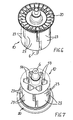
- the rotor 10 with the shaft 6 separately in 6 and 7 shown.
- the machine 1 Due to the closed housing 2, the machine 1 is completely encapsulated, so that it corresponds to a high IP protection class, in particular IP 54.
- the housing 2 consists of a rotor 10 and the stator 4 coaxially enclosing peripheral wall 12 and two axially opposite end walls 14 and 16. These end walls 14, 16 are formed as bearing flanges with pivot bearings 18 for the shaft 6.
- the pivot bearings 18 are ball bearings which enclose the shaft 6 and each seated in a receptacle of the respective end wall 14, 16.
- two cooling fan wheels 20 and 22 are connected to the shaft 6, on the one hand inside the housing 2 an internal cooling fan 20 and on the other hand outside the housing 2, an external cooling fan 22.
- the innerdelfreeerrad 20 generated during rotation within the housing 2 an inner cooling air circuit which in Fig. 2 and 3 is illustrated by dashed arrows A.
- the outer cooling fan wheel 22 generated during rotation of the housing 2 overflowing outer cooling air flow in Fig. 2 and 3 indicated by dashed arrows B.
- the electric machine 1 is formed as an internal rotor machine, wherein the rotor 10 is enclosed as an inner rotor of the stator 4 and rotates within the stator 4.
- the rotor 10 has permanent magnets 23 (see in particular FIG Fig. 5 ).
- the stator 4 consists of a stator core 24 and stator windings 26 designed as a laminated core.
- the first end wall 14 of the housing 2 with a high thermal conductivity of at least 100 ⁇ W m ⁇ K is formed and on its outside the cooling fan 22 outer side facing an outer fin geometry 28 and on its opposite inner side an inner fin geometry 30 has.
- the first end wall 14 is formed as a heat sink, which very effectively absorbs heat from the inner cooling air circuit A, leads to the outside and releases there to the outer cooling air flow B.
- the first end wall 14 is preferably made of aluminum, in particular as a one-piece aluminum die-cast part.
- the peripheral wall 12 and more preferably also the second end wall 16 made of aluminum. In the region of the second end wall 16, thereby an additional effective heat transfer via a metal machine mount (not shown) connected to the second end wall 16 can be achieved.
- the outer cooling fan 22 is formed as a radial wheel with radial blades 32, wherein the blades 32 lie with their blade surfaces in radially and axially aligned planes.
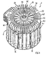
- Fig. 1 to 3 is here on the first end wall 14 - whose cooling rib geometry 28 and the cooling fan 22 overlapping - a cap-like hood 33 is placed, which consists of a vertical axis 8 to the rotation of the cap 8 wall 34 and a 34 extending from this cap wall, axial peripheral edge 36 of the first end wall 14th circumferentially overlaps in the axial direction.
- the frontal, perpendicular to the rotation axis 8 cap wall 34 has a central air inlet opening 38. This air inlet opening 38 may have an opening edge 38a extending in a nozzle-like manner to the outer cooling fan wheel 22.
- the outer cooling fan wheel 22 is formed in conjunction with the hood 33 and the outer cooling rib geometry 28 of the first housing end wall 14 such that ambient air is drawn axially from the outside when rotating through the air inlet opening 38 of the hood 33, this air radially fills the cooling rib geometry 28 flows through the outside and is deflected in the radially outer region via the hood 33 in an axial direction, finally, the housing peripheral wall 12 flows over the outside and thus passes back into the open. As a result, heat is dissipated to the outside.
- peripheral wall 12 of the housing 2 on the outside also has a cooling rib geometry 40, which preferably - at least predominantly - consists of elongated, radially projecting and axially extending cooling fins 42.
- the outer cooling rib geometry 28 of the first end wall 14 is concerned, it is according to the invention in a radially inner, covered by the outer cooling fan 22 during rotation region of the first end wall 14 of pin-like Refrigeration approaches 44 formed axially projecting into the vicinity of the plane defined by the facing edges of the blades 32 plane of rotation of the cooling fan wheel 22. It is a plurality of cooling lugs 44 which are arranged distributed in an annular surface area of the end wall 14.
- the outer cooling rib geometry 28 is formed in an annular surface region of the first end wall 14 which is likewise pin-shaped, but extends axially further towards the cap wall 34 of the hood 33 and thus extends longer cooling lugs 46 in a radially outward direction to the rotation region of the outer cooling fan wheel 22 ,
- These cooling lugs 46 are arranged distributed over the annular surface area with a large number.
- the outer cooling rib geometry 28 is formed in a radially outer, annular surface area of the first end wall 14 by a multiplicity of wing-like, axially and radially aligned rib projections 48.
- the rib projections 48 lie in the inner transition region between the cap wall 34 and the peripheral edge 36 of the hood 33.
- the approximately radially inwardly flowing air of the outer cooling air flow B flows radially between the rib projections 48, whereby a swirl of the flow is eliminated, and the hood 33 deflects the air flow from the radial direction in an axial direction.
- the cooling air in the axial or axially parallel direction can continue to flow over the peripheral wall 12 away.
- the inventive design of the outer cooling rib geometry 28 allows independent from the direction of rotation of the rotor 10 from the radially inner region to the outside, the wing-like ribs projections 48 for air flow and in cooperation with the hood 33 for air deflection as well as for eliminating a twist of the air flow B resulting from the rotation. Also, this effect of the rib projections 48 is independent of the direction of rotation due to their radial orientation.
- the inner cooling fan 20 may also be designed as a radial wheel. In the preferred embodiment, it is a diagonal wheel.
- the innerdelmodalerrad 20 causes during rotation that the inner cooling air circuit A by axial cooling channels 54 of the rotor 10, the innerderippengeometrie 30 of the first end wall 14, in particular between the stator core 24 and the stator windings 26 formed gaps of the stator 4 and preferably via a additional cooling rib geometry 56 runs on the inside of the second end wall 16, see in particular Fig. 3 ,
- the cooling rib geometry 56 of the second end wall 16 may consist of any desired cooling approaches, which may also act mechanically as stiffening ribs.
- the inner cooling rib geometry 30 of the first end wall 14 is at least partially formed by pin-like, axially projecting cooling lugs 58, whereby also independence from the direction of rotation is achieved.
- All cooling lugs 44, 46, 48, 58 of the or each end wall 14, 16 are formed with a tapering in the axial direction towards its free end cross-section that a production of the respective end wall 14, 16 as a one-piece molding, in particular as metal -Druckgussteil, with simple axial demoulding is possible.
- the wing-like rib projections 48 have an aspect ratio I: b which lies in the range between 1.5 and 6.0.
- the innerdelmodalerrad 20 on the first End wall 14 facing side of the rotor 10 is arranged. In principle, however, it can also lie on the other, the end wall 16 facing side of the rotor 10.
- the rotor 10 consists of two axially adjacent portions which are rotated with the permanent magnet 23 against each other in the circumferential direction by an angle of up to 20 °.
- the cooling channels 54 are arranged axially continuously in the radially inner, magnetically non-effective region of the rotor 10.
Landscapes
- Engineering & Computer Science (AREA)
- Power Engineering (AREA)
- Physics & Mathematics (AREA)
- Thermal Sciences (AREA)
- Motor Or Generator Cooling System (AREA)
- Motor Or Generator Frames (AREA)
Claims (10)
- Machine électrique tournante (1), comprenant un stator (4) disposé dans un boîtier (2) et un rotor (10) monté de manière à pouvoir tourner autour d'un axe de rotation (8) par l'intermédiaire d'un arbre (6), dans lequel le boîtier (2) présente une paroi périphérique (12) et deux parois frontales (14, 16) se faisant face axialement, réalisées sous la forme de supports de montage comprenant des coussinets de pivotement (18) pour l'arbre (6), et dans lequel deux roues de ventilateur de refroidissement (20, 22) sont reliées à l'arbre (6), à savoir d'une part, à l'intérieur du boîtier (2), une roue de ventilateur de refroidissement (20) intérieure produisant lors de la rotation à l'intérieur du boîtier (2) un circuit intérieur d'air de refroidissement (A) et d'autre part, à l'extérieur du boîtier (2), une roue de ventilateur de refroidissement (22) extérieure produisant lors de la rotation un écoulement d'air de refroidissement extérieur (B) inondant le boîtier (2), dans lequel la première paroi frontale (14) disposée sur le côté de la roue de ventilateur de refroidissement extérieure (22) présente, sur son côté extérieur tourné vers la roue de ventilateur de refroidissement extérieure (22), une forme géométrique extérieure de nervure de refroidissement (28), ainsi que, sur son côté intérieur opposé, une forme géométrique intérieure de nervure de refroidissement (30), dans lequel la roue de ventilateur de refroidissement extérieure (22) est réalisée sous la forme d'une roue radiale comprenant des pales (32) radiales, dans lequel un capot (33) de type capuchon est posé sur la première paroi frontale (14) - de manière à recouvrir la forme géométrique de nervure de refroidissement (28) de cette dernière et la roue de ventilateur de refroidissement (22), lequel capot présente, dans une paroi de capuchon (34) perpendiculaire par rapport à l'axe de rotation (8), une ouverture d'entrée d'air (38) centrée et qui entoure de manière périphérique la première paroi frontale (14) d'un bord périphérique (36) axial partant de la paroi de capuchon (34), dans lequel la roue de ventilateur de refroidissement extérieure (22) est réalisée en liaison avec le capot (33) de telle manière que lors de la rotation, de l'air aspiré axialement par l'ouverture d'entrée d'air (38) du capot (33) lors de la rotation traverse la forme géométrique de nervure de refroidissement extérieure (28) de manière radiale vers l'extérieur et qu'il est dévié dans la zone radialement extérieure par l'intermédiaire du capot (33) dans une direction axiale et inonde côté extérieur la paroi périphérique de boîtier (12),
caractérisée en ce que la première paroi frontale (14) est réalisée avec une conductivité thermique élevée d'au moins
- Machine électrique selon la revendication 1,
caractérisée en ce qu'au moins la première paroi frontale (14) du boîtier (2), de préférence également au moins la paroi périphérique (12), est constituée d'un matériau à bonne thermoconduction, en particulier d'aluminium. - Machine électrique selon la revendication 1 ou 2,
caractérisée en ce que la paroi périphérique (12) du boîtier (2) présente, côté extérieur une forme géométrique de nervure de refroidissement (40), qui est constituée de manière préférée au moins majoritairement de nervures de refroidissement (42) allongées, dépassant radialement et s'étendant axialement. - Machine électrique selon l'une quelconque des revendications 1 à 3,
caractérisée en ce que la première paroi frontale (14) présente, dans une zone de bord (50) extérieure faisant saillie radialement de la paroi périphérique (12) adjacente, des ouvertures d'air (52) pour l'écoulement d'air de refroidissement extérieur (B). - Machine électrique selon l'une quelconque des revendications 1 à 4,
caractérisée en ce que la roue de ventilateur de refroidissement intérieure (20) est réalisée sous la forme d'une roue radiale ou d'une roue diagonale de telle manière que le circuit d'air de refroidissement intérieur (A) s'étend à travers des canaux de refroidissement (54) axiaux du rotor (10), sur la forme géométrique de nervure de refroidissement intérieure (30) de la première paroi frontale (14), à travers en particulier des fentes, formées entre le noyau de stator (24) et des enroulements de stator (26), du stator (4), et de manière préférée sur une forme géométrique de nervure de refroidissement supplémentaire (56) sur le côté intérieur de la deuxième paroi frontale (16). - Machine électrique selon l'une quelconque des revendications 1 à 5,
caractérisée en ce que la forme géométrique de nervure de refroidissement intérieure (30) de la première paroi frontale (14) est formée au moins en partie par des épaulements de refroidissement (58) de type tige, dépassant axialement. - Machine électrique selon l'une quelconque des revendications 1 à 6,
caractérisée en ce que la roue de ventilateur de refroidissement intérieure (20) est disposée sur le côté, tourné vers la première paroi frontale (14), du rotor (10). - Machine électrique selon la revendication 1 ou 6,
caractérisée en ce que les épaulements de refroidissement (44, 46, 48, 58) de la/de chaque paroi frontale (14, 16) sont réalisés avec une section transversale se rétrécissant en direction de leur extrémité libre de sorte qu'il est possible de produire la paroi frontale (14 ; 16) sous la forme d'une pièce moulée, en particulier sous la forme d'une pièce moulée sous pression en métal, avec une simple déformation axiale. - Machine électrique selon la revendication 8,
caractérisée en ce que les épaulements de refroidissement (44, 46, 58) de type tige présentent, par rapport à leur section transversale, un rapport longueur-largeur (L/1) situé dans la plage comprise entre 0,8 et 1,5. - Machine électrique selon la revendication 1,
caractérisée en ce que les épaulements de nervure (48) de type ailette présentent, par rapport à leur section transversale, un rapport longueur-largeur (L/1) situé dans la plage comprise entre 1,5 et 6,0.
Applications Claiming Priority (2)
| Application Number | Priority Date | Filing Date | Title |
|---|---|---|---|
| DE102011053611A DE102011053611A1 (de) | 2011-09-14 | 2011-09-14 | Rotierende elektrische Maschine |
| PCT/EP2012/067775 WO2013037797A2 (fr) | 2011-09-14 | 2012-09-12 | Machine électrique tournante |
Publications (2)
| Publication Number | Publication Date |
|---|---|
| EP2756582A2 EP2756582A2 (fr) | 2014-07-23 |
| EP2756582B1 true EP2756582B1 (fr) | 2015-11-18 |
Family
ID=47008506
Family Applications (1)
| Application Number | Title | Priority Date | Filing Date |
|---|---|---|---|
| EP12769988.2A Active EP2756582B1 (fr) | 2011-09-14 | 2012-09-12 | Machine électrique tournante |
Country Status (5)
| Country | Link |
|---|---|
| US (1) | US9621010B2 (fr) |
| EP (1) | EP2756582B1 (fr) |
| CN (1) | CN103843231B (fr) |
| DE (1) | DE102011053611A1 (fr) |
| WO (1) | WO2013037797A2 (fr) |
Families Citing this family (37)
| Publication number | Priority date | Publication date | Assignee | Title |
|---|---|---|---|---|
| JP6260291B2 (ja) * | 2014-01-20 | 2018-01-17 | 日本電産株式会社 | モータ |
| DE202014101324U1 (de) * | 2014-03-21 | 2014-03-31 | Robert Bosch Gmbh | Elektrische Maschine mit einem Kühlkörper |
| DE102014009146A1 (de) * | 2014-06-20 | 2015-12-24 | Ziehl-Abegg Se | Elektromotor mit einem Rotor, einem Stator und einem Elektronikgehäuse sowie Lüfterrad für einen Elektromotor |
| DE102015207769A1 (de) * | 2015-04-28 | 2016-11-03 | Schaeffler Technologies AG & Co. KG | Elektrische Maschine mit Fluidkühlung an der Spulenwicklung |
| TWI575853B (zh) * | 2015-07-02 | 2017-03-21 | Wen-San Chou | 馬達之散熱構造 |
| TWI571034B (zh) * | 2015-07-28 | 2017-02-11 | 周文三 | 散熱馬達之結構 |
| DE102015221130A1 (de) * | 2015-10-29 | 2017-05-04 | Continental Automotive Gmbh | Elektrische Maschine für ein Kraftfahrzeug |
| DE102015118695A1 (de) * | 2015-11-02 | 2017-05-04 | Ebm-Papst Mulfingen Gmbh & Co. Kg | Elektromotor mit verbesserter Kühlung |
| CN107359730B (zh) * | 2016-05-10 | 2019-09-10 | Abb瑞士股份有限公司 | 电机的定子框架和电机 |
| KR101691515B1 (ko) * | 2016-07-11 | 2016-12-30 | (주)큰나무 | 공랭식 수직형 인라인 소수력발전장치 |
| KR101717024B1 (ko) * | 2016-10-13 | 2017-03-15 | (주)큰나무 | 공,수랭식 겸용 수직형 인라인 소수력발전장치 |
| WO2017195987A1 (fr) * | 2016-05-11 | 2017-11-16 | (주)큰나무 | Petit dispositif de production d'énergie hydroélectrique en ligne verticale |
| FR3057719B1 (fr) * | 2016-10-14 | 2022-12-16 | Ifp Energies Now | Machine electrique tournante fermee comportant un systeme de refroidissement interne par air |
| IT201600118253A1 (it) * | 2016-11-23 | 2018-05-23 | Nicotra Gebhardt S P A | Motore elettrico a rotore esterno |
| FR3059852B1 (fr) * | 2016-12-01 | 2019-08-23 | IFP Energies Nouvelles | Machine electrique tournante integrant un capteur de position magnetique. |
| CN106593919A (zh) * | 2016-12-19 | 2017-04-26 | 南京磁谷科技有限公司 | 一种300kw磁悬浮高速风机结构 |
| CN106487149B (zh) * | 2016-12-19 | 2023-12-26 | 南京磁谷科技股份有限公司 | 一种220kw磁悬浮高速电机双层散热式机壳结构 |
| CN106787441B (zh) * | 2016-12-19 | 2023-11-17 | 南京磁谷科技有限公司 | 一种220kW磁悬浮高速风机结构 |
| CN106787391B (zh) * | 2016-12-19 | 2023-11-17 | 南京磁谷科技有限公司 | 一种300kW磁悬浮高速电机混合式散热机壳结构 |
| KR101905306B1 (ko) * | 2017-02-15 | 2018-10-05 | 엘지전자 주식회사 | 모터 |
| JP7269663B2 (ja) | 2017-10-10 | 2023-05-09 | ゼロ イー テクノロジーズ,エルエルシー | 電気機械の冷却および安定化システムおよび方法 |
| CN109869770B (zh) * | 2017-12-04 | 2024-04-16 | 宁波方太厨具有限公司 | 一种灶用隔热罩及应用有该灶用隔热罩的灶具 |
| EP3553925A1 (fr) * | 2018-04-12 | 2019-10-16 | Siemens Aktiengesellschaft | Boîtier d'une machine à refroidissement optimisé |
| WO2020049617A1 (fr) | 2018-09-03 | 2020-03-12 | 本田技研工業株式会社 | Unité d'alimentation électrique, et machine de travail |
| WO2020202391A1 (fr) * | 2019-03-29 | 2020-10-08 | 本田技研工業株式会社 | Dispositif de moteur, unité d'alimentation électrique et machine de travail |
| CN109831053B (zh) * | 2019-03-29 | 2025-02-21 | 浙江铭振电子股份有限公司 | 外转子电机驱动器的散热结构、电机和离心风机 |
| CN112117855B (zh) | 2019-06-19 | 2023-07-11 | 台达电子工业股份有限公司 | 马达 |
| EP3996251B1 (fr) * | 2019-07-02 | 2024-08-21 | Honda Motor Co., Ltd. | Boîtier de machine électrique rotative |
| US11444507B2 (en) | 2019-10-04 | 2022-09-13 | Hamilton Sundstrand Corporation | Actuation motor with cooling fins |
| DE102019216845A1 (de) * | 2019-10-31 | 2021-05-06 | Robert Bosch Gmbh | Elektrische Maschine mit einer Kühlfunktion |
| FR3102716B1 (fr) * | 2019-11-06 | 2021-12-03 | Alstom Transp Tech | Dispositif de refroidissement d’un moteur électrique de traction d’un véhicule, ensemble de motorisation, véhicule et procédé de remplacement associés |
| KR102309981B1 (ko) * | 2020-01-09 | 2021-10-07 | 효성중공업 주식회사 | 고압 전동기용 프레임 핀 |
| DE102020100865A1 (de) | 2020-01-16 | 2021-07-22 | Ebm-Papst Mulfingen Gmbh & Co. Kg | Ventilator mit einem Außenläufermotor und Kühlkanal zur Kühlung der Motorelektronik und von Motorantriebskomponenten |
| US12470108B2 (en) * | 2021-02-25 | 2025-11-11 | Regal Beloit America, Inc. | Electric machine assembly having a rotatable terminal box |
| DE102021120673A1 (de) * | 2021-08-09 | 2023-02-09 | Ebm-Papst Mulfingen Gmbh & Co. Kg | Außenläufermotor mit einem Kühlrad zur Kühlung des Stators |
| JP2024049915A (ja) * | 2022-09-29 | 2024-04-10 | 本田技研工業株式会社 | 回転電機 |
| DE102023127750A1 (de) * | 2023-10-11 | 2025-04-17 | Mci (Mirror Controls International) Netherlands B.V. | Aktuator zur Verwendung in einem Kraftfahrzeug |
Family Cites Families (15)
| Publication number | Priority date | Publication date | Assignee | Title |
|---|---|---|---|---|
| GB276433A (en) * | 1926-05-28 | 1927-08-29 | Charles William Major | Improvements in and relating to the cooling and ventilation of dynamo electric machines |
| CH144107A (de) * | 1928-12-20 | 1930-12-15 | Bbc Brown Boveri & Cie | Elektrische Maschine mit über das Gehäuse von beiden Stirnseiten geführter Kühlluft. |
| CH147560A (de) * | 1929-03-29 | 1931-06-15 | Hinterseer Karoly | Ventilatorgekühlte elektrische Maschine. |
| GB754781A (en) * | 1954-06-23 | 1956-08-15 | English Electric Co Ltd | Improvements relating to dynamo-electric machines |
| DE1128023B (de) | 1960-08-03 | 1962-04-19 | Siemens Ag | Einrichtung zur Oberflaechenkuehlung von umlaufenden Maschinen, insbesondere Elektromotoren und Generatoren |
| US3518467A (en) * | 1968-11-04 | 1970-06-30 | Emerson Electric Co | Totally enclosed fan-cooled electric motor |
| FR2644642B1 (fr) | 1989-03-16 | 1995-04-14 | Cegelec Moteurs | Moteur electrique ferme a refroidissement par air et son procede de fabrication |
| GB2283371A (en) * | 1993-10-29 | 1995-05-03 | Horng Ching Shen | Motor having a heat dissipation configuration |
| EP1100182A1 (fr) | 1999-11-12 | 2001-05-16 | General Electric Company | Moteurs électriqes réfroidis par ventilateur avec dissipation thermique améliorée |
| CN1304203A (zh) * | 1999-11-30 | 2001-07-18 | 通用电气公司 | 增强散热的风扇冷却电马达 |
| KR100528586B1 (ko) * | 2002-11-25 | 2005-11-15 | 가부시끼가이샤 도시바 | 전폐 외선 냉각형 전동기 |
| WO2005124972A1 (fr) * | 2004-06-21 | 2005-12-29 | Mitsubishi Denki Kabushiki Kaisha | Moteur entièrement enfermé refroidi par ventilateur |
| WO2005124971A1 (fr) | 2004-06-21 | 2005-12-29 | Mitsubishi Denki Kabushiki Kaisha | Moteur de type à refroidissement par ventilateur entièrement protégé |
| JP4772298B2 (ja) | 2004-07-07 | 2011-09-14 | 株式会社東芝 | 車両駆動用全閉型電動機 |
| DE102009046192A1 (de) * | 2009-10-30 | 2011-05-05 | Robert Bosch Gmbh | Kraftfahrzeuggenerator, Lagerschild-Schaltungs-Einrichtung und Lagerschild mit optimierten Kühleigenschaften |
-
2011
- 2011-09-14 DE DE102011053611A patent/DE102011053611A1/de not_active Withdrawn
-
2012
- 2012-09-12 EP EP12769988.2A patent/EP2756582B1/fr active Active
- 2012-09-12 US US14/344,678 patent/US9621010B2/en active Active
- 2012-09-12 WO PCT/EP2012/067775 patent/WO2013037797A2/fr not_active Ceased
- 2012-09-12 CN CN201280045239.XA patent/CN103843231B/zh active Active
Also Published As
| Publication number | Publication date |
|---|---|
| CN103843231B (zh) | 2017-02-15 |
| US20140306559A1 (en) | 2014-10-16 |
| DE102011053611A1 (de) | 2013-03-14 |
| EP2756582A2 (fr) | 2014-07-23 |
| WO2013037797A3 (fr) | 2013-12-05 |
| US9621010B2 (en) | 2017-04-11 |
| WO2013037797A2 (fr) | 2013-03-21 |
| CN103843231A (zh) | 2014-06-04 |
Similar Documents
| Publication | Publication Date | Title |
|---|---|---|
| EP2756582B1 (fr) | Machine électrique tournante | |
| DE102006043169B4 (de) | Elektrische Maschine mit einem innengekühlten Läufer | |
| EP1722462B1 (fr) | Machine électrique | |
| DE69835123T2 (de) | Wechselstromgenrator mit verbesserten Mitteln zur Kühlung, insbesondere für ein Kraftfahrzeug | |
| EP3404808B1 (fr) | Dispositif formant moyeu de rotor, ventilateur électrique | |
| EP2897261B1 (fr) | Moteur électrique respirant | |
| WO2006013134A1 (fr) | Moteur electrique | |
| EP2566015B1 (fr) | Moteur électrique | |
| WO2013135465A1 (fr) | Moteur électrique | |
| DE2334637B2 (de) | Durchzugsbelüftete elektrische Maschine | |
| WO2016037859A2 (fr) | Générateur de centrale électrique | |
| WO2005064772A1 (fr) | Machine electrique | |
| WO2013007225A1 (fr) | Moteur électrique | |
| DE102015011863A1 (de) | Elektrische Maschine | |
| DE112016000819T5 (de) | Elektrische Rotationsmaschine, vorzugsweise für ein Hybridmotorfahrzeug | |
| DE3102333C2 (de) | Außenläufermotor | |
| DE102015204025A1 (de) | Elektrische Maschine mit einem Kühlkörper | |
| EP2591542B1 (fr) | Machine électrique | |
| DE112017000617T5 (de) | Elektrische Rotationsmaschine ausgestattet mit Kühlrippen | |
| DE102015219669A1 (de) | Elektrische Maschine mit einer Kühleinrichtung | |
| DE102017211346A1 (de) | Elektrische Maschine | |
| EP4135170A1 (fr) | Moteur électrique à refroidissement amélioré | |
| DE102004053326A1 (de) | Wechselstromgenerator | |
| DE112016002394T5 (de) | Rotierende elektrische maschine | |
| DE102019210609A1 (de) | Rotor und elektrische Maschine |
Legal Events
| Date | Code | Title | Description |
|---|---|---|---|
| PUAI | Public reference made under article 153(3) epc to a published international application that has entered the european phase |
Free format text: ORIGINAL CODE: 0009012 |
|
| 17P | Request for examination filed |
Effective date: 20140220 |
|
| AK | Designated contracting states |
Kind code of ref document: A2 Designated state(s): AL AT BE BG CH CY CZ DE DK EE ES FI FR GB GR HR HU IE IS IT LI LT LU LV MC MK MT NL NO PL PT RO RS SE SI SK SM TR |
|
| DAX | Request for extension of the european patent (deleted) | ||
| GRAP | Despatch of communication of intention to grant a patent |
Free format text: ORIGINAL CODE: EPIDOSNIGR1 |
|
| INTG | Intention to grant announced |
Effective date: 20150515 |
|
| RAP1 | Party data changed (applicant data changed or rights of an application transferred) |
Owner name: EBM-PAPST MULFINGEN GMBH & CO. KG |
|
| GRAS | Grant fee paid |
Free format text: ORIGINAL CODE: EPIDOSNIGR3 |
|
| GRAA | (expected) grant |
Free format text: ORIGINAL CODE: 0009210 |
|
| AK | Designated contracting states |
Kind code of ref document: B1 Designated state(s): AL AT BE BG CH CY CZ DE DK EE ES FI FR GB GR HR HU IE IS IT LI LT LU LV MC MK MT NL NO PL PT RO RS SE SI SK SM TR |
|
| REG | Reference to a national code |
Ref country code: GB Ref legal event code: FG4D Free format text: NOT ENGLISH |
|
| REG | Reference to a national code |
Ref country code: CH Ref legal event code: EP |
|
| REG | Reference to a national code |
Ref country code: AT Ref legal event code: REF Ref document number: 761984 Country of ref document: AT Kind code of ref document: T Effective date: 20151215 |
|
| REG | Reference to a national code |
Ref country code: IE Ref legal event code: FG4D Free format text: LANGUAGE OF EP DOCUMENT: GERMAN |
|
| REG | Reference to a national code |
Ref country code: DE Ref legal event code: R096 Ref document number: 502012005280 Country of ref document: DE |
|
| REG | Reference to a national code |
Ref country code: NL Ref legal event code: MP Effective date: 20160218 |
|
| REG | Reference to a national code |
Ref country code: LT Ref legal event code: MG4D |
|
| PG25 | Lapsed in a contracting state [announced via postgrant information from national office to epo] |
Ref country code: IT Free format text: LAPSE BECAUSE OF FAILURE TO SUBMIT A TRANSLATION OF THE DESCRIPTION OR TO PAY THE FEE WITHIN THE PRESCRIBED TIME-LIMIT Effective date: 20151118 Ref country code: HR Free format text: LAPSE BECAUSE OF FAILURE TO SUBMIT A TRANSLATION OF THE DESCRIPTION OR TO PAY THE FEE WITHIN THE PRESCRIBED TIME-LIMIT Effective date: 20151118 Ref country code: ES Free format text: LAPSE BECAUSE OF FAILURE TO SUBMIT A TRANSLATION OF THE DESCRIPTION OR TO PAY THE FEE WITHIN THE PRESCRIBED TIME-LIMIT Effective date: 20151118 Ref country code: NL Free format text: LAPSE BECAUSE OF FAILURE TO SUBMIT A TRANSLATION OF THE DESCRIPTION OR TO PAY THE FEE WITHIN THE PRESCRIBED TIME-LIMIT Effective date: 20151118 Ref country code: IS Free format text: LAPSE BECAUSE OF FAILURE TO SUBMIT A TRANSLATION OF THE DESCRIPTION OR TO PAY THE FEE WITHIN THE PRESCRIBED TIME-LIMIT Effective date: 20160318 Ref country code: LT Free format text: LAPSE BECAUSE OF FAILURE TO SUBMIT A TRANSLATION OF THE DESCRIPTION OR TO PAY THE FEE WITHIN THE PRESCRIBED TIME-LIMIT Effective date: 20151118 Ref country code: NO Free format text: LAPSE BECAUSE OF FAILURE TO SUBMIT A TRANSLATION OF THE DESCRIPTION OR TO PAY THE FEE WITHIN THE PRESCRIBED TIME-LIMIT Effective date: 20160218 |
|
| PG25 | Lapsed in a contracting state [announced via postgrant information from national office to epo] |
Ref country code: SE Free format text: LAPSE BECAUSE OF FAILURE TO SUBMIT A TRANSLATION OF THE DESCRIPTION OR TO PAY THE FEE WITHIN THE PRESCRIBED TIME-LIMIT Effective date: 20151118 Ref country code: LV Free format text: LAPSE BECAUSE OF FAILURE TO SUBMIT A TRANSLATION OF THE DESCRIPTION OR TO PAY THE FEE WITHIN THE PRESCRIBED TIME-LIMIT Effective date: 20151118 Ref country code: PT Free format text: LAPSE BECAUSE OF FAILURE TO SUBMIT A TRANSLATION OF THE DESCRIPTION OR TO PAY THE FEE WITHIN THE PRESCRIBED TIME-LIMIT Effective date: 20160318 Ref country code: FI Free format text: LAPSE BECAUSE OF FAILURE TO SUBMIT A TRANSLATION OF THE DESCRIPTION OR TO PAY THE FEE WITHIN THE PRESCRIBED TIME-LIMIT Effective date: 20151118 Ref country code: PL Free format text: LAPSE BECAUSE OF FAILURE TO SUBMIT A TRANSLATION OF THE DESCRIPTION OR TO PAY THE FEE WITHIN THE PRESCRIBED TIME-LIMIT Effective date: 20151118 Ref country code: GR Free format text: LAPSE BECAUSE OF FAILURE TO SUBMIT A TRANSLATION OF THE DESCRIPTION OR TO PAY THE FEE WITHIN THE PRESCRIBED TIME-LIMIT Effective date: 20160219 Ref country code: RS Free format text: LAPSE BECAUSE OF FAILURE TO SUBMIT A TRANSLATION OF THE DESCRIPTION OR TO PAY THE FEE WITHIN THE PRESCRIBED TIME-LIMIT Effective date: 20151118 |
|
| PG25 | Lapsed in a contracting state [announced via postgrant information from national office to epo] |
Ref country code: CZ Free format text: LAPSE BECAUSE OF FAILURE TO SUBMIT A TRANSLATION OF THE DESCRIPTION OR TO PAY THE FEE WITHIN THE PRESCRIBED TIME-LIMIT Effective date: 20151118 |
|
| REG | Reference to a national code |
Ref country code: DE Ref legal event code: R097 Ref document number: 502012005280 Country of ref document: DE |
|
| PG25 | Lapsed in a contracting state [announced via postgrant information from national office to epo] |
Ref country code: SM Free format text: LAPSE BECAUSE OF FAILURE TO SUBMIT A TRANSLATION OF THE DESCRIPTION OR TO PAY THE FEE WITHIN THE PRESCRIBED TIME-LIMIT Effective date: 20151118 Ref country code: SK Free format text: LAPSE BECAUSE OF FAILURE TO SUBMIT A TRANSLATION OF THE DESCRIPTION OR TO PAY THE FEE WITHIN THE PRESCRIBED TIME-LIMIT Effective date: 20151118 Ref country code: EE Free format text: LAPSE BECAUSE OF FAILURE TO SUBMIT A TRANSLATION OF THE DESCRIPTION OR TO PAY THE FEE WITHIN THE PRESCRIBED TIME-LIMIT Effective date: 20151118 Ref country code: RO Free format text: LAPSE BECAUSE OF FAILURE TO SUBMIT A TRANSLATION OF THE DESCRIPTION OR TO PAY THE FEE WITHIN THE PRESCRIBED TIME-LIMIT Effective date: 20151118 Ref country code: DK Free format text: LAPSE BECAUSE OF FAILURE TO SUBMIT A TRANSLATION OF THE DESCRIPTION OR TO PAY THE FEE WITHIN THE PRESCRIBED TIME-LIMIT Effective date: 20151118 |
|
| REG | Reference to a national code |
Ref country code: FR Ref legal event code: PLFP Year of fee payment: 5 |
|
| PLBE | No opposition filed within time limit |
Free format text: ORIGINAL CODE: 0009261 |
|
| STAA | Information on the status of an ep patent application or granted ep patent |
Free format text: STATUS: NO OPPOSITION FILED WITHIN TIME LIMIT |
|
| 26N | No opposition filed |
Effective date: 20160819 |
|
| PG25 | Lapsed in a contracting state [announced via postgrant information from national office to epo] |
Ref country code: SI Free format text: LAPSE BECAUSE OF FAILURE TO SUBMIT A TRANSLATION OF THE DESCRIPTION OR TO PAY THE FEE WITHIN THE PRESCRIBED TIME-LIMIT Effective date: 20151118 |
|
| PG25 | Lapsed in a contracting state [announced via postgrant information from national office to epo] |
Ref country code: BE Free format text: LAPSE BECAUSE OF NON-PAYMENT OF DUE FEES Effective date: 20160930 |
|
| PG25 | Lapsed in a contracting state [announced via postgrant information from national office to epo] |
Ref country code: MC Free format text: LAPSE BECAUSE OF FAILURE TO SUBMIT A TRANSLATION OF THE DESCRIPTION OR TO PAY THE FEE WITHIN THE PRESCRIBED TIME-LIMIT Effective date: 20151118 |
|
| REG | Reference to a national code |
Ref country code: CH Ref legal event code: PL |
|
| REG | Reference to a national code |
Ref country code: IE Ref legal event code: MM4A |
|
| PG25 | Lapsed in a contracting state [announced via postgrant information from national office to epo] |
Ref country code: CH Free format text: LAPSE BECAUSE OF NON-PAYMENT OF DUE FEES Effective date: 20160930 Ref country code: LI Free format text: LAPSE BECAUSE OF NON-PAYMENT OF DUE FEES Effective date: 20160930 Ref country code: IE Free format text: LAPSE BECAUSE OF NON-PAYMENT OF DUE FEES Effective date: 20160912 |
|
| PG25 | Lapsed in a contracting state [announced via postgrant information from national office to epo] |
Ref country code: LU Free format text: LAPSE BECAUSE OF NON-PAYMENT OF DUE FEES Effective date: 20160912 |
|
| REG | Reference to a national code |
Ref country code: FR Ref legal event code: PLFP Year of fee payment: 6 |
|
| REG | Reference to a national code |
Ref country code: BE Ref legal event code: MM Effective date: 20160930 |
|
| REG | Reference to a national code |
Ref country code: DE Ref legal event code: R082 Ref document number: 502012005280 Country of ref document: DE Representative=s name: PATENTANWAELTE STAEGER & SPERLING PARTNERSCHAF, DE |
|
| PG25 | Lapsed in a contracting state [announced via postgrant information from national office to epo] |
Ref country code: HU Free format text: LAPSE BECAUSE OF FAILURE TO SUBMIT A TRANSLATION OF THE DESCRIPTION OR TO PAY THE FEE WITHIN THE PRESCRIBED TIME-LIMIT; INVALID AB INITIO Effective date: 20120912 |
|
| PG25 | Lapsed in a contracting state [announced via postgrant information from national office to epo] |
Ref country code: MK Free format text: LAPSE BECAUSE OF FAILURE TO SUBMIT A TRANSLATION OF THE DESCRIPTION OR TO PAY THE FEE WITHIN THE PRESCRIBED TIME-LIMIT Effective date: 20151118 Ref country code: CY Free format text: LAPSE BECAUSE OF FAILURE TO SUBMIT A TRANSLATION OF THE DESCRIPTION OR TO PAY THE FEE WITHIN THE PRESCRIBED TIME-LIMIT Effective date: 20151118 Ref country code: MT Free format text: LAPSE BECAUSE OF FAILURE TO SUBMIT A TRANSLATION OF THE DESCRIPTION OR TO PAY THE FEE WITHIN THE PRESCRIBED TIME-LIMIT Effective date: 20151118 |
|
| PG25 | Lapsed in a contracting state [announced via postgrant information from national office to epo] |
Ref country code: BG Free format text: LAPSE BECAUSE OF FAILURE TO SUBMIT A TRANSLATION OF THE DESCRIPTION OR TO PAY THE FEE WITHIN THE PRESCRIBED TIME-LIMIT Effective date: 20151118 |
|
| REG | Reference to a national code |
Ref country code: FR Ref legal event code: PLFP Year of fee payment: 7 |
|
| PG25 | Lapsed in a contracting state [announced via postgrant information from national office to epo] |
Ref country code: AL Free format text: LAPSE BECAUSE OF FAILURE TO SUBMIT A TRANSLATION OF THE DESCRIPTION OR TO PAY THE FEE WITHIN THE PRESCRIBED TIME-LIMIT Effective date: 20151118 Ref country code: TR Free format text: LAPSE BECAUSE OF FAILURE TO SUBMIT A TRANSLATION OF THE DESCRIPTION OR TO PAY THE FEE WITHIN THE PRESCRIBED TIME-LIMIT Effective date: 20151118 |
|
| REG | Reference to a national code |
Ref country code: AT Ref legal event code: MM01 Ref document number: 761984 Country of ref document: AT Kind code of ref document: T Effective date: 20170912 |
|
| PG25 | Lapsed in a contracting state [announced via postgrant information from national office to epo] |
Ref country code: AT Free format text: LAPSE BECAUSE OF NON-PAYMENT OF DUE FEES Effective date: 20170912 |
|
| PGFP | Annual fee paid to national office [announced via postgrant information from national office to epo] |
Ref country code: DE Payment date: 20250919 Year of fee payment: 14 |
|
| PGFP | Annual fee paid to national office [announced via postgrant information from national office to epo] |
Ref country code: GB Payment date: 20250923 Year of fee payment: 14 |
|
| PGFP | Annual fee paid to national office [announced via postgrant information from national office to epo] |
Ref country code: FR Payment date: 20250926 Year of fee payment: 14 |