EP2756865B1 - Dispositif et procédé de détection de battement de fusion - Google Patents
Dispositif et procédé de détection de battement de fusion Download PDFInfo
- Publication number
- EP2756865B1 EP2756865B1 EP14151738.3A EP14151738A EP2756865B1 EP 2756865 B1 EP2756865 B1 EP 2756865B1 EP 14151738 A EP14151738 A EP 14151738A EP 2756865 B1 EP2756865 B1 EP 2756865B1
- Authority
- EP
- European Patent Office
- Prior art keywords
- fusion
- asci
- signal
- template
- beat
- Prior art date
- Legal status (The legal status is an assumption and is not a legal conclusion. Google has not performed a legal analysis and makes no representation as to the accuracy of the status listed.)
- Not-in-force
Links
Images



Classifications
-
- A—HUMAN NECESSITIES
- A61—MEDICAL OR VETERINARY SCIENCE; HYGIENE
- A61B—DIAGNOSIS; SURGERY; IDENTIFICATION
- A61B5/00—Measuring for diagnostic purposes; Identification of persons
- A61B5/24—Detecting, measuring or recording bioelectric or biomagnetic signals of the body or parts thereof
- A61B5/316—Modalities, i.e. specific diagnostic methods
- A61B5/318—Heart-related electrical modalities, e.g. electrocardiography [ECG]
- A61B5/346—Analysis of electrocardiograms
- A61B5/349—Detecting specific parameters of the electrocardiograph cycle
- A61B5/35—Detecting specific parameters of the electrocardiograph cycle by template matching
-
- A—HUMAN NECESSITIES
- A61—MEDICAL OR VETERINARY SCIENCE; HYGIENE
- A61N—ELECTROTHERAPY; MAGNETOTHERAPY; RADIATION THERAPY; ULTRASOUND THERAPY
- A61N1/00—Electrotherapy; Circuits therefor
- A61N1/18—Applying electric currents by contact electrodes
- A61N1/32—Applying electric currents by contact electrodes alternating or intermittent currents
- A61N1/36—Applying electric currents by contact electrodes alternating or intermittent currents for stimulation
- A61N1/362—Heart stimulators
- A61N1/37—Monitoring; Protecting
- A61N1/3702—Physiological parameters
-
- A—HUMAN NECESSITIES
- A61—MEDICAL OR VETERINARY SCIENCE; HYGIENE
- A61B—DIAGNOSIS; SURGERY; IDENTIFICATION
- A61B5/00—Measuring for diagnostic purposes; Identification of persons
- A61B5/24—Detecting, measuring or recording bioelectric or biomagnetic signals of the body or parts thereof
- A61B5/316—Modalities, i.e. specific diagnostic methods
- A61B5/318—Heart-related electrical modalities, e.g. electrocardiography [ECG]
- A61B5/346—Analysis of electrocardiograms
- A61B5/349—Detecting specific parameters of the electrocardiograph cycle
- A61B5/355—Detecting T-waves
-
- A—HUMAN NECESSITIES
- A61—MEDICAL OR VETERINARY SCIENCE; HYGIENE
- A61N—ELECTROTHERAPY; MAGNETOTHERAPY; RADIATION THERAPY; ULTRASOUND THERAPY
- A61N1/00—Electrotherapy; Circuits therefor
- A61N1/18—Applying electric currents by contact electrodes
- A61N1/32—Applying electric currents by contact electrodes alternating or intermittent currents
- A61N1/36—Applying electric currents by contact electrodes alternating or intermittent currents for stimulation
- A61N1/362—Heart stimulators
- A61N1/37—Monitoring; Protecting
- A61N1/371—Capture, i.e. successful stimulation
- A61N1/3712—Auto-capture, i.e. automatic adjustment of the stimulation threshold
Definitions
- the present invention generally relates to a heart monitoring and/or therapy device that is configured to detect fusion beats.
- Fusion beat represents the merging of two different cardiac excitation waves.
- fusion beat is often caused by the merging of intrinsic cardiac depolarization and the excitation wave generated by the pacing device that has generated a ventricular pace (VP).
- VP ventricular pace
- a ventricular pace can cause a stimulated ventricular depolarization of the heart muscle cells and thus a contraction of the myocardium if the strength of the ventricular pace is above a stimulation threshold.
- Such supra-threshold ventricular pace (ventricular stimulation pulse, VP) can capture the ventricular myocardium unless the cells of the ventricular myocardium are refractory.
- a sub-threshold ventricular pace will not cause capture.
- ventricular paces ventricular stimulation pulses
- ventricular stimulation pulses are only generated if the pacemaker does not detect a natural (intrinsic) depolarization and/or contraction of the myocardium within a certain time window.
- a ventricular pace is issued while there is also an intrinsic depolarization. The simultaneous occurrence of paced and intrinsic depolarization results in fusion beats.
- Fusion beat recognition is important for implantable cardiac devices for several reasons.
- cardiac stimulation that leads to fusion may represent a waste of battery power.
- fusion beat may disrupt the normal cardiac conduction and lead to inefficient myocardial contraction.
- the cardiac excitation after a pacing pulse may take the form that varies between a completely captured one (no intrinsic component) to a completely intrinsic one (no capture component), and the range can be viewed as a continuous spectrum of fusion with varying degrees.
- the clinical term pseudo-fusion generally refers to the superimposition of an ineffectual pacing spike on an intrinsic waveform.
- pseudo-fusion is viewed as a special case of fusion that is close to the intrinsic side of the spectrum.
- RV pacing statistics e.g. number and frequency of RV pacing
- Patient A who has 20% RV pacing may have lower risk of pacing-induced HF than patient B who has only 10% RV pacing - if the RV paces in patient A are mainly fusion beats dominated by intrinsic activity, whereas the majority of RV paces in patient B are fully captured beats.
- a common strategy is to maximize the percentage of BiV or LV pacing.
- the BiV or LV pacing percentage may not reflect the true effectiveness of CRT, because that metric could be inflated by fusion beats, which can be common during episodes of atrial fibrillation with intrinsic AV conduction.
- IEGM intracardiac electrogram
- fusion beat detection is performed based on template matching.
- specific features or feature statistics
- Capture (CAP) template and loss-of-capture (LOC) template are respectively created by overdrive pacing with supra-threshold amplitude and sub-threshold amplitude, respectively.
- a beat is identified as fusion if the extracted features of the post-pacing electrical response do not correspond to those from either CAP template or LOC template.
- the LOC response may show great variations due to multiple factors, for example, the amplitude-dependent pacing artefact, the timing of intrinsic activity after the LOC pace, etc. Therefore, a stable LOC template may not be available.
- the far-field signal present in the atrial channel is examined for evidence of a far-field R wave whenever the ventricular channel detects a LOC. If a far-field R wave is present, then fusion is confirmed. If a far-field R wave is absent, then LOC is confirmed.
- This method assumes (a) fusion beat is always accompanied by far-field R wave in atrial IEGM, and (b) far-field R wave is absent in case of LOC. However, either assumption may not be true. Depending on the degree of fusion and the sensitivity setting of the atrial channel, a fusion beat may not be accompanied by a far-field component in the atrial channel. Contrarily, after a non-capture ventricular pace, the intrinsic ventricular activity (either depolarization or repolarization) may be detected in the atrial channel.
- fusion or pseudo-fusion beat detection is performed in two sequential steps. After delivering a stimulus, the device first performs capture detection by examining the evoked response. If the device finds the stimulus did not result in capture, then it further uses morphology discrimination algorithm to compare one or more portions of the sensed IEGM to the corresponding portions of a template which represents the intrinsic waveform. If an adequate match exists between the compared portions, then the beat is classified as fusion and/or pseudo-fusion. According to this approach, no fusion or pseudo-fusion beat detection is performed if capture is detected after the pace. However, a captured pace can still result in fusion beat. That is, the device can capture the local myocardium and sense the evoked response, but the paced waveform can later fuse with the conducted intrinsic waveform. Therefore, this approach can misclassify a fusion beat to a captured beat.
- US 7,647,104 B1 discloses a method and apparatus for analysing IEGM waveforms.
- EP 1291038 A2 discloses an apparatus and a method for identifying fusion beats.
- US 2006/247693 A1 describes cardiac devices and methods which discriminate non-captured intrinsic beats during evoked response detection.
- Yet a further objective of this invention is to provide a heart monitoring and/or therapy device with a novel feature to quantify the burden of fusion to facilitate cardiac rhythm management.
- a heart monitoring or therapy device for detecting and quantifying fusion beats, wherein the device comprises
- the evaluation unit comprises or is connected to at least one template memory comprising at least a first template electrogram signal representing an intrinsic beat and a second template electrogram signal representing a captured (stimulated) beat.
- the evaluation unit is further configured to compare the recorded IEGM signal with both, the first and the second template electrogram signals and to determine two degrees of similarity for the recorded IEGM signal:
- the evaluation unit is further configured to calculate a fusion index FI from the at least two degrees of similarity.
- the heart monitoring or therapy device of the invention allows to quantitatively measure the degree of fusion.
- the device according to the invention provides for fusion beat quantification, that is to characterize the degree of fusion in a quantitative manner.
- This disclosure describes a novel means for fusion beat detection and for the first time describes a method for quantifying the degree of fusion after pacing.
- the present invention particularly relates to implantable cardiac devices including pacemakers, defibrillators and cardioverters, which stimulate cardiac tissue electrically to control the patient's heart rhythm.
- the device continuously monitors the IEGM signal, preferably from a far field sensing channel, on a beat-by-beat basis.
- the device also maintains two waveform templates, which are generated from the same far field sensing channel and represent the characteristic morphology of fully captured beat and purely intrinsic activation, respectively.
- the device senses the post-pace IEGM signal, and then compares it to the said two templates, respectively.
- the comparison is based on correlation analysis of the whole waveform, not limited to the expected evoked response window or any portion of the signal complex.
- the adaptive signed correlation index (ASCI) is used for the correlation analysis to measure the similarity between the sensed IEGM signal and the template signal.
- FI fusion index
- a method for detecting and quantifying fusion beats comprises the steps of:
- This invention provides a novel means of fusion beat detection and quantification. Compared to prior art, this solution has the following unique advantages:
- the invention compares IEGM morphology independently with both capture template and intrinsic template. Even if the device confirms the pacing captured the myocardium (e.g. the evoked response morphology has sufficient similarity to the capture template), fusion can still occur with a certain delay. Therefore, if the comparison of IEGM morphology with intrinsic template is dependent on the result of capture detection, false negatives will occur because many fusion beats may be misclassified as captured beats.
- the invention evaluates the morphological similarity between IEGM and templates based on correlation analysis of the whole waveform, not limited to specific morphological features (e.g. slope, peak amplitude, zero-crossing, etc.) or partial segment of the waveform. This leads to more accurate assessment of the morphological similarity between signals.
- specific morphological features e.g. slope, peak amplitude, zero-crossing, etc.
- the invention for the first time, discloses a method to quantify the degree of fusion.
- the proposed fusion index (FI) is a normalized value that ranges from 0 to 1, covering a continuous spectrum of pacing effect ranging from completely capture (no intrinsic component) to purely intrinsic (no capture component), and with varying degrees of fusion in between.
- this invention provides new statistical information (such as fusion beat percentage and fusion burden) which can be used to facilitate cardiac rhythm management. Therefore, this invention can lead to a novel diagnostic feature for cardiac rhythm management (CRM) products.
- CRM cardiac rhythm management
- the evaluation unit is configured to compare, for each cardiac cycle, the recorded IEGM signal to said first and said second template electrogram signal and to yield two adaptive signed correlation index (ASCI) values (ASCI ca p and ASCI int ), respectively.
- ASCI adaptive signed correlation index
- the evaluation unit is further configured to determine each adaptive signed correlation index ASCI ca p and ASCI; nt , respectively, by trichotomizing each recorded IEGM signal based on three signal subspaces, then calculating a signed correlation of the trichotomized vectors.
- the evaluation unit is configured to normalize the adaptive signed correlation index (ASCI) values in a range from -1 to +1.
- ASCI adaptive signed correlation index
- the evaluation unit is configured to determine an evidence of non-capture (EN), and an evidence of intrinsic (EI) and to calculate the fusion index (FI) therefrom.
- the fusion index preferably is a normalized index ranging from 0 to 1.
- the IEGM signal sensing channel is a far field sensing channel that is configured to show prominent ventricular components including QRS complexes and T waves on a beat-by-beat basis.
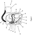
- stimulator 10 comprises a housing or case 12 and a header 14.
- the heart stimulator 10 is connected to three electrode leads, namely a right ventricular electrode lead 16, a right atrial electrode lead 18 and a left ventricular electrode lead 20.
- FIGS 1 and 2 illustrate the pacing system that includes a heart stimulator and the connected leads.
- the right atrial electrode lead 18 has a distal right atrial tip electrode 26 (RA-tip) at the distal end of right atrial electrode lead 18 and a proximal right atrial ring electrode 28 (RA-ring), as well as a superior vena cava coil electrode 36 (SVC-coil) that has a large surface area.
- RA-tip distal right atrial tip electrode 26
- RA-ring proximal right atrial ring electrode 28
- SVC-coil superior vena cava coil electrode 36
- the right ventricular electrode lead 16 has a distal right ventricular tip electrode 22 (RV-tip) at the distal end of right ventricular electrode lead 16 and a proximal right ventricular ring electrode 24 (RV-ring), as well as a right ventricular defibrillation coil electrode 34 (RV-coil) that has large surface area.
- RV-tip distal right ventricular tip electrode 22
- RV-ring proximal right ventricular ring electrode 24
- RV-coil right ventricular defibrillation coil electrode 34
- the left ventricular (LV) lead has a distal left ventricular tip electrode 30 (LV-tip) and a proximal left ventricular ring electrode 32 (LV-ring), as well as a defibrillation coil electrode 38 (LV-coil) that has a large surface area.
- the left ventricular electrode lead 20 is designed to pass trough the coronary sinus of heart 40.
- a typical electrode suitable for use with heart stimulator 10 is the electrode lead Corox+ UP/BB by the applicant.
- Each electrode and shock coil of electrode leads 16 to 20 is separately connected to an electric circuit enclosed by case 12 of heart stimulator 10 by way of electrical contacts of a plug (not shown) at the proximal end of each electrode lead 16 to 20 and corresponding contacts (not shown) in header 14 of heart stimulator 10.
- SVC shock coil 36 is connected to right atrial shock generator 68 that is controlled by a control unit 54 of heart stimulator 10.
- right ventricular shock coil 34 is connected to a right ventricular shock generator 52 that is connected to control unit 54 and left ventricular shock coil 38 is connected to a left ventricular shock generator 50 that is also connected to control unit 54.
- Right atrial tip electrode 26 and right atrial ring electrode 28 are both connected to a right atrial stimulation pulse generator 60 and a right atrial sensing stage 62 that in turn are both connected to control unit 54.
- Right atrial stimulation pulse generator 60 is adapted to generate atrial stimulation pulses of sufficient strength to cause an excitation of atrial myocardium by an electrical pulse delivered via right atrial tip electrode 26 and right atrial ring electrode 28.
- means are provided to adapt the right atrial stimulation pulse strength to the stimulation threshold in the right atrium.
- Right atrial sensing stage 58 is adapted to pick up myocardial potentials indicating an intrinsic atrial excitation that corresponds to a natural atrial contraction. By way of right atrial sensing stage 58, it is possible to stimulate the right atrium 44 of heart 40 in a demand mode wherein a right atrial stimulation pulse is inhibited if an intrinsic atrial event (intrinsic atrial excitation) is sensed by right atrial sensing stage 58 prior to expiration of an atrial escape interval.
- an intrinsic atrial event intrinsic atrial excitation
- right ventricular ring electrode 24 and right ventricular tip electrode 22 are connected to right ventricular stimulation pulse generator 56 and to a right ventricular sensing stage 58 that in turn are connected to control unit 54.
- right ventricular tip electrode 22 right ventricular ring electrode 24, right ventricular stimulation generator 56 and right ventricular sensing stage 58, right ventricular stimulation pulses can be delivered in a demand mode to the right ventricle 42 of heart 40.
- left ventricular tip electrode 30 and left ventricular ring electrode 32 are connected to the left ventricular stimulation pulse generator 64 and the left ventricular sensing stage 66 that in turn are both connected to control unit 52 and that allow for stimulating a left ventricle 46 of heart 40.
- Triggering and inhibition of delivery of stimulation pulses to the right atrium, the right ventricle or the left ventricle is controlled by control unit 54, in a manner known to the man skilled in the art.
- the timing that schedules delivery of stimulation pulses if needed is controlled by a number of intervals that at least partly may depend on a hemodynamic demand of a patient that is sensed by means of an activity sensor 72 that is connected to control unit 54.
- Activity sensor 72 allows for rate adaptive pacing, wherein a pacing rate (the rate of consecutive ventricular stimulation pulses for a duration of consecutive atrial stimulation pulses) depends on a physiological demand of a patient that is sensed by a way of activity sensor 72.
- a clock 82 allows recording of events and signals in association with time stamps that enable a synchronous evaluation of signals at a later point of time.
- a far-field right ventricular electrogram recording unit 74 and a far-field left-ventricular recording unit 76 are provided.
- the far-field right ventricular electrogram recording unit 74 is connected to a case electrode that is formed by at least an electrically conducting part of case 12 of the heart stimulator 10 and to the RV ring electrode 24.
- the far-field left ventricular recording unit 76 is also connected to the case electrode formed by a case 12 of heart stimulator 10 and to the left ventricular ring electrode 32.
- the far field RV and LV IEGM can also be recorded by connecting different electrodes or combination of different sensing vectors.
- the near-field electrogram in the right ventricle 42 is measured between the RV-tip electrode 22 and RV-ring electrode 24.
- the far-field electrogram in the right ventricle 38 is measured between the RV-coil electrode 34 and the device can 12.
- the far-field electrogram in the right ventricle 38 can be measured between the RV-ring electrode 24 and the device can 12.
- the near-field electrogram in the left ventricle 48 is measured between the LV-tip electrode 30 and LV-ring electrode 32.
- the far-field electrogram in left ventricle is measured between the LV-coil electrode 38 and the device can 12.
- the far-field electrogram in the left ventricle 48 can be measured between the LV-ring electrode 32 and the device can 12.
- the far-field electrogram in the right ventricle and the left ventricle are minimally filtered and have wide bandwidth, e.g., with lower corner frequency 4Hz and high corner frequency 128Hz, whereas the near-field electrograms in the right ventricle and the left ventricle are filtered with narrower bandwidth, e.g., with lower corner frequency 18Hz and high corner frequency 40Hz.
- right and left far-field ventricular recording units 74 and 76 comprise each a band pass filter with lower corner frequency (eg. 4Hz) and high corner frequency (eg. 128Hz).
- Right ventricular sensing stage 58 and left ventricular sensing stage 66 for picking up near-field electrograms in the right ventricle and the left ventricle each comprise band pass filters with narrower bandwidth, e.g. with lower corner frequency 18Hz and high corner frequency 40Hz.
- ventricular pacing is used as an example to illustrate the concept of fusion beat detection and quantification. It should be understood that the same concept is also applicable to atrial fusion beat detection and quantification.
- the device continuously monitors the IEGM signal, preferably from a far field sensing channel that shows prominent ventricular components (i.e. the QRS complex and the T wave) on a beat-by-beat basis.
- a far field sensing channel that shows prominent ventricular components (i.e. the QRS complex and the T wave) on a beat-by-beat basis.
- Figures 1 and 2 show a three-chamber ICD system that includes a device can, an RA lead with tip and ring electrodes and the SVC coil electrode, an RV lead with tip and ring electrode and the RV coil electrode, and an LV lead with tip and ring electrode and the LV coil electrode.
- Typical far field sensing vectors include, but are not limited to, RV ring - Can, LV ring - Can, RV coil - Can, LV coil - Can, SVC coil - RV coil, RA ring - RV ring, etc.
- Far-field IEGM can also be obtained by combining multiple sensing channels, for example, by forming a composite signal using the RV ring - Can channel and the LV ring - Can channel to measure the electrical activities from both RV and LV chambers, as shown in Figure 2 , far field electrogram composition unit 96.
- the far field sensing vectors used are RV ring - Can and LV ring - Can.
- the device For ventricular fusion beat detection and quantification, the device maintains two waveform templates in memory 80, which are generated from the same far field sensing channel and represent the characteristic morphology of fully captured beat and purely intrinsic activation, respectively.
- the capture and intrinsic templates can be created during the initial calibration phase. Specifically, to create the capture template, the device overdrives the ventricle (by programming sufficiently short AV delay to avoid ventricular fusion) with supra-threshold pacing amplitude for multiple cycles. The device then evaluates the IEGM signal after each pace. If the post-pace IEGM shows consistent waveform morphology over these multiple cycles, then their average waveform (note: all IEGM signals are aligned with the device generated pace marker) will be calculated and saved as the initial capture template. Preferably, the capture template covers both the depolarization phase (QRS complex) and part of the repolarization phase (T wave).
- QRS complex depolarization phase
- T wave part of the repolarization phase
- the device programs the device AV delay longer than the intrinsic AV conduction time to encourage antegrade ventricular depolarization.
- the device collects multiple cycles of the conducted ventricular IEGM signal, which are then aligned based on a predefined fiducial point, for example, the positive or negative peak, the maximum slope, etc., as known in the art. For each cycle, the IEGM segment in a fixed window relative to the fiducial point is selected. If the aligned IEGM segments over multiple cycles have similar morphology, then their average waveform is calculated and saved as the initial intrinsic template.
- the signal alignment can be achieved by locating and aligning with the central peak of the windowed absolute integral (WAI) signal.
- the WAI signal is obtained by transforming the original IEGM signal through a series of signal processing steps that include rectifying, windowing, and integrating.
- the WAI signal S out can be interpreted as the windowed power of the input signal S in .
- the central peak of the WAI signal represents the peak power of the input signal complex, and its location can be used to align the input IEGM signal.
- the template is fixed until the next template setup phase.
- the device can be programmed to enable template running update, that is, the template waveform can be continuously updated on a beat-by-beat basis.
- template running update that is, the template waveform can be continuously updated on a beat-by-beat basis.
- only captured beat that has similar morphology to the capture template is used to update the capture template
- only intrinsic beat that has similar morphology to the intrinsic template is used to update the intrinsic template.
- the template waveform can be dynamically adjusted to reflect possibly chronic change of the capture and/or intrinsic waveform morphology.
- Figure 3 shows (A) a capture template waveform and (B) an intrinsic template waveform generated by the device.
- TP positive threshold vector
- TN negative threshold vector
- ASCI adaptive signed correlation index
- the ASCI between two signals is calculated by trichotomizing each signal based on the three signal subspaces, then calculating the signed correlation of the trichotomized vectors.
- the ASCI is a normalized index ranging from -1 to +1.
- the ASCI between signals with similar morphology approaches 1 due to more concordant sample pairs, whereas the ASCI between signals with different morphology is lower or approaches -1 due to more nilcordant or discordant sample pairs.
- ASCI has the dual advantage of low computational complexity and sensitivity to amplitude difference, thus making it particularly useful in applications designed for low-power embedded systems such as the implantable cardiac devices.
- the device senses the post-pace far field IEGM signal and then compares it to the capture template and intrinsic template, respectively, by means of far field electrogram evaluation unit 98.
- the comparison is preferably based on ASCI, which measured the morphological similarity of the post-pace IEGM and two templates, respectively.
- ASCI the morphological comparison is based on the whole waveform, not limited to the expected evoked response window or any portion of the signal complex. Therefore, for each paced event, two ASCI values are calculated: ASCI cap and ASCI int , which measure the morphological similarity between post-pace IEGM and the capture template, and between post-pace IEGM and the intrinsic template, respectively.
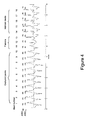
- Figure 4 shows a segment of far-field IEGM consisting of capture, fusion, and intrinsic beats.
- This segment shows 18 complete cardiac cycles, where each QRS complex is preceded by a ventricular pace (VP).
- the VP amplitude was gradually decreased from a supra-threshold value at the beginning to a sub-threshold value at the end of the segment.
- the first 10 cycles (beats 1-10) are captured beats with similar morphology to the capture template
- the last 5 cycles (beats 14-18) are intrinsic beats with similar morphology to the intrinsic template
- the middle 3 cycles (beats 11-13) are fusion beats with mixed but varying degrees of morphological features from both templates.
- the corresponding IEGM signal is compared to the pre-calibrated capture template and intrinsic template, yielding two ASCI values (ASCI cap and ASCI int ), respectively.
- the ASCI values (ASCI cap and ASCI int ) corresponding to the 18 beats shown in Figure 4 are further plotted in Figure 5 .
- the captured beats (1-10) are associated with high values of ASCI cap (all >0.75) and low values of ASCI int (all ⁇ 0)
- the intrinsic beats (14-18) are all associated with high values of ASCI int (all >0.75) and low values of ASCI cap (all ⁇ 0)
- the fusion beats (11-13) are associated with intermediate values of ASCI ca p and/or ASCIi nt .
- beats 11-13 are all fusion beats, the degree of fusion differs. As can be seen clearly in Figure 4 , fusion beat 11 has more dominant morphological features of capture waveform, and fusion beat 13 has more dominant morphological features of intrinsic waveform. On the other hand, fusion beat 12 has intermediate level of morphological features associated with both capture and intrinsic waveforms.
- a novel fusion index is constructed by the far field electrogram evaluation unit 98 from the two ASCI values (ASCI ca p and ASCI int ).
- the FI is consisted of two components: evidence of non-capture (EN), and evidence of intrinsic (EI).
- FI is a normalized index ranging from 0 to 1.
- This novel index offers a quantitative means to measure the degree of fusion.
- a fully captured beat has FI value close to 0 and an intrinsic beat has FI value close to 1.
- the intermediate value of FI indicates fusion.
- Smaller FI indicates the fusion beat has more capture component than intrinsic component. This occurs when the pacing induced wavefront has depolarized a relatively large portion of the ventricles before fusing with the intrinsic wavefront.
- larger FI implies that the fusion beat has more intrinsic component than capture component. This occurs when the intrinsic wavefront has depolarized a relatively large portion of the ventricles before fusing with the pacing induced wavefront.
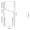
- Figure 6 plots the calculated FI values corresponding to the 18 cycles shown in Figure 4 .
- ⁇ is set to 0.25.
- the FI is zero for all captured beats (1-10), and is >0.90 for all intrinsic beats (14-18). Fusion beats (11, 12, 13) have intermediate FI values (resp. 0.15, 0.59, 0.85).
- fusion beat is detected if the associated FI value falls between the predefined upper and lower FI thresholds.
- the lower FI threshold defines a limit, below which the beat is classified as a fully captured beat
- the upper FI threshold defines a limit, above which the beat is classified as a purely intrinsic beat.
- the lower FI threshold is set to 0.25 and the lower FI threshold is set to 0.90.
- the upper and lower FI thresholds can be programmed by the user.
- new diagnostic metrics can be obtained by means of statistical analysis of the FI of all paces.
- One exemplary metric is the percentage of fusion beats, which is calculated as the ratio between the number of detected fusion beats and the total number of paces over a period of time (e.g. daily, monthly, etc).
- the fusion burden can be defined as the sum of FI values for all paced beats over a period of time (e.g., daily, monthly, etc).
- the fusion burden can be defined as a normalized metric by dividing the sum of FI values for all paced beats by the total number of paces over the period.
- a patient with an implanted CRT device may not respond to the CRT therapy if many LV paces result in fusion - despite nearly 100% BiV pacing.
- the new diagnostic metrics derived from fusion beat detection and fusion burden quantification can reveal the underlying problem, and may guide the physician to correct the issue and improve patient's outcome, for example, by programming a shorter device AV delay to minimize the fusion beats.
Landscapes
- Health & Medical Sciences (AREA)
- Life Sciences & Earth Sciences (AREA)
- Cardiology (AREA)
- Engineering & Computer Science (AREA)
- General Health & Medical Sciences (AREA)
- Biomedical Technology (AREA)
- Heart & Thoracic Surgery (AREA)
- Veterinary Medicine (AREA)
- Public Health (AREA)
- Animal Behavior & Ethology (AREA)
- Biophysics (AREA)
- Radiology & Medical Imaging (AREA)
- Nuclear Medicine, Radiotherapy & Molecular Imaging (AREA)
- Pathology (AREA)
- Surgery (AREA)
- Molecular Biology (AREA)
- Medical Informatics (AREA)
- Physics & Mathematics (AREA)
- Physiology (AREA)
- Electrotherapy Devices (AREA)
Claims (12)
- Dispositif de surveillance ou de thérapie cardiaque (10) pour la détection et la quantification de battements de fusion, ledit dispositif comprenant- un canal de détection du signal IEGM (96) qui délivre un signal IEGM présentant au moins des composantes ventriculaires importantes et- une unité d'évaluation (98) reliée de manière fonctionnelle audit canal de détection du signal IEGM et qui est configurée pour détecter les battements de fusion,où ladite unité d'évaluation (98) comprend ou est reliée à au moins une mémoire de modèles (80) comprenant au moins un premier signal d'un électrocardiogramme modèle représentant un battement intrinsèque et un second signal d'un électrocardiogramme modèle représentant un battement de capture, et
où ladite unité d'évaluation (98) est en outre configurée- pour comparer le signal IEGM enregistré avec les deux, ledit premier et ledit second signal de l'électrocardiogramme modèle et déterminer deux degrés de similarité pour le signal IEGM enregistré :- un premier degré de similarité reflétant les similarités entre le signal de l'électrocardiogramme enregistré et le premier signal de l'électrocardiogramme modèle et- un second degré de similarité reflétant les similarités entre le signal de l'électrocardiogramme enregistré et le second signal de l'électrocardiogramme modèle, où- deux valeurs (ASCIcap et ASCIint) de l'indice de corrélation positif ou négatif adaptatif (ASCI) sont utilisées pour mesurer les deux degrés de similarité, où- ladite unité d'évaluation (98) est en outre configurée pour calculer un indice de fusion FI à partir des deux valeurs ASCI, où ledit indice de fusion FI caractérise un degré de fusion de manière quantitative. - Dispositif selon la revendication 1, dans lequel ladite unité d'évaluation (98) est configurée pour déterminer chaque indice de corrélation positif ou négatif adaptatif ASCIcap et ASCIint, respectivement, en divisant en trois parties chacun des signaux IEGM enregistrés sur la base de trois sous-espaces du signal, puis en calculant une corrélation positive ou négative des vecteurs de la trichotomie.
- Dispositif selon la revendication 2, dans lequel ladite unité d'évaluation (98) est configurée pour normaliser les valeurs de l'indice de corrélation positif ou négatif adaptatif (ASCI) dans un intervalle entre - 1 et + 1.
- Dispositif selon la revendication 1, dans lequel ladite unité d'évaluation (98) est configurée pour déterminer un indice de non capture (EN), et un indice intrinsèque (EI) et calculer l'indice de fusion (FI) à partir de ceux-ci.
- Dispositif selon les revendications 2 et 4, dans lequel ladite unité d'évaluation (98) est configurée pour déterminer l'indice de non capture (EN) comme suit :

- Dispositif selon la revendication 5, dans lequel ladite tolérance Δ de capture prédéfinie est dans un intervalle entre 0 et 0,30.
- Dispositif selon les revendications 2 et 4, dans lequel ladite unité d'évaluation (98) est configurée pour déterminer ledit indice intrinsèque (EI) comme suit :

- Dispositif selon les revendications 5 et 7, dans lequel ladite unité d'évaluation (98) est configurée pour déterminer l'indice de fusion FI en tant que produit de EN et de EI, c'est-à-dire selon :

- Dispositif selon la revendication 1, dans lequel ladite unité d'évaluation (98) est en outre configurée pour calculer l'indice de fusion en tant qu'indice normé dans un intervalle entre 0 et 1.
- Dispositif selon la revendication 1, dans lequel le canal de détection du signal IEGM (96) est un canal de détection à champ lointain qui est configuré pour présenter les composantes ventriculaires importantes incluant les complexes QRS et les ondes T sur une base de battement par battement.
- Dispositif selon la revendication 1, dans lequel ledit dispositif est un stimulateur cardiaque implantable ou un défibrillateur automatique implantable ou une combinaison de ceux-ci.
- Procédé de détection et de quantification des battements de fusion, ledit procédé comprenant les étapes de :- délivrance d'un premier signal d'un électrocardiogramme modèle représentant un battement intrinsèque et d'un second signal d'un électrocardiogramme modèle représentant un battement de capture (stimulé)- comparaison du signal IEGM enregistré avec les deux, le premier et le second signal de l'électrocardiogramme modèle- détermination de deux degrés de similarité pour le signal IEGM enregistré, à savoir- un premier degré de similarité reflétant les similarités entre le signal de l'électrocardiogramme enregistré et le premier signal de l'électrocardiogramme modèle- un second degré de similarité reflétant les similarités entre le signal de l'électrocardiogramme enregistré et le second signal de l'électrocardiogramme modèle et où- deux valeurs (ASCIcap et ASCIint) de l'indice de corrélation positif ou négatif adaptatif (ASCI) sont utilisées pour mesurer les deux degrés de similarité,- calcul de l'indice de fusion FI à partir desdites deux valeurs de l'ASCI, où ledit indice de fusion FI caractérise le degré de fusion de manière quantitative.
Applications Claiming Priority (1)
| Application Number | Priority Date | Filing Date | Title |
|---|---|---|---|
| US201361754982P | 2013-01-22 | 2013-01-22 |
Publications (2)
| Publication Number | Publication Date |
|---|---|
| EP2756865A1 EP2756865A1 (fr) | 2014-07-23 |
| EP2756865B1 true EP2756865B1 (fr) | 2016-07-06 |
Family
ID=49956000
Family Applications (1)
| Application Number | Title | Priority Date | Filing Date |
|---|---|---|---|
| EP14151738.3A Not-in-force EP2756865B1 (fr) | 2013-01-22 | 2014-01-20 | Dispositif et procédé de détection de battement de fusion |
Country Status (2)
| Country | Link |
|---|---|
| US (1) | US9050013B2 (fr) |
| EP (1) | EP2756865B1 (fr) |
Families Citing this family (15)
| Publication number | Priority date | Publication date | Assignee | Title |
|---|---|---|---|---|
| EP3517029B1 (fr) | 2015-11-05 | 2021-01-06 | Sorin CRM SAS | Dispositif médical implantable actif comprenant des moyens de détections et de quantification des situations de fusion |
| US11027134B2 (en) | 2015-12-18 | 2021-06-08 | Sorin Crm Sas | Active implantable medical device such as a cardiac resynchroniser with dynamic adaptation of an atrioventricular delay depending on a detected and quantified degree of fusion |
| CN109414582B (zh) | 2016-06-27 | 2022-10-28 | 心脏起搏器股份公司 | 使用皮下感测p波进行再同步起搏管理的心脏治疗系统 |
| WO2018009392A1 (fr) | 2016-07-07 | 2018-01-11 | Cardiac Pacemakers, Inc. | Stimulateur cardiaque sans fil utilisant des mesures de pression pour la vérification de la capture de stimulation |
| US10870008B2 (en) | 2016-08-24 | 2020-12-22 | Cardiac Pacemakers, Inc. | Cardiac resynchronization using fusion promotion for timing management |
| WO2018039335A1 (fr) | 2016-08-24 | 2018-03-01 | Cardiac Pacemakers, Inc. | Thérapie intégrée de resynchronisation cardiaque à dispositifs multiples utilisant l'onde p pour stimuler la synchronisation. |
| US10758737B2 (en) | 2016-09-21 | 2020-09-01 | Cardiac Pacemakers, Inc. | Using sensor data from an intracardially implanted medical device to influence operation of an extracardially implantable cardioverter |
| EP3532161B1 (fr) | 2016-10-27 | 2023-08-30 | Cardiac Pacemakers, Inc. | Dispositif médical implantable à capteur de pression |
| US10463305B2 (en) | 2016-10-27 | 2019-11-05 | Cardiac Pacemakers, Inc. | Multi-device cardiac resynchronization therapy with timing enhancements |
| US10894163B2 (en) | 2016-11-21 | 2021-01-19 | Cardiac Pacemakers, Inc. | LCP based predictive timing for cardiac resynchronization |
| US11207532B2 (en) | 2017-01-04 | 2021-12-28 | Cardiac Pacemakers, Inc. | Dynamic sensing updates using postural input in a multiple device cardiac rhythm management system |
| WO2019036600A1 (fr) | 2017-08-18 | 2019-02-21 | Cardiac Pacemakers, Inc. | Dispositif médical implantable avec capteur de pression |
| US11284826B2 (en) * | 2017-09-06 | 2022-03-29 | Queen's University At Kingston | Methods for identifying wave break during atrial fibrillation |
| US10569091B2 (en) | 2017-12-21 | 2020-02-25 | Pacesetter, Inc. | Method and device for discrimination of left ventricular pseudo-fusion pacing |
| US11826575B2 (en) * | 2020-09-11 | 2023-11-28 | Pacesetter, Inc. | Method and device for controlling cardiac resynchronization therapy based on heart sounds |
Family Cites Families (15)
| Publication number | Priority date | Publication date | Assignee | Title |
|---|---|---|---|---|
| SE9903205D0 (sv) | 1999-09-09 | 1999-09-09 | Pacesetter Ab | Hjärtstimulator |
| SE0001113D0 (sv) * | 2000-03-29 | 2000-03-29 | Pacesetter Ab | Implantable heart stimulator |
| US6456881B1 (en) | 2000-08-02 | 2002-09-24 | Pacesetter, Inc. | System and method of identifying fusion for dual-chamber automatic capture stimulation device |
| US7006869B2 (en) | 2001-09-10 | 2006-02-28 | Pacesetter, Inc. | Method and device for enhanced capture tracking by discrimination of fusion beats |
| US6950704B1 (en) | 2001-11-01 | 2005-09-27 | Pacesetter, Inc. | Use of ER signal variability for fusion detection and response in ventricular and atrial autocapture algorithms |
| US7162301B2 (en) | 2002-12-31 | 2007-01-09 | Cardiac Pacemakers, Inc. | Method and system for detecting capture with cancellation of pacing artifact |
| US7328066B1 (en) | 2003-03-28 | 2008-02-05 | Pacesetter, Inc. | Implantable cardiac stimulation device, system and method that identifies and prevents impending arrhythmias of the atria |
| US6928326B1 (en) | 2003-03-31 | 2005-08-09 | Pacesetter, Inc. | Diagnosis of fusion or pseudofusion |
| US20060247693A1 (en) * | 2005-04-28 | 2006-11-02 | Yanting Dong | Non-captured intrinsic discrimination in cardiac pacing response classification |
| US7765004B2 (en) | 2005-04-28 | 2010-07-27 | Cardiac Pacemakers, Inc. | Methods and systems for managing fusion and noise in cardiac pacing response classification |
| US7529578B2 (en) | 2005-07-12 | 2009-05-05 | Cardiac Pacemakers, Inc. | Multi channel approach to capture verification |
| US7647104B1 (en) | 2006-10-13 | 2010-01-12 | Pacesetter, Inc. | Ischemia detection using paced depolarization integral and intracardiac electrogram template comparison |
| EP1995685A3 (fr) * | 2007-05-21 | 2012-08-01 | Biotronik CRM Patent AG | Dispositif médical pour surveiller un signal biologique |
| ATE503417T1 (de) | 2008-03-18 | 2011-04-15 | Biotronik Crm Patent Ag | Vorrichtung und computerlesbarer datenträger zur svt- und vt-klassifizierung |
| US8090434B2 (en) | 2008-03-18 | 2012-01-03 | Biotronik Crm Patent Ag | Device, method and computer-readable storage medium for enhanced sense event classification in implantable devices by means of morphology analysis |
-
2013
- 2013-12-03 US US14/095,736 patent/US9050013B2/en not_active Expired - Fee Related
-
2014
- 2014-01-20 EP EP14151738.3A patent/EP2756865B1/fr not_active Not-in-force
Also Published As
| Publication number | Publication date |
|---|---|
| US9050013B2 (en) | 2015-06-09 |
| EP2756865A1 (fr) | 2014-07-23 |
| US20140207013A1 (en) | 2014-07-24 |
Similar Documents
| Publication | Publication Date | Title |
|---|---|---|
| US9050013B2 (en) | Device and method for fusion beat detection | |
| EP1904168B1 (fr) | Procede pour produire un modele de signaux cardiaques au moyen d'un regroupement de formes d'onde | |
| US8831726B2 (en) | Cardiac response classification using multiple classification windows | |
| US8843199B2 (en) | Cardiac response classification using multisite sensing and pacing | |
| US8090434B2 (en) | Device, method and computer-readable storage medium for enhanced sense event classification in implantable devices by means of morphology analysis | |
| US7711424B2 (en) | Selection of cardiac signal features detected in multiple classification intervals for cardiac pacing response classification | |
| US9002454B2 (en) | Tracking pacing effectiveness based on waveform features | |
| US8831727B2 (en) | Methods and systems for managing fusion and noise in cardiac pacing response classification | |
| EP2136703B1 (fr) | Systemes et procedes de stimulation des caracteristiques des signaux cardiaques utilises dans la discrimination morphologique | |
| US7813791B1 (en) | Systems and methods for employing an FFT to distinguish R-waves from T-waves using an implantable medical device | |
| US20060247693A1 (en) | Non-captured intrinsic discrimination in cardiac pacing response classification | |
| US20080294217A1 (en) | Medical device for monitoring biological signals | |
| EP2103254A1 (fr) | Dispositif, procédé et support de stockage lisible par ordinateur pour classification SVT et VT | |
| US12161475B2 (en) | State-based atrial event detection | |
| US9014806B2 (en) | System and method for performing a capture test based on the analysis of a cardiac vectogram | |
| US8364264B2 (en) | Pacing interval adjustment for cardiac pacing response determination | |
| EP2767222A1 (fr) | Dispositif implantable de surveillance cardiaque |
Legal Events
| Date | Code | Title | Description |
|---|---|---|---|
| PUAI | Public reference made under article 153(3) epc to a published international application that has entered the european phase |
Free format text: ORIGINAL CODE: 0009012 |
|
| 17P | Request for examination filed |
Effective date: 20140120 |
|
| AK | Designated contracting states |
Kind code of ref document: A1 Designated state(s): AL AT BE BG CH CY CZ DE DK EE ES FI FR GB GR HR HU IE IS IT LI LT LU LV MC MK MT NL NO PL PT RO RS SE SI SK SM TR |
|
| AX | Request for extension of the european patent |
Extension state: BA ME |
|
| R17P | Request for examination filed (corrected) |
Effective date: 20141128 |
|
| RBV | Designated contracting states (corrected) |
Designated state(s): AL AT BE BG CH CY CZ DE DK EE ES FI FR GB GR HR HU IE IS IT LI LT LU LV MC MK MT NL NO PL PT RO RS SE SI SK SM TR |
|
| 17Q | First examination report despatched |
Effective date: 20150602 |
|
| GRAP | Despatch of communication of intention to grant a patent |
Free format text: ORIGINAL CODE: EPIDOSNIGR1 |
|
| INTG | Intention to grant announced |
Effective date: 20160209 |
|
| GRAS | Grant fee paid |
Free format text: ORIGINAL CODE: EPIDOSNIGR3 |
|
| GRAA | (expected) grant |
Free format text: ORIGINAL CODE: 0009210 |
|
| AK | Designated contracting states |
Kind code of ref document: B1 Designated state(s): AL AT BE BG CH CY CZ DE DK EE ES FI FR GB GR HR HU IE IS IT LI LT LU LV MC MK MT NL NO PL PT RO RS SE SI SK SM TR |
|
| REG | Reference to a national code |
Ref country code: GB Ref legal event code: FG4D |
|
| REG | Reference to a national code |
Ref country code: AT Ref legal event code: REF Ref document number: 810265 Country of ref document: AT Kind code of ref document: T Effective date: 20160715 Ref country code: CH Ref legal event code: EP |
|
| REG | Reference to a national code |
Ref country code: IE Ref legal event code: FG4D |
|
| REG | Reference to a national code |
Ref country code: DE Ref legal event code: R096 Ref document number: 602014002529 Country of ref document: DE |
|
| REG | Reference to a national code |
Ref country code: NL Ref legal event code: MP Effective date: 20160706 |
|
| REG | Reference to a national code |
Ref country code: LT Ref legal event code: MG4D |
|
| REG | Reference to a national code |
Ref country code: AT Ref legal event code: MK05 Ref document number: 810265 Country of ref document: AT Kind code of ref document: T Effective date: 20160706 |
|
| PG25 | Lapsed in a contracting state [announced via postgrant information from national office to epo] |
Ref country code: IT Free format text: LAPSE BECAUSE OF FAILURE TO SUBMIT A TRANSLATION OF THE DESCRIPTION OR TO PAY THE FEE WITHIN THE PRESCRIBED TIME-LIMIT Effective date: 20160706 Ref country code: LT Free format text: LAPSE BECAUSE OF FAILURE TO SUBMIT A TRANSLATION OF THE DESCRIPTION OR TO PAY THE FEE WITHIN THE PRESCRIBED TIME-LIMIT Effective date: 20160706 Ref country code: NO Free format text: LAPSE BECAUSE OF FAILURE TO SUBMIT A TRANSLATION OF THE DESCRIPTION OR TO PAY THE FEE WITHIN THE PRESCRIBED TIME-LIMIT Effective date: 20161006 Ref country code: NL Free format text: LAPSE BECAUSE OF FAILURE TO SUBMIT A TRANSLATION OF THE DESCRIPTION OR TO PAY THE FEE WITHIN THE PRESCRIBED TIME-LIMIT Effective date: 20160706 Ref country code: FI Free format text: LAPSE BECAUSE OF FAILURE TO SUBMIT A TRANSLATION OF THE DESCRIPTION OR TO PAY THE FEE WITHIN THE PRESCRIBED TIME-LIMIT Effective date: 20160706 Ref country code: RS Free format text: LAPSE BECAUSE OF FAILURE TO SUBMIT A TRANSLATION OF THE DESCRIPTION OR TO PAY THE FEE WITHIN THE PRESCRIBED TIME-LIMIT Effective date: 20160706 Ref country code: IS Free format text: LAPSE BECAUSE OF FAILURE TO SUBMIT A TRANSLATION OF THE DESCRIPTION OR TO PAY THE FEE WITHIN THE PRESCRIBED TIME-LIMIT Effective date: 20161106 Ref country code: HR Free format text: LAPSE BECAUSE OF FAILURE TO SUBMIT A TRANSLATION OF THE DESCRIPTION OR TO PAY THE FEE WITHIN THE PRESCRIBED TIME-LIMIT Effective date: 20160706 |
|
| PG25 | Lapsed in a contracting state [announced via postgrant information from national office to epo] |
Ref country code: GR Free format text: LAPSE BECAUSE OF FAILURE TO SUBMIT A TRANSLATION OF THE DESCRIPTION OR TO PAY THE FEE WITHIN THE PRESCRIBED TIME-LIMIT Effective date: 20161007 Ref country code: ES Free format text: LAPSE BECAUSE OF FAILURE TO SUBMIT A TRANSLATION OF THE DESCRIPTION OR TO PAY THE FEE WITHIN THE PRESCRIBED TIME-LIMIT Effective date: 20160706 Ref country code: AT Free format text: LAPSE BECAUSE OF FAILURE TO SUBMIT A TRANSLATION OF THE DESCRIPTION OR TO PAY THE FEE WITHIN THE PRESCRIBED TIME-LIMIT Effective date: 20160706 Ref country code: PL Free format text: LAPSE BECAUSE OF FAILURE TO SUBMIT A TRANSLATION OF THE DESCRIPTION OR TO PAY THE FEE WITHIN THE PRESCRIBED TIME-LIMIT Effective date: 20160706 Ref country code: BE Free format text: LAPSE BECAUSE OF FAILURE TO SUBMIT A TRANSLATION OF THE DESCRIPTION OR TO PAY THE FEE WITHIN THE PRESCRIBED TIME-LIMIT Effective date: 20160706 Ref country code: SE Free format text: LAPSE BECAUSE OF FAILURE TO SUBMIT A TRANSLATION OF THE DESCRIPTION OR TO PAY THE FEE WITHIN THE PRESCRIBED TIME-LIMIT Effective date: 20160706 Ref country code: PT Free format text: LAPSE BECAUSE OF FAILURE TO SUBMIT A TRANSLATION OF THE DESCRIPTION OR TO PAY THE FEE WITHIN THE PRESCRIBED TIME-LIMIT Effective date: 20161107 Ref country code: LV Free format text: LAPSE BECAUSE OF FAILURE TO SUBMIT A TRANSLATION OF THE DESCRIPTION OR TO PAY THE FEE WITHIN THE PRESCRIBED TIME-LIMIT Effective date: 20160706 |
|
| REG | Reference to a national code |
Ref country code: DE Ref legal event code: R097 Ref document number: 602014002529 Country of ref document: DE |
|
| PG25 | Lapsed in a contracting state [announced via postgrant information from national office to epo] |
Ref country code: RO Free format text: LAPSE BECAUSE OF FAILURE TO SUBMIT A TRANSLATION OF THE DESCRIPTION OR TO PAY THE FEE WITHIN THE PRESCRIBED TIME-LIMIT Effective date: 20160706 Ref country code: EE Free format text: LAPSE BECAUSE OF FAILURE TO SUBMIT A TRANSLATION OF THE DESCRIPTION OR TO PAY THE FEE WITHIN THE PRESCRIBED TIME-LIMIT Effective date: 20160706 |
|
| PLBE | No opposition filed within time limit |
Free format text: ORIGINAL CODE: 0009261 |
|
| STAA | Information on the status of an ep patent application or granted ep patent |
Free format text: STATUS: NO OPPOSITION FILED WITHIN TIME LIMIT |
|
| PG25 | Lapsed in a contracting state [announced via postgrant information from national office to epo] |
Ref country code: DK Free format text: LAPSE BECAUSE OF FAILURE TO SUBMIT A TRANSLATION OF THE DESCRIPTION OR TO PAY THE FEE WITHIN THE PRESCRIBED TIME-LIMIT Effective date: 20160706 Ref country code: SK Free format text: LAPSE BECAUSE OF FAILURE TO SUBMIT A TRANSLATION OF THE DESCRIPTION OR TO PAY THE FEE WITHIN THE PRESCRIBED TIME-LIMIT Effective date: 20160706 Ref country code: CZ Free format text: LAPSE BECAUSE OF FAILURE TO SUBMIT A TRANSLATION OF THE DESCRIPTION OR TO PAY THE FEE WITHIN THE PRESCRIBED TIME-LIMIT Effective date: 20160706 Ref country code: BG Free format text: LAPSE BECAUSE OF FAILURE TO SUBMIT A TRANSLATION OF THE DESCRIPTION OR TO PAY THE FEE WITHIN THE PRESCRIBED TIME-LIMIT Effective date: 20161006 Ref country code: SM Free format text: LAPSE BECAUSE OF FAILURE TO SUBMIT A TRANSLATION OF THE DESCRIPTION OR TO PAY THE FEE WITHIN THE PRESCRIBED TIME-LIMIT Effective date: 20160706 |
|
| 26N | No opposition filed |
Effective date: 20170407 |
|
| PG25 | Lapsed in a contracting state [announced via postgrant information from national office to epo] |
Ref country code: SI Free format text: LAPSE BECAUSE OF FAILURE TO SUBMIT A TRANSLATION OF THE DESCRIPTION OR TO PAY THE FEE WITHIN THE PRESCRIBED TIME-LIMIT Effective date: 20160706 |
|
| PG25 | Lapsed in a contracting state [announced via postgrant information from national office to epo] |
Ref country code: MC Free format text: LAPSE BECAUSE OF FAILURE TO SUBMIT A TRANSLATION OF THE DESCRIPTION OR TO PAY THE FEE WITHIN THE PRESCRIBED TIME-LIMIT Effective date: 20160706 |
|
| REG | Reference to a national code |
Ref country code: FR Ref legal event code: ST Effective date: 20170929 |
|
| PG25 | Lapsed in a contracting state [announced via postgrant information from national office to epo] |
Ref country code: FR Free format text: LAPSE BECAUSE OF NON-PAYMENT OF DUE FEES Effective date: 20170131 |
|
| PG25 | Lapsed in a contracting state [announced via postgrant information from national office to epo] |
Ref country code: LU Free format text: LAPSE BECAUSE OF NON-PAYMENT OF DUE FEES Effective date: 20170120 |
|
| GBPC | Gb: european patent ceased through non-payment of renewal fee |
Effective date: 20180120 |
|
| PG25 | Lapsed in a contracting state [announced via postgrant information from national office to epo] |
Ref country code: MT Free format text: LAPSE BECAUSE OF NON-PAYMENT OF DUE FEES Effective date: 20170120 |
|
| PG25 | Lapsed in a contracting state [announced via postgrant information from national office to epo] |
Ref country code: AL Free format text: LAPSE BECAUSE OF FAILURE TO SUBMIT A TRANSLATION OF THE DESCRIPTION OR TO PAY THE FEE WITHIN THE PRESCRIBED TIME-LIMIT Effective date: 20160706 |
|
| PG25 | Lapsed in a contracting state [announced via postgrant information from national office to epo] |
Ref country code: GB Free format text: LAPSE BECAUSE OF NON-PAYMENT OF DUE FEES Effective date: 20180120 |
|
| PG25 | Lapsed in a contracting state [announced via postgrant information from national office to epo] |
Ref country code: HU Free format text: LAPSE BECAUSE OF FAILURE TO SUBMIT A TRANSLATION OF THE DESCRIPTION OR TO PAY THE FEE WITHIN THE PRESCRIBED TIME-LIMIT; INVALID AB INITIO Effective date: 20140120 |
|
| PG25 | Lapsed in a contracting state [announced via postgrant information from national office to epo] |
Ref country code: CY Free format text: LAPSE BECAUSE OF NON-PAYMENT OF DUE FEES Effective date: 20160706 |
|
| PG25 | Lapsed in a contracting state [announced via postgrant information from national office to epo] |
Ref country code: MK Free format text: LAPSE BECAUSE OF FAILURE TO SUBMIT A TRANSLATION OF THE DESCRIPTION OR TO PAY THE FEE WITHIN THE PRESCRIBED TIME-LIMIT Effective date: 20160706 |
|
| PG25 | Lapsed in a contracting state [announced via postgrant information from national office to epo] |
Ref country code: TR Free format text: LAPSE BECAUSE OF FAILURE TO SUBMIT A TRANSLATION OF THE DESCRIPTION OR TO PAY THE FEE WITHIN THE PRESCRIBED TIME-LIMIT Effective date: 20160706 |
|
| PGFP | Annual fee paid to national office [announced via postgrant information from national office to epo] |
Ref country code: IE Payment date: 20220125 Year of fee payment: 9 Ref country code: DE Payment date: 20220124 Year of fee payment: 9 Ref country code: CH Payment date: 20220125 Year of fee payment: 9 |
|
| REG | Reference to a national code |
Ref country code: DE Ref legal event code: R119 Ref document number: 602014002529 Country of ref document: DE |
|
| REG | Reference to a national code |
Ref country code: CH Ref legal event code: PL |
|
| PG25 | Lapsed in a contracting state [announced via postgrant information from national office to epo] |
Ref country code: LI Free format text: LAPSE BECAUSE OF NON-PAYMENT OF DUE FEES Effective date: 20230131 Ref country code: DE Free format text: LAPSE BECAUSE OF NON-PAYMENT OF DUE FEES Effective date: 20230801 Ref country code: CH Free format text: LAPSE BECAUSE OF NON-PAYMENT OF DUE FEES Effective date: 20230131 |
|
| PG25 | Lapsed in a contracting state [announced via postgrant information from national office to epo] |
Ref country code: IE Free format text: LAPSE BECAUSE OF NON-PAYMENT OF DUE FEES Effective date: 20230120 |