EP2757005A2 - Procédé de retenue d'un véhicule automobile sur une pente - Google Patents
Procédé de retenue d'un véhicule automobile sur une pente Download PDFInfo
- Publication number
- EP2757005A2 EP2757005A2 EP14150960.4A EP14150960A EP2757005A2 EP 2757005 A2 EP2757005 A2 EP 2757005A2 EP 14150960 A EP14150960 A EP 14150960A EP 2757005 A2 EP2757005 A2 EP 2757005A2
- Authority
- EP
- European Patent Office
- Prior art keywords
- holding
- transmission
- combustion engine
- internal combustion
- clutch
- Prior art date
- Legal status (The legal status is an assumption and is not a legal conclusion. Google has not performed a legal analysis and makes no representation as to the accuracy of the status listed.)
- Granted
Links
Images


Classifications
-
- B—PERFORMING OPERATIONS; TRANSPORTING
- B60—VEHICLES IN GENERAL
- B60W—CONJOINT CONTROL OF VEHICLE SUB-UNITS OF DIFFERENT TYPE OR DIFFERENT FUNCTION; CONTROL SYSTEMS SPECIALLY ADAPTED FOR HYBRID VEHICLES; ROAD VEHICLE DRIVE CONTROL SYSTEMS FOR PURPOSES NOT RELATED TO THE CONTROL OF A PARTICULAR SUB-UNIT
- B60W20/00—Control systems specially adapted for hybrid vehicles
-
- B—PERFORMING OPERATIONS; TRANSPORTING
- B60—VEHICLES IN GENERAL
- B60T—VEHICLE BRAKE CONTROL SYSTEMS OR PARTS THEREOF; BRAKE CONTROL SYSTEMS OR PARTS THEREOF, IN GENERAL; ARRANGEMENT OF BRAKING ELEMENTS ON VEHICLES IN GENERAL; PORTABLE DEVICES FOR PREVENTING UNWANTED MOVEMENT OF VEHICLES; VEHICLE MODIFICATIONS TO FACILITATE COOLING OF BRAKES
- B60T7/00—Brake-action initiating means
- B60T7/12—Brake-action initiating means for automatic initiation; for initiation not subject to will of driver or passenger
- B60T7/122—Brake-action initiating means for automatic initiation; for initiation not subject to will of driver or passenger for locking of reverse movement
-
- B—PERFORMING OPERATIONS; TRANSPORTING
- B60—VEHICLES IN GENERAL
- B60W—CONJOINT CONTROL OF VEHICLE SUB-UNITS OF DIFFERENT TYPE OR DIFFERENT FUNCTION; CONTROL SYSTEMS SPECIALLY ADAPTED FOR HYBRID VEHICLES; ROAD VEHICLE DRIVE CONTROL SYSTEMS FOR PURPOSES NOT RELATED TO THE CONTROL OF A PARTICULAR SUB-UNIT
- B60W10/00—Conjoint control of vehicle sub-units of different type or different function
- B60W10/02—Conjoint control of vehicle sub-units of different type or different function including control of driveline clutches
-
- B—PERFORMING OPERATIONS; TRANSPORTING
- B60—VEHICLES IN GENERAL
- B60W—CONJOINT CONTROL OF VEHICLE SUB-UNITS OF DIFFERENT TYPE OR DIFFERENT FUNCTION; CONTROL SYSTEMS SPECIALLY ADAPTED FOR HYBRID VEHICLES; ROAD VEHICLE DRIVE CONTROL SYSTEMS FOR PURPOSES NOT RELATED TO THE CONTROL OF A PARTICULAR SUB-UNIT
- B60W10/00—Conjoint control of vehicle sub-units of different type or different function
- B60W10/04—Conjoint control of vehicle sub-units of different type or different function including control of propulsion units
- B60W10/06—Conjoint control of vehicle sub-units of different type or different function including control of propulsion units including control of combustion engines
-
- B—PERFORMING OPERATIONS; TRANSPORTING
- B60—VEHICLES IN GENERAL
- B60W—CONJOINT CONTROL OF VEHICLE SUB-UNITS OF DIFFERENT TYPE OR DIFFERENT FUNCTION; CONTROL SYSTEMS SPECIALLY ADAPTED FOR HYBRID VEHICLES; ROAD VEHICLE DRIVE CONTROL SYSTEMS FOR PURPOSES NOT RELATED TO THE CONTROL OF A PARTICULAR SUB-UNIT
- B60W10/00—Conjoint control of vehicle sub-units of different type or different function
- B60W10/04—Conjoint control of vehicle sub-units of different type or different function including control of propulsion units
- B60W10/08—Conjoint control of vehicle sub-units of different type or different function including control of propulsion units including control of electric propulsion units, e.g. motors or generators
-
- B—PERFORMING OPERATIONS; TRANSPORTING
- B60—VEHICLES IN GENERAL
- B60W—CONJOINT CONTROL OF VEHICLE SUB-UNITS OF DIFFERENT TYPE OR DIFFERENT FUNCTION; CONTROL SYSTEMS SPECIALLY ADAPTED FOR HYBRID VEHICLES; ROAD VEHICLE DRIVE CONTROL SYSTEMS FOR PURPOSES NOT RELATED TO THE CONTROL OF A PARTICULAR SUB-UNIT
- B60W10/00—Conjoint control of vehicle sub-units of different type or different function
- B60W10/10—Conjoint control of vehicle sub-units of different type or different function including control of change-speed gearings
-
- B—PERFORMING OPERATIONS; TRANSPORTING
- B60—VEHICLES IN GENERAL
- B60W—CONJOINT CONTROL OF VEHICLE SUB-UNITS OF DIFFERENT TYPE OR DIFFERENT FUNCTION; CONTROL SYSTEMS SPECIALLY ADAPTED FOR HYBRID VEHICLES; ROAD VEHICLE DRIVE CONTROL SYSTEMS FOR PURPOSES NOT RELATED TO THE CONTROL OF A PARTICULAR SUB-UNIT
- B60W10/00—Conjoint control of vehicle sub-units of different type or different function
- B60W10/10—Conjoint control of vehicle sub-units of different type or different function including control of change-speed gearings
- B60W10/11—Stepped gearings
- B60W10/113—Stepped gearings with two input flow paths, e.g. double clutch transmission selection of one of the torque flow paths by the corresponding input clutch
-
- B—PERFORMING OPERATIONS; TRANSPORTING
- B60—VEHICLES IN GENERAL
- B60W—CONJOINT CONTROL OF VEHICLE SUB-UNITS OF DIFFERENT TYPE OR DIFFERENT FUNCTION; CONTROL SYSTEMS SPECIALLY ADAPTED FOR HYBRID VEHICLES; ROAD VEHICLE DRIVE CONTROL SYSTEMS FOR PURPOSES NOT RELATED TO THE CONTROL OF A PARTICULAR SUB-UNIT
- B60W30/00—Purposes of road vehicle drive control systems not related to the control of a particular sub-unit, e.g. of systems using conjoint control of vehicle sub-units
- B60W30/18—Propelling the vehicle
- B60W30/18009—Propelling the vehicle related to particular drive situations
- B60W30/18109—Braking
- B60W30/18118—Hill holding
-
- B—PERFORMING OPERATIONS; TRANSPORTING
- B60—VEHICLES IN GENERAL
- B60W—CONJOINT CONTROL OF VEHICLE SUB-UNITS OF DIFFERENT TYPE OR DIFFERENT FUNCTION; CONTROL SYSTEMS SPECIALLY ADAPTED FOR HYBRID VEHICLES; ROAD VEHICLE DRIVE CONTROL SYSTEMS FOR PURPOSES NOT RELATED TO THE CONTROL OF A PARTICULAR SUB-UNIT
- B60W40/00—Estimation or calculation of non-directly measurable driving parameters for road vehicle drive control systems not related to the control of a particular sub unit, e.g. by using mathematical models
- B60W40/02—Estimation or calculation of non-directly measurable driving parameters for road vehicle drive control systems not related to the control of a particular sub unit, e.g. by using mathematical models related to ambient conditions
- B60W40/06—Road conditions
- B60W40/076—Slope angle of the road
-
- B—PERFORMING OPERATIONS; TRANSPORTING
- B60—VEHICLES IN GENERAL
- B60T—VEHICLE BRAKE CONTROL SYSTEMS OR PARTS THEREOF; BRAKE CONTROL SYSTEMS OR PARTS THEREOF, IN GENERAL; ARRANGEMENT OF BRAKING ELEMENTS ON VEHICLES IN GENERAL; PORTABLE DEVICES FOR PREVENTING UNWANTED MOVEMENT OF VEHICLES; VEHICLE MODIFICATIONS TO FACILITATE COOLING OF BRAKES
- B60T2201/00—Particular use of vehicle brake systems; Special systems using also the brakes; Special software modules within the brake system controller
- B60T2201/06—Hill holder; Start aid systems on inclined road
-
- B—PERFORMING OPERATIONS; TRANSPORTING
- B60—VEHICLES IN GENERAL
- B60W—CONJOINT CONTROL OF VEHICLE SUB-UNITS OF DIFFERENT TYPE OR DIFFERENT FUNCTION; CONTROL SYSTEMS SPECIALLY ADAPTED FOR HYBRID VEHICLES; ROAD VEHICLE DRIVE CONTROL SYSTEMS FOR PURPOSES NOT RELATED TO THE CONTROL OF A PARTICULAR SUB-UNIT
- B60W2710/00—Output or target parameters relating to a particular sub-units
- B60W2710/08—Electric propulsion units
- B60W2710/083—Torque
-
- Y—GENERAL TAGGING OF NEW TECHNOLOGICAL DEVELOPMENTS; GENERAL TAGGING OF CROSS-SECTIONAL TECHNOLOGIES SPANNING OVER SEVERAL SECTIONS OF THE IPC; TECHNICAL SUBJECTS COVERED BY FORMER USPC CROSS-REFERENCE ART COLLECTIONS [XRACs] AND DIGESTS
- Y02—TECHNOLOGIES OR APPLICATIONS FOR MITIGATION OR ADAPTATION AGAINST CLIMATE CHANGE
- Y02T—CLIMATE CHANGE MITIGATION TECHNOLOGIES RELATED TO TRANSPORTATION
- Y02T10/00—Road transport of goods or passengers
- Y02T10/60—Other road transportation technologies with climate change mitigation effect
- Y02T10/62—Hybrid vehicles
Definitions
- the present invention relates to a method for temporarily holding a motor vehicle on a slope, the motor vehicle having a drive train comprising an internal combustion engine, a clutch connected to the internal combustion engine, a transmission connected to the clutch and having at least two speed stages, one connected to the transmission Drive axle and has a control device, wherein an electrical machine is connected to an input of the transmission or connectable.
- the present invention relates to a corresponding method, wherein the motor vehicle has a drive train with a dual-clutch transmission, in particular a drive train with an internal combustion engine, a first connected to the engine clutch, a second connected to the engine clutch, one connected to the first clutch and at least two gear stages having first sub-transmission, one connected to the second clutch and at least two gear ratios exhibiting second sub-transmission, connected to the partial transmissions drive shaft and a control device.
- a drive train with a dual-clutch transmission in particular a drive train with an internal combustion engine
- a first connected to the engine clutch a second connected to the engine clutch, one connected to the first clutch and at least two gear stages having first sub-transmission, one connected to the second clutch and at least two gear ratios exhibiting second sub-transmission, connected to the partial transmissions drive shaft and a control device.
- the present drive trains are in particular automated drive trains in which the gearboxes or clutches can be actuated automatically by means of suitable actuators.
- the addressed clutches are in particular friction clutches, which may preferably be either open, may be closed in order to transmit a maximum torque, but may also be actuated slipping, so that, controlled by the control device, a torque transmittable by the clutch can be adjusted.
- converter automatic transmission In the field of automated drive trains so-called converter automatic transmission have long been known. These have a torque converter between the engine and transmission. When the starting gear is engaged, the torque converter is set in such a way that the vehicle is driven at a low speed even when an accelerator pedal is not actuated. This also has the advantage that the vehicle is held on slopes, in particular on rising gradients, that is, in particular, does not roll back. This is true at least for pitch angles that are less than a certain slope threshold.
- the clutches arranged between the internal combustion engine and the transmission are generally friction clutches which, when they are not actuated, are preferably open.
- a braking system of the vehicle which is on the wheels of the motor vehicle acts to operate automatically, without the driver having to press a brake pedal for this purpose.
- this method for temporarily holding the motor vehicle on a slope (also called “hillhold function”) has the disadvantage that the motor vehicle must have a suitable brake system or complex (secure) communication between a transmission control system and a brake control system must be established ,
- a powertrain having a dual-clutch transmission in which a function of holding a vehicle on a slope can be achieved by automatically switching between a holding torque of a clutch and the brake system.
- a hold function may be established by increasing a sensitivity of an accelerator pedal position and toggling the clutch between fully engaged and fully disengaged states based on changes in the pedal position.
- Such drive trains are also referred to as hybrid drive trains.
- a method for temporarily holding a motor vehicle on a slope the motor vehicle having a drive train comprising an internal combustion engine, a clutch connected to the internal combustion engine, a clutch connected to the clutch and at least two gear stages having gear, a drive shaft connected to the transmission and a control device, wherein an electrical machine is connected to an input of the transmission or connectable, with the steps to detect a stop request in the control device to insert a Garganglace in the transmission and the electric machine to control so that the electric machine provides a holding torque supporting the holding of the motor vehicle on the slope.
- the above object is achieved by a method for temporarily holding a motor vehicle on a slope, the motor vehicle having a drive train comprising an internal combustion engine, a first clutch connected to the internal combustion engine, a second clutch connected to the internal combustion engine , a first sub-transmission connected to the first clutch and having at least two speed ratios, a second sub-transmission connected to the second clutch and having at least two speed ratios, a drive axle connected to the sub-transmissions and a control device, with the steps, a stop request in the control device capture, engage a Garganglace in at least one of the partial transmission, wherein an electrical machine is connected to an input of a sub-transmission or connectable, and with the further step, the electric machine to control, in that the electric machine provides a holding torque which assists the holding of the motor vehicle on the slope.
- the method according to the first aspect is particularly directed to a motor vehicle equipped with an automated manual transmission (ASG).
- the method according to the second aspect is particularly directed to a motor vehicle equipped with a dual-clutch transmission.
- both methods involve inserting a holding gear stage in the respective transmission. This step is to be understood as an active gear a gear is then engaged when the holding stage is not already inserted in the transmission.
- both methods include the step of controlling the electric machine so as to provide a holding torque assisting the holding of the motor vehicle on the slope.
- a further supporting holding torque can be provided by slipping a respective clutch so that, when the internal combustion engine is running or switched on or when the internal combustion engine is switched off, a further supporting holding torque is provided via the internal combustion engine.
- a brake system can be controlled so that it provides a supportive holding torque, even without a driver must press a brake pedal.
- the electric machine can completely provide the holding torque necessary for holding the motor vehicle on the slope, so that the activation of further components in the motor vehicle is not required.
- the holding of the motor vehicle can be done depending on the variant with the internal combustion engine switched on or off.
- the electric machine can be firmly connected to the input of a sub-transmission, but can also be connected via a further coupling to the input of the sub-transmission.
- the term of tethering to the input of the partial transmission in the present case includes all variants of the connection of the electric machine, which lies in the power flow direction behind the coupling associated with the respective partial transmission.
- the electric machine can be connected to a gear wheel set of the transmission or of the respective subtransmission.
- the methods according to the invention can be implemented comparatively easily by suitable software in the control device, so that no further mechanical components are required.
- the holding of the motor vehicle can take place on a rising slope.
- a holding of the motor vehicle on a sloping slope can be done.
- the possible angle of the slope can be greater than in prior art methods.
- the inventive method in the control device are triggered by the fact that the control device first detects a certain pitch angle. Furthermore, the control device preferably detects when a brake pedal is released. To avoid that the vehicle rolls back in this case, the hillhold function is activated. The activation can be limited in time. The end of the Hillhold function can preferably be announced in the vehicle by suitable signaling (optical or acoustic). The end of Hillhold function can also be done as a function of a maximum load of the respective components (heat development in the clutch and / or heat generation in power electronics of the electric machine, etc.).
- the methods according to the invention primarily relate to the fact that a vehicle is held, in particular in the event that the vehicle is to rest on a slope. In some of the methods described herein, it is also possible to go from this holding state directly in the state of startup. Finally, the present methods can either perform a hold function indefinitely. In some variants, it is preferable if the holding function is exercised only for a limited time, with the vehicle then being allowed to roll. In these variants, it may also be possible to include the brake system in order to prevent the vehicle from rolling away. In other variants, such roles can be accepted functionally.
- the Haltegangme is included in the partial transmission, at the input of the electric machine is connected. This makes it possible to transmit a holding torque of the electric machine via this partial transmission to the drive axle.
- the holding function can be carried out either independently of the state of the internal combustion engine.
- the breakaway torque is that moment, which is set up with the combustion engine switched off (stationary internal combustion engine) by the compression of the cylinders of the internal combustion engine.
- the internal combustion engine is switched on, wherein the other sub-transmission associated clutch is slipping actuated and wherein in the other sub-gear another holding gear is engaged, such that a supplementary holding torque can be transmitted via the other sub-transmission.
- the one part transmission associated clutch is open during holding, it is preferred in an alternative embodiment, when the one part of the transmission associated clutch is closed during holding or slipping operated.
- the internal combustion engine is switched off and when the clutch assigned to one partial transmission during the holding is slipping actuated so that via the one partial transmission, a complementary holding torque corresponding to the breakaway torque of the switched-off internal combustion engine can be transmitted.
- the one part transmission associated clutch is preferably slipping operated so that they can transmit a maximum of the breakaway torque of the engine off.
- the internal combustion engine is switched on, wherein a supplementary holding torque is transmitted via the one partial transmission.
- the holding moments provided by the internal combustion engine and by the electric machine add up in the region of the input of the one partial transmission.
- the one part of the transmission associated clutch here is preferably also slipping operated to keep the vehicle at a standstill.
- the internal combustion engine is switched on, wherein in the other partial transmission, a further holding gear stage is engaged, so that via the one and / or the other partial transmission, a supplementary holding torque can be transmitted.
- the clutches assigned to the partial transmissions are each actuated slipping.
- the holding torque provided by the electric machine can be transmitted via the other partial transmission, wherein in the partial transmission, at the input of the electric machine is connected, preferably no gear is engaged.
- This embodiment is particularly advantageous when the electric machine is connected in a dual-clutch transmission to that partial transmission having the straight forward gears.
- a lower gear ratio can be selected as the fixed gear stage (eg, gear ratio 1), so that the holding torque provided by the electric machine can be transmitted to the drive axle at a more favorable ratio ,
- the internal combustion engine is turned off, so that it provides the breakaway torque corresponding, additional holding torque.
- the internal combustion engine is switched on, wherein at least the clutch assigned to the other partial transmission is slidably actuated, so that a holding torque of the electric machine and a supplementary holding torque of the internal combustion engine is transmitted via the other partial transmission.
- the above object is further achieved by a method for temporarily holding a motor vehicle on a slope according to the preamble of claim 2, wherein the internal combustion engine is switched on, wherein in each case a holding gear stage is engaged in both partial transmissions is and wherein both clutches are slipping actuated, so that a holding torque of the internal combustion engine is transmitted via both partial transmissions.
- the holding torque provided by the internal combustion engine is applied to the two clutches of a dual-clutch transmission distributed so that the respective load on the clutches can be reduced.
- the above object is achieved by a method for temporarily holding a motor vehicle on a slope according to the preamble of claim 2, wherein the internal combustion engine is switched off, wherein in both partial transmissions a respective holding gear stage is engaged and wherein both clutches during are held closed so that the drive train is braced and blocked with.
- a holding function can also be realized when the internal combustion engine is switched off in a drive train with dual-clutch transmission and also an electric machine is not present or can not be activated.
- a slipping clutch In the present case, the term of a slipping clutch is often used. A "slip" is physically present in a clutch only in the presence of a speed difference between two coupling members, which is greater than zero. In the case of standstill, however, there is often no speed difference, so that the term “slipping” should refer in this case to the fact that the clutch may transmit a maximum breakaway torque. Thus, in this case, a slipping clutch should refer to that the clutch is preferably adjusted specifically to a specific breakaway torque.
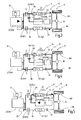
- Fig. 1 is a drive train for a motor vehicle 11 generally designated 10.
- the motor vehicle 11 may be, for example, a passenger car.
- the motor vehicle 11 is presently held on a slope which is oriented at an angle ⁇ to the horizontal, wherein ⁇ is not equal to 0 °.
- the drive train 10 includes a drive motor 12, for example in the form of an internal combustion engine, which is supplied from an energy store such as a fuel tank. Furthermore, the drive train 10 includes a friction clutch whose input member is connected to the engine 12 and whose output member is connected to the input of a transmission 32.
- the transmission 32 may be, for example, a countershaft transmission with multiple gear ratios, in particular five, six, seven, eight or more forward gear ratios and possibly a reverse gear.
- An output of the transmission 32 is connected to a schematically indicated differential 16 of a drive axle 17, the differential 16 serving to distribute drive power to driven wheels 18 of the drive axle 17.
- the powertrain 10 further includes an electric machine 40 and a controller 50.
- the clutch 30, the transmission 32 and the electric machine 40 are automatically operated by means of the control device 50. If the motor vehicle is to be approached from standstill on the slope, the user must release a brake pedal. In order to avoid that the motor vehicle rolls away in this case, a method for temporarily holding the motor vehicle on the slope is used. The detection of the release of the brake pedal and thus the detection of a holding request done in the control device. Unless already done, a hold gear is engaged in the transmission 32, for example, the lowest forward gear. Subsequently, the electric machine 40 is driven so that it provides a supportive holding torque for holding the motor vehicle on the slope.
- a supplemental holding torque may be provided, as long as the engine 12 is on or off, and the clutch 30 is preferably slipping in this case.
- Fig. 2 is another embodiment of a drive train for a motor vehicle 11 generally designated 10.
- the drive train 12 includes a drive motor, for example in the form of an internal combustion engine, which is supplied from an energy store such as a fuel tank 13.
- the drive train 10 includes a dual-clutch transmission (DCT) 14 whose output side is connected to a differential 16.
- DCT dual-clutch transmission
- the differential 16 distributes drive power to left and right driven wheels 18L, 18R of the drive axle 17.
- the dual-clutch transmission 14 includes a first friction clutch 30 and a first partial transmission 32.
- the first partial transmission 32 includes, for example, the odd gear ratios 1, 3, 5, etc., which are switched on and interpretable by means of associated clutches 34.
- the first friction clutch 30 and the first partial transmission 32 form a first power transmission path 36 for transmitting drive power from the drive motor 12 to the differential 16.
- the dual-clutch transmission 14 further includes a second friction clutch 20 and a second partial transmission 22.
- the second partial transmission 22 includes, for example, straight gear stages 2, 4, 6, which are switched on and interpretable by means of schematically indicated clutches 24.
- the second friction clutch 20 and the second partial transmission 22 form a second power transmission path 26 for transmitting power from the drive motor 12 to the differential 16.
- the drive train 10 includes the Fig. 2 an electrical machine 40 connected to a drive and power supply arrangement 42.
- the assembly 42 may include, for example, power electronics and a battery.
- the electric machine 40 is firmly connected to an input of the second partial transmission 22, for example by means of a spur gear or the like.
- the electric machine 40 by means of a dome assembly 44 (for example in the form of a clutch) to be connected to the input of the second sub-transmission 22 ,
- the electric machine 40 can also be connected alternatively to the input of the first partial transmission 32, for which purpose a suitable coupling device can be provided.
- connection of the electric machine 40 to that sub-transmission which has the highest gear and the reverse gear, allows an electric driving in almost all operating situations, as will be explained in addition.
- the powertrain is designed to operate in three different modes.
- drive power is only generated by the drive motor 12.
- Gear changes take place in an interruption-free manner by driving power being supplied via one of the power transmission paths 26, 36, a gear stage being preselected in the subtransmission of the other power transmission path. Subsequently, a gear change takes place by transferring the power transmission flow from one path to the other path by the friction clutches 20, 30 are operated in an overlapping manner.
- This drive mode is well known in the art of dual clutch transmissions.
- a second hybrid drive mode can be set up in the drive power of both the drive motor 12 and the electric machine 40 is provided.
- the drive powers can essentially be added via the summation point at the input of the second partial transmission 22 (or in the power flow direction behind the second friction clutch 20).
- Another possibility of a hybrid drive mode is that drive power is transmitted from the electric machine via the one partial transmission and drive power from the internal combustion engine via the other partial transmission, wherein a summing point then lies on the differential.
- a third drive mode is possible, in which only the electric machine 40 is driven to generate drive power, whereas the drive motor 12 is turned off or shut down. Since the electric machine 40 is connected to the secondary side of the second friction clutch 20, in this operating mode, the conventional shifting operations of a dual-clutch transmission can not be applied. However, in purely electric forward driving operation, gear changes can take place between the forward gears 2, 4, 6.
- an optionally provided starter / generator is provided which is usable for starting the internal combustion engine 12. In general, however, it is possible to start the internal combustion engine 12 by closing the first friction clutch 20 and by opening the clutches 24 by means of the electric machine 40.
- a first embodiment of such a method is based on Fig. 3 explained.
- the temporary holding function on the slope (“hillhold function") is made possible by the fact that with two engaged holding gear stages 1, 2 in the partial transmissions 22, 32 and slipping (S in Fig. 3 ) Operated clutches 20, 30, the torque of the internal combustion engine 12 is used to hold the vehicle 11.
- the heat development is split between the two clutches 20, 30.
- the electric machine 40 is decoupled mechanically or electrically and does not affect the output. Therefore, this method is also applicable to dual-clutch transmissions that have no electric machine 40.
- Fig. 4 is shown a further variant, which is also possible without electric machine.
- the hillhold function is made possible by the fact that with two engaged gear ratios 1, 2 in the partial transmissions 22, 32 and two closed (C in Fig. 4 ) Clutches 20, 30, the dual-clutch transmission 14 is braced and thus blocked, so that very high holding moments in the hillhold function are possible.
- the electric machine 40 in this case provides no holding torque, but can provide this as soon as a start is desired.
- the internal combustion engine is shut down or switched off in this variant.
- the hillhold function is made possible by the fact that in the second partial transmission 22, a holding gear stage is engaged, in particular a low gear, here the gear stage 2. Furthermore, the friction clutches 20, 30 are opened (O in Fig. 5 ).
- the internal combustion engine can be switched off, at least not acting on the output in the present case.
- the holding torque necessary for holding the motor vehicle on the slope is applied solely by the electric machine 40.
- a start can be done either via the electric machine. If this is already heavily loaded (for example, at high gradients), if necessary, the engine 12 can be started from the hillhold function out, and the motor vehicle can be approached via the first partial transmission 32. In this case, it is therefore advantageous if the separate starter / generator 46 is provided.
- the clutches 24 of the second sub-transmission 22 are opened.
- the clutches 20, 30 are each closed.
- a holding gear stage is engaged (here the gear 1).
- the engine 12 is turned off.
- the holding torque can be performed on the drive shaft 17 via a better transmission ratio, so that the electric machine 40 is loaded less.
- Added to the holding torque provided by the electric machine 40 is a holding torque of the internal combustion engine 12 which, in its disengaged state, additionally provides its breakaway torque.
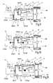
- Fig. 7 In another variant, the in Fig. 7 is shown, in turn, all the clutches 24 are opened in the second partial transmission 22.
- a Haltegang tone here gear 1
- a holding torque is provided both by the electric machine 40, for which purpose the second friction clutch 20 can be closed or is operated slipping.
- the first friction clutch 30 is also slipping actuated, and the engine 12 is turned on and also provides a holding torque. As a result, the torque provided by the electric machine 40 can be further reduced, so that its power electronics are loaded less (component protection).
- the in Fig. 8 is shown, the HillholdSch is made possible by the fact that in both partial transmissions 22, 32 each a holding gear stage is inserted. Furthermore, both friction clutches 20, 30 are slipping actuated. The electric machine can provide holding torque both via the second partial transmission 22 and possibly via the second friction clutch 20. The internal combustion engine provides holding torque via the slipping-actuated first friction clutch 30 and the first partial transmission 32. In this case, the second friction clutch 20 may also be opened so that the engine 12 provides holding torque via the power transmission path 36, and the electric machine 40 via the power transmission path 26.
- Such a variant is relatively easy to implement. Since the internal combustion engine 12 is already switched on, it is possible if necessary to approach it via the first friction clutch 30.
- the in Fig. 9 is shown, the HillholdSch is made possible by the fact that in both partial transmissions a Gargangnote is inserted.
- the second friction clutch 20 is opened (O).
- the first friction clutch 30 is closed.
- a holding torque is provided by the electric machine 40 via the second partial transmission 22.
- a supplemental holding torque is provided via the internal combustion engine 12 shut down in this case by providing a breakaway torque that is less than the torque required to start the internal combustion engine.
- the electrical machine can be relieved.
- the first friction clutch 30 may be closed, but may also be operated slipping. The latter case is preferred because this can be avoided that too much torque is transmitted from the drive axle to the engine 12, whereby its breakaway torque could be exceeded.
- FIG. 10 Another variant is in Fig. 10 shown, wherein a hillhold function is made possible by that in the first partial transmission 32, no gear is engaged and the first friction clutch 30 is opened.
- the holding gear stage 2 In the second partial transmission 22, the holding gear stage 2 is inserted, and the second friction clutch 20 is actuated slipping.
- the engine 12 is turned on.
- the holding torque is provided on the one hand by the electric machine 40, wherein a supplementary holding torque is provided by the internal combustion engine 12 via the slipping second friction clutch 20 at the input of the second partial transmission 22.
- Fig. 11 is shown a further variant of a hillhold function, in turn, in the first partial transmission 32, no gear is engaged and / or the first friction clutch 30 is open.
- the engine 12 is turned off.
- a supplementary holding torque is provided by the internal combustion engine 12 via the breakaway torque, wherein the second friction clutch 20 is also preferably slipping actuated in this case, wherein the supplementary holding torque of the internal combustion engine 12 is added to the holding torque of the electric machine 40 and on in the second sub-gear 22 inserted holding gear stage 2 is transmitted to the drive axle.
- the internal combustion engine 12 can be started when needed, and the motor vehicle 11 can approach via the first friction clutch 30 and the first partial transmission 32, for which it may be advantageous to pre-select the starting gear stage (1) in the first partial transmission 32.
- the holding function can be realized not only on a positive, rising slope, but also on a sloping slope. In this case, it may be necessary to rotate the moment provided by the electric machine 40 from the sign.
Landscapes
- Engineering & Computer Science (AREA)
- Chemical & Material Sciences (AREA)
- Combustion & Propulsion (AREA)
- Transportation (AREA)
- Mechanical Engineering (AREA)
- Automation & Control Theory (AREA)
- Physics & Mathematics (AREA)
- Mathematical Physics (AREA)
- Hybrid Electric Vehicles (AREA)
- Electric Propulsion And Braking For Vehicles (AREA)
- Arrangement Of Transmissions (AREA)
Applications Claiming Priority (1)
| Application Number | Priority Date | Filing Date | Title |
|---|---|---|---|
| DE102013000838.7A DE102013000838A1 (de) | 2013-01-21 | 2013-01-21 | Verfahren zum Halten eines Kraftfahrzeuges an einer Steigung |
Publications (3)
| Publication Number | Publication Date |
|---|---|
| EP2757005A2 true EP2757005A2 (fr) | 2014-07-23 |
| EP2757005A3 EP2757005A3 (fr) | 2016-03-09 |
| EP2757005B1 EP2757005B1 (fr) | 2020-03-04 |
Family
ID=49943211
Family Applications (1)
| Application Number | Title | Priority Date | Filing Date |
|---|---|---|---|
| EP14150960.4A Active EP2757005B1 (fr) | 2013-01-21 | 2014-01-13 | Procédé de retenue d'un véhicule automobile sur une pente |
Country Status (3)
| Country | Link |
|---|---|
| EP (1) | EP2757005B1 (fr) |
| CN (1) | CN103935355B (fr) |
| DE (1) | DE102013000838A1 (fr) |
Cited By (7)
| Publication number | Priority date | Publication date | Assignee | Title |
|---|---|---|---|---|
| CN105196989A (zh) * | 2015-08-25 | 2015-12-30 | 南车青岛四方机车车辆股份有限公司 | 一种动车组制动控制设备以及方法 |
| WO2018069213A1 (fr) * | 2016-10-13 | 2018-04-19 | GETRAG B.V. & Co. KG | Procédé permettant d'effectuer un mode de charge extra-lent et chaîne cinématique hybride associée |
| US10112613B2 (en) | 2016-02-12 | 2018-10-30 | Ford Global Technologies, Llc | Systems and methods for managing torque |
| CN111319608A (zh) * | 2019-12-27 | 2020-06-23 | 福建中维动力科技股份有限公司 | 基于一体式混合动力系统的倒车控制系统 |
| WO2020143979A1 (fr) * | 2019-01-10 | 2020-07-16 | Bayerische Motoren Werke Aktiengesellschaft | Unité de commande et procédé permettant de faire fonctionner un entraînement hybride pourvu d'une boîte de vitesse à double embrayage |
| CN111942171A (zh) * | 2019-05-14 | 2020-11-17 | 株式会社艾科赛迪 | 驱动单元 |
| WO2021233692A1 (fr) * | 2020-05-22 | 2021-11-25 | Magna Pt B.V. & Co. Kg | Groupe motopropulseur hybride avec fonction de changement de vitesse sans interruption de charge |
Families Citing this family (8)
| Publication number | Priority date | Publication date | Assignee | Title |
|---|---|---|---|---|
| JP2016141236A (ja) * | 2015-02-02 | 2016-08-08 | スズキ株式会社 | 駆動制御装置 |
| CN104742907B (zh) * | 2015-03-16 | 2017-12-15 | 郑州宇通客车股份有限公司 | 一种驻车控制方法和驻车控制系统 |
| DE102015220425A1 (de) * | 2015-10-20 | 2017-04-20 | Zf Friedrichshafen Ag | Verfahren zum Betrieb eines Kraftfahrzeugs, Steuerungseinrichtung sowie Kraftfahrzeug |
| US20190193736A1 (en) * | 2016-09-14 | 2019-06-27 | Jatco Ltd | Automatic transmission and control method of the same |
| DE102017104106A1 (de) | 2017-02-28 | 2018-08-30 | GETRAG B.V. & Co. KG | Verfahren zum Ansteuern eines Hybrid-Antriebsstranges |
| DE102017214396A1 (de) * | 2017-08-18 | 2019-02-21 | Bayerische Motoren Werke Aktiengesellschaft | Hybridantriebsgetriebeeinheit sowie Verfahren zum Betreiben eines Fahrzeugs mit Hybridantrieb |
| DE102018206130A1 (de) * | 2018-04-20 | 2019-10-24 | Magna Pt B.V. & Co. Kg | Verfahren zur Rückgewinnung von Energie des Verbrennungsmotors beim Hochschalten sowie Steuergerät zur Durchführung des Verfahrens |
| DE102021202437B4 (de) | 2021-03-12 | 2024-05-02 | Magna Pt B.V. & Co. Kg | Verfahren zur Auswahl eines Ablaufs zum Starten eines Verbrennungsmotors in einem Antriebsstrang mit elektrifiziertem Doppelkupplungsgetriebe |
Citations (2)
| Publication number | Priority date | Publication date | Assignee | Title |
|---|---|---|---|---|
| US6616572B2 (en) | 2000-11-28 | 2003-09-09 | Fuji Jukogyo Kabushiki Kaisha | Hill hold control apparatus for vehicle |
| US7166060B2 (en) | 2005-01-18 | 2007-01-23 | Ford Global Technologies, Llc. | Hill hold for a vehicle |
Family Cites Families (7)
| Publication number | Priority date | Publication date | Assignee | Title |
|---|---|---|---|---|
| DE102005049992B4 (de) * | 2005-10-12 | 2014-03-13 | Getrag Getriebe- Und Zahnradfabrik Hermann Hagenmeyer Gmbh & Cie Kg | Verfahren zum Steuern eines Antriebsstranges |
| DE112007001971A5 (de) * | 2006-09-15 | 2009-05-28 | Luk Lamellen Und Kupplungsbau Beteiligungs Kg | Verfahren zum Betreiben eines Hybridantriebsstrangs für ein Kraftfahrzeug |
| US7926889B2 (en) * | 2007-10-29 | 2011-04-19 | Textron Innovations Inc. | Hill hold for an electric vehicle |
| IT1395448B1 (it) * | 2009-09-03 | 2012-09-21 | Ferrari Spa | Metodo di avviamento di un motore termico di un veicolo con propulsione ibrida |
| US9457811B2 (en) * | 2009-09-17 | 2016-10-04 | Ford Global Technologies, Llc | Brake assisted vehicle engine restart on a road grade |
| DE102011003080A1 (de) * | 2011-01-19 | 2012-07-19 | Robert Bosch Gmbh | Verfahren und Vorrichtung zum Betreiben einer Antriebsvorrichtung |
| DE102011018203B4 (de) * | 2011-04-12 | 2017-07-27 | Getrag Getriebe- Und Zahnradfabrik Hermann Hagenmeyer Gmbh & Cie Kg | Verfahren zum Betreiben eines Hybrid-Antriebsstranges und Steuereinrichtung zum Betreiben eines Hybrid-Antriebsstranges |
-
2013
- 2013-01-21 DE DE102013000838.7A patent/DE102013000838A1/de not_active Withdrawn
-
2014
- 2014-01-13 EP EP14150960.4A patent/EP2757005B1/fr active Active
- 2014-01-21 CN CN201410028386.7A patent/CN103935355B/zh active Active
Patent Citations (2)
| Publication number | Priority date | Publication date | Assignee | Title |
|---|---|---|---|---|
| US6616572B2 (en) | 2000-11-28 | 2003-09-09 | Fuji Jukogyo Kabushiki Kaisha | Hill hold control apparatus for vehicle |
| US7166060B2 (en) | 2005-01-18 | 2007-01-23 | Ford Global Technologies, Llc. | Hill hold for a vehicle |
Cited By (14)
| Publication number | Priority date | Publication date | Assignee | Title |
|---|---|---|---|---|
| CN105196989A (zh) * | 2015-08-25 | 2015-12-30 | 南车青岛四方机车车辆股份有限公司 | 一种动车组制动控制设备以及方法 |
| CN105196989B (zh) * | 2015-08-25 | 2019-01-11 | 中车青岛四方机车车辆股份有限公司 | 一种动车组制动控制设备以及方法 |
| US10112613B2 (en) | 2016-02-12 | 2018-10-30 | Ford Global Technologies, Llc | Systems and methods for managing torque |
| WO2018069213A1 (fr) * | 2016-10-13 | 2018-04-19 | GETRAG B.V. & Co. KG | Procédé permettant d'effectuer un mode de charge extra-lent et chaîne cinématique hybride associée |
| CN109843685A (zh) * | 2016-10-13 | 2019-06-04 | 麦格纳Pt有限两合公司 | 用于执行蠕动充电运行的方法和用于其的混合动力传动系 |
| WO2020143979A1 (fr) * | 2019-01-10 | 2020-07-16 | Bayerische Motoren Werke Aktiengesellschaft | Unité de commande et procédé permettant de faire fonctionner un entraînement hybride pourvu d'une boîte de vitesse à double embrayage |
| CN113165503A (zh) * | 2019-01-10 | 2021-07-23 | 宝马股份公司 | 用于运行具有双离合器变速器的混合动力驱动装置的控制单元和方法 |
| US11642957B2 (en) | 2019-01-10 | 2023-05-09 | Bayerische Motoren Werke Aktiengesellschaft | Control unit and method for operating a hybrid drive with a dual clutch transmission |
| CN111942171A (zh) * | 2019-05-14 | 2020-11-17 | 株式会社艾科赛迪 | 驱动单元 |
| EP3738844A1 (fr) * | 2019-05-14 | 2020-11-18 | Exedy Corporation | Unité d'entraînement |
| CN111942171B (zh) * | 2019-05-14 | 2024-02-06 | 株式会社艾科赛迪 | 驱动单元 |
| CN111319608A (zh) * | 2019-12-27 | 2020-06-23 | 福建中维动力科技股份有限公司 | 基于一体式混合动力系统的倒车控制系统 |
| CN111319608B (zh) * | 2019-12-27 | 2023-09-26 | 福建中维动力科技股份有限公司 | 基于一体式混合动力系统的倒车控制系统 |
| WO2021233692A1 (fr) * | 2020-05-22 | 2021-11-25 | Magna Pt B.V. & Co. Kg | Groupe motopropulseur hybride avec fonction de changement de vitesse sans interruption de charge |
Also Published As
| Publication number | Publication date |
|---|---|
| EP2757005A3 (fr) | 2016-03-09 |
| CN103935355A (zh) | 2014-07-23 |
| EP2757005B1 (fr) | 2020-03-04 |
| CN103935355B (zh) | 2017-01-04 |
| DE102013000838A1 (de) | 2014-07-24 |
Similar Documents
| Publication | Publication Date | Title |
|---|---|---|
| EP2757005B1 (fr) | Procédé de retenue d'un véhicule automobile sur une pente | |
| EP2765338B1 (fr) | Procédé destiné au fonctionnement d'une chaîne cinématique hybridée de boîte de vitesses à double embrayage | |
| EP2708400B1 (fr) | Procédé destiné à la commande d'une chaîne d'entraînement hybride | |
| EP2307251B1 (fr) | Procédé et dispositif pour démarrer un véhicule hybride | |
| DE102010044618B4 (de) | Verfahren zum Ansteuern eines Hybrid-Antriebsstranges | |
| EP2855226B1 (fr) | Procédé et dispositif de commande d'une machine de travail mobile | |
| DE102011018203B4 (de) | Verfahren zum Betreiben eines Hybrid-Antriebsstranges und Steuereinrichtung zum Betreiben eines Hybrid-Antriebsstranges | |
| DE102007055827A1 (de) | Verfahren und Vorrichtung zum Betrieb eines Hybridantriebes eines Fahrzeuges | |
| DE112018004616B4 (de) | Verfahren zur Steuerung eines Fahrzeugs mit einem Doppelkupplungsgetriebe, sowie Steuergerät zur Ausführung dieses Verfahrens und Fahrzeug mit einem solchen Steuergerät | |
| DE102016214148A1 (de) | Verfahren zum Ausstieg aus einer Rekuperationsphase in einem Parallelhybridfahrzeug | |
| DE102010023093A1 (de) | Antriebsstrang für ein Kraftfahrzeug und Verfahren zum Ansteuern eines Kraftfahrzeug-Antriebsstranges | |
| DE102017117079A1 (de) | Kraftfahrzeug-Immobilisierungsverfahren und Doppelkupplungsgetriebe | |
| DE102017216984A1 (de) | Verfahren zur Ansteuerung eines Stufengetriebes und eines Antriebsstranges, sowie Steuereinrichtung und Antriebsstrang | |
| DE102019220191A1 (de) | Verfahren zum Starten eines Verbrennungsmotors in einem Antriebsstrang mit hybridisiertem Doppelkupplungsgetriebe | |
| EP2699826B1 (fr) | Procédé permettant de faire fonctionner un véhicule automobile en poussée | |
| DE102010022912B4 (de) | Verfahren zum Ansteuern eines Kraftfahrzeug-Antriebsstranges | |
| WO2019025401A1 (fr) | Boîte de vitesses pour un système de propulsion hybride, système de propulsion hybride, véhicule, procédé pour faire fonctionner ledit système de propulsion hybride, programme informatique et support d'enregistrement | |
| DE102012222112A1 (de) | Antriebsstrang mit einem Doppelkupplungsgetriebe und Verfahren zu dessen Steuerung | |
| EP3589509B1 (fr) | Procédé de commande d'une chaîne cinématique hybride | |
| EP3771583B1 (fr) | Procédé de démarrage d'un moteur à combustion interne dans une chaine cinématique pourvue de boîte de vitesses hybride à double embrayage | |
| DE102019215082B3 (de) | Verfahren zum Zurückschalten im elektrischen Betrieb sowie Steuergerät zur Durchführung des Verfahrens | |
| EP3797231B1 (fr) | Chaîne cinématique d'un véhicule automobile et procédé pour faire fonctionner une chaîne cinématique | |
| DE102017214121A1 (de) | Verfahren zum Ansteuern eines Antriebsstranges für ein Kraftfahrzeug sowie Steuereinrichtung | |
| EP3526094B1 (fr) | Procédé permettant d'effectuer un mode de charge extra-lent et chaîne cinématique hybride associée | |
| DE102017213329A1 (de) | Getriebe für eine Hybridantriebsanordnung |
Legal Events
| Date | Code | Title | Description |
|---|---|---|---|
| PUAI | Public reference made under article 153(3) epc to a published international application that has entered the european phase |
Free format text: ORIGINAL CODE: 0009012 |
|
| 17P | Request for examination filed |
Effective date: 20140113 |
|
| AK | Designated contracting states |
Kind code of ref document: A2 Designated state(s): AL AT BE BG CH CY CZ DE DK EE ES FI FR GB GR HR HU IE IS IT LI LT LU LV MC MK MT NL NO PL PT RO RS SE SI SK SM TR |
|
| AX | Request for extension of the european patent |
Extension state: BA ME |
|
| PUAL | Search report despatched |
Free format text: ORIGINAL CODE: 0009013 |
|
| AK | Designated contracting states |
Kind code of ref document: A3 Designated state(s): AL AT BE BG CH CY CZ DE DK EE ES FI FR GB GR HR HU IE IS IT LI LT LU LV MC MK MT NL NO PL PT RO RS SE SI SK SM TR |
|
| AX | Request for extension of the european patent |
Extension state: BA ME |
|
| RIC1 | Information provided on ipc code assigned before grant |
Ipc: B60T 7/12 20060101AFI20160203BHEP Ipc: B60W 30/18 20120101ALI20160203BHEP |
|
| R17P | Request for examination filed (corrected) |
Effective date: 20160428 |
|
| RBV | Designated contracting states (corrected) |
Designated state(s): AL AT BE BG CH CY CZ DE DK EE ES FI FR GB GR HR HU IE IS IT LI LT LU LV MC MK MT NL NO PL PT RO RS SE SI SK SM TR |
|
| RAP1 | Party data changed (applicant data changed or rights of an application transferred) |
Owner name: GETRAG B.V. & CO. KG |
|
| RAP1 | Party data changed (applicant data changed or rights of an application transferred) |
Owner name: MAGNA PT B.V. & CO. KG |
|
| GRAP | Despatch of communication of intention to grant a patent |
Free format text: ORIGINAL CODE: EPIDOSNIGR1 |
|
| STAA | Information on the status of an ep patent application or granted ep patent |
Free format text: STATUS: GRANT OF PATENT IS INTENDED |
|
| INTG | Intention to grant announced |
Effective date: 20190826 |
|
| GRAS | Grant fee paid |
Free format text: ORIGINAL CODE: EPIDOSNIGR3 |
|
| GRAA | (expected) grant |
Free format text: ORIGINAL CODE: 0009210 |
|
| STAA | Information on the status of an ep patent application or granted ep patent |
Free format text: STATUS: THE PATENT HAS BEEN GRANTED |
|
| AK | Designated contracting states |
Kind code of ref document: B1 Designated state(s): AL AT BE BG CH CY CZ DE DK EE ES FI FR GB GR HR HU IE IS IT LI LT LU LV MC MK MT NL NO PL PT RO RS SE SI SK SM TR |
|
| REG | Reference to a national code |
Ref country code: GB Ref legal event code: FG4D Free format text: NOT ENGLISH |
|
| REG | Reference to a national code |
Ref country code: CH Ref legal event code: EP |
|
| REG | Reference to a national code |
Ref country code: AT Ref legal event code: REF Ref document number: 1240021 Country of ref document: AT Kind code of ref document: T Effective date: 20200315 |
|
| REG | Reference to a national code |
Ref country code: DE Ref legal event code: R096 Ref document number: 502014013724 Country of ref document: DE |
|
| REG | Reference to a national code |
Ref country code: IE Ref legal event code: FG4D Free format text: LANGUAGE OF EP DOCUMENT: GERMAN |
|
| PG25 | Lapsed in a contracting state [announced via postgrant information from national office to epo] |
Ref country code: FI Free format text: LAPSE BECAUSE OF FAILURE TO SUBMIT A TRANSLATION OF THE DESCRIPTION OR TO PAY THE FEE WITHIN THE PRESCRIBED TIME-LIMIT Effective date: 20200304 Ref country code: NO Free format text: LAPSE BECAUSE OF FAILURE TO SUBMIT A TRANSLATION OF THE DESCRIPTION OR TO PAY THE FEE WITHIN THE PRESCRIBED TIME-LIMIT Effective date: 20200604 Ref country code: RS Free format text: LAPSE BECAUSE OF FAILURE TO SUBMIT A TRANSLATION OF THE DESCRIPTION OR TO PAY THE FEE WITHIN THE PRESCRIBED TIME-LIMIT Effective date: 20200304 |
|
| REG | Reference to a national code |
Ref country code: NL Ref legal event code: MP Effective date: 20200304 |
|
| PG25 | Lapsed in a contracting state [announced via postgrant information from national office to epo] |
Ref country code: BG Free format text: LAPSE BECAUSE OF FAILURE TO SUBMIT A TRANSLATION OF THE DESCRIPTION OR TO PAY THE FEE WITHIN THE PRESCRIBED TIME-LIMIT Effective date: 20200604 Ref country code: GR Free format text: LAPSE BECAUSE OF FAILURE TO SUBMIT A TRANSLATION OF THE DESCRIPTION OR TO PAY THE FEE WITHIN THE PRESCRIBED TIME-LIMIT Effective date: 20200605 Ref country code: SE Free format text: LAPSE BECAUSE OF FAILURE TO SUBMIT A TRANSLATION OF THE DESCRIPTION OR TO PAY THE FEE WITHIN THE PRESCRIBED TIME-LIMIT Effective date: 20200304 Ref country code: LV Free format text: LAPSE BECAUSE OF FAILURE TO SUBMIT A TRANSLATION OF THE DESCRIPTION OR TO PAY THE FEE WITHIN THE PRESCRIBED TIME-LIMIT Effective date: 20200304 Ref country code: HR Free format text: LAPSE BECAUSE OF FAILURE TO SUBMIT A TRANSLATION OF THE DESCRIPTION OR TO PAY THE FEE WITHIN THE PRESCRIBED TIME-LIMIT Effective date: 20200304 |
|
| REG | Reference to a national code |
Ref country code: LT Ref legal event code: MG4D |
|
| PG25 | Lapsed in a contracting state [announced via postgrant information from national office to epo] |
Ref country code: NL Free format text: LAPSE BECAUSE OF FAILURE TO SUBMIT A TRANSLATION OF THE DESCRIPTION OR TO PAY THE FEE WITHIN THE PRESCRIBED TIME-LIMIT Effective date: 20200304 |
|
| PG25 | Lapsed in a contracting state [announced via postgrant information from national office to epo] |
Ref country code: SK Free format text: LAPSE BECAUSE OF FAILURE TO SUBMIT A TRANSLATION OF THE DESCRIPTION OR TO PAY THE FEE WITHIN THE PRESCRIBED TIME-LIMIT Effective date: 20200304 Ref country code: PT Free format text: LAPSE BECAUSE OF FAILURE TO SUBMIT A TRANSLATION OF THE DESCRIPTION OR TO PAY THE FEE WITHIN THE PRESCRIBED TIME-LIMIT Effective date: 20200729 Ref country code: EE Free format text: LAPSE BECAUSE OF FAILURE TO SUBMIT A TRANSLATION OF THE DESCRIPTION OR TO PAY THE FEE WITHIN THE PRESCRIBED TIME-LIMIT Effective date: 20200304 Ref country code: SM Free format text: LAPSE BECAUSE OF FAILURE TO SUBMIT A TRANSLATION OF THE DESCRIPTION OR TO PAY THE FEE WITHIN THE PRESCRIBED TIME-LIMIT Effective date: 20200304 Ref country code: CZ Free format text: LAPSE BECAUSE OF FAILURE TO SUBMIT A TRANSLATION OF THE DESCRIPTION OR TO PAY THE FEE WITHIN THE PRESCRIBED TIME-LIMIT Effective date: 20200304 Ref country code: RO Free format text: LAPSE BECAUSE OF FAILURE TO SUBMIT A TRANSLATION OF THE DESCRIPTION OR TO PAY THE FEE WITHIN THE PRESCRIBED TIME-LIMIT Effective date: 20200304 Ref country code: LT Free format text: LAPSE BECAUSE OF FAILURE TO SUBMIT A TRANSLATION OF THE DESCRIPTION OR TO PAY THE FEE WITHIN THE PRESCRIBED TIME-LIMIT Effective date: 20200304 Ref country code: ES Free format text: LAPSE BECAUSE OF FAILURE TO SUBMIT A TRANSLATION OF THE DESCRIPTION OR TO PAY THE FEE WITHIN THE PRESCRIBED TIME-LIMIT Effective date: 20200304 Ref country code: IS Free format text: LAPSE BECAUSE OF FAILURE TO SUBMIT A TRANSLATION OF THE DESCRIPTION OR TO PAY THE FEE WITHIN THE PRESCRIBED TIME-LIMIT Effective date: 20200704 |
|
| REG | Reference to a national code |
Ref country code: DE Ref legal event code: R097 Ref document number: 502014013724 Country of ref document: DE |
|
| PLBE | No opposition filed within time limit |
Free format text: ORIGINAL CODE: 0009261 |
|
| STAA | Information on the status of an ep patent application or granted ep patent |
Free format text: STATUS: NO OPPOSITION FILED WITHIN TIME LIMIT |
|
| PG25 | Lapsed in a contracting state [announced via postgrant information from national office to epo] |
Ref country code: IT Free format text: LAPSE BECAUSE OF FAILURE TO SUBMIT A TRANSLATION OF THE DESCRIPTION OR TO PAY THE FEE WITHIN THE PRESCRIBED TIME-LIMIT Effective date: 20200304 Ref country code: DK Free format text: LAPSE BECAUSE OF FAILURE TO SUBMIT A TRANSLATION OF THE DESCRIPTION OR TO PAY THE FEE WITHIN THE PRESCRIBED TIME-LIMIT Effective date: 20200304 |
|
| 26N | No opposition filed |
Effective date: 20201207 |
|
| PG25 | Lapsed in a contracting state [announced via postgrant information from national office to epo] |
Ref country code: PL Free format text: LAPSE BECAUSE OF FAILURE TO SUBMIT A TRANSLATION OF THE DESCRIPTION OR TO PAY THE FEE WITHIN THE PRESCRIBED TIME-LIMIT Effective date: 20200304 Ref country code: SI Free format text: LAPSE BECAUSE OF FAILURE TO SUBMIT A TRANSLATION OF THE DESCRIPTION OR TO PAY THE FEE WITHIN THE PRESCRIBED TIME-LIMIT Effective date: 20200304 |
|
| PG25 | Lapsed in a contracting state [announced via postgrant information from national office to epo] |
Ref country code: MC Free format text: LAPSE BECAUSE OF FAILURE TO SUBMIT A TRANSLATION OF THE DESCRIPTION OR TO PAY THE FEE WITHIN THE PRESCRIBED TIME-LIMIT Effective date: 20200304 |
|
| REG | Reference to a national code |
Ref country code: CH Ref legal event code: PL |
|
| PG25 | Lapsed in a contracting state [announced via postgrant information from national office to epo] |
Ref country code: LU Free format text: LAPSE BECAUSE OF NON-PAYMENT OF DUE FEES Effective date: 20210113 |
|
| REG | Reference to a national code |
Ref country code: BE Ref legal event code: MM Effective date: 20210131 |
|
| PG25 | Lapsed in a contracting state [announced via postgrant information from national office to epo] |
Ref country code: CH Free format text: LAPSE BECAUSE OF NON-PAYMENT OF DUE FEES Effective date: 20210131 Ref country code: LI Free format text: LAPSE BECAUSE OF NON-PAYMENT OF DUE FEES Effective date: 20210131 |
|
| PG25 | Lapsed in a contracting state [announced via postgrant information from national office to epo] |
Ref country code: IE Free format text: LAPSE BECAUSE OF NON-PAYMENT OF DUE FEES Effective date: 20210113 |
|
| REG | Reference to a national code |
Ref country code: AT Ref legal event code: MM01 Ref document number: 1240021 Country of ref document: AT Kind code of ref document: T Effective date: 20210113 |
|
| PG25 | Lapsed in a contracting state [announced via postgrant information from national office to epo] |
Ref country code: AT Free format text: LAPSE BECAUSE OF NON-PAYMENT OF DUE FEES Effective date: 20210113 |
|
| PG25 | Lapsed in a contracting state [announced via postgrant information from national office to epo] |
Ref country code: BE Free format text: LAPSE BECAUSE OF NON-PAYMENT OF DUE FEES Effective date: 20210131 |
|
| PG25 | Lapsed in a contracting state [announced via postgrant information from national office to epo] |
Ref country code: HU Free format text: LAPSE BECAUSE OF FAILURE TO SUBMIT A TRANSLATION OF THE DESCRIPTION OR TO PAY THE FEE WITHIN THE PRESCRIBED TIME-LIMIT; INVALID AB INITIO Effective date: 20140113 |
|
| PG25 | Lapsed in a contracting state [announced via postgrant information from national office to epo] |
Ref country code: CY Free format text: LAPSE BECAUSE OF FAILURE TO SUBMIT A TRANSLATION OF THE DESCRIPTION OR TO PAY THE FEE WITHIN THE PRESCRIBED TIME-LIMIT Effective date: 20200304 |
|
| PG25 | Lapsed in a contracting state [announced via postgrant information from national office to epo] |
Ref country code: MK Free format text: LAPSE BECAUSE OF FAILURE TO SUBMIT A TRANSLATION OF THE DESCRIPTION OR TO PAY THE FEE WITHIN THE PRESCRIBED TIME-LIMIT Effective date: 20200304 |
|
| PG25 | Lapsed in a contracting state [announced via postgrant information from national office to epo] |
Ref country code: MT Free format text: LAPSE BECAUSE OF FAILURE TO SUBMIT A TRANSLATION OF THE DESCRIPTION OR TO PAY THE FEE WITHIN THE PRESCRIBED TIME-LIMIT Effective date: 20200304 |
|
| REG | Reference to a national code |
Ref country code: DE Ref legal event code: R082 Ref document number: 502014013724 Country of ref document: DE Representative=s name: EULER, MATTHIAS, DR., DE |
|
| REG | Reference to a national code |
Ref country code: DE Ref legal event code: R081 Ref document number: 502014013724 Country of ref document: DE Owner name: MAGNA PT B.V. & CO. KGAA, DE Free format text: FORMER OWNER: MAGNA PT B.V. & CO. KG, 74199 UNTERGRUPPENBACH, DE |
|
| PG25 | Lapsed in a contracting state [announced via postgrant information from national office to epo] |
Ref country code: TR Free format text: LAPSE BECAUSE OF FAILURE TO SUBMIT A TRANSLATION OF THE DESCRIPTION OR TO PAY THE FEE WITHIN THE PRESCRIBED TIME-LIMIT Effective date: 20200304 |
|
| PGFP | Annual fee paid to national office [announced via postgrant information from national office to epo] |
Ref country code: GB Payment date: 20260123 Year of fee payment: 13 |
|
| PGFP | Annual fee paid to national office [announced via postgrant information from national office to epo] |
Ref country code: DE Payment date: 20260121 Year of fee payment: 13 |
|
| PGFP | Annual fee paid to national office [announced via postgrant information from national office to epo] |
Ref country code: FR Payment date: 20260123 Year of fee payment: 13 |