EP2757384A2 - Procédé et dispositif de détection de fautes dans une machine électrique - Google Patents
Procédé et dispositif de détection de fautes dans une machine électrique Download PDFInfo
- Publication number
- EP2757384A2 EP2757384A2 EP13198077.3A EP13198077A EP2757384A2 EP 2757384 A2 EP2757384 A2 EP 2757384A2 EP 13198077 A EP13198077 A EP 13198077A EP 2757384 A2 EP2757384 A2 EP 2757384A2
- Authority
- EP
- European Patent Office
- Prior art keywords
- machine
- model
- stator
- rotor
- parameters
- Prior art date
- Legal status (The legal status is an assumption and is not a legal conclusion. Google has not performed a legal analysis and makes no representation as to the accuracy of the status listed.)
- Withdrawn
Links
- 238000000034 method Methods 0.000 title claims abstract description 68
- 238000005457 optimization Methods 0.000 claims abstract description 34
- 230000008569 process Effects 0.000 claims abstract description 23
- 238000003745 diagnosis Methods 0.000 claims abstract description 10
- 238000010586 diagram Methods 0.000 claims description 19
- 241000555745 Sciuridae Species 0.000 claims description 5
- 238000013178 mathematical model Methods 0.000 claims description 3
- 230000036962 time dependent Effects 0.000 claims description 2
- 230000007547 defect Effects 0.000 abstract 1
- XEEYBQQBJWHFJM-UHFFFAOYSA-N Iron Chemical compound [Fe] XEEYBQQBJWHFJM-UHFFFAOYSA-N 0.000 description 11
- 238000004804 winding Methods 0.000 description 10
- 238000004364 calculation method Methods 0.000 description 7
- 230000006698 induction Effects 0.000 description 7
- 230000007257 malfunction Effects 0.000 description 7
- 230000009466 transformation Effects 0.000 description 7
- 238000004422 calculation algorithm Methods 0.000 description 6
- 239000004020 conductor Substances 0.000 description 6
- 230000008878 coupling Effects 0.000 description 6
- 238000010168 coupling process Methods 0.000 description 6
- 238000005859 coupling reaction Methods 0.000 description 6
- 230000008859 change Effects 0.000 description 5
- 230000004907 flux Effects 0.000 description 5
- 229910052742 iron Inorganic materials 0.000 description 5
- 238000005259 measurement Methods 0.000 description 5
- 238000012544 monitoring process Methods 0.000 description 5
- RYGMFSIKBFXOCR-UHFFFAOYSA-N Copper Chemical compound [Cu] RYGMFSIKBFXOCR-UHFFFAOYSA-N 0.000 description 4
- 229910052802 copper Inorganic materials 0.000 description 4
- 239000010949 copper Substances 0.000 description 4
- 230000001419 dependent effect Effects 0.000 description 4
- 230000000694 effects Effects 0.000 description 4
- 239000007787 solid Substances 0.000 description 4
- 230000032683 aging Effects 0.000 description 3
- 238000001514 detection method Methods 0.000 description 3
- 238000009413 insulation Methods 0.000 description 3
- 238000004519 manufacturing process Methods 0.000 description 3
- 230000010363 phase shift Effects 0.000 description 3
- 238000002945 steepest descent method Methods 0.000 description 3
- 241001136792 Alle Species 0.000 description 2
- 230000002500 effect on skin Effects 0.000 description 2
- 239000000543 intermediate Substances 0.000 description 2
- 230000036961 partial effect Effects 0.000 description 2
- 238000005070 sampling Methods 0.000 description 2
- 241000965481 Darksidea alpha Species 0.000 description 1
- 238000004458 analytical method Methods 0.000 description 1
- 230000021615 conjugation Effects 0.000 description 1
- 238000010924 continuous production Methods 0.000 description 1
- 230000003247 decreasing effect Effects 0.000 description 1
- 238000009795 derivation Methods 0.000 description 1
- 238000013461 design Methods 0.000 description 1
- 230000005674 electromagnetic induction Effects 0.000 description 1
- 230000002068 genetic effect Effects 0.000 description 1
- 238000007689 inspection Methods 0.000 description 1
- 230000005415 magnetization Effects 0.000 description 1
- 238000012423 maintenance Methods 0.000 description 1
- 239000000463 material Substances 0.000 description 1
- 230000009467 reduction Effects 0.000 description 1
- 230000005417 remagnetization Effects 0.000 description 1
- 239000000126 substance Substances 0.000 description 1
- 230000002123 temporal effect Effects 0.000 description 1
- 230000001131 transforming effect Effects 0.000 description 1
Images


Classifications
-
- G—PHYSICS
- G01—MEASURING; TESTING
- G01R—MEASURING ELECTRIC VARIABLES; MEASURING MAGNETIC VARIABLES
- G01R31/00—Arrangements for testing electric properties; Arrangements for locating electric faults; Arrangements for electrical testing characterised by what is being tested not provided for elsewhere
- G01R31/34—Testing dynamo-electric machines
- G01R31/343—Testing dynamo-electric machines in operation
Definitions
- the invention relates to a method for detecting errors of an electrical machine, which are associated with input variables, output variables and machine parameters. It further relates to an apparatus for carrying out such a method.
- the simplest type of engine control is to monitor the measurable quantities of the electrical system and, in the event of a malfunction, either cut off the power supply or take other safety measures in the event that a measured value exceeds a permissible limit. This can at least prevent the malfunction of the engine from damaging its environment.
- the disadvantage here is that the associated demolition of the production process can cause high costs and losses if it takes place at an unfavorable time.
- production processes in the chemical industry often require a continuous process.
- a process interruption can lead to non-recyclable intermediates and thus to rejects.
- unscheduled interruptions can lead to high profit losses and thus high economic losses.
- the invention has for its object to provide a method for detecting errors, in which the errors can be detected during operation. Furthermore, an apparatus for carrying out this method should be specified.
- the invention is based on the consideration that to avoid the above-mentioned technical and economic disadvantages malfunctions and malfunctions in the operation should be identified before they lead to a failure of the machine and further to disturbances of the environment and thus the process. This requires the detection of even small deviations from normal case.
- these quantities can be determined indirectly by simulating them during operation of the engine, the outputs of the simulated machine being functions of their model parameters or electrical quantities. This corresponds to the case of the physical machine, in which the measurable output variables also depend on the electrical parameters or machine parameters.
- Inferring the parameters of the machine can be achieved by varying the model parameters until the outputs of the simulated machine are sufficiently matched to those of the physical machine. This variation of the model parameters can be targeted by an optimization process. On the basis of the then determined values of the model parameters, a diagnosis of the machine state can be carried out by assigning the changed value of the parameter to a possible probable damage scenario.
- the unit function is selected for at least one model function. That is, the respective model parameter corresponds directly to the corresponding machine parameter. As a result, it is possible to deduce the value of a model parameter directly from the machine parameter, so that the assignment to a specific damage scenario is simplified.
- the unit function is selected for each model function, the model parameters correspond directly to the machine parameters.
- effective model parameters may be used that are functions of one or more model parameters. This can be advantageous in parameter optimization. For example, if two parameters are about the same size in size, but cause conflicting effects, it may be useful to use them to form the sum and the difference and to determine these two new effective parameters in the optimization process.
- the input variables preferably comprise one or more elements of the group: three-phase sinusoidal AC voltage, single-phase AC voltage, DC current.
- the model has input variables whose values can be set to the input variables of the electrical machine during the initial adjustment.
- the outputs preferably comprise one or more elements of the group: stator current, stator voltage, rotor speed, electrical torque, mechanical torque. These variables are also measurable during operation of the asynchronous machine in a simple and precise manner and are therefore suitable for monitoring the machine and for detecting a deviating from the normal case running behavior of the machine.
- the model is time-dependent and comprises an electrical equivalent circuit diagram of the asynchronous motor.
- the output variables are then measured with a predetermined sampling interval and the resulting time-discrete functions are solved numerically.
- An equivalent circuit diagram allows a simplified representation of the electrical variables and their functional relationships and thus reduces the computational effort. Mathematical-physical simplifications of the model are unproblematic, as long as conclusions about the machine parameters are still reliably possible.
- a single-phase equivalent circuit diagram can be used, which can then be extended to three phases by recording the symmetry conditions of the phases relative to each other and the spatial structure (in each case 120 ° between the phases).
- a gradient step method is used for the optimization.
- the conjugate gradient step method is used for this purpose. This differs from the standard gradient step method essentially in the calculation of the gradient, in which earlier minimization or maximization directions in the parameter space are taken into account. The two methods thus differ in the calculation of the search direction, ie. H. the direction in the multidimensional parameter space, in which one or more parameters are changed in the next step.
- the conjugation factor can be calculated by the Polak-Ribiere formula.
- the Armijo Rule can be used to determine an efficient step size.
- a principal problem of the steepest descent methods mentioned above is that their search result is highly dependent on the initial conditions.
- each newly found parameter combination corresponds to a lower value of the minimization function.
- the nearest local minimum is found.
- this does not necessarily correspond to the global minimum, which corresponds to the globally optimal solution of the parameters.
- Algorithms with a statistical component that greatly increase the likelihood of finding the global minimum are Evolutionary Algorithms or even Genetic Algorithms and Swarm Strategies. However, these algorithms may require too much time, so they can only be used in specific cases when there is enough time for your work.
- the above object is achieved according to the invention with means for carrying out the method described above.
- the method may be implemented on a computer by a program implementing the model and at least one optimization algorithm.
- a measuring device must be provided with the aid of which the output variables of the electrical machine can be measured regularly and at predetermined time sampling intervals.
- an interface should be provided by which these quantities are transmitted to the computer.
- the measured and the calculated output variables as well as the model parameters can then be output on an output unit, in particular a monitor.
- a database in which deviations of the model parameters from normal values are respectively assigned to one or more damage scenarios.
- damage can be identified early and countermeasures can be taken to prevent even greater damage.
- the machine may be stopped and a component that exhibits severe wear or material damage may be replaced.
- an output unit may be provided, on which the probable damage and possibly also proposals for measures to be taken are displayed, for example, also for the planning of inspection and maintenance of the engine.
- the advantages of the invention are, in particular, that no elaborate measuring devices have to be installed to determine cases of damage during the ongoing operation of a machine, but rather the measurements of the output variables are sufficient for the diagnosis of the machine. Even small errors with effects on the electrical parameters of the machine can be detected early. It can be seen in this way in asynchronous machines changes in internal electrical variables and thus errors such as rod breakage, insulation damage and errors due to the natural aging process.
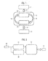
- An in FIG. 1 shown flow diagram of the method according to the invention in one preferred embodiment comprises a first block 2, in which carried out an initial adjustment between the input variables of an induction motor with a squirrel cage and a model.
- the values for resistors and inductances specified by the manufacturer's documentation are entered into the model. It is assumed that the machine is in perfect condition. However, these variables have deviations from the desired model parameters, on the one hand due to design conditions (the values are not determined on each individual machine, but given for a dedicated model series), on the other hand they are skin effects, caused by the magnetic coupling of the individual strands, and the resulting losses, not taken into account.
- the parameters are adapted to multiply inductances by a factor of 0.6 to account for the reactive power required for magnetic coupling, and resistors by a factor of 0.85 to determine the temperature difference between the maximum temperature specified by the manufacturer and the Time of adjustment to balance current ambient temperature (normal room temperature). With the model thus set, the first adjustment is carried out, so that the parameters can be determined in error-free condition.
- the model includes an equivalent circuit diagram for the asynchronous motor.
- the input variables are all three stator voltages U s1 , U s2 and U s3 as complex quantities with magnitude and phase. This initialization causes the temporal evolution of the model to start with the same initial conditions that apply to the physical machine.
- the difference or deviation of the respectively simulated variable from the measured variable is determined and checked whether this difference exceeds a predetermined limit value or threshold value. If this deviation for only one quantity and / or the sum or another function of the deviations does not fulfill a predefined criteria with regard to one or more limit values, a further measurement is again carried out in block 22.
- the method steps are performed in block 30.
- the sum of the quadratic deviations that forms the optimization function is minimized in a conjugate gradient step method. Since the optimization function is a function of the model parameters, the result of the optimization procedure is a new set of model parameters. Only one or more of the model parameters may have changed.
- the model parameters correspond to the machine parameters in the present exemplary embodiment. These include stator and rotor resistors and stator and rotor inductors.
- FIG. 2 is an alternative diagram illustrating the method according to FIG. 1 shown.
- the input variables are determined which represent the initial conditions both for the physical process in block 44, ie for the operation of the asynchronous motor, and for the mathematical model in block 48.
- the measured outputs are compared with the outputs predicted by the model. In the present case, this comparison always takes place when a new measurement of the physical output variables has taken place and corresponds to the processes in block 10 according to FIG FIG. 1 , If a deviation exceeds a threshold At block 56, a minimization of the optimization function is performed, resulting in new model parameters (this corresponds to block 30) FIG. 1 ).
- FIG. 3 A single-phase equivalent circuit 68 of an asynchronous motor with a squirrel-cage rotor is shown in FIG FIG. 3 shown.
- This equivalent circuit diagram depicts a stator of the total of three stators of the asynchronous motor.
- three of these equivalent circuit diagrams can be combined. This procedure is sufficient in the present case, since, apart from phase shifts, the physical processes in the individual stator strands are the same. This also applies to the physical processes in the rotor branches.
- the magnetic flux and the electric current are in phase in each stator string, so that, in effect, the magnetic flux seems to be generated by only one phase, though it is generated by all the phases.
- the stator phase is assigned a supply voltage U s , which is provided by a voltage supply 70.
- the copper and iron losses of the stator, which are connected in series, are described by the stator resistance R s , that of the rotor by the rotor resistance R r .
- Stray fields resulting from the electromagnetic induction are described by stray inductances, for the stator by the stator inductance L s , and for the rotor by the rotor inductance L r .
- Each rotor phase is assigned a resulting rotor voltage U r .
- an induced stator voltage U qs is generated in the stator and an induced rotor voltage U qr is generated in the rotor.
- the voltage drop on the rotor side depends on the supply voltage U s on the stator side and the number of turns between the stator and rotor circuits.
- f N The frequency of the supply voltage in the stator windings
- f N The frequency of the supply network of 50 Hz.
- the frequency of all physical processes on the rotor side results from the difference between the rotational speed of the rotor and the rotational speed of the magnetic field of the stator. This frequency is always lower than the frequency of the stator by the factor s, which denotes the electrical slip.
- f is the frequency of the rotor current and rotor voltage in the unit Hertz r (Hz)
- n M is the rotational speed of the rotor in the unit min -1 .
- Z r is the complex impedance, consisting of resistance and reactance in [ ⁇ ]
- U r the voltage drop at the impedance (amplitude and phase) in [V]
- I r is the current through the impedance (amplitude and phase) in [A]
- Z ' r transforms the complex impedance, to the primary side of the system, into [ ⁇ ].
- the magnetic coupling between the stator and rotor circuits can be described as a parallel reactance L h between these two circuits.
- the equivalent circuit obtained in this way includes only coils and resistors.
- a resistor R fe is connected in parallel with the main inductance L h .
- stator windings When extending the equivalent circuit diagram to three phases, the sources of the magnetic field - the stator windings and the rotor windings - must each be considered separately. While the stator strands have a fixed spatial arrangement, each with 120 ° angle between the individual branches, the rotor rotates at a certain rotational speed, which implies that the stator strands experience time-varying magnetic fields.
- self-induction describes the property of a conductor to create a magnetic field that counteracts current changes. This leads to voltage drops on the corresponding conductors.
- u q is the induced voltage in [V]
- L is the inductance that generates the magnetic field in [H]
- i is the time varying current flowing through inductor L in [A].
- the magnetic flux affecting the adjacent strands is by definition only generated by the main inductance L h and the resulting voltage is the self-induced Opposite voltage.
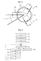
- the magnetic flux of a phase that affects the neighboring phases can then be determined using the cosine of the solid angle or intermediate angle between the phases, see Fig. 4 , in which three stator strands s1, s2, s3 are shown, between each of which an angle of 60 ° is located.
- L h1 is the main inductance of the stator strand 1
- L s1 the stray inductance of the stator strand 1
- i s1 the current flowing in stator strand 1 current.
- u Ls2 and u Ls3 are the voltages induced by stator strand 2 or 3
- L h1 and L h2 are the main inductances of stator cords 2 and 3
- i s1 and i s2 are the alternating current flowing in stator strand 1 and 2
- u Lr1 , u Lr2 and u Lr3 are the rotor-induced voltages in [V]
- L h1 , L h2 and L h3 are the main inductances in the three rotor strands in [H]
- i r1 , i r2 and i r3 are the alternating currents in the three rotor strands in [A] and ⁇ of the effective angle of the rotor within the stator windings which varies with ⁇ M over time
- L s L H ⁇ 1 + L s ⁇ 1 - 1 2 ⁇ L H ⁇ 2 - 1 2 L H ⁇ 3
- L r L H ⁇ 1 ⁇ cos ⁇ L H ⁇ 2 ⁇ cos ⁇ + 2 ⁇ ⁇ 3
- i s i s ⁇ 1 i s ⁇ 2 i s ⁇ 3
- i r i r ⁇ 1 i r ⁇ 2 i r ⁇ 3 T
- u r ⁇ 1 u rr ⁇ 1 + u Lr ⁇ 1 + u Lr ⁇ 2 + u Lr ⁇ 3 + u ls ⁇ 1 + u ls ⁇ 2 + u ls ⁇ 3
- u r ⁇ 1 R r ⁇ 1 ⁇ i r ⁇ 1 + L r ⁇ di r dt + L s ⁇ di s dt
- L r L H ⁇ 1 + L r ⁇ 1 - 1 2 ⁇ L H ⁇ 2 - 1 2 L H ⁇ 3
- L s L H ⁇ 1 ⁇ cos ⁇ L H ⁇ 2 ⁇ cos ⁇ - 2 ⁇ ⁇ 3
- i r i r ⁇ 1 i r ⁇ 2 i r ⁇ 3
- i s i s ⁇ 1 i s ⁇ 2 i s ⁇ 3 T
- i s i s ⁇ 1 i s ⁇ 2 i s ⁇ 3 .
- R s R s ⁇ 1 0 0 0 R s ⁇ 2 0 0 0 R s ⁇ 3 .
- L r L H ⁇ 1 + L r ⁇ 1 - L H ⁇ 2 2 - L H ⁇ 3 2 - L H ⁇ 1 2 L H ⁇ 2 + L r ⁇ 2 - L H ⁇ 3 2 - L H ⁇ 1 2 - L H ⁇ 2 2 L H ⁇ 3 + L r ⁇ 3
- the equation system now consists of 6 differential equations and can be increased by two more with the help of the torque equations.
- M el 1 2 ⁇ i s i r T ⁇ d d ⁇ ⁇ L s L sr ⁇ L rs ⁇ L r ⁇ i s i r
- the model In order to be able to monitor an asynchronous machine with the help of the model, the model must first be parameterized such that the output variables of the model (stator current and rotational speed of the rotor) correspond to those of the variables measurable on the real machine. Since the system of equations with 15 parameters is underdetermined in 8 differential equations, the initial parameters must be chosen as closely as possible to the actual parameters. For this purpose, the values of the single-phase equivalent circuit diagram supplied by the manufacturer of the machine are used, whereby the main inductances must be reduced by 1/3 in order to take into account the three-phase structure.
- FIG. 6 A flowchart of an optimization process that is part of the process is in FIG. 6 shown.
- the initial values of all model parameters are selected. These values represent the output values for the parameters of the system of differential equations.
- the quantity g (c) is then calculated, which represents the quadratic standard deviation between a measured and a calculated series of output variables.
- the gradient ⁇ g ( c ) of size g (c) is then calculated. The result of this operation is a 15-dimensional vector in the space of the machine parameters, which is perpendicular to the equipotential surfaces and points in that space in the direction of the largest change.
- the norm of the gradient is calculated, which makes it possible to formulate a suitable termination parameter optimization parameter.
- the optimization is aborted if the norm of the gradient falls below a predetermined threshold value (in this case, the deviation between measured variables and model parameter is sufficiently small).
- a predetermined threshold value in this case, the deviation between measured variables and model parameter is sufficiently small.
- the smaller the norm of the gradient the smaller the largest slope, ie, in the multidimensional Parameter space becomes smaller and smaller with decreasing gradient the descent (in the case of minimization), which usually indicates that the optimum value or at least a local optimum has already been achieved relatively well.
- block 116 it is checked whether the gradient standard is greater than a predefined threshold value. If this is not the case, the minimization in block 120 is ended. Otherwise, the minimization is started in block 124 or in the form of a loop which comprises blocks 124, 128, 132, 136 and 116.
- the gradients are used to calculate the new values of the model parameters (the steepest descent method). The step size in the direction of the individual gradient directions is determined using the Armijo-Goldstein rule, which ensures that a reduction of g (c) is achieved.
- the new parameters are stored in block 128.
- the gradient is again calculated, and in block 136 its norm is calculated.
- the method then proceeds to block 116, where the abort criterion is rechecked. If satisfied, the optimization process ends in block 120.
- the result of the optimization is then a new set of machine parameters with which the solution of the differential equation system provides an improved approximation to the measured outputs.
- the result of the optimization is strongly dependent on the initial values of the parameters.
- the initial values of the model can be found in the manufacturer's documentation and the machine has to be continuously monitored in order to detect changes in the parameters early on and to be able to adapt the model accordingly.
- An exemplary motor in which a fault diagnosis can be carried out with the described method has the following characteristics: Nominal voltage: 400 V, 50 Hz Current Rating: 4.5 A Rated torque: 7.4 Nm Rated capacity: 2.2 kW Maximum torque: 16 Nm
- the input quantities of the motor are the rated voltage and frequency.
- the outputs that are measured and used to perform the optimization are stator current and rotor speed.
- FIG. 3 shows a device 150 for carrying out a method as described above in a preferred embodiment.
- the apparatus 150 comprises an initial matching module 154, in which the initial comparison between the input variables of the machine and the corresponding input variables of the model is carried out.
- a monitoring module 158 the machine is monitored at predetermined times or even contingently on the basis of the output variables, wherein it is checked whether these are from a normal case, the one error-free operation of the machine, deviate.
- optimization of the model parameters is carried out in an optimization module 162 in such a way that the output variables of the machine are matched with those of the model in the best possible way, which can be achieved, for example, by minimizing the sum of their quadratic deviations ( X 2 -fit).
- a fault diagnosis is now carried out on the basis of the new set of model parameters determined by the optimization module 162.
- the modules 154, 158, 162 and 166 are interconnected via a data link 170 and can communicate with each other. They can be implemented as software modules on a common hardware architecture or as separate hardware modules that communicate with each other, for example via a common bus.
- the device 150 further comprises a database 174, which is connected to the diagnostic module 166 via a data connection 178.
- a database 174 a plurality of damage scenarios are stored, each associated with deviations of the model parameters from their normal values corresponding to an intact machine.
- the diagnostic module 174 can therefore query the database whether a present damage scenario is already known, whereby the diagnosis of the machine and a corresponding message can be carried out very effectively and quickly possible.
Landscapes
- Physics & Mathematics (AREA)
- General Physics & Mathematics (AREA)
- Control Of Electric Motors In General (AREA)
- Control Of Ac Motors In General (AREA)
- Testing And Monitoring For Control Systems (AREA)
Applications Claiming Priority (1)
| Application Number | Priority Date | Filing Date | Title |
|---|---|---|---|
| DE102013200872.4A DE102013200872A1 (de) | 2013-01-21 | 2013-01-21 | Verfahren und Vorrichtung zur Erkennung von Fehlern einer elektrischen Maschine |
Publications (2)
| Publication Number | Publication Date |
|---|---|
| EP2757384A2 true EP2757384A2 (fr) | 2014-07-23 |
| EP2757384A3 EP2757384A3 (fr) | 2017-07-19 |
Family
ID=49767013
Family Applications (1)
| Application Number | Title | Priority Date | Filing Date |
|---|---|---|---|
| EP13198077.3A Withdrawn EP2757384A3 (fr) | 2013-01-21 | 2013-12-18 | Procédé et dispositif de détection de fautes dans une machine électrique |
Country Status (2)
| Country | Link |
|---|---|
| EP (1) | EP2757384A3 (fr) |
| DE (1) | DE102013200872A1 (fr) |
Cited By (4)
| Publication number | Priority date | Publication date | Assignee | Title |
|---|---|---|---|---|
| CN111913107A (zh) * | 2020-08-18 | 2020-11-10 | 湖南湘电动力有限公司 | 一种绕线式异步发电机的试验方法 |
| CN112329342A (zh) * | 2020-11-02 | 2021-02-05 | 北京信息科技大学 | 湿式离合器摩擦元件损伤加权阈值预测方法及存储介质 |
| CN113009333A (zh) * | 2019-12-19 | 2021-06-22 | 珠海万谱科技有限公司 | 一种感应电机转子气隙偏心检测方法及装置 |
| CN118688632A (zh) * | 2024-08-29 | 2024-09-24 | 常州博安和达机电科技有限公司 | 一种基于数据分析的推杆电机性能检测系统及方法 |
Families Citing this family (3)
| Publication number | Priority date | Publication date | Assignee | Title |
|---|---|---|---|---|
| DE102015013016B4 (de) | 2015-10-07 | 2017-04-27 | Audi Ag | Verfahren zum Klassifizieren eines Zustands einer Elektromaschine |
| DE102019201985B4 (de) * | 2019-02-14 | 2024-03-07 | Vitesco Technologies GmbH | Verfahren zum Erkennen eines Fehlers einer elektrischen Maschine für ein Fahrzeug |
| AT527242A1 (de) * | 2023-05-23 | 2024-12-15 | Avl List Gmbh | Verfahren und Kontrollvorrichtung zur Ermittlung von optimiert-identifzierten Maschinenparametern eines Elektromotors |
Family Cites Families (6)
| Publication number | Priority date | Publication date | Assignee | Title |
|---|---|---|---|---|
| US6014598A (en) * | 1996-06-28 | 2000-01-11 | Arcelik A.S. | Model-based fault detection system for electric motors |
| GB2378248A (en) * | 2001-05-09 | 2003-02-05 | Worcester Entpr Ltd | A fault prediction system for vehicles |
| WO2008006655A1 (fr) * | 2006-07-13 | 2008-01-17 | Alstom Technology Ltd | Procédé et dispositif pour la détection de courts-circuits interlaminaires |
| US8866626B2 (en) * | 2008-01-31 | 2014-10-21 | Basler Electric Company | System and method for detecting generator incipient failures |
| DE102008028264B3 (de) * | 2008-06-13 | 2009-12-17 | Knorr-Bremse Systeme für Schienenfahrzeuge GmbH | Verfahren zur Überwachung wenigstens eines das Betriebsverhalten von Fahrzeugen oder Fahrzeugzügen beeinflussenden Systemparameters |
| DE102008030544B4 (de) * | 2008-06-27 | 2014-05-22 | Siemens Aktiengesellschaft | Modellbasiertes Verfahren zur Überwachung von mikromechanischen Pumpen |
-
2013
- 2013-01-21 DE DE102013200872.4A patent/DE102013200872A1/de not_active Withdrawn
- 2013-12-18 EP EP13198077.3A patent/EP2757384A3/fr not_active Withdrawn
Non-Patent Citations (1)
| Title |
|---|
| None |
Cited By (7)
| Publication number | Priority date | Publication date | Assignee | Title |
|---|---|---|---|---|
| CN113009333A (zh) * | 2019-12-19 | 2021-06-22 | 珠海万谱科技有限公司 | 一种感应电机转子气隙偏心检测方法及装置 |
| CN113009333B (zh) * | 2019-12-19 | 2024-02-09 | 珠海万谱科技有限公司 | 一种感应电机转子气隙偏心检测方法及装置 |
| CN111913107A (zh) * | 2020-08-18 | 2020-11-10 | 湖南湘电动力有限公司 | 一种绕线式异步发电机的试验方法 |
| CN111913107B (zh) * | 2020-08-18 | 2023-05-23 | 湖南湘电动力有限公司 | 一种绕线式异步发电机的试验方法 |
| CN112329342A (zh) * | 2020-11-02 | 2021-02-05 | 北京信息科技大学 | 湿式离合器摩擦元件损伤加权阈值预测方法及存储介质 |
| CN112329342B (zh) * | 2020-11-02 | 2023-05-23 | 北京信息科技大学 | 湿式离合器摩擦元件损伤加权阈值预测方法及存储介质 |
| CN118688632A (zh) * | 2024-08-29 | 2024-09-24 | 常州博安和达机电科技有限公司 | 一种基于数据分析的推杆电机性能检测系统及方法 |
Also Published As
| Publication number | Publication date |
|---|---|
| EP2757384A3 (fr) | 2017-07-19 |
| DE102013200872A1 (de) | 2014-07-24 |
Similar Documents
| Publication | Publication Date | Title |
|---|---|---|
| EP2757384A2 (fr) | Procédé et dispositif de détection de fautes dans une machine électrique | |
| EP2279549B1 (fr) | Procédé de détection d'une erreur dans une machine à induction | |
| EP2421148A1 (fr) | Dispositif et procédé d'identification des paramètres de référence mécaniques d'un moteur asynchrone triphasé sans utilisation d'encodeur de vitesse | |
| DE102013110106A1 (de) | Online-Überwachung der Statorisolierung in Motoren und Generatoren | |
| DE102012105850A1 (de) | Fahrzeug-gestütztes System und Isolationsfehler-Diagnoseeinheit | |
| EP2421145A1 (fr) | Dispositif et procédé d'identification des paramètres d'un schéma électrique équivalent d'un moteur asynchrone triphasé sans utilisation d'encodeur de vitesse | |
| DE112018001976T5 (de) | Stückweise schätzung von gegenspannung zur fehlererkennung in elektrischen systemen | |
| EP3100064B2 (fr) | Dispositif et procédé de détection de défauts dans des machines | |
| EP2538547B1 (fr) | Dispositif et procédé d'identification de paramètres mécaniques d'un moteur linéaire asynchrone sans capteur de position | |
| DE102013012861A1 (de) | Diagnoseverfahren für eine elektrische Maschine | |
| DE102010053098A1 (de) | Verfahren zur Überwachung eines Rotorlagegebers | |
| EP2903153B1 (fr) | Analyse des vibrations et des bruits d'une machine électrique alimentée par un convertisseur | |
| EP3151072B1 (fr) | Procede et systeme de reconnaissance de defaut et de surveillance pour un composant de machine commande ou regle electroniquement | |
| DE112013003953T5 (de) | Automatisierte Motoranpassung | |
| DE102023101527A1 (de) | Verfahren zur Zustandsüberwachung einer technischen Einrichtung | |
| DE102016222546A1 (de) | Verfahren und Vorrichtung zum Entkoppeln der Phasen eines Elektromotors und Antriebssystem mit einem sechsphasigen Elektromotor | |
| EP1943714B1 (fr) | Procédé de surveillance automatique du fonctionnement d' un générateur | |
| DE102011089341A1 (de) | Bestimmen eines Winkels zwischen einem Stator und einem Rotor einer fremderregten Synchronmaschine | |
| DE102015110460A1 (de) | Erkennung eines Netzphasenausfalls bei Umrichtern mit einer Frequenzdetektion in der Zwischenkreisspannung | |
| DE102015223211A1 (de) | Verfahren zum Erkennen eines Fehlers in einer Generatoreinheit | |
| DE102019005013A1 (de) | Motorsteuerung und motorsteuerverfahren | |
| DE102018103831A1 (de) | Verfahren und Vorrichtung zur adaptiven rotororientierten Regelung und Drehmomentschätzung einer permanentmagneterregten Synchronmaschine auf Basis von Schätzungen des magnetischen Flusses im stationären Zustand | |
| DE102018002188A1 (de) | Verfahren zum Prüfen eines Antriebs und Antrieb | |
| DE102024114211B4 (de) | Verfahren und Kontrollvorrichtung zur Ermittlung von optimiert-identifzierten Maschinenparametern eines Elektromotors | |
| EP3560097B1 (fr) | Procédé pour faire fonctionner un système d'entraînement et système d'entraînement |
Legal Events
| Date | Code | Title | Description |
|---|---|---|---|
| PUAI | Public reference made under article 153(3) epc to a published international application that has entered the european phase |
Free format text: ORIGINAL CODE: 0009012 |
|
| 17P | Request for examination filed |
Effective date: 20131218 |
|
| AK | Designated contracting states |
Kind code of ref document: A2 Designated state(s): AL AT BE BG CH CY CZ DE DK EE ES FI FR GB GR HR HU IE IS IT LI LT LU LV MC MK MT NL NO PL PT RO RS SE SI SK SM TR |
|
| AX | Request for extension of the european patent |
Extension state: BA ME |
|
| PUAL | Search report despatched |
Free format text: ORIGINAL CODE: 0009013 |
|
| AK | Designated contracting states |
Kind code of ref document: A3 Designated state(s): AL AT BE BG CH CY CZ DE DK EE ES FI FR GB GR HR HU IE IS IT LI LT LU LV MC MK MT NL NO PL PT RO RS SE SI SK SM TR |
|
| AX | Request for extension of the european patent |
Extension state: BA ME |
|
| RIC1 | Information provided on ipc code assigned before grant |
Ipc: G01R 31/34 20060101AFI20170612BHEP |
|
| STAA | Information on the status of an ep patent application or granted ep patent |
Free format text: STATUS: THE APPLICATION IS DEEMED TO BE WITHDRAWN |
|
| 18D | Application deemed to be withdrawn |
Effective date: 20180120 |