EP2757545A2 - Hinweistafel, insbesondere für eine Notbeleuchtungsanlage - Google Patents
Hinweistafel, insbesondere für eine Notbeleuchtungsanlage Download PDFInfo
- Publication number
- EP2757545A2 EP2757545A2 EP14152214.4A EP14152214A EP2757545A2 EP 2757545 A2 EP2757545 A2 EP 2757545A2 EP 14152214 A EP14152214 A EP 14152214A EP 2757545 A2 EP2757545 A2 EP 2757545A2
- Authority
- EP
- European Patent Office
- Prior art keywords
- web
- recess
- light
- reflector
- display
- Prior art date
- Legal status (The legal status is an assumption and is not a legal conclusion. Google has not performed a legal analysis and makes no representation as to the accuracy of the status listed.)
- Granted
Links
Images



Classifications
-
- G—PHYSICS
- G09—EDUCATION; CRYPTOGRAPHY; DISPLAY; ADVERTISING; SEALS
- G09F—DISPLAYING; ADVERTISING; SIGNS; LABELS OR NAME-PLATES; SEALS
- G09F13/00—Illuminated signs; Luminous advertising
- G09F13/18—Edge-illuminated signs
-
- G—PHYSICS
- G02—OPTICS
- G02B—OPTICAL ELEMENTS, SYSTEMS OR APPARATUS
- G02B6/00—Light guides; Structural details of arrangements comprising light guides and other optical elements, e.g. couplings
-
- G—PHYSICS
- G02—OPTICS
- G02B—OPTICAL ELEMENTS, SYSTEMS OR APPARATUS
- G02B6/00—Light guides; Structural details of arrangements comprising light guides and other optical elements, e.g. couplings
- G02B6/0001—Light guides; Structural details of arrangements comprising light guides and other optical elements, e.g. couplings specially adapted for lighting devices or systems
- G02B6/0011—Light guides; Structural details of arrangements comprising light guides and other optical elements, e.g. couplings specially adapted for lighting devices or systems the light guides being planar or of plate-like form
- G02B6/0013—Means for improving the coupling-in of light from the light source into the light guide
- G02B6/0015—Means for improving the coupling-in of light from the light source into the light guide provided on the surface of the light guide or in the bulk of it
- G02B6/002—Means for improving the coupling-in of light from the light source into the light guide provided on the surface of the light guide or in the bulk of it by shaping at least a portion of the light guide, e.g. with collimating, focussing or diverging surfaces
- G02B6/0021—Means for improving the coupling-in of light from the light source into the light guide provided on the surface of the light guide or in the bulk of it by shaping at least a portion of the light guide, e.g. with collimating, focussing or diverging surfaces for housing at least a part of the light source, e.g. by forming holes or recesses
-
- G—PHYSICS
- G02—OPTICS
- G02B—OPTICAL ELEMENTS, SYSTEMS OR APPARATUS
- G02B6/00—Light guides; Structural details of arrangements comprising light guides and other optical elements, e.g. couplings
- G02B6/0001—Light guides; Structural details of arrangements comprising light guides and other optical elements, e.g. couplings specially adapted for lighting devices or systems
- G02B6/0011—Light guides; Structural details of arrangements comprising light guides and other optical elements, e.g. couplings specially adapted for lighting devices or systems the light guides being planar or of plate-like form
- G02B6/0013—Means for improving the coupling-in of light from the light source into the light guide
- G02B6/0023—Means for improving the coupling-in of light from the light source into the light guide provided by one optical element, or plurality thereof, placed between the light guide and the light source, or around the light source
- G02B6/0031—Reflecting element, sheet or layer
-
- G—PHYSICS
- G02—OPTICS
- G02B—OPTICAL ELEMENTS, SYSTEMS OR APPARATUS
- G02B6/00—Light guides; Structural details of arrangements comprising light guides and other optical elements, e.g. couplings
- G02B6/0001—Light guides; Structural details of arrangements comprising light guides and other optical elements, e.g. couplings specially adapted for lighting devices or systems
- G02B6/0011—Light guides; Structural details of arrangements comprising light guides and other optical elements, e.g. couplings specially adapted for lighting devices or systems the light guides being planar or of plate-like form
- G02B6/0066—Light guides; Structural details of arrangements comprising light guides and other optical elements, e.g. couplings specially adapted for lighting devices or systems the light guides being planar or of plate-like form characterised by the light source being coupled to the light guide
- G02B6/0068—Arrangements of plural sources, e.g. multi-colour light sources
-
- G—PHYSICS
- G02—OPTICS
- G02B—OPTICAL ELEMENTS, SYSTEMS OR APPARATUS
- G02B6/00—Light guides; Structural details of arrangements comprising light guides and other optical elements, e.g. couplings
- G02B6/0001—Light guides; Structural details of arrangements comprising light guides and other optical elements, e.g. couplings specially adapted for lighting devices or systems
- G02B6/0011—Light guides; Structural details of arrangements comprising light guides and other optical elements, e.g. couplings specially adapted for lighting devices or systems the light guides being planar or of plate-like form
- G02B6/0066—Light guides; Structural details of arrangements comprising light guides and other optical elements, e.g. couplings specially adapted for lighting devices or systems the light guides being planar or of plate-like form characterised by the light source being coupled to the light guide
- G02B6/0073—Light emitting diode [LED]
-
- G—PHYSICS
- G02—OPTICS
- G02B—OPTICAL ELEMENTS, SYSTEMS OR APPARATUS
- G02B6/00—Light guides; Structural details of arrangements comprising light guides and other optical elements, e.g. couplings
- G02B6/0001—Light guides; Structural details of arrangements comprising light guides and other optical elements, e.g. couplings specially adapted for lighting devices or systems
- G02B6/0011—Light guides; Structural details of arrangements comprising light guides and other optical elements, e.g. couplings specially adapted for lighting devices or systems the light guides being planar or of plate-like form
- G02B6/0081—Mechanical or electrical aspects of the light guide and light source in the lighting device peculiar to the adaptation to planar light guides, e.g. concerning packaging
- G02B6/0085—Means for removing heat created by the light source from the package
-
- G—PHYSICS
- G08—SIGNALLING
- G08B—SIGNALLING SYSTEMS, e.g. PERSONAL CALLING SYSTEMS; ORDER TELEGRAPHS; ALARM SYSTEMS
- G08B7/00—Signalling systems according to two or more of groups G08B3/00 - G08B6/00
- G08B7/06—Signalling systems according to two or more of groups G08B3/00 - G08B6/00 using electric transmission, e.g. involving audible and visible signalling through the use of sound and light sources
- G08B7/062—Signalling systems according to two or more of groups G08B3/00 - G08B6/00 using electric transmission, e.g. involving audible and visible signalling through the use of sound and light sources indicating emergency exits
-
- G—PHYSICS
- G09—EDUCATION; CRYPTOGRAPHY; DISPLAY; ADVERTISING; SEALS
- G09F—DISPLAYING; ADVERTISING; SIGNS; LABELS OR NAME-PLATES; SEALS
- G09F13/00—Illuminated signs; Luminous advertising
- G09F13/04—Signs, boards or panels, illuminated from behind the insignia
- G09F13/0418—Constructional details
- G09F2013/05—Constructional details indicating exit way or orientation
-
- G—PHYSICS
- G09—EDUCATION; CRYPTOGRAPHY; DISPLAY; ADVERTISING; SEALS
- G09F—DISPLAYING; ADVERTISING; SIGNS; LABELS OR NAME-PLATES; SEALS
- G09F13/00—Illuminated signs; Luminous advertising
- G09F13/20—Illuminated signs; Luminous advertising with luminescent surfaces or parts
- G09F13/22—Illuminated signs; Luminous advertising with luminescent surfaces or parts electroluminescent
- G09F2013/222—Illuminated signs; Luminous advertising with luminescent surfaces or parts electroluminescent with LEDs
Definitions
- the invention relates to a signboard, in particular for an emergency lighting system, with a backlit display, with at least one light-emitting diode and provided for backlighting the display photoconductive plate which forms a recess separated by a web of one of its broad sides recess, wherein the recess at least one light-emitting diode receives, which is optically connected via an adjoining the web recess surface with the photoconductive plate, wherein the web at least partially backlit the display.
- a photoconductive plate DE9417471 U1
- DE9417471 U1 For backlighting of a display is known from the prior art, a photoconductive plate ( DE9417471 U1 ), which has in a narrow side a central recess with inserted LED bulbs to illuminate a provided on their broadsides display.
- the forming between the recess and the broad sides of the plate webs are illuminated by the diodes used, however, relatively uneven.
- This disadvantage is additionally reinforced by the comparatively narrow emission characteristic of the diodes. Homogeneous illumination up to the edges of the broadside can therefore not guarantee such devices, so that they can only be used to a limited extent despite their compact design - in particular if they are to be used for illumination as frameless information signs or security lighting with pictograms.
- photoconductive plates for constructing a backlight of LCD displays are known. So that beats EP2423718A2 to provide the LED provided for illuminating the photoconductive plate in a recess of the plate so as to protect it.
- the invention is therefore based on the task to improve a billboard of the type described in a structurally simple manner such that, despite a compact, frameless design for a sufficient and uniform brightness over the entire surface of the broadside is taken care of - especially up to all Edge.
- the invention achieves the stated object in that the cross section of the web, in particular over the course of the recess facing web flank, at least partially increases in the direction of the recess surface for improved backlighting of the display.
- the cross section of the web increases at least in regions in the direction of the recess surface, a particularly wide entrance surface for light reflected from the plate into the web and thus improved backlighting of the display can be created - in particular in the region of the web.
- the web formed by the photoconductive plate can thus be supplied in a structurally simple manner with a sufficient amount of light, even in the material-reduced plate area no discernible differences in brightness must be feared.
- the display can therefore be illuminated particularly well even in the region of the web of the plate.
- the light incident thereon can be sufficiently guided or directed to the edge formed by the broad and narrow side.
- the web-side backlighting of the display can thus be improved.
- a frameless billboard which has particularly advantageous illumination conditions according to the invention.
- the use of a light-emitting diode as a light source can be made possible, although they have a comparatively narrow radiation characteristic. Namely, it can be ensured by the shape of the light-conducting web that the light reflected back from the plate is caught even better in the case of a web which is comparatively narrow in its cross-section and safely directed in order to secure the plate to lighten evenly.
- the indirect optical connection of the diode to the web can therefore provide a sufficiently backlit display. In other words, since the diode light essentially couples into the ridge via an indirect optical path, it is also possible to avoid undesired, focused illumination known from diodes.
- the construction conditions can be simplified if the cross-section of the web over the course of the recess facing web edge in the direction of the recess surface increases at least partially.
- the design measures for web illumination can be provided in the recess and thus removed from the field of view of the billboard.
- a billboard with a particular advantage backlit display available that is frameless and / or small in size and thus low in their production costs.
- the information panel according to the invention may be, for example, emergency lighting for an emergency lighting system (not shown).
- this billboard may have one or more pictograms that are backlit.
- the broad side of a plate can be considered to be its front and / or back, which are spaced apart by narrow sides.
- the construction conditions of a billboard can be simplified if the web is at least partially wedge-shaped in cross-section. Through this design of the web all the above advantages are achieved. In addition, the reflection effect of the wedge surface can be used to homogenize the light distribution in the web.
- the diode is connected to the web only optically indirectly, in order to avoid, for example by direct diode illumination known disadvantageous focusing effects.
- the backlight of the display can thus be further improved.
- the signboard has a reflector which adjoins the web at least in some areas, this can contribute to uniformly bright illumination of the entire broad side of the plate.
- a reflector can be used to guide the light emitted by diodes improved, which can also be achieved that light incident in its intensity uniformly in a photoconductive plate. With the help of a reflector, it is also possible to stably prevent light from directly entering the web from light-emitting diodes, which can undesirably illuminate the bridge.
- the diodes used by the reflector optically in the background - or to some extent not be visible. Therefore, a bridge provided with a reflector can not only provide for particularly advantageous lighting conditions on the display, but also facilitate a compact and frameless design of the billboard.
- the reflector carries at least one diode.
- the reflector may be formed metallic and connected in heat conduction with at least one diode in order to cool the diode so.
- the life of the diode can be increased, especially as can be ensured by means of the reflector acting as a heat sink for a uniform temperature distribution when multiple diodes are used to backlight the display.
- the billboard has a board protruding from the reflector, on which at least one diode is mounted and which forms a stop for positioning the diode in the recess, structurally simple conditions for producing the billboard can be created. Furthermore, the maintenance of a light source or of diodes can be simplified by this stop.
- a particularly advantageous illumination of a billboard can be achieved if the reflector forms a diaphragm for limiting the direct light irradiation of at least one diode in the web. For this purpose, it may be provided that the reflector covers the entire recess-side web surface. According to the invention, this advantage, in conjunction with the already mentioned advantage of the reflection of light in the web, can lead to a particularly well and homogeneously illuminated information panel.
- the reflector can be integrally formed and U-shaped and form a recessed with respect to its two legs receptacle for at least one diode.
- the legs can act as glare and / or visual protection for the reflector or diode arranged concealed in the reflector.
- Thermal expansion effects can be easily compensated by the reflector is arranged spaced from the recess surface.
- the reflector in the direction of the bottom of the recess is a possibility for thermal expansion available, which can increase the stability of the billboard.
- the design conditions for the backlighting of displays on both broad sides of a light-conducting plate can be simplified by the recess is separated by a respective web from the respective broad side and the reflector connects at least partially to both webs.
- the recess may also be provided in one of the broad sides of the photoconductive plate while achieving the aforementioned advantages in order to couple light from the diode into the photoconductive plate.
- An outcoupling of light beyond the web can be prevented in a structurally simple manner if the narrow end of the web has a light-reflecting layer.
- the light emission of the plate can be selectively changed and adjusted in order to further compensate for any brightness differences. A particularly uniform backlighting of the display of the billboard according to the invention can thus be ensured.
- the bridge for supporting the display can be made comparatively slim, since the mechanical loads on a web can be reduced.
- Such a protection of the photoconductive plate can be used according to the invention to form a slim billboard and subsequently lead to a compact design of the billboard. This compact design can also be achieved if at least one broad side of the photoconductive plate is flush with the display.
- FIG. 1 For example, according to a first embodiment illustrated billboard 1 is part of a security lighting, not shown, and carries as a display 2, for example, a green icon with an arrow.
- the display 2 is illuminated in the background, for which light emitting diodes 3 (LEDs) are provided.
- the diodes 3 may also be provided with a housing not shown in detail and / or with a lens, not shown. All diodes 3 are mounted on a circuit board 4 and electrically connected via this board 4.
- the diodes 3 are used to illuminate a photoconductive plate 5, in particular for backlighting the display 2 on the broad side 8 of the plate 5.
- the plate 5 on its upper narrow side 6 has a recess 7.
- the diodes 3 are used.
- the recess 7 is provided centrally in the plate 5 at its upper narrow side 6, so that the recess 7 is separated on both sides by a respective web 9 of the broad sides 8 of the plate 5.
- the plate 5 now in the areas of the webs 9 reduced thicknesses, which hampers a homogeneous bright illumination of the broad side 8 and provided in the region of the web 9 display 2.
- the cross section of the web 9 increases in the direction of the recess surface 14 at least partially.
- the diodes 3 are optically connected via the recess surface 14 with the photoconductive plate 5, as described in detail of Fig. 3 can be removed.
- the display 2 is illuminated in this area substantially with indirect diode light by initially collected directly via the recess surface 14 in the plate 5 coupled diode light by reflection in the land to the backlight.
- An unwanted direct coupling of diode light in the web 9 can therefore be omitted, which a uniform backlight of the display 2 is conducive.
- the entire width side 8 of the plate 5 without hesitation - due to uniform and even all over - illumination with the thus illuminated in the background display 2 are provided.
- the web shape is formed by the cross section of the web 9 over the course of the recess 7 facing web edge 10 in the direction of the recess surface 14 steadily increases. This measure can keep the broad side 8 free of relevant design features and thus guarantee, for example, flatness.
- a reflector 11 is for example a mirror, a reflective film or vapor-deposited on the web 9 mirror layer conceivable.
- a metallic body can be used, which can also contribute to the cooling in thermal bond with the diodes 3.
- the webs 9 in cross-section on a wedge shape and extends the recess surface 14 through which the diodes 3 are optically connected to the photoconductive plate 5, perpendicular to the broad side. 8
- the main axis 13 of the radiation of the diodes 3 runs parallel to the broad side 8 of the plate 5.
- the reflector 11 forms a diaphragm.
- the reflector 11 projects significantly deeper into the recess 7, as is the case with the diodes 3. Any focal points of the diodes 3 in the region of the webs 9 are thereby to prevent a structurally simple manner.
- the structural design of the reflector 11 projecting board 4 is used by this has a stop 21 for positioning the diodes 3 and the heat sink in the recess 7.
- the reflector 11 connected to the circuit board 4 can thus determine the position of the diodes 3 on the narrow side 6 of the plate 5 with exact position. This set so fixed distance of the diodes 3 to the bottom forming recessed area 14 leads to constant lighting conditions with uniformly bright illumination of the display. 2
- the broad sides 8 of the light-conducting plate 5 have grooves 15 in order to give the plate 5 a scattering surface contour 16.
- Another geometry or structure for forming a surface contour 16 is conceivable, but this has not been shown in detail. In this way, brightness differences can be further compensated.
- Such a scattering surface contour 16 is also conceivable in the region of the webs 9. Instead of or in addition to grooves 15, it is also conceivable to provide the plate 5 with differently shaped surface contours.
- each display plates 17 are provided, which are backlit by the plate 5.
- the display plates 17 cover the photoconductive plate 5 flush and thus create a very slim, frameless panel 1, in which the plate 5 can be protected from damage.
- the reflector 11 is U-shaped.
- the inserted into the central recess 7 reflector 11 is a one-piece heat sink with overhead cooling fins 20 formed.
- the legs 18 of the reflector 11 abut against the web flanks 10 of the light-conducting plate 5.
- the reflector 11 forms a recessed opposite its two legs 18 receptacle 19 for the diodes 3 from.
- the provided on the board 4 diodes 3 can be provided sunk in the reflector 11.
- Fig. 3 can be seen that the web 9 of the narrow side 6 tapering tapered, resulting in recess 7 with V-shaped tapered web flanks 10.
- the bottom 14 of the recess 7 can be kept small and improved light coupling in the two webs 9 can be achieved.
- the design of both webs 9 can be milled, for example, in the plate 5.
- the reflector 11 is arranged at a distance from the recess surface 14. This distance 22 is used in particular with regard to possible thermal expansion effects.
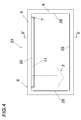
- the after Fig. 4 illustrated billboard 23 has the recess 7 - in contrast to Fig. 3 shown - on a broad side 8 of the photoconductive plate 5. It therefore forms exclusively a web 9 between the recess 7 and a broad side 8, on which also protruding into the recess 7 display 2 is applied.
- the web flank 10 initially runs parallel to the broad side 8, but then increases its cross-section steadily in the direction of the recess surface 14.
- the cross-section of the web 9 increases over the course of the recess 7 facing web flank 10 in the direction of the recess surface 14.
- the reflector 11 is also pivoted relative to the recess surface 14 positioned in the recess 7 in order to be flush with the photoconductive plate 5 can.
- the narrow end 24 of the web 9 also has a light-reflecting layer 25, wherein - as shown in Fig. 6 - also more light-reflecting layers 25 are introduced into the photoconductive plate 5 to provide a light cage.
Landscapes
- Physics & Mathematics (AREA)
- General Physics & Mathematics (AREA)
- Optics & Photonics (AREA)
- Engineering & Computer Science (AREA)
- Theoretical Computer Science (AREA)
- Microelectronics & Electronic Packaging (AREA)
- Business, Economics & Management (AREA)
- Emergency Management (AREA)
- Illuminated Signs And Luminous Advertising (AREA)
- Devices For Indicating Variable Information By Combining Individual Elements (AREA)
- Planar Illumination Modules (AREA)
Abstract
Description
- Die Erfindung betrifft eine Hinweistafel, insbesondere für eine Notbeleuchtungsanlage, mit einer hinterleuchteten Anzeige, mit mindestens einer lichtemittierenden Diode und mit einer zur Hinterleuchtung der Anzeige vorgesehenen lichtleitenden Platte, die eine durch einen Steg von einer ihrer Breitseiten getrennte Ausnehmung ausbildet, wobei die Ausnehmung wenigstens eine lichtemittierende Diode aufnimmt, die über eine an den Steg anschließende Ausnehmungsfläche mit der lichtleitenden Platte optisch verbunden ist, wobei der Steg die Anzeige wenigstens bereichsweise hinterleuchtet.
- Zur Hinterleuchtung einer Anzeige ist aus dem Stand der Technik eine lichtleitende Platte bekannt (
DE9417471 U1 ), die in einer Schmalseite eine mittige Ausnehmung mit eingesetzten LED-Leuchtmitteln aufweist, um eine an ihrer Breitseiten vorgesehene Anzeige zu beleuchten. Die sich zwischen der Ausnehmung und den Breitseiten der Platte ausbildenden Stege werden durch die eingesetzten Dioden jedoch verhältnismäßig ungleichmäßig beleuchtet. Dieser Nachteil wird zusätzlich durch die vergleichsweise schmale Abstrahlcharakteristik der Dioden verstärkt. Eine homogene Ausleuchtung bis zu den Kanten der Breitseite können derartige Vorrichtungen daher nicht gewährleisten, sodass diese trotz ihrer kompakten Bauform nur eingeschränkt verwendet werden können - insbesondere, wenn diese zur Beleuchtung als rahmenlose Hinweistafeln bzw. Sicherheitsbeleuchtungen mit Piktogrammen verwendet werden sollen. - Außerdem sind lichtleitende Platten zum Aufbau einer Hintergrundbeleuchtung von LCD Displays bekannt. So schlägt die
EP2423718A2 vor, die zur Beleuchtung der lichtleitenden Platte vorgesehenen LED in einer Ausnehmung der Platte vorzusehen, um diese damit zu schützen. DieUS2008/0049168A1 erwähnt, die optische Einkopplung der in einer Ausnehmung der lichtleitenden Platte eingesetzten LED durch Totalreflexion an den Stegen der lichtleitenden Platte zu erhöhen. - Die Erfindung hat sich daher die Aufgabe gestellt, eine Hinweistafel der eingangs geschilderten Art auf konstruktiv einfache Weise derart zu verbessern, dass trotz kompakter, rahmenloser Bauform für eine ausreichende und gleichmäßige Helligkeit über die gesamte Fläche der Breitseite gesorgt wird - und zwar insbesondere bis zu allen Kanten.
- Die Erfindung löst die gestellte Aufgabe dadurch, dass sich zur verbesserten Hinterleuchtung der Anzeige der Querschnitt des Stegs, insbesondere über den Verlauf der der Ausnehmung zugewandten Stegflanke, in Richtung der Ausnehmungsfläche zumindest bereichsweise vergrößert.
- Vergrößert sich der Querschnitt des Stegs in Richtung der Ausnehmungsfläche zumindest bereichsweise, kann eine besonders breite Eintrittsfläche für von der Platte reflektiertes Licht in den Steg und somit eine verbesserte Hinterleuchtung der Anzeige geschaffen werden - und zwar insbesondere im Bereich des Stegs. Der von der lichtleitenden Platte ausgebildete Steg kann somit auf konstruktiv einfache Weise mit einer ausreichenden Lichtmenge versorgt werden, um selbst im materialreduzierten Plattenbereich keine erkennbaren Helligkeitsunterschiede befürchtet werden müssen. Die Anzeige kann also selbst im Bereich des Stegs der Platte besonders gut ausgeleuchtet werden. Zudem kann je nach Lage des Stegs das in diesen einfallende Licht bis zur von Breit- und Schmalseite ausgebildeten Kante ausreichend geführt bzw. dorthin geleitet werden. Die stegseitige Hinterleuchtung der Anzeige kann damit verbessert werden. Somit kann eine rahmenlose Hinweistafel zur Verfügung gestellt werden, die erfindungsgemäß besonders vorteilhafte Ausleuchtungsverhältnisse aufweist. Außerdem kann durch diese Konstruktion die Verwendung einer lichtemittierenden Diode als Lichtquelle ermöglicht werden, obwohl diese eine vergleichsweise enge Abstrahlcharakteristik aufweisen. Durch die Form des lichtleitenden Stegs kann nämlich sichergestellt werden, dass zurückreflektiertes Licht der Platte selbst im Falle eines in seinem Querschnitt vergleichsweise schmalen Stegs verbessert eingefangen und sicher gelenkt wird, um damit die Platte gleichmäßig zu erhellen. Die indirekte optische Verbindung der Diode mit dem Steg kann daher für eine ausreichend hinterleuchtete Anzeige sorgen. In anderen Worten: Da sich das Diodenlicht im Wesentlichen über einen indirekten optischen Weg in den Steg einkoppelt, kann auch eine von Dioden bekannte unerwünscht fokussierte Ausleuchtung vermieden werden. Die Konstruktionsverhältnisse können vereinfacht werden, wenn sich der Querschnitt des Stegs über den Verlauf der der Ausnehmung zugewandten Stegflanke in Richtung der Ausnehmungsfläche zumindest bereichsweise vergrößert. Zudem können damit die konstruktiven Maßnahmen zur Stegausleuchtung in der Ausnehmung vorgesehen und damit auch aus dem Sichtbereich der Hinweistafel entfernt werden. Es kann sich somit sich die Möglichkeit eröffnen, eine Hinweistafel mit einer besonderen vorteilhaft hintergrundbeleuchteten Anzeige zur Verfügung zu stellen, die rahmenlos und/oder in ihren Abmessungen klein und somit auch in ihren Herstellungskosten gering ist.
- Im Allgemeinen wird erwähnt, dass es sich bei der erfindungsgemäßen Hinweistafel um beispielsweise eine Sicherheitsbeleuchtung für eine nicht näher dargestellte Notbeleuchtungsanlage handeln kann. Als Anzeige kann diese Hinweistafel ein oder mehrere Piktogramme aufweisen, die hinterleuchtet werden. Weiter wird im Allgemeinen erwähnt, dass unter Breitseite einer Platte ihre Front- und/oder Rückseite erachtet werden kann, die durch Schmalseiten voneinander beabstandet sind.
- Die Konstruktionsverhältnisse einer Hinweistafel können vereinfacht werden, wenn der Steg im Querschnitt zumindest teilweise keilförmig ausgebildet ist. Durch diese Ausbildung des Stegs werden alle obenstehenden Vorteile erreicht. Zudem kann die Reflexionswirkung der Keilfläche zur Homogenisierung der Lichtverteilung im Steg verwendet werden.
- Vorzugsweise ist die Diode mit dem Steg ausschließlich optisch indirekt verbunden, um beispielsweise durch direkte Diodenbeleuchtung bekannte nachteilige Fokussierungseffekte zu vermeiden. Die Hintergrundbeleuchtung der Anzeige kann damit weiter verbessert werden.
- Verläuft die Ausnehmungsfläche senkrecht zur Breitseite, können die Konstruktionsbedingungen der Hinweistafel noch weiter vereinfachen.
- Weist die Hinweistafel einen Reflektor auf, der an den Steg wenigstens bereichsweise anschließt, kann dies zur gleichmäßig hellen Ausleuchtung der gesamten Breitseite der Platte beitragen. Zudem kann ein Reflektor genutzt werden, von Dioden emittiertes Licht verbessert zu lenken, womit auch erreicht werden kann, dass Licht in seiner Intensität gleichmäßiger in eine lichtleitende Platte einfällt. Mithilfe eines Reflektors kann des Weiteren standfest verhindert werden, dass Licht direkt von lichtemittierenden Dioden in Steg einfällt, was den Steg unerwünscht stark ausleuchten kann. Zudem können die eingesetzten Dioden durch den Reflektor optisch in den Hintergrund treten - bzw. in gewissem Ausmaß nicht einsehbar sein. Ein mit einem Reflektor versehener Steg kann daher nicht nur für besonders vorteilhafte Beleuchtungsverhältnisse an der Anzeige sorgen, sondern auch eine kompakte und rahmenlose Bauweise der Hinweistafel erleichtern.
- Konstruktive Einfachheit und hohe Standfestigkeit können sich ergeben, wenn der Reflektor mindestens eine Diode trägt. Vorteilhaft kann der Reflektor metallisch ausgebildet und mit mindestens einer Diode wärmeleitend verbundenen sein, um die Diode damit zu kühlen. So kann die Lebensdauer der Diode erhöht werden, zumal mithilfe des als Kühlkörper wirkenden Reflektors für eine gleichmäßige Temperaturverteilung gesorgt werden kann, wenn mehrere Dioden zur Hinterleuchtung der Anzeige verwendet werden.
- Weist die Hinweistafel einen dem Reflektor vorstehende Platine auf, auf der mindestens eine Diode befestigt ist und die einen Anschlag zur Positionierung der Diode in der Ausnehmung ausbildet, können konstruktiv einfache Voraussetzungen zur Herstellung der Hinweistafel geschaffen werden. Des Weiteren können durch diesen Anschlag die Wartung eines Leuchtmittels bzw. von Dioden vereinfacht werden. Eine besonders vorteilhafte Ausleuchtung einer Hinweistafel kann erreicht werden, wenn der Reflektor eine Blende zur Beschränkung der direkten Lichteinstrahlung mindestens einer Diode in den Steg ausbildet. Dazu kann vorgesehen sein, dass der Reflektor die gesamte ausnehmungsseitige Stegfläche bedeckt. Erfindungsgemäß kann dieser Vorteil in Verbindung mit dem bereits genannten Vorteil der Reflexion von Licht im Steg zu einer besonders gut und homogen ausgeleuchteten Hinweistafel führen.
- Konstruktiv einfach kann der Reflektor einteilig und U-förmig ausgebildet sein und eine gegenüber seinen beiden Schenkeln zurückversetzte Aufnahme für mindestens eine Diode ausbilden. So können die Schenkel als Blend- und/oder Sichtschutz für die im Reflektor verdeckt angeordnete Diode bzw. Dioden wirken.
- Wärmedehnungseffekte können auf einfache Weise kompensiert werden, indem der Reflektor von der Ausnehmungsfläche beabstandet angeordnet ist. So steht dem Reflektor in Richtung des Bodens der Ausnehmung eine Möglichkeit zur thermischen Ausdehnung zur Verfügung, was die Standfestigkeit der Hinweistafel erhöhen kann.
- Eine einfache Zugänglichkeit zu den Dioden kann geschaffen werden, wenn die Ausnehmung in einer Schmalseite der lichtleitenden Platte vorgesehen ist. Zudem kann mit solch einer Konstruktion eine gleichmäßige Ausleuchtung bis zum Rand der lichtleitenden Platte ergeben. Insbesondere deren mittige Anordnung kann für eine gleichmäßige Helligkeitsverteilung auf der Breitseite/den Breiseiten der lichtleitenden Platte sorgen.
- Die Konstruktionsverhältnisse zur Hinterleuchtung von Anzeigen über beide Breitseiten einer lichtleitenden Platte können vereinfacht werden, indem die Ausnehmung durch je einen Steg von der jeweiligen Breitseite getrennt ist und der Reflektor an beide Stege wenigstens bereichsweise anschließt.
- Die Ausnehmung kann unter Erreichung vorgenannter Vorteile auch in einer der Breitseiten der lichtleitenden Platte vorgesehen sein, um Licht der Diode in die lichtleitende Platte einzukoppeln.
- Eine Auskopplung von Licht über den Steg hinaus kann auf konstruktiv einfache Weise verhindert werden, wenn das schmale Ende des Stegs eine lichtreflektierende Schicht aufweist.
- Weist wenigstens eine Breitseite der lichtleitenden Platte zumindest auf Höhe des Stegs eine streuende Oberflächenkontur auf, kann die Lichtabstrahlung der Platte gezielt verändert und eingestellt werden, um damit eventuelle Helligkeitsunterschiede weiter auszugleichen. Eine besonders gleichmäßige Hinterleuchtung der Anzeige der erfindungsgemäßen Hinweistafel kann so sichergestellt werden.
- Ist wenigstens eine Breitseite der lichtleitenden Platte mit einer die Anzeige aufweisenden lichtdurchlässigen Anzeigeplatte bündig abgedeckt, kann der Steg zum Tragen der Anzeige vergleichsweise schlank ausgeführt werden, da die mechanischen Belastungen auf einen Steg verringert werden können. Ein derartiger Schutz der lichtleitenden Platte kann erfindungsgemäß zur Ausbildung einer schlanken Hinweistafel genutzt werden und in weiterer Folge zu einer kompakten Bauweise der Hinweistafel führen. Diese kompakte Bauweise kann auch erreicht werden, wenn wenigstens eine Breitseite der lichtleitenden Platte mit der Anzeige bündig abgedeckt ist.
- In den Figuren ist beispielsweise der Erfindungsgegenstand anhand mehrerer Ausführungsbeispiele näher dargestellt. Es zeigen
- Fig. 1.
- eine teilweise aufgerissene Ansicht auf eine Breitseite einer Hinweistafel nach einem ersten Ausführungsbeispiel,
- Fig. 2
- eine Draufsicht auf eine Schmalseite der Hinweistafel nach
Fig. 1 , - Fig. 3
- eine abgerissene und vergrößerte Schnittansicht nach III-III der
Fig. 1 , - Fig. 4
- eine Ansicht auf die rückseitige Breitseite einer weiteren Hinweistafel nach einem zweiten Ausführungsbeispiel und
- Fig. 5
- eine abgerissene und vergrößerte Schnittansicht nach V-V der
Fig. 4 . - Die nach
Fig. 1 beispielsweise nach einem ersten Ausführungsbeispiel dargestellte Hinweistafel 1 ist Teil einer nicht näher dargestellten Sicherheitsbeleuchtung und trägt als Anzeige 2 beispielsweise ein grünes Piktogramm mit einem Pfeil. Die Anzeige 2 ist im Hintergrund beleuchtet, wofür lichtemittierende Dioden 3 (LEDs) vorgesehen sind. Die Dioden 3 können auch mit einem nicht näher dargestellten Gehäuse und/oder mit einer nicht näher dargestellten Linse versehen sein. Alle Dioden 3 sind auf einer Platine 4 befestigt und über diese Platine 4 elektrisch verbunden. Die Dioden 3 dienen zur Erhellung einer lichtleitenden Platte 5, insbesondere zur Hinterleuchtung der Anzeige 2 über die Breitseite 8 der Platte 5. Für eine vorteilhafte Einkopplung von Licht weist die Platte 5 an ihrer oberen Schmalseite 6 eine Ausnehmung 7 auf. In diese Ausnehmung 7 sind die Dioden 3 eingesetzt. Die Ausnehmung 7 ist in der Platte 5 an ihrer oberen Schmalseite 6 mittig vorgesehen, sodass die Ausnehmung 7 beidseitig durch jeweils einen Steg 9 von den Breitseiten 8 der Platte 5 getrennt ist. Wie insbesondere derFig. 2 zu entnehmen, weist die Platte 5 nun in den Bereichen der Stege 9 verminderte Materialstärken auf, was eine homogen helle Ausleuchtung der Breitseite 8 bzw. der im Bereich des Stegs 9 vorgesehenen Anzeige 2 erschwert. - Um dennoch eine homogene und helle Ausleuchtung der Breitseite 8 zu schaffen, vergrößert sich der Querschnitt des Stegs 9 in Richtung der Ausnehmungsfläche 14 zumindest bereichsweise. Dabei sind die Dioden 3 über die Ausnehmungsfläche 14 mit der lichtleitenden Platte 5 optisch verbunden, wie dies im Detail der
Fig. 3 entnommen werden kann. Durch diese Form des Stegs 9 wird die Anzeige 2 in diesem Bereich im Wesentlichen mit indirektem Diodenlicht beleuchtet, indem sich zunächst direkt über die Ausnehmungsfläche 14 in die Platte 5 eingekoppeltes Diodenlicht durch Reflexion im Steg zur Hintergrundbeleuchtung sammelt. Eine unerwünschte direkte Einkopplung von Diodenlicht in den Steg 9 kann daher unterbleiben, was einer gleichmäßigen Hintergrundbeleuchtung der Anzeige 2 förderlich ist. Erfindungsgemäß kann daher die gesamte Breiteseite 8 der Platte 5 bedenkenlos - aufgrund gleichmäßiger und allem auch vollflächiger - Ausleuchtung mit der damit im Hintergrund zu beleuchteten Anzeige 2 versehen werden. - Konstruktiv einfach wird die Stegform ausgebildet, indem sich der Querschnitt des Stegs 9 über den Verlauf der der Ausnehmung 7 zugewandten Stegflanke 10 in Richtung der Ausnehmungsfläche 14 stetig vergrößert. Diese Maßnahme kann die Breitseite 8 frei von diesbezüglichen Konstruktionsmerkmalen halten und damit beispielsweise Planheit garantieren.
- Zudem ist - diese Vorteile ergänzend - an den der Ausnehmung 7 zugewandten Stegflanken 10 der Stege 9 je ein Reflektor 11 vorgesehen. Die Reflektoren 11 schließen an den Steg 9 an, womit durch die Stege 9 ein in der Führung von Licht definierbarer Lichtleiter geschaffen wird, der sich beidseitig der Ausnehmung 7 erstreckt und selbst in diesen materialverminderten Bereichen der Platte 5 die Helligkeit der Hinterleuchtung an die anderen Plattenbereiche verbessert angleicht. Da nun eine Anzeige 2 bis zu den Kanten 12 der Breitseite 8 gleichmäßig ausgeleuchtet werden kann, ist auch ein Rahmen im Bereich der Dioden 3 nicht mehr erforderlich. Die dargestellte erfindungsgemäße Hinweistafel 1 ermöglicht daher eine kompakte und konstruktiv einfache Ausführung.
- Als Reflektor 11 ist beispielsweise ein Spiegel, eine spiegelnde Folie oder eine auf den Steg 9 aufgedampfte Spiegelschicht vorstellbar. Beispielsweise kann hierfür ein metallischer Körper verwendet werden, der im thermischen Verbund mit den Dioden 3 auch zu deren Kühlung beitragen kann.
- Konstruktiv einfach weisen die Stege 9 im Querschnitt eine Keilform auf und verläuft die Ausnehmungsfläche 14, über die die Dioden 3 mit der lichtleitenden Platte 5 optisch verbunden sind, senkrecht zur Breitseite 8.
- Nach
Fig. 1 ist zu erkennen, dass die Hauptachse 13 der Abstrahlung der Dioden 3 parallel zur Breitseite 8 der Platte 5 verläuft. Um eine direkte Lichteinstrahlung in die Stege 9 durch eine eventuelle Nebenabstrahlung der Dioden 3 weitgehend zu unterbinden, bildet der Reflektor 11 eine Blende aus. Zu diesem Zweck ragt der Reflektor 11 deutlich tiefer in die Ausnehmung 7, als dies bei den Dioden 3 der Fall ist. Eventuelle Fokussierungspunkte der Dioden 3 im Bereich der Stege 9 sind dadurch auf konstruktiv einfache Weise zu verhindern. - Die konstruktive Ausgestaltung der dem Reflektor 11 vorstehenden Platine 4 wird genutzt, indem diese einen Anschlag 21 zur Positionierung der Dioden 3 bzw. des Kühlkörpers in der Ausnehmung 7 aufweist. Der mit der Platine 4 verbundene Reflektor 11 kann so die Lage der Dioden 3 an der Schmalseite 6 der Platte 5 positionsgenau festlegen. Dieser so fix eingestellte Abstand der Dioden 3 zum den Boden bildenden Ausnehmungsfläche 14 führt zu konstanten Beleuchtungsverhältnissen bei gleichmäßig heller Ausleuchtung der Anzeige 2.
- Die Breitseiten 8 der lichtleitenden Platte 5 weisen Rillen 15 auf, um damit der Platte 5 eine streuende Oberflächenkontur 16 zu geben. Eine andere Geometrie bzw. Struktur zur Ausbildung einer Oberflächenkontur 16 ist vorstellbar, was jedoch nicht näher dargestellt worden ist. Auf diese Weise können Helligkeitsunterschiede weiter ausgeglichen werden. Solch eine streuende Oberflächenkontur 16 ist auch im Bereich der Stege 9 vorstellbar. Anstatt oder zusätzlich zu Rillen 15 ist es auch vorstellbar, die Platte 5 mit anders geformten Oberflächenkonturen zu versehen.
- An den Breitseiten 8 der Platte 5 sind jeweils Anzeigeplatten 17 vorgesehen, die durch die Platte 5 hintergrundbeleuchtet werden. Die Anzeigeplatten 17 decken die lichtleitende Platte 5 bündig ab und schaffen so eine besonders schlanke, rahmenlose Hinweistafel 1, in der die Platte 5 vor Beschädigungen geschützt werden kann.
- Nach
Fig. 3 ist der Reflektor 11 U-förmig geformt. Der in die mittige Ausnehmung 7 eingesetzte Reflektor 11 ist als einteiliger Kühlkörper mit obenliegenden Kühlrippen 20 ausgebildet. Die Schenkel 18 des Reflektors 11 liegen an den Stegflanken 10 der lichtleitenden Platte 5 an. Zudem bildet der Reflektor 11 eine gegenüber seinen beiden Schenkeln 18 zurückversetzte Aufnahme 19 für die Dioden 3 aus. Die auf der Platine 4 vorgesehenen Dioden 3 können so im Reflektor 11 versenkt vorgesehen werden. Somit ist eine wärmeleitende Verbindung sichergestellt, womit der Reflektor 11 als kühlender Träger der Dioden 3 bzw. der Platine 4 der Dioden 3 aber auch als Abschirmung der Dioden vor deren direkten Einsehbarkeit dienen kann. Eine konstruktiv besonders einfache Hinweistafel 1 ist sohin geschaffen. - Zudem ist der
Fig. 3 zu entnehmen, dass sich der Steg 9 der Schmalseite 6 zulaufend verjüngt, was zu Ausnehmung 7 mit V-förmig zulaufenden Stegflanken 10 führt. Damit kann der Boden 14 der Ausnehmung 7 klein gehalten und eine verbesserte Lichtkopplung in den beiden Stegen 9 erreicht werden. Die Ausgestaltung beider Stege 9 kann beispielsweise in die Platte 5 gefräst werden. - Des Weiteren ist auch der
Fig. 3 zu entnehmen, dass der Reflektor 11 von der Ausnehmungsfläche 14 beabstandet angeordnet ist. Dieser Abstand 22 dient insbesondere in Hinblick auf mögliche Wärmedehnungseffekte. - Die nach
Fig. 4 dargestellte Hinweistafel 23 weist die Ausnehmung 7 - zum Unterschied zur nachFig. 3 dargestellten - auf einer Breitseite 8 der lichtleitenden Platte 5 auf. Es bildet sich daher ausschließlich ein Steg 9 zwischen der Ausnehmung 7 und einer Breitseite 8 aus, auf welcher auch die in die Ausnehmung 7 vorragende Anzeige 2 aufgebracht ist. - Die Stegflanke 10 verläuft zunächst parallel zur Breitseite 8, vergrößert jedoch danach ihren Querschnitt stetig in Richtung der Ausnehmungsfläche 14. Auch hier vergrößert sich der Querschnitt des Stegs 9 über den Verlauf der der Ausnehmung 7 zugewandten Stegflanke 10 in Richtung der Ausnehmungsfläche 14. So wird ein Flaschenhals in der optischen Anbindung des Stegs vermieden. Auf diese Weise kann eine ausreichende Menge Licht der Dioden 3 über die Ausnehmungsfläche 14 in die lichtleitende Platte 5 eingekoppelt werden und dem Steg 9 zu dessen homogenen Ausleuchtung indirekt zugeführt werden. Der Reflektor 11 ist zudem gegenüber der Ausnehmungsfläche 14 verschwenkt in der Ausnehmung 7 positioniert, um bündig mit der lichtleitenden Platte 5 abschließen zu können.
- Das schmale Ende 24 des Stegs 9 weist zudem eine lichtreflektierende Schicht 25 auf, wobei - wie in Fig. 6 dargestellt - zudem weitere lichtreflektierende Schichten 25 in die lichtleitende Platte 5 eingebracht sind, um einen Lichtkäfig zu schaffen.
Claims (15)
- Hinweistafel, insbesondere für eine Notbeleuchtungsanlage, mit einer hinterleuchteten Anzeige (2), mit mindestens einer lichtemittierenden Diode (3) und mit einer zur Hinterleuchtung der Anzeige (2) vorgesehenen lichtleitenden Platte (5), die eine durch einen Steg (9) von einer ihrer Breitseiten (8) getrennte Ausnehmung (7) ausbildet, wobei die Ausnehmung (7) wenigstens eine lichtemittierende Diode (3) aufnimmt, die über eine an den Steg (9) anschließende Ausnehmungsfläche (14) mit der lichtleitenden Platte (5) optisch verbunden ist, wobei der Steg (9) die Anzeige (2) wenigstens bereichsweise hinterleuchtet, dadurch gekennzeichnet, dass sich zur verbesserten Hinterleuchtung der Anzeige (2) der Querschnitt des Stegs (9), insbesondere über den Verlauf der der Ausnehmung (7) zugewandten Stegflanke (10), in Richtung der Ausnehmungsfläche (14) zumindest bereichsweise vergrößert.
- Hinweistafel nach Anspruch 1, dadurch gekennzeichnet, dass der Steg (9) im Querschnitt zumindest teilweise keilförmig ausgebildet ist.
- Hinweistafel nach Anspruch 1 oder 2, dadurch gekennzeichnet, dass die Diode (3) mit dem Steg (9) ausschließlich optisch indirekt verbunden ist.
- Hinweistafel nach einem der Anspruch 1, 2 oder 3, dadurch gekennzeichnet, dass die Hinweistafel (1, 23) einen Reflektor (11) aufweist, der an den Steg (9) wenigstens bereichsweise anschließt.
- Hinweistafel nach Anspruch 4, dadurch gekennzeichnet, dass der insbesondere metallische Reflektor (11) mindestens eine Diode (3) trägt und zu deren Kühlung mit dieser wärmeleitend verbundenen ist.
- Hinweistafel nach Anspruch 4 oder 5, dadurch gekennzeichnet, dass die Hinweistafel (1, 23) eine dem Reflektor (11) vorstehende Platine (4) aufweist, auf der mindestens eine Diode (3) befestigt ist und die einen Anschlag (21) zur Positionierung der Diode (3) in der Ausnehmung (7) ausbildet.
- Hinweistafel nach Anspruch 4, 5 oder 6, dadurch gekennzeichnet, dass der Reflektor (11) eine Blende zur Beschränkung der direkten Lichteinstrahlung mindestens einer Diode (3) in den Steg (9) ausbildet.
- Hinweistafel nach einem der Ansprüche 4 bis 7, dadurch gekennzeichnet, dass der Reflektor (11) einteilig und U-förmig ausgebildet ist und eine gegenüber seinen beiden Schenkeln (18) zurückversetzte Aufnahme (19) für mindestens eine Diode (3) ausbildet.
- Hinweistafel nach einem der Ansprüche 4 bis 8, dadurch gekennzeichnet, dass der Reflektor (11) von der Ausnehmungsfläche (14) beabstandet angeordnet ist.
- Hinweistafel nach einem der Ansprüche 1 bis 9, dadurch gekennzeichnet, die Ausnehmung (7) in einer Schmalseite (6) der lichtleitenden Platte (5), insbesondere mittig, vorgesehen ist.
- Hinweistafel nach Anspruch 10, dadurch gekennzeichnet, dass die Ausnehmung (7) durch je einen Steg (9) von der jeweiligen Breitseite (8) getrennt ist und dass der Reflektor (11) an beide Stege (9) wenigstens bereichsweise anschließt.
- Hinweistafel nach einem der Ansprüche 1 bis 9, dadurch gekennzeichnet, die Ausnehmung (7) in einer der Breitseiten (8) der lichtleitenden Platte (5) vorgesehen ist.
- Hinweistafel nach Anspruch 12, dadurch gekennzeichnet, dass das schmale Ende (24) des Stegs (9) eine lichtreflektierende Schicht (25) aufweist.
- Hinweistafel nach einem der Ansprüche 1 bis 13, dadurch gekennzeichnet, dass wenigstens eine Breitseite (8) der lichtleitenden Platte (3) zumindest auf Höhe des Stegs (9) eine streuende Oberflächenkontur (16) aufweist.
- Hinweistafel nach einem der Ansprüche 1 bis 14, dadurch gekennzeichnet, dass wenigstens eine Breitseite (8) der lichtleitenden Platte (3) mit der Anzeige (2), insbesondere mit einer die Anzeige (2) aufweisenden lichtdurchlässigen Anzeigeplatte (17), bündig abgedeckt ist.
Applications Claiming Priority (1)
| Application Number | Priority Date | Filing Date | Title |
|---|---|---|---|
| ATA50044/2013A AT513894B1 (de) | 2013-01-22 | 2013-01-22 | Hinweistafel, insbesondere für eine Notbeleuchtungsanlage |
Publications (3)
| Publication Number | Publication Date |
|---|---|
| EP2757545A2 true EP2757545A2 (de) | 2014-07-23 |
| EP2757545A3 EP2757545A3 (de) | 2016-07-27 |
| EP2757545B1 EP2757545B1 (de) | 2019-03-20 |
Family
ID=49989588
Family Applications (1)
| Application Number | Title | Priority Date | Filing Date |
|---|---|---|---|
| EP14152214.4A Active EP2757545B1 (de) | 2013-01-22 | 2014-01-22 | Hinweistafel, insbesondere für eine Notbeleuchtungsanlage |
Country Status (2)
| Country | Link |
|---|---|
| EP (1) | EP2757545B1 (de) |
| AT (1) | AT513894B1 (de) |
Family Cites Families (7)
| Publication number | Priority date | Publication date | Assignee | Title |
|---|---|---|---|---|
| DE29704879U1 (de) * | 1997-03-19 | 1997-09-11 | Halfmann Horst | Leuchtschild |
| DE19942513A1 (de) * | 1999-09-07 | 2001-03-08 | Gerhard Karl | Leuchtkörper für durchleuchtungsfähige Bilder |
| US7616849B1 (en) * | 2005-03-23 | 2009-11-10 | Simon Jerome H | Illuminating devices including uniform light distribution, multiple light sources, and multiple types of light sources |
| KR100826401B1 (ko) * | 2005-12-02 | 2008-05-02 | 삼성전기주식회사 | Led 백라이트 장치 |
| JP4765837B2 (ja) * | 2006-08-23 | 2011-09-07 | ソニー株式会社 | バックライト装置及び液晶表示装置 |
| WO2008097472A2 (en) * | 2007-02-03 | 2008-08-14 | Illuminer, Inc. | Light emitting diode modules for illuminated panels |
| TW201209480A (en) * | 2010-08-25 | 2012-03-01 | Young Lighting Technology Corp | Light guide plate and light source module |
-
2013
- 2013-01-22 AT ATA50044/2013A patent/AT513894B1/de active
-
2014
- 2014-01-22 EP EP14152214.4A patent/EP2757545B1/de active Active
Also Published As
| Publication number | Publication date |
|---|---|
| AT513894B1 (de) | 2016-01-15 |
| AT513894A1 (de) | 2014-08-15 |
| EP2757545B1 (de) | 2019-03-20 |
| EP2757545A3 (de) | 2016-07-27 |
Similar Documents
| Publication | Publication Date | Title |
|---|---|---|
| DE10258465B4 (de) | Beleuchtungsvorrichtung für ein Kennzeichenschild | |
| DE102017124429B4 (de) | Beleuchtungsvorrichtung, Verfahren zur Herstellung einer Beleuchtungsvorrichtung und Lichtverteiler | |
| EP2738447B1 (de) | Regalbeleuchtungsvorrichtung | |
| DE102013212353B4 (de) | Kraftfahrzeugbeleuchtungseinrichtung mit einer eine Einkoppeloptik und eine Transport- und Umformoptik aufweisenden Lichtleiteranordnung | |
| EP3190332B1 (de) | Beleuchtungseinheit für ein kraftfahrzeug | |
| EP1839539A2 (de) | Regalbeleuchtungselement | |
| EP0533301B1 (de) | Hinweisleuchte | |
| EP2071227A1 (de) | Wand- und/oder Deckenleuchte | |
| EP3015761A1 (de) | Leuchtenbaugruppe mit optischem element | |
| DE102004046256A1 (de) | Oberflächenleuchtsystem | |
| DE10001412C2 (de) | Beleuchtungseinheit | |
| DE202008002873U1 (de) | Lichtmodul für Raum- und Flächenausleuchtung | |
| EP2556287B1 (de) | Anordnung zur lichtabgabe mit mehreren lichtquellen und transparentem lichtabstrahlelement | |
| DE102014004472A1 (de) | Leuchtmodul aufweisend ein optisches Element | |
| EP2404289B1 (de) | Leuchtvorrichtung mit einem grundkörper aus lichtdurchlässigem material | |
| DE102008016675B4 (de) | Leuchtanordnung mit einem Lichtleiter und Leuchtdioden | |
| EP2760009B1 (de) | Hinweistafel, insbesondere für eine Notbeleuchtungsanlage | |
| EP2757545B1 (de) | Hinweistafel, insbesondere für eine Notbeleuchtungsanlage | |
| EP0978683A1 (de) | OPtishe Anzeigevorrichtung | |
| EP1696260B1 (de) | Flüssigkristallanzeigeeinrichtung sowie Flüssigkristallanzeigeanordnung mit einer Mehrzahl von solchen Flüssigkristallanzeigeeinrichtungen | |
| CH709635A2 (de) | Leuchtrahmen. | |
| DE102011016407A1 (de) | Kennzeichnungsbeleuchtung für ein Kraftfahrzeug | |
| DE202005001507U1 (de) | Oberflächenleuchtsystem | |
| EP4481718A1 (de) | Sicherheits- und/oder rettungszeichenleuchte | |
| AT413612B (de) | Beleuchtete hinweistafel |
Legal Events
| Date | Code | Title | Description |
|---|---|---|---|
| PUAI | Public reference made under article 153(3) epc to a published international application that has entered the european phase |
Free format text: ORIGINAL CODE: 0009012 |
|
| 17P | Request for examination filed |
Effective date: 20140122 |
|
| AK | Designated contracting states |
Kind code of ref document: A2 Designated state(s): AL AT BE BG CH CY CZ DE DK EE ES FI FR GB GR HR HU IE IS IT LI LT LU LV MC MK MT NL NO PL PT RO RS SE SI SK SM TR |
|
| AX | Request for extension of the european patent |
Extension state: BA ME |
|
| RIN1 | Information on inventor provided before grant (corrected) |
Inventor name: DER ERFINDER HAT AUF SEINE NENNUNG VERZICHTET. |
|
| PUAL | Search report despatched |
Free format text: ORIGINAL CODE: 0009013 |
|
| AK | Designated contracting states |
Kind code of ref document: A3 Designated state(s): AL AT BE BG CH CY CZ DE DK EE ES FI FR GB GR HR HU IE IS IT LI LT LU LV MC MK MT NL NO PL PT RO RS SE SI SK SM TR |
|
| AX | Request for extension of the european patent |
Extension state: BA ME |
|
| RIC1 | Information provided on ipc code assigned before grant |
Ipc: G09F 13/22 20060101ALN20160617BHEP Ipc: G02B 6/00 20060101ALI20160617BHEP Ipc: G09F 13/04 20060101ALN20160617BHEP Ipc: G08B 7/06 20060101ALI20160617BHEP Ipc: G09F 13/18 20060101AFI20160617BHEP |
|
| STAA | Information on the status of an ep patent application or granted ep patent |
Free format text: STATUS: REQUEST FOR EXAMINATION WAS MADE |
|
| R17P | Request for examination filed (corrected) |
Effective date: 20170127 |
|
| RBV | Designated contracting states (corrected) |
Designated state(s): AL AT BE BG CH CY CZ DE DK EE ES FI FR GB GR HR HU IE IS IT LI LT LU LV MC MK MT NL NO PL PT RO RS SE SI SK SM TR |
|
| GRAP | Despatch of communication of intention to grant a patent |
Free format text: ORIGINAL CODE: EPIDOSNIGR1 |
|
| STAA | Information on the status of an ep patent application or granted ep patent |
Free format text: STATUS: GRANT OF PATENT IS INTENDED |
|
| RIC1 | Information provided on ipc code assigned before grant |
Ipc: G08B 7/06 20060101ALI20180222BHEP Ipc: G09F 13/22 20060101ALN20180222BHEP Ipc: G09F 13/04 20060101ALN20180222BHEP Ipc: G09F 13/18 20060101AFI20180222BHEP Ipc: G02B 6/00 20060101ALI20180222BHEP |
|
| INTG | Intention to grant announced |
Effective date: 20180316 |
|
| GRAS | Grant fee paid |
Free format text: ORIGINAL CODE: EPIDOSNIGR3 |
|
| GRAJ | Information related to disapproval of communication of intention to grant by the applicant or resumption of examination proceedings by the epo deleted |
Free format text: ORIGINAL CODE: EPIDOSDIGR1 |
|
| GRAL | Information related to payment of fee for publishing/printing deleted |
Free format text: ORIGINAL CODE: EPIDOSDIGR3 |
|
| STAA | Information on the status of an ep patent application or granted ep patent |
Free format text: STATUS: REQUEST FOR EXAMINATION WAS MADE |
|
| INTC | Intention to grant announced (deleted) | ||
| RIC1 | Information provided on ipc code assigned before grant |
Ipc: G09F 13/18 20060101AFI20180814BHEP Ipc: G08B 7/06 20060101ALI20180814BHEP Ipc: G09F 13/22 20060101ALN20180814BHEP Ipc: G02B 6/00 20060101ALI20180814BHEP Ipc: G09F 13/04 20060101ALN20180814BHEP |
|
| GRAP | Despatch of communication of intention to grant a patent |
Free format text: ORIGINAL CODE: EPIDOSNIGR1 |
|
| STAA | Information on the status of an ep patent application or granted ep patent |
Free format text: STATUS: GRANT OF PATENT IS INTENDED |
|
| RIC1 | Information provided on ipc code assigned before grant |
Ipc: G09F 13/22 20060101ALN20180821BHEP Ipc: G02B 6/00 20060101ALI20180821BHEP Ipc: G09F 13/18 20060101AFI20180821BHEP Ipc: G09F 13/04 20060101ALN20180821BHEP Ipc: G08B 7/06 20060101ALI20180821BHEP |
|
| INTG | Intention to grant announced |
Effective date: 20180925 |
|
| GRAA | (expected) grant |
Free format text: ORIGINAL CODE: 0009210 |
|
| STAA | Information on the status of an ep patent application or granted ep patent |
Free format text: STATUS: THE PATENT HAS BEEN GRANTED |
|
| AK | Designated contracting states |
Kind code of ref document: B1 Designated state(s): AL AT BE BG CH CY CZ DE DK EE ES FI FR GB GR HR HU IE IS IT LI LT LU LV MC MK MT NL NO PL PT RO RS SE SI SK SM TR |
|
| REG | Reference to a national code |
Ref country code: GB Ref legal event code: FG4D Free format text: NOT ENGLISH |
|
| REG | Reference to a national code |
Ref country code: CH Ref legal event code: EP |
|
| REG | Reference to a national code |
Ref country code: DE Ref legal event code: R096 Ref document number: 502014011161 Country of ref document: DE |
|
| REG | Reference to a national code |
Ref country code: AT Ref legal event code: REF Ref document number: 1111310 Country of ref document: AT Kind code of ref document: T Effective date: 20190415 |
|
| REG | Reference to a national code |
Ref country code: IE Ref legal event code: FG4D Free format text: LANGUAGE OF EP DOCUMENT: GERMAN |
|
| REG | Reference to a national code |
Ref country code: CH Ref legal event code: NV Representative=s name: ISLER AND PEDRAZZINI AG, CH |
|
| REG | Reference to a national code |
Ref country code: NL Ref legal event code: MP Effective date: 20190320 |
|
| PG25 | Lapsed in a contracting state [announced via postgrant information from national office to epo] |
Ref country code: SE Free format text: LAPSE BECAUSE OF FAILURE TO SUBMIT A TRANSLATION OF THE DESCRIPTION OR TO PAY THE FEE WITHIN THE PRESCRIBED TIME-LIMIT Effective date: 20190320 Ref country code: NO Free format text: LAPSE BECAUSE OF FAILURE TO SUBMIT A TRANSLATION OF THE DESCRIPTION OR TO PAY THE FEE WITHIN THE PRESCRIBED TIME-LIMIT Effective date: 20190620 Ref country code: FI Free format text: LAPSE BECAUSE OF FAILURE TO SUBMIT A TRANSLATION OF THE DESCRIPTION OR TO PAY THE FEE WITHIN THE PRESCRIBED TIME-LIMIT Effective date: 20190320 Ref country code: LT Free format text: LAPSE BECAUSE OF FAILURE TO SUBMIT A TRANSLATION OF THE DESCRIPTION OR TO PAY THE FEE WITHIN THE PRESCRIBED TIME-LIMIT Effective date: 20190320 |
|
| REG | Reference to a national code |
Ref country code: LT Ref legal event code: MG4D |
|
| PG25 | Lapsed in a contracting state [announced via postgrant information from national office to epo] |
Ref country code: NL Free format text: LAPSE BECAUSE OF FAILURE TO SUBMIT A TRANSLATION OF THE DESCRIPTION OR TO PAY THE FEE WITHIN THE PRESCRIBED TIME-LIMIT Effective date: 20190320 Ref country code: RS Free format text: LAPSE BECAUSE OF FAILURE TO SUBMIT A TRANSLATION OF THE DESCRIPTION OR TO PAY THE FEE WITHIN THE PRESCRIBED TIME-LIMIT Effective date: 20190320 Ref country code: BG Free format text: LAPSE BECAUSE OF FAILURE TO SUBMIT A TRANSLATION OF THE DESCRIPTION OR TO PAY THE FEE WITHIN THE PRESCRIBED TIME-LIMIT Effective date: 20190620 Ref country code: HR Free format text: LAPSE BECAUSE OF FAILURE TO SUBMIT A TRANSLATION OF THE DESCRIPTION OR TO PAY THE FEE WITHIN THE PRESCRIBED TIME-LIMIT Effective date: 20190320 Ref country code: LV Free format text: LAPSE BECAUSE OF FAILURE TO SUBMIT A TRANSLATION OF THE DESCRIPTION OR TO PAY THE FEE WITHIN THE PRESCRIBED TIME-LIMIT Effective date: 20190320 |
|
| PG25 | Lapsed in a contracting state [announced via postgrant information from national office to epo] |
Ref country code: IT Free format text: LAPSE BECAUSE OF FAILURE TO SUBMIT A TRANSLATION OF THE DESCRIPTION OR TO PAY THE FEE WITHIN THE PRESCRIBED TIME-LIMIT Effective date: 20190320 Ref country code: SK Free format text: LAPSE BECAUSE OF FAILURE TO SUBMIT A TRANSLATION OF THE DESCRIPTION OR TO PAY THE FEE WITHIN THE PRESCRIBED TIME-LIMIT Effective date: 20190320 Ref country code: EE Free format text: LAPSE BECAUSE OF FAILURE TO SUBMIT A TRANSLATION OF THE DESCRIPTION OR TO PAY THE FEE WITHIN THE PRESCRIBED TIME-LIMIT Effective date: 20190320 Ref country code: ES Free format text: LAPSE BECAUSE OF FAILURE TO SUBMIT A TRANSLATION OF THE DESCRIPTION OR TO PAY THE FEE WITHIN THE PRESCRIBED TIME-LIMIT Effective date: 20190320 Ref country code: RO Free format text: LAPSE BECAUSE OF FAILURE TO SUBMIT A TRANSLATION OF THE DESCRIPTION OR TO PAY THE FEE WITHIN THE PRESCRIBED TIME-LIMIT Effective date: 20190320 Ref country code: CZ Free format text: LAPSE BECAUSE OF FAILURE TO SUBMIT A TRANSLATION OF THE DESCRIPTION OR TO PAY THE FEE WITHIN THE PRESCRIBED TIME-LIMIT Effective date: 20190320 Ref country code: PT Free format text: LAPSE BECAUSE OF FAILURE TO SUBMIT A TRANSLATION OF THE DESCRIPTION OR TO PAY THE FEE WITHIN THE PRESCRIBED TIME-LIMIT Effective date: 20190720 Ref country code: AL Free format text: LAPSE BECAUSE OF FAILURE TO SUBMIT A TRANSLATION OF THE DESCRIPTION OR TO PAY THE FEE WITHIN THE PRESCRIBED TIME-LIMIT Effective date: 20190320 |
|
| PG25 | Lapsed in a contracting state [announced via postgrant information from national office to epo] |
Ref country code: SM Free format text: LAPSE BECAUSE OF FAILURE TO SUBMIT A TRANSLATION OF THE DESCRIPTION OR TO PAY THE FEE WITHIN THE PRESCRIBED TIME-LIMIT Effective date: 20190320 Ref country code: PL Free format text: LAPSE BECAUSE OF FAILURE TO SUBMIT A TRANSLATION OF THE DESCRIPTION OR TO PAY THE FEE WITHIN THE PRESCRIBED TIME-LIMIT Effective date: 20190320 |
|
| PG25 | Lapsed in a contracting state [announced via postgrant information from national office to epo] |
Ref country code: IS Free format text: LAPSE BECAUSE OF FAILURE TO SUBMIT A TRANSLATION OF THE DESCRIPTION OR TO PAY THE FEE WITHIN THE PRESCRIBED TIME-LIMIT Effective date: 20190720 |
|
| REG | Reference to a national code |
Ref country code: DE Ref legal event code: R097 Ref document number: 502014011161 Country of ref document: DE |
|
| PLBE | No opposition filed within time limit |
Free format text: ORIGINAL CODE: 0009261 |
|
| STAA | Information on the status of an ep patent application or granted ep patent |
Free format text: STATUS: NO OPPOSITION FILED WITHIN TIME LIMIT |
|
| PG25 | Lapsed in a contracting state [announced via postgrant information from national office to epo] |
Ref country code: DK Free format text: LAPSE BECAUSE OF FAILURE TO SUBMIT A TRANSLATION OF THE DESCRIPTION OR TO PAY THE FEE WITHIN THE PRESCRIBED TIME-LIMIT Effective date: 20190320 |
|
| 26N | No opposition filed |
Effective date: 20200102 |
|
| PG25 | Lapsed in a contracting state [announced via postgrant information from national office to epo] |
Ref country code: SI Free format text: LAPSE BECAUSE OF FAILURE TO SUBMIT A TRANSLATION OF THE DESCRIPTION OR TO PAY THE FEE WITHIN THE PRESCRIBED TIME-LIMIT Effective date: 20190320 |
|
| PG25 | Lapsed in a contracting state [announced via postgrant information from national office to epo] |
Ref country code: TR Free format text: LAPSE BECAUSE OF FAILURE TO SUBMIT A TRANSLATION OF THE DESCRIPTION OR TO PAY THE FEE WITHIN THE PRESCRIBED TIME-LIMIT Effective date: 20190320 |
|
| PGFP | Annual fee paid to national office [announced via postgrant information from national office to epo] |
Ref country code: DE Payment date: 20200123 Year of fee payment: 7 Ref country code: AT Payment date: 20200121 Year of fee payment: 7 |
|
| PGFP | Annual fee paid to national office [announced via postgrant information from national office to epo] |
Ref country code: CH Payment date: 20200127 Year of fee payment: 7 |
|
| PG25 | Lapsed in a contracting state [announced via postgrant information from national office to epo] |
Ref country code: MC Free format text: LAPSE BECAUSE OF FAILURE TO SUBMIT A TRANSLATION OF THE DESCRIPTION OR TO PAY THE FEE WITHIN THE PRESCRIBED TIME-LIMIT Effective date: 20190320 |
|
| GBPC | Gb: european patent ceased through non-payment of renewal fee |
Effective date: 20200122 |
|
| REG | Reference to a national code |
Ref country code: BE Ref legal event code: MM Effective date: 20200131 |
|
| PG25 | Lapsed in a contracting state [announced via postgrant information from national office to epo] |
Ref country code: GB Free format text: LAPSE BECAUSE OF NON-PAYMENT OF DUE FEES Effective date: 20200122 Ref country code: LU Free format text: LAPSE BECAUSE OF NON-PAYMENT OF DUE FEES Effective date: 20200122 Ref country code: FR Free format text: LAPSE BECAUSE OF NON-PAYMENT OF DUE FEES Effective date: 20200131 |
|
| PG25 | Lapsed in a contracting state [announced via postgrant information from national office to epo] |
Ref country code: BE Free format text: LAPSE BECAUSE OF NON-PAYMENT OF DUE FEES Effective date: 20200131 |
|
| PG25 | Lapsed in a contracting state [announced via postgrant information from national office to epo] |
Ref country code: IE Free format text: LAPSE BECAUSE OF NON-PAYMENT OF DUE FEES Effective date: 20200122 |
|
| REG | Reference to a national code |
Ref country code: DE Ref legal event code: R119 Ref document number: 502014011161 Country of ref document: DE |
|
| REG | Reference to a national code |
Ref country code: CH Ref legal event code: PL |
|
| REG | Reference to a national code |
Ref country code: AT Ref legal event code: MM01 Ref document number: 1111310 Country of ref document: AT Kind code of ref document: T Effective date: 20210122 |
|
| PG25 | Lapsed in a contracting state [announced via postgrant information from national office to epo] |
Ref country code: AT Free format text: LAPSE BECAUSE OF NON-PAYMENT OF DUE FEES Effective date: 20210122 |
|
| PG25 | Lapsed in a contracting state [announced via postgrant information from national office to epo] |
Ref country code: LI Free format text: LAPSE BECAUSE OF NON-PAYMENT OF DUE FEES Effective date: 20210131 Ref country code: CH Free format text: LAPSE BECAUSE OF NON-PAYMENT OF DUE FEES Effective date: 20210131 Ref country code: DE Free format text: LAPSE BECAUSE OF NON-PAYMENT OF DUE FEES Effective date: 20210803 |
|
| PG25 | Lapsed in a contracting state [announced via postgrant information from national office to epo] |
Ref country code: MT Free format text: LAPSE BECAUSE OF FAILURE TO SUBMIT A TRANSLATION OF THE DESCRIPTION OR TO PAY THE FEE WITHIN THE PRESCRIBED TIME-LIMIT Effective date: 20190320 Ref country code: CY Free format text: LAPSE BECAUSE OF FAILURE TO SUBMIT A TRANSLATION OF THE DESCRIPTION OR TO PAY THE FEE WITHIN THE PRESCRIBED TIME-LIMIT Effective date: 20190320 |
|
| PG25 | Lapsed in a contracting state [announced via postgrant information from national office to epo] |
Ref country code: MK Free format text: LAPSE BECAUSE OF FAILURE TO SUBMIT A TRANSLATION OF THE DESCRIPTION OR TO PAY THE FEE WITHIN THE PRESCRIBED TIME-LIMIT Effective date: 20190320 |
|
| PG25 | Lapsed in a contracting state [announced via postgrant information from national office to epo] |
Ref country code: GR Free format text: LAPSE BECAUSE OF FAILURE TO SUBMIT A TRANSLATION OF THE DESCRIPTION OR TO PAY THE FEE WITHIN THE PRESCRIBED TIME-LIMIT Effective date: 20190320 |