EP2757594A1 - Sonnenstrahlungskollektor - Google Patents
Sonnenstrahlungskollektor Download PDFInfo
- Publication number
- EP2757594A1 EP2757594A1 EP13305056.7A EP13305056A EP2757594A1 EP 2757594 A1 EP2757594 A1 EP 2757594A1 EP 13305056 A EP13305056 A EP 13305056A EP 2757594 A1 EP2757594 A1 EP 2757594A1
- Authority
- EP
- European Patent Office
- Prior art keywords
- light
- solar
- radiation collector
- solar radiation
- angle
- Prior art date
- Legal status (The legal status is an assumption and is not a legal conclusion. Google has not performed a legal analysis and makes no representation as to the accuracy of the status listed.)
- Withdrawn
Links
- 230000005855 radiation Effects 0.000 title claims abstract description 53
- 239000013307 optical fiber Substances 0.000 claims description 18
- 239000003989 dielectric material Substances 0.000 claims description 17
- 239000004033 plastic Substances 0.000 claims description 10
- 229920003023 plastic Polymers 0.000 claims description 10
- 210000004027 cell Anatomy 0.000 description 55
- 239000000835 fiber Substances 0.000 description 8
- 230000001154 acute effect Effects 0.000 description 4
- 239000002131 composite material Substances 0.000 description 4
- 238000001816 cooling Methods 0.000 description 4
- 239000000463 material Substances 0.000 description 4
- 230000000694 effects Effects 0.000 description 3
- 239000007788 liquid Substances 0.000 description 2
- 238000007493 shaping process Methods 0.000 description 2
- 210000003771 C cell Anatomy 0.000 description 1
- 230000015556 catabolic process Effects 0.000 description 1
- 230000007423 decrease Effects 0.000 description 1
- 238000006731 degradation reaction Methods 0.000 description 1
- 238000010586 diagram Methods 0.000 description 1
- 230000005611 electricity Effects 0.000 description 1
- 239000011521 glass Substances 0.000 description 1
- 238000010438 heat treatment Methods 0.000 description 1
- 238000000034 method Methods 0.000 description 1
- 230000000644 propagated effect Effects 0.000 description 1
- 239000013598 vector Substances 0.000 description 1
Images


Classifications
-
- H—ELECTRICITY
- H10—SEMICONDUCTOR DEVICES; ELECTRIC SOLID-STATE DEVICES NOT OTHERWISE PROVIDED FOR
- H10F—INORGANIC SEMICONDUCTOR DEVICES SENSITIVE TO INFRARED RADIATION, LIGHT, ELECTROMAGNETIC RADIATION OF SHORTER WAVELENGTH OR CORPUSCULAR RADIATION
- H10F77/00—Constructional details of devices covered by this subclass
- H10F77/40—Optical elements or arrangements
- H10F77/42—Optical elements or arrangements directly associated or integrated with photovoltaic cells, e.g. light-reflecting means or light-concentrating means
- H10F77/488—Reflecting light-concentrating means, e.g. parabolic mirrors or concentrators using total internal reflection
-
- Y—GENERAL TAGGING OF NEW TECHNOLOGICAL DEVELOPMENTS; GENERAL TAGGING OF CROSS-SECTIONAL TECHNOLOGIES SPANNING OVER SEVERAL SECTIONS OF THE IPC; TECHNICAL SUBJECTS COVERED BY FORMER USPC CROSS-REFERENCE ART COLLECTIONS [XRACs] AND DIGESTS
- Y02—TECHNOLOGIES OR APPLICATIONS FOR MITIGATION OR ADAPTATION AGAINST CLIMATE CHANGE
- Y02E—REDUCTION OF GREENHOUSE GAS [GHG] EMISSIONS, RELATED TO ENERGY GENERATION, TRANSMISSION OR DISTRIBUTION
- Y02E10/00—Energy generation through renewable energy sources
- Y02E10/50—Photovoltaic [PV] energy
- Y02E10/52—PV systems with concentrators
Definitions
- the present invention relates to solar light collection techniques.
- Solar cells are widely used for collecting solar energy.
- One very common use of the solar cells is in solar panels.
- One of the key limiting factors in installing solar cells is the requirement of tracking the sun to maintain the solar panel efficiencies near their optimum.
- FIG. 1 shows an exemplary schematic representation of a solar cell arrangement.
- the solar cell 10 is shown in a position for receiving light from the sun 12.
- the efficiency of the panel is at or about maximum.
- angle ⁇ 1 ⁇ 90° represents one situation in which the efficiency of the solar cell would drop considerably from the optimum amount
- angle ⁇ 2 ⁇ 90° represents another situation in which the efficiency of the solar cell would drop considerably from the optimum amount.
- the incident sun light is in a useful range as long as the angle of the incident light relative to the surface 11 of the solar cell is above a threshold value.
- a threshold value may be determined according to factors such as the required desired efficiency of the solar cell or the latitude of the deployment.
- the useful range for the incident sun light is schematically shown as the range between arrows B1 and B2, i.e. range B1-B2. Therefore, incident light from the sun reaching the solar cell within the useful range B1-B2 is considered to be within acceptable to maximum efficiency levels. Outside the range B1-B2, the efficiency of the solar cell drops considerably which implies that beyond said range, typically one cannot generate enough energy from the solar cell.
- the incident sun light on a solar cell is considered to reach the solar cell in the form of substantially parallel beams as schematically shown in the figure by parallel arrows A.
- This consideration is in accordance with the generally accepted concepts in physics and optics that sun beams reach the earth in substantially parallel direction.
- a beam of light reaching the solar cell defines two angles with respect to the main surface of the solar cell, one being an acute angle (such as the acute angles ⁇ 1 or ⁇ 2 in figure 1 ), and the other angle being its so-called supplementary angle (being the obtuse angles adjacent respectively to ⁇ 1 or ⁇ 2 in figure 1 ), what is relevant for the purpose of understanding the present disclosure is the acute angle (less than 90°) from the two angles mentioned above.
- a solar tracker is a known device which is capable of rotating the solar cell at different angles to orient the surface of the solar cell toward the sun.
- use of solar trackers typically adds cost, complexity and weight to the overall system and often introduces future reliability issues as the extra moving parts in the rotating mechanism may wear out or fail.
- the use of solar trackers in certain developing countries implies substantial additional costs making their use in such countries still more unattractive.
- a solar concentrator is typically made with a concave mirror, a highly polished curved surface or a converging lens.
- the rays of the sun light are first incident on the concentrator and are then focused at the focal point of the concentrator, or at the vicinity of said focal point depending on the angle of incident light.
- One drawback associated with the use of solar concentrators is their relatively very large size (with surface typically larger than about 1m 2 ).
- the present disclosure features a comparatively low cost, low weight structure which is capable of trapping (collecting) the incident light at various angles of incident sun light and focuses the incident light onto the solar cell thereby providing increased efficiencies.
- a solar radiation collector comprising a body having internal channels, wherein at least one internal channel has a light reflective surface configured for directing light through the interior of the channel such that an angle of entry of light in one end of the internal channel with respect to a predetermined plane is different from an angle of exit of the light at an other end with respect to the same predetermined plane.
- the body of the solar radiation collector is made of plastic. The use of plastic is optional and may be preferable as printing plastic is typically inexpensive and provides great flexibility in design.
- the body of the solar radiation collector is printed with a reflective surface.
- the solar radiation collector is configured to be installed on a solar cell such that sun light entering at a first angle with respect to a main surface of the solar cell reaches the surface of the solar cell at a second angle with respect to the main surface of the solar cell which is different from the first angle.
- the at least one internal channel comprises an optical fiber, the optical fiber comprising a first dielectric material having a first refractive index and a second dielectric material having a second refractive index, the second refractive index being lower than the first refractive index, the optical fiber being configured for guiding light by internal reflection at an interface between the first dielectric material and the second dielectric material.
- the optical fiber is comprised in an optical fiber bundle.
- the solar radiation collector is configured to re-direct the light to a lens.
- Some embodiments of the disclosure feature a solar panel assembly comprising a solar panel having a plurality of solar cells and the solar radiation collector as featured herein.
- the solar panel assembly comprises a lens configured for concentrating light received from the solar radiation collector to the solar cell.
- the solar radiation collector 2 comprises a body 21.
- the body 21 of the solar radiation collector may be made in any convenient shape.
- a three-dimensional body for the solar radiation collector has the advantage of providing the possibility of appropriately collecting the light incident from many different angles.
- figure 1 shows a triangular cross-section for the shape of the solar radiation collector 2, this is only exemplary and other shapes, for example rectangular, semicircular or polygonal cross-sections may also be used for the intended purpose.
- the body 21 comprises internal channels 22. At least one internal channel 22 in body 21 has a light reflective surface configured for directing light through the interior of the channel.
- the channel 22 is preferably hollow inside having a first end 222 where the light from the sun is received and a second end 224 where the received light is output from the channel 22.
- hollow channels is optional and any other any medium through which light can propagate may be used.
- incident light entering the first end 222 is reflected - for example multiple times - and is directed toward the second end 224 where it is output from the channel 22.
- figure 2 shows light beam 23 which is incident on the body 21.
- an imaginary plane P is considered.
- incident light beam 23 defines an angle ⁇ 1 with respect to the plane P.
- the light is subsequently directed toward the second end 224.
- the light may be reflected multiple times through the channel 22 as it propagates toward the second end 224, it may be clearly assumed that the light propagates in one general (overall) direction of propagation toward the second end 224, such general direction being the sum of individual directions (conceived as vectors) of light after the reflections.
- channel 22 directs the incident light 23 such that the angle of entry of light ⁇ 1 at the first end 222 of the internal channel 22 is different from the angle of exit of the light ⁇ 2 at the second end 224.
- channels 22 may be provided inside body 2 so as to capture the light incident from the sun at any desired angle corresponding to the latitude of the sun with respect to a solar panel.
- channels 22 are shown in non-parallel configuration with respect to each other, this is only exemplary and the channels 22 may adopt any convenient geometry with respect to each other according to the requirements of a specific design and within the scope of the claimed invention.
- some or all of the channels may be provided in parallel direction with respect to each other while the condition of the angle of entry of light ⁇ 1 at the first end 222 of a channel 22 being different from the angle of exit of the light ⁇ 2 at the second end 224 of the channel is still fulfilled.
- an internal channel may be made using other media for guiding the received sunlight to the solar cell.
- an internal channel may comprise one or more optical fibers for guiding the light.
- a bundle of optical fibers may be used as internal channels.
- an optical fiber may comprise appropriately engineered refractive indices and/or physical structures to allow light to be guided through the individual fibers by reflection.
- the effect of reflection of light may be achieved by using an optical fiber (typically having a circular cross-section) comprising a first dielectric material having a first refractive index surrounded by a second dielectric material having a second refractive index which is lower than the refractive index of the first dielectric material.
- an optical fiber typically having a circular cross-section
- light input in the first (inner) dielectric material may be confined in the first dielectric material by internal reflection at an interface between the two dielectric materials.
- Light may therefore be reflected multiple times at the interface layer between the first and the second dielectric materials as it propagates through the first dielectric material and thus be guided from an input of the optical fiber to an output thereof. Therefore, such interface between the two dielectric materials may be considered as a reflective surface for guiding the light through the optical fiber in a similar manner as described above in relation to figure 2 .
- a fiber bundle In case a fiber bundle is used, it may have at one end a first composite surface, preferably polished and flat, comprising a plurality of first ends of individual fibers; and at another end a second composite surface, preferably polished and flat, comprising a plurality of second ends (opposite to the first ends) of individual fibers.
- the first composite surface may be located at a suitable position for receiving the sun light and the second composite surface may be located at a suitable position for outputting the received light.
- the intermediate portion of an individual fiber in-between the first surface and second surface may be shaped in any suitable way (e.g. curved) as long as such shaping does not compromise the propagation of light through the individual fiber.
- Such flexibility in shaping of the intermediate portion of the fiber is advantageous as it enables flexibility in the design of the overall apparatus.
- the fibers as discussed above may be made of glass or plastic or any other suitable material.
- FIG. 3 shows an exemplary schematic representation of a solar radiation collector 31 assembled with a solar cell 32.
- a plurality of solar cells 32 may be comprised in a solar panel (not shown).
- a plurality of solar radiation collectors 31 may be comprised in a solar panel.
- the solar radiation collector 31 in any convenient shape, is installed on the solar cell 32. Although for simplicity the description provided herein only refers to one solar cell and one solar radiation collector, the disclosure is not so limited. In practice, the solar radiation collector may be installed on a plurality of solar cells, e.g. on a solar panel and provide similar effects as described herein; likewise a plurality of solar radiation collectors may be coupled to a corresponding plurality of solar cells in a solar panel array.
- Sunlight incident on the solar radiation collector 31 is represented by arrows 33a and 34a each representing a different angle of incidence.
- light beam 33a is shown to define angle ⁇ 1 a with respect to the plane P1 corresponding to a side (or face) of the solar radiation collector 31, however other planes may be equally considered.
- the solar radiation collector 31 then directs the incident light toward the solar cell 32 at an angle ⁇ 1 b with respect to the plane P1 which is different from angle ⁇ 1 a as shown by arrow 33b.
- light beam 34a represents the light incident from the sun on the solar radiation collector 31 at an angle ⁇ 2 a with respect to the plane P2 corresponding to a side (or face) of the solar radiation collector 31.
- the solar radiation collector 31 then directs the incident light toward the solar cell 32 at an angle ⁇ 2 b with respect to the plane P2 which is different from angle ⁇ 1 a as shown by arrow 34b.
- light incident from the sun at any angle may be directed to the solar cell at a different and therefore suitable angle such that the latter angle may provide a satisfactory level of efficiency in capturing the sun light within a useful range, for example as defined with respect to figure 1 .
- a lens may be used for assisting in directing or focusing or concentrating the light received by the solar radiation collector to a solar cell (or solar panel).
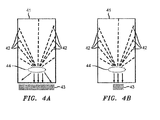
- FIGS 4a and 4b show exemplary schematic representations of a solar radiation collector assembled with a solar cell and a lens.
- solar radiation collector 41 comprises a plurality of internal channels as described with reference to figures 2 and 3 .
- the solar radiation collector is installed on a solar cell 43 (or solar panel).
- a lens 44 is used to further direct the light received by the solar radiation collector 41 and propagated through internal channels 42 toward the solar cell 43.
- the lens 44 is configured to spread (diverge) the received light across a specific larger area of the solar cell; whereas in the particular embodiment of figure 4b , the lens 44 is configured to generate a more compact (convergent) light to be directed to a specific smaller area of the solar cell.
- a solar panel assembly comprising the solar radiation collector, solar cells and one or more lenses.
- angles and dimensions of the internal channels may be designed and optimized based on knowledge of the overall system design requirements.
- the solar radiation collector may be made of any convenient material available in the market such as for example plastic, or in particular printed plastic due to the relatively high reflective capabilities of printed plastics.
- plastic is not the only material that can be used, it is considered one preferred material as it allows for printing complex geometries in a simple and quick way.
- the solution proposed herein therefore provides the possibility of improving the generation of greater energy as solar radiation may be collected over a broad range of incident angles, while keeping the size of the overall device to a minimum as very large solar concentrators are not required
- the proposed solar radiation collector may be designed in any shape or structure thereby providing the possibility of tailoring solutions for any application and any global position of the actual deployment.
- the solar radiation collector is made by printing a body in plastic it will be lightweight, inexpensive and highly flexible in design.
Landscapes
- Photovoltaic Devices (AREA)
Priority Applications (1)
| Application Number | Priority Date | Filing Date | Title |
|---|---|---|---|
| EP13305056.7A EP2757594A1 (de) | 2013-01-18 | 2013-01-18 | Sonnenstrahlungskollektor |
Applications Claiming Priority (1)
| Application Number | Priority Date | Filing Date | Title |
|---|---|---|---|
| EP13305056.7A EP2757594A1 (de) | 2013-01-18 | 2013-01-18 | Sonnenstrahlungskollektor |
Publications (1)
| Publication Number | Publication Date |
|---|---|
| EP2757594A1 true EP2757594A1 (de) | 2014-07-23 |
Family
ID=47715943
Family Applications (1)
| Application Number | Title | Priority Date | Filing Date |
|---|---|---|---|
| EP13305056.7A Withdrawn EP2757594A1 (de) | 2013-01-18 | 2013-01-18 | Sonnenstrahlungskollektor |
Country Status (1)
| Country | Link |
|---|---|
| EP (1) | EP2757594A1 (de) |
Cited By (1)
| Publication number | Priority date | Publication date | Assignee | Title |
|---|---|---|---|---|
| US10295309B2 (en) | 2013-07-08 | 2019-05-21 | Loukus Technologies, Inc. | Core structured components and containers |
Citations (4)
| Publication number | Priority date | Publication date | Assignee | Title |
|---|---|---|---|---|
| US4411490A (en) * | 1980-08-18 | 1983-10-25 | Maurice Daniel | Apparatus for collecting, distributing and utilizing solar radiation |
| US5575860A (en) * | 1994-08-11 | 1996-11-19 | Cherney; Matthew | Fiber optic power-generation system |
| US20020148497A1 (en) * | 2001-03-23 | 2002-10-17 | Makoto Sasaoka | Concentrating photovoltaic module and concentrating photovoltaic power generating system |
| GB2463635A (en) * | 2008-07-23 | 2010-03-24 | Xiaodong Zhang | Combined solar and LED light |
-
2013
- 2013-01-18 EP EP13305056.7A patent/EP2757594A1/de not_active Withdrawn
Patent Citations (4)
| Publication number | Priority date | Publication date | Assignee | Title |
|---|---|---|---|---|
| US4411490A (en) * | 1980-08-18 | 1983-10-25 | Maurice Daniel | Apparatus for collecting, distributing and utilizing solar radiation |
| US5575860A (en) * | 1994-08-11 | 1996-11-19 | Cherney; Matthew | Fiber optic power-generation system |
| US20020148497A1 (en) * | 2001-03-23 | 2002-10-17 | Makoto Sasaoka | Concentrating photovoltaic module and concentrating photovoltaic power generating system |
| GB2463635A (en) * | 2008-07-23 | 2010-03-24 | Xiaodong Zhang | Combined solar and LED light |
Cited By (1)
| Publication number | Priority date | Publication date | Assignee | Title |
|---|---|---|---|---|
| US10295309B2 (en) | 2013-07-08 | 2019-05-21 | Loukus Technologies, Inc. | Core structured components and containers |
Similar Documents
| Publication | Publication Date | Title |
|---|---|---|
| US8119905B2 (en) | Combination non-imaging concentrator | |
| JP4852233B2 (ja) | 管状カバーを備えたレシーバー管及びそれを有するパラボラトラフコレクタ | |
| CN102313975B (zh) | 聚光系统 | |
| CN110998177A (zh) | 利用光纤维的太阳光发电机组及应用太阳光发电机组的发电系统 | |
| CN102272538A (zh) | 光采集和聚集系统 | |
| EP2446306A1 (de) | Genopptes lichtsammel- und konzentrationssystem, komponenten und verfahren | |
| MX2011011370A (es) | Concentrador de luz sin formacion de imagen. | |
| WO2009063416A2 (en) | Thin and efficient collecting optics for solar system | |
| CN109496367B (zh) | 用于捕获入射太阳光并且将其传输到至少一个太阳能电池的光学机械系统和对应的方法 | |
| CN101581502B (zh) | 槽式顺向聚焦轴向传光太阳能聚光器 | |
| KR100933213B1 (ko) | 태양광 발전용 집광 렌즈 | |
| KR102204500B1 (ko) | 자동차용 평면 집광형 태양광 발전장치 | |
| US20170131532A1 (en) | Stamped solar collector concentrator system | |
| EP2757594A1 (de) | Sonnenstrahlungskollektor | |
| CN104769731A (zh) | 用于聚集太阳能的改进装置 | |
| US20200244217A1 (en) | Planar solar concentrator | |
| JP5655146B2 (ja) | 集光型レンズアレイおよびそれを備えた太陽電池 | |
| US8723016B2 (en) | Low profile solar concentrator | |
| WO2012026572A1 (ja) | 集光装置、光発電装置及び光熱変換装置 | |
| EP4585864A1 (de) | Spektralteilungsvorrichtung für ein sonnenkonzentratorsystem | |
| RU2659319C1 (ru) | Неподвижный концентратор солнечного излучения с оптическим способом наведения | |
| WO2014116498A1 (en) | Solar waveguide concentrator | |
| WO2006039156A2 (en) | Method and apparatus for illuminating a solar cell with indirect sunrays | |
| KR101217247B1 (ko) | 집광형 태양전지 | |
| Karp et al. | Radial coupling method for orthogonal concentration within planar micro-optic solar collectors |
Legal Events
| Date | Code | Title | Description |
|---|---|---|---|
| PUAI | Public reference made under article 153(3) epc to a published international application that has entered the european phase |
Free format text: ORIGINAL CODE: 0009012 |
|
| 17P | Request for examination filed |
Effective date: 20130118 |
|
| AK | Designated contracting states |
Kind code of ref document: A1 Designated state(s): AL AT BE BG CH CY CZ DE DK EE ES FI FR GB GR HR HU IE IS IT LI LT LU LV MC MK MT NL NO PL PT RO RS SE SI SK SM TR |
|
| AX | Request for extension of the european patent |
Extension state: BA ME |
|
| RAP1 | Party data changed (applicant data changed or rights of an application transferred) |
Owner name: ALCATEL LUCENT |
|
| R17P | Request for examination filed (corrected) |
Effective date: 20150123 |
|
| RBV | Designated contracting states (corrected) |
Designated state(s): AL AT BE BG CH CY CZ DE DK EE ES FI FR GB GR HR HU IE IS IT LI LT LU LV MC MK MT NL NO PL PT RO RS SE SI SK SM TR |
|
| STAA | Information on the status of an ep patent application or granted ep patent |
Free format text: STATUS: THE APPLICATION IS DEEMED TO BE WITHDRAWN |
|
| 18D | Application deemed to be withdrawn |
Effective date: 20150124 |