EP2758732B1 - Dispositif de refroidissement dans lequel la hauteur des clayettes peut être réglée - Google Patents
Dispositif de refroidissement dans lequel la hauteur des clayettes peut être réglée Download PDFInfo
- Publication number
- EP2758732B1 EP2758732B1 EP12766062.9A EP12766062A EP2758732B1 EP 2758732 B1 EP2758732 B1 EP 2758732B1 EP 12766062 A EP12766062 A EP 12766062A EP 2758732 B1 EP2758732 B1 EP 2758732B1
- Authority
- EP
- European Patent Office
- Prior art keywords
- shelf
- adaptor
- retainer
- pin
- disposed
- Prior art date
- Legal status (The legal status is an assumption and is not a legal conclusion. Google has not performed a legal analysis and makes no representation as to the accuracy of the status listed.)
- Active
Links
Images

Classifications
-
- F—MECHANICAL ENGINEERING; LIGHTING; HEATING; WEAPONS; BLASTING
- F25—REFRIGERATION OR COOLING; COMBINED HEATING AND REFRIGERATION SYSTEMS; HEAT PUMP SYSTEMS; MANUFACTURE OR STORAGE OF ICE; LIQUEFACTION SOLIDIFICATION OF GASES
- F25D—REFRIGERATORS; COLD ROOMS; ICE-BOXES; COOLING OR FREEZING APPARATUS NOT OTHERWISE PROVIDED FOR
- F25D25/00—Charging, supporting, and discharging the articles to be cooled
- F25D25/02—Charging, supporting, and discharging the articles to be cooled by shelves
-
- F—MECHANICAL ENGINEERING; LIGHTING; HEATING; WEAPONS; BLASTING
- F25—REFRIGERATION OR COOLING; COMBINED HEATING AND REFRIGERATION SYSTEMS; HEAT PUMP SYSTEMS; MANUFACTURE OR STORAGE OF ICE; LIQUEFACTION SOLIDIFICATION OF GASES
- F25D—REFRIGERATORS; COLD ROOMS; ICE-BOXES; COOLING OR FREEZING APPARATUS NOT OTHERWISE PROVIDED FOR
- F25D23/00—General constructional features
- F25D23/06—Walls
- F25D23/065—Details
- F25D23/067—Supporting elements
-
- A—HUMAN NECESSITIES
- A47—FURNITURE; DOMESTIC ARTICLES OR APPLIANCES; COFFEE MILLS; SPICE MILLS; SUCTION CLEANERS IN GENERAL
- A47B—TABLES; DESKS; OFFICE FURNITURE; CABINETS; DRAWERS; GENERAL DETAILS OF FURNITURE
- A47B57/00—Cabinets, racks or shelf units, characterised by features for adjusting shelves or partitions
- A47B57/30—Cabinets, racks or shelf units, characterised by features for adjusting shelves or partitions with means for adjusting the height of detachable shelf supports
-
- F—MECHANICAL ENGINEERING; LIGHTING; HEATING; WEAPONS; BLASTING
- F25—REFRIGERATION OR COOLING; COMBINED HEATING AND REFRIGERATION SYSTEMS; HEAT PUMP SYSTEMS; MANUFACTURE OR STORAGE OF ICE; LIQUEFACTION SOLIDIFICATION OF GASES
- F25D—REFRIGERATORS; COLD ROOMS; ICE-BOXES; COOLING OR FREEZING APPARATUS NOT OTHERWISE PROVIDED FOR
- F25D25/00—Charging, supporting, and discharging the articles to be cooled
- F25D25/04—Charging, supporting, and discharging the articles to be cooled by conveyors
Definitions
- the present invention relates to a cooling device according to the preamble of claim 1, wherein the height of the shelf can be changed.
- a cooling device is known from KR 2009 0007269 U .
- the foodstuffs and various containers are placed on the shelves.
- the distance between the two shelves is required to be adjusted, in other words the height of the shelf is required to be changed in the body.
- channels or rails that extend parallel to each other are disposed on the two opposite side walls of the body so that the height of the shelf can be changed.
- the user changes the height of the shelf by taking it out from the channels at one level and placing at another pair of channels at the desired level.
- the user has to first pull the shelf towards the outside of the body and push back towards the body rear wall after placing it in the channel pair at the desired height level.
- the objects on the shelf has to be at least partially taken out and placed on the shelf again after the operation is completed.
- shelf mechanisms are used in cooling devices that allow the height of the shelf to be changed without entirely taking out of the body by means of different channel structures on the side wall.
- the shelf is fastened to the side wall by means of the pins disposed at the sides thereof and the height of the shelf is adjusted with the movement of the pin inside the channel. Since the side wall is a large component, it is costly and hard to process it. Moreover, from time to time it can be troubling to insert the pins at the sides of the shelf into the channels on the side wall. Any damage that may occur on the pin causes the whole shelf to be replaced.
- a cooling device comprising a shelf which can move horizontally or vertically without having to remove from inside the body due to the channel structure on the side walls.
- the pins at the sides of the shelf are seated into the channel and provide the movement of the shelf.
- EP 1 563 762 A1 discloses an easy height adjustment device for refrigerator shelves, wherein there are guides provided at the inner walls of the refrigerator, and wherein in these guides, a shelf coupled to a retainer can be slid.
- the shelf is coupled to the retainer in such a manner as to its height to be adjustable.
- DE 10 2008 016 861 A1 discloses a cooling device wherein different modules might be used to attach a shelf in the inner room thereof. This arrangement allows for positioning a support for items to be cooled at two different vertical positions.
- U1 relates to a device for vertically changing the position of a support in a cooling device where the device includes a rack and pinion mechanismn.
- US 5 913 584 A equally discloses a vertically adjustable refrigerator shelf.
- CN201 903 253 U relates to a liftable rack of a refrigerator as well.
- WO 2005/003660 A1 discloses a movable shelf for a refrigerator door, wherein the shelf comprises an internal panel against which are removably affixed shelves provided with a rear wall.
- the movable shelf comprises a support having a mounting portion disposed between the internal panel and one of the shelves and which are slidingly fitted along the rear wall of that shelf. A lower portion is projecting downwardly from a shelf and carries a tray.
- the support is incorporating an upper portion which is rotatably supporting a knob which is operatedly coupled to the tray and which is displaced between a first position, in which it maintains the tray in the lower position, and a second position, in which it conducts the tray to the elevated position.
- the aim of the present invention is the realization of a cooling device comprising a shelf, the height of which is provided to be changed without being removed from the inside of the body and which can be easily mounted to the body.
- an adaptor disposed on the side wall and providing the shelf to be adjusted and a retainer movably mounted onto the adaptor are provided.
- a shelf support providing the shelf to be supported is disposed on one surface of the retainer, and a pin enabling the shelf to move in the channel located on the adaptor is disposed on the other surface.
- the shelf support is shaped so that the shelf can be slid and inserted therein.
- the cooling device further comprises one protrusion on each of the opposite side walls of the adaptor and one slide for each protrusion that strengthens the connection between the retainer and the adaptor by surrounding the protrusion during the mounting of the retainer to the adaptor.
- the connection between the retainer and the adaptor is strengthened without preventing the retainer from making sliding movement on the adaptor.
- At least one aligning means is disposed below the protrusion and an opening is arranged above the rail, that is formed so that the aligning means can pass therethrough.
- the aligning means and the protrusion face the same direction. While the retainer is being mounted to the adaptor, the aligning means and the opening must be aligned. At this time, the pin is aligned with the channel. At this position, when the retainer is placed onto the adaptor and slightly pushed upwards, the slides are fit over the protrusions and thus the retainer is fastened to the adaptor. Thus, no additional change is required for seating the pin into the channel.
- the cooling device comprises at least two guides arranged on the adaptor and extending parallel to each other and at least two extensions arranged on the shelf, that are seated into the guides to move inside the guides.
- the shelf is provided to move only in the vertical direction and the movement is provided to be more easily controlled.
- the shelf is prevented from rotating and being overturned.
- a heart shaped mechanism is disposed on the adaptor.
- the pin is disposed on a connection member that is mounted onto the retainer so as to rotate around itself. While the pin moves inside the channels that form the heart mechanism, the connection member rotates and provides the shelf to move only in the vertical direction by absorbing the movement in the horizontal direction.
- the connection member is preferably disc-shaped.
- the heart shaped mechanism comprises two channels that form a curved path wherein the pin moves by being connected to each other from two ends, at least two housings that are arranged on the island-shaped wall located at the inner portions of the channels and that are disposed in the almost same vertical direction and at least two guiding members that provide the pin to move in the proper direction during the movement of the pin between the housings.
- three housings are disposed and the height of the shelf can be changed between three positions.
- At least one adaptor is oppositely disposed on each of the side walls and one retainer is disposed on each of the adaptors.
- one retainer is disposed on each of the adaptors.
- two adaptors and two retainers are disposed on each of the side wall.
- the shelf is provided to be easily mounted to/dismounted from the body.
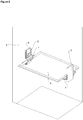
- the cooling device (1) comprises a body (2) having two opposite side walls (3), at least one shelf (4) whereon the items are placed and at least one adaptor (5) that has at least one channel (6), that is detachably mounted onto the side wall (3) and that enables the height of the shelf (4) to be adjusted.
- the shelf (4) is enabled to move inside the body (2) ( Figure 1 , Figure 2 ).
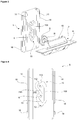
- the cooling device (1) of the present invention furthermore comprises at least one retainer (7) that is mounted onto the adaptor (5) so as to move in the vertical direction and that has a shelf support (8) disposed on the face thereof facing the interior volume of the body (2), wherein one edge of the shelf (4) is placed with a sliding movement ( Figure 2 , Figure 3 , Figure 5 ).
- the adaptor (5) is mounted onto the side wall (3) of the cooling device (1), the retainer (7) onto the adaptor (5) and the shelf (4) onto the shelf support (8) located on the portion of the retainer (7) facing the body (2).
- the shelf (4) Since the components of the mechanism providing the adjustment of the height of the shelf (4) are disposed on the adaptor (5) and the retainer (7), the shelf (4) is in the form of an almost flat plate. Since no movable part is present on the shelf (4) placed to the shelf support (8), the shelf (4) is easily mounted to/dismounted from the body (2).
- the cooling device (1) comprises a pin (9) that is disposed on the face of the retainer (7) facing the side wall (3) and that is placed into the channel (6), thus providing the shelf (4) to move in the vertical direction.
- the pin (9) moves inside the channel (6) located on the adaptor (5) and supports the shelf (4), thus enabling the movement of the shelf (4) in the body (2).
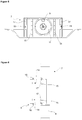
- the cooling device (1) comprises one protrusion (16) disposed on each of the opposite lateral faces of the adaptor (5) and one slide (17) wherein the protrusion (16) is seated, that is disposed on each of the portions of the retainer (7) surrounding the lateral face of the adaptor (5), that provides the retainer (7) to be movably fastened onto the adaptor (5).
- the slide (17) surrounds the protrusion (16), preventing the retainer (7) from being freed from the adaptor (5).
- the retainer (7) is prevented from sliding from and leaving the adaptor (5) since the pin (9) is borne in the channel (6).
- the retainer (7) is provided to be safely mounted onto the adaptor (5) in a manner not limiting the movement of the retainer (7) ( Figure 6 ).
- the cooling device (1) comprises at least one aligning means (18) placed below the protrusion (16) so as to be spaced from the protrusion (16) and an opening (19) that is formed at the portion of the slide (17) coinciding with the aligning means (18) and that enables the retainer (7) to be mounted to the adaptor (5) so that the pin (9) enters into the channel (6) from the lowermost point. While the retainer (7) is being mounted to the adaptor (5), the opening (19) and the aligning means (18) are overlapped, and while the aligning means (18) enters into the opening (19), the portion of the slide (17) remaining above the opening (19) is fit over the protrusion (16) with the retainer (7) being pushed upwards.
- the cooling device (1) comprises at least two guides (14) that extend along the adaptor (5) in the vertical direction and at least two extensions (15) that are disposed on the retainer (7), providing the movement of the shelf (4) to be limited to the vertical direction by moving inside the guides (14).
- the shelf (4) is prevented from moving forwards and backwards, thus from obstructing the movement ( Figure 3, Figure 4 , Figure 5 ).
- the cooling device (1) comprises a heart shaped mechanism (10) that is disposed on the adaptor (5), a connection member (11) that is rotatably placed on the face of the retainer (7) facing the side wall (3) and the pin (9) that is disposed on the connection member (11). While the pin (9) moves inside the channels (6, 106) that form the heart mechanism (10), no movement is required in horizontal direction thanks to the rotation of the connection member (11) wherein the pin (9) is located and the height of the shelf (4) is adjusted only by moving in the vertical direction ( Figure 3, Figure 4 , Figure 5 ).
- the heart shaped mechanism (10) comprises two channels (6, 106) connected to each other from their ends, forming a closed curve wherein the pin (9) moves, at least two housings (12, 112, 212) that are arranged on the channels (6, 106), that are disposed at the almost same vertical direction and at different heights and that provide the shelf (4) to be fixed at the position by the pin (9) being seated therein and at least two guiding members (13, 113) that guide the pin (9) while the pin (9) leaves one housing (12) and passes to the other housing (112).
- the pin (9) leaves the housing (12, 212) wherein it is seated and bears against the guiding member (13, 213), and moves inside the channel (6).
- the pin (9) leaves the guiding member (13, 213) whereon it moves and hits the outer wall of the channel (6), and is seated into the housing (212, 112).
- the pin (9) is seated one by one in each of the housings (112, 212) on the channel (6) wherein it moves.
- the shelf (4) When the height of the shelf (4) is desired to be decreased when the pin (9) is in the uppermost housing (112), the shelf (4) is slightly pushed upwards, thus making the pin (9) hit the guiding member (113) above it and the pin (9) is inserted into the channel (106) which is the continuation of the channel (6) wherein it moves when getting near the uppermost housing (112). The pin (9) continues moving downwards inside the said channel (106) to be seated into the lowermost housing (12), thus providing the height of the shelf (4) to be changed.
- At least one adaptor (5) is oppositely disposed on each of the side walls (3) and one retainer (7) is disposed on each of the adaptors (5).
- two adaptors (5) and two retainers (7) are disposed on each of the side wall (3).
- the shelf (4) is provided to be easily mounted to/dismounted from the body (2).
Landscapes
- Engineering & Computer Science (AREA)
- Chemical & Material Sciences (AREA)
- Combustion & Propulsion (AREA)
- Physics & Mathematics (AREA)
- Mechanical Engineering (AREA)
- Thermal Sciences (AREA)
- General Engineering & Computer Science (AREA)
- Devices That Are Associated With Refrigeration Equipment (AREA)
Claims (4)
- Un dispositif de refroidissement (1) comprenant un corps (2) ayant deux parois latérales opposées (3), au moins une clayette (4) sur laquelle les articles sont placés, au moins un adaptateur (5) qui a au moins un canal (6), qui est monté de manière amovible sur la paroi latérale (3) et qui permet de régler la hauteur de la clayette (4), au moins un dispositif de retenue(7) qui est monté sur un adaptateur correspondant (5) de manière telle que le dispositif de retenue(7) puisse bouger en direction verticale par rapport à l'adaptateur correspondant (5), par une saillie (16) disposée sur chacune des faces latérales opposées de l'adaptateur (5) et une glissière (17) étant prévue dans laquelle la saillie (16) est située, qui est disposée sur chacune des parties du dispositif de retenue (7) entourant la face latérale de l'adaptateur (5) et qui permet au dispositif de retenue (7) d'être fixé de manière mobile sur l'adaptateur (5), et dans lequel le dispositif de retenue (7) comporte un support de tablette (8) disposé sur sa face tournée vers le volume intérieur du corps (2), dans lequel un bord de la clayette (4) est placé avec un mouvement de glissement, et ledit dispositif de refroidissement (1) est caractérisé par une broche (9) qui est disposée sur la face du dispositif de retenue (7) tournée vers la paroi latérale (3) et qui est placée dans le canal (6), permettant ainsi à la clayette (4) de se déplacer dans la direction verticale et est caractérisé en outre par au moins un moyen d'alignement (18) placé sous la saillie (16) de manière à être espacé de la saillie (16) et une ouverture (19) qui est formée à la partie de la glissière (17) qui coïncide avec le moyen d'alignement (18) et qui permet le montage du dispositif de retenue (7) à l'adaptateur (5) afin que la broche (9) entre dans le conduit (6) à partir du point le plus bas.
- Le dispositif de refroidissement (1) selon la déclaration 1, est caractérisé en ce qu'il comporte au moins deux guides (14) qui s'étendent le long de l'adaptateur (5) dans la direction verticale et au moins deux extensions (15) qui sont disposées sur le dispositif de retenue (7), le mouvement de la clayette (4) devant être limité en direction verticale en étant déplacé dans les guides (14).
- Le dispositif de refroidissement (1) selon les déclarations 1 ou 2, est caractérisé en ce qu'il comporte un mécanisme en forme de coeur (10) disposé sur l'adaptateur (5), un élément de liaison (11) qui est placé de manière rotative sur le côté du dispositif de retenue (7) tourné vers la paroi latérale (3) et la broche (9) qui est disposée sur l'élément de liaison (11).
- Le dispositif de refroidissement (1) selon la déclaration 3, est caractérisé en ce que le mécanisme en forme de coeur (10) comprend deux canaux (6, 106) reliés entre eux par leurs extrémités, formant une courbe fermée où la broche (9) se déplace, au moins deux logements (12, 112, 212) qui sont disposés sur les canaux (6, 106), qui sont disposés à peu près dans le même sens vertical et à des hauteurs différentes et qui permettent de fixer la clayette (4) en position par la broche (9) qui y est située et au moins deux guides (13, 113) qui guident la broche (9) pendant que la broche (9) quitte un logement (12) et passe dans l'autre logement (112).
Applications Claiming Priority (2)
| Application Number | Priority Date | Filing Date | Title |
|---|---|---|---|
| TR201109285 | 2011-09-21 | ||
| PCT/EP2012/068671 WO2013041686A2 (fr) | 2011-09-21 | 2012-09-21 | Dispositif de refroidissement dans lequel la hauteur des clayettes peut être réglée |
Publications (3)
| Publication Number | Publication Date |
|---|---|
| EP2758732A2 EP2758732A2 (fr) | 2014-07-30 |
| EP2758732B1 true EP2758732B1 (fr) | 2019-06-12 |
| EP2758732B8 EP2758732B8 (fr) | 2019-07-24 |
Family
ID=46934565
Family Applications (1)
| Application Number | Title | Priority Date | Filing Date |
|---|---|---|---|
| EP12766062.9A Active EP2758732B8 (fr) | 2011-09-21 | 2012-09-21 | Dispositif de refroidissement dans lequel la hauteur des clayettes peut être réglée |
Country Status (2)
| Country | Link |
|---|---|
| EP (1) | EP2758732B8 (fr) |
| WO (1) | WO2013041686A2 (fr) |
Families Citing this family (4)
| Publication number | Priority date | Publication date | Assignee | Title |
|---|---|---|---|---|
| DE102013212384A1 (de) * | 2013-06-27 | 2014-12-31 | BSH Bosch und Siemens Hausgeräte GmbH | Haushaltskältegerät mit einem Frischhaltebehälter und einem Bedienelement und einer Bewegungsführungseinrichtung |
| DE102013212387A1 (de) * | 2013-06-27 | 2014-12-31 | BSH Bosch und Siemens Hausgeräte GmbH | Haushaltskältegerät mit einem Frischhaltebehälter und einem Bedienelement, das als Push-Push-Verriegelungsmechanik zum Bewegen eines Deckels für den Frischhaltebehälter ausgebildet ist |
| CN104006619B (zh) | 2014-05-14 | 2016-09-21 | 海信容声(广东)冰箱有限公司 | 一种冰箱 |
| CN104006598B (zh) * | 2014-05-14 | 2016-04-27 | 海信容声(广东)冰箱有限公司 | 一种冰箱 |
Family Cites Families (10)
| Publication number | Priority date | Publication date | Assignee | Title |
|---|---|---|---|---|
| US3316044A (en) * | 1965-10-14 | 1967-04-25 | Gen Electric | Apparatus for adjusting vertically spaced shelves |
| US5913584A (en) * | 1997-09-23 | 1999-06-22 | White Consolidated Industries, Inc. | Adjustable refrigerator shelf |
| WO2003095912A1 (fr) | 2002-05-10 | 2003-11-20 | Arçelik A.S. | Appareil electromenager |
| BR0302604A (pt) * | 2003-07-03 | 2005-03-29 | Multibras Eletrodomesticos Sa | Prateleira móvel para porta de refrigerador |
| ITTO20040087A1 (it) * | 2004-02-17 | 2004-05-17 | Itw Ind Componemts S R L | Dispositivo per lo spostamento rapido della posizione in altezza di un piano di appoggio interno di un elettrodomestico quale un frigorifero o congelatore |
| DE202007013356U1 (de) * | 2007-05-31 | 2008-10-09 | Liebherr-Hausgeräte Ochsenhausen GmbH | Vorrichtung zur Verstellung eines Bodens oder Abstellers eines Kühl- und/oder Gefriergerätes |
| KR200465945Y1 (ko) * | 2008-01-15 | 2013-03-25 | 삼성전자주식회사 | 냉장고 |
| DE102008016861A1 (de) * | 2008-04-02 | 2009-10-08 | BSH Bosch und Siemens Hausgeräte GmbH | Kältegerät mit entfernbarem Modul |
| IT1403144B1 (it) * | 2010-11-22 | 2013-10-04 | Illinois Tool Works | Dispositivo di supporto regolabile in altezza per un piano di appoggio interno di un elettrodomestico |
| CN201903253U (zh) * | 2010-12-06 | 2011-07-20 | 广东格兰仕集团有限公司 | 冰箱的可升降搁物架 |
-
2012
- 2012-09-21 EP EP12766062.9A patent/EP2758732B8/fr active Active
- 2012-09-21 WO PCT/EP2012/068671 patent/WO2013041686A2/fr not_active Ceased
Also Published As
| Publication number | Publication date |
|---|---|
| WO2013041686A2 (fr) | 2013-03-28 |
| EP2758732B8 (fr) | 2019-07-24 |
| WO2013041686A3 (fr) | 2013-07-18 |
| EP2758732A2 (fr) | 2014-07-30 |
Similar Documents
| Publication | Publication Date | Title |
|---|---|---|
| KR102595327B1 (ko) | 냉장고 | |
| KR102580773B1 (ko) | 냉장고 | |
| US9247810B2 (en) | Device for storing utensils, especially tools | |
| EP2419691B1 (fr) | Etagère coulissante pour réfrigérateurs et congélateurs | |
| US8840205B2 (en) | Refrigerator appliance and a shelf assembly for the same | |
| KR20170140010A (ko) | 냉장고 및 냉장고의 승강 서랍 | |
| EP2758732B1 (fr) | Dispositif de refroidissement dans lequel la hauteur des clayettes peut être réglée | |
| US20130270987A1 (en) | Freezer slide rack alignment | |
| KR101829374B1 (ko) | 냉장고 | |
| CN101208028A (zh) | 用于橱柜的支撑拉出式旋转搁架的改进型框架 | |
| EP2820998B1 (fr) | Ensemble de panier pour un lave-vaisselle | |
| WO2018202364A1 (fr) | Réfrigérateur comprenant un balconnet réglable en hauteur | |
| US10161671B2 (en) | Adjustable shelf for a refrigerator appliance | |
| EP2392240B1 (fr) | Machine à café | |
| US8398187B2 (en) | Refrigerator comprising an extractably guided receptacle for chilled goods | |
| EP2766680B1 (fr) | Dispositif de refroidissement comprenant une clayette dont la hauteur peut être réglée | |
| AU2018410667B2 (en) | Storage structure for refrigerator appliance | |
| EP3167755B1 (fr) | Ensemble de coulisse de tiroir | |
| US8469470B2 (en) | Refrigerator unit and/or a freezer unit | |
| EP3538828B1 (fr) | Réfrigérateur avec étagère de corps réglable en hauteur | |
| EP2405217A2 (fr) | Mécanisme d'étagère à niveau ajustable | |
| EP1853857A1 (fr) | Dispositif de refrigeration | |
| EP2659210B1 (fr) | Dispositif de refroidissement comportant un tiroir | |
| EP4206594B1 (fr) | Réfrigérateur doté d'une etagère de porte à profondeur réglable | |
| US20170059236A1 (en) | Domestic cooling appliance with a shelf to which differently sized food receiving units are attachable |
Legal Events
| Date | Code | Title | Description |
|---|---|---|---|
| PUAI | Public reference made under article 153(3) epc to a published international application that has entered the european phase |
Free format text: ORIGINAL CODE: 0009012 |
|
| 17P | Request for examination filed |
Effective date: 20140319 |
|
| AK | Designated contracting states |
Kind code of ref document: A2 Designated state(s): AL AT BE BG CH CY CZ DE DK EE ES FI FR GB GR HR HU IE IS IT LI LT LU LV MC MK MT NL NO PL PT RO RS SE SI SK SM TR |
|
| DAX | Request for extension of the european patent (deleted) | ||
| RIC1 | Information provided on ipc code assigned before grant |
Ipc: F25D 25/02 20060101ALI20181220BHEP Ipc: A47B 57/30 20060101ALI20181220BHEP Ipc: F25D 23/06 20060101AFI20181220BHEP Ipc: F25D 25/04 20060101ALI20181220BHEP |
|
| GRAP | Despatch of communication of intention to grant a patent |
Free format text: ORIGINAL CODE: EPIDOSNIGR1 |
|
| STAA | Information on the status of an ep patent application or granted ep patent |
Free format text: STATUS: GRANT OF PATENT IS INTENDED |
|
| INTG | Intention to grant announced |
Effective date: 20190304 |
|
| GRAS | Grant fee paid |
Free format text: ORIGINAL CODE: EPIDOSNIGR3 |
|
| GRAA | (expected) grant |
Free format text: ORIGINAL CODE: 0009210 |
|
| STAA | Information on the status of an ep patent application or granted ep patent |
Free format text: STATUS: THE PATENT HAS BEEN GRANTED |
|
| AK | Designated contracting states |
Kind code of ref document: B1 Designated state(s): AL AT BE BG CH CY CZ DE DK EE ES FI FR GB GR HR HU IE IS IT LI LT LU LV MC MK MT NL NO PL PT RO RS SE SI SK SM TR |
|
| REG | Reference to a national code |
Ref country code: GB Ref legal event code: FG4D |
|
| REG | Reference to a national code |
Ref country code: CH Ref legal event code: EP |
|
| REG | Reference to a national code |
Ref country code: AT Ref legal event code: REF Ref document number: 1143093 Country of ref document: AT Kind code of ref document: T Effective date: 20190615 |
|
| REG | Reference to a national code |
Ref country code: CH Ref legal event code: PK Free format text: BERICHTIGUNG B8 |
|
| RAP2 | Party data changed (patent owner data changed or rights of a patent transferred) |
Owner name: ARCELIK ANONIM SIRKETI |
|
| REG | Reference to a national code |
Ref country code: DE Ref legal event code: R096 Ref document number: 602012060943 Country of ref document: DE |
|
| REG | Reference to a national code |
Ref country code: IE Ref legal event code: FG4D |
|
| REG | Reference to a national code |
Ref country code: NL Ref legal event code: MP Effective date: 20190612 |
|
| REG | Reference to a national code |
Ref country code: LT Ref legal event code: MG4D |
|
| PG25 | Lapsed in a contracting state [announced via postgrant information from national office to epo] |
Ref country code: FI Free format text: LAPSE BECAUSE OF FAILURE TO SUBMIT A TRANSLATION OF THE DESCRIPTION OR TO PAY THE FEE WITHIN THE PRESCRIBED TIME-LIMIT Effective date: 20190612 Ref country code: NO Free format text: LAPSE BECAUSE OF FAILURE TO SUBMIT A TRANSLATION OF THE DESCRIPTION OR TO PAY THE FEE WITHIN THE PRESCRIBED TIME-LIMIT Effective date: 20190912 Ref country code: HR Free format text: LAPSE BECAUSE OF FAILURE TO SUBMIT A TRANSLATION OF THE DESCRIPTION OR TO PAY THE FEE WITHIN THE PRESCRIBED TIME-LIMIT Effective date: 20190612 Ref country code: SE Free format text: LAPSE BECAUSE OF FAILURE TO SUBMIT A TRANSLATION OF THE DESCRIPTION OR TO PAY THE FEE WITHIN THE PRESCRIBED TIME-LIMIT Effective date: 20190612 Ref country code: AL Free format text: LAPSE BECAUSE OF FAILURE TO SUBMIT A TRANSLATION OF THE DESCRIPTION OR TO PAY THE FEE WITHIN THE PRESCRIBED TIME-LIMIT Effective date: 20190612 Ref country code: LT Free format text: LAPSE BECAUSE OF FAILURE TO SUBMIT A TRANSLATION OF THE DESCRIPTION OR TO PAY THE FEE WITHIN THE PRESCRIBED TIME-LIMIT Effective date: 20190612 |
|
| PG25 | Lapsed in a contracting state [announced via postgrant information from national office to epo] |
Ref country code: BG Free format text: LAPSE BECAUSE OF FAILURE TO SUBMIT A TRANSLATION OF THE DESCRIPTION OR TO PAY THE FEE WITHIN THE PRESCRIBED TIME-LIMIT Effective date: 20190912 Ref country code: RS Free format text: LAPSE BECAUSE OF FAILURE TO SUBMIT A TRANSLATION OF THE DESCRIPTION OR TO PAY THE FEE WITHIN THE PRESCRIBED TIME-LIMIT Effective date: 20190612 Ref country code: GR Free format text: LAPSE BECAUSE OF FAILURE TO SUBMIT A TRANSLATION OF THE DESCRIPTION OR TO PAY THE FEE WITHIN THE PRESCRIBED TIME-LIMIT Effective date: 20190913 Ref country code: LV Free format text: LAPSE BECAUSE OF FAILURE TO SUBMIT A TRANSLATION OF THE DESCRIPTION OR TO PAY THE FEE WITHIN THE PRESCRIBED TIME-LIMIT Effective date: 20190612 |
|
| REG | Reference to a national code |
Ref country code: AT Ref legal event code: MK05 Ref document number: 1143093 Country of ref document: AT Kind code of ref document: T Effective date: 20190612 |
|
| PG25 | Lapsed in a contracting state [announced via postgrant information from national office to epo] |
Ref country code: SK Free format text: LAPSE BECAUSE OF FAILURE TO SUBMIT A TRANSLATION OF THE DESCRIPTION OR TO PAY THE FEE WITHIN THE PRESCRIBED TIME-LIMIT Effective date: 20190612 Ref country code: RO Free format text: LAPSE BECAUSE OF FAILURE TO SUBMIT A TRANSLATION OF THE DESCRIPTION OR TO PAY THE FEE WITHIN THE PRESCRIBED TIME-LIMIT Effective date: 20190612 Ref country code: EE Free format text: LAPSE BECAUSE OF FAILURE TO SUBMIT A TRANSLATION OF THE DESCRIPTION OR TO PAY THE FEE WITHIN THE PRESCRIBED TIME-LIMIT Effective date: 20190612 Ref country code: AT Free format text: LAPSE BECAUSE OF FAILURE TO SUBMIT A TRANSLATION OF THE DESCRIPTION OR TO PAY THE FEE WITHIN THE PRESCRIBED TIME-LIMIT Effective date: 20190612 Ref country code: NL Free format text: LAPSE BECAUSE OF FAILURE TO SUBMIT A TRANSLATION OF THE DESCRIPTION OR TO PAY THE FEE WITHIN THE PRESCRIBED TIME-LIMIT Effective date: 20190612 Ref country code: CZ Free format text: LAPSE BECAUSE OF FAILURE TO SUBMIT A TRANSLATION OF THE DESCRIPTION OR TO PAY THE FEE WITHIN THE PRESCRIBED TIME-LIMIT Effective date: 20190612 Ref country code: PT Free format text: LAPSE BECAUSE OF FAILURE TO SUBMIT A TRANSLATION OF THE DESCRIPTION OR TO PAY THE FEE WITHIN THE PRESCRIBED TIME-LIMIT Effective date: 20191014 |
|
| PG25 | Lapsed in a contracting state [announced via postgrant information from national office to epo] |
Ref country code: SM Free format text: LAPSE BECAUSE OF FAILURE TO SUBMIT A TRANSLATION OF THE DESCRIPTION OR TO PAY THE FEE WITHIN THE PRESCRIBED TIME-LIMIT Effective date: 20190612 Ref country code: IT Free format text: LAPSE BECAUSE OF FAILURE TO SUBMIT A TRANSLATION OF THE DESCRIPTION OR TO PAY THE FEE WITHIN THE PRESCRIBED TIME-LIMIT Effective date: 20190612 Ref country code: ES Free format text: LAPSE BECAUSE OF FAILURE TO SUBMIT A TRANSLATION OF THE DESCRIPTION OR TO PAY THE FEE WITHIN THE PRESCRIBED TIME-LIMIT Effective date: 20190612 Ref country code: IS Free format text: LAPSE BECAUSE OF FAILURE TO SUBMIT A TRANSLATION OF THE DESCRIPTION OR TO PAY THE FEE WITHIN THE PRESCRIBED TIME-LIMIT Effective date: 20191012 |
|
| REG | Reference to a national code |
Ref country code: DE Ref legal event code: R097 Ref document number: 602012060943 Country of ref document: DE |
|
| PLBE | No opposition filed within time limit |
Free format text: ORIGINAL CODE: 0009261 |
|
| STAA | Information on the status of an ep patent application or granted ep patent |
Free format text: STATUS: NO OPPOSITION FILED WITHIN TIME LIMIT |
|
| PG25 | Lapsed in a contracting state [announced via postgrant information from national office to epo] |
Ref country code: PL Free format text: LAPSE BECAUSE OF FAILURE TO SUBMIT A TRANSLATION OF THE DESCRIPTION OR TO PAY THE FEE WITHIN THE PRESCRIBED TIME-LIMIT Effective date: 20190612 Ref country code: DK Free format text: LAPSE BECAUSE OF FAILURE TO SUBMIT A TRANSLATION OF THE DESCRIPTION OR TO PAY THE FEE WITHIN THE PRESCRIBED TIME-LIMIT Effective date: 20190612 |
|
| 26N | No opposition filed |
Effective date: 20200313 |
|
| PG25 | Lapsed in a contracting state [announced via postgrant information from national office to epo] |
Ref country code: IS Free format text: LAPSE BECAUSE OF FAILURE TO SUBMIT A TRANSLATION OF THE DESCRIPTION OR TO PAY THE FEE WITHIN THE PRESCRIBED TIME-LIMIT Effective date: 20200224 Ref country code: SI Free format text: LAPSE BECAUSE OF FAILURE TO SUBMIT A TRANSLATION OF THE DESCRIPTION OR TO PAY THE FEE WITHIN THE PRESCRIBED TIME-LIMIT Effective date: 20190612 Ref country code: MC Free format text: LAPSE BECAUSE OF FAILURE TO SUBMIT A TRANSLATION OF THE DESCRIPTION OR TO PAY THE FEE WITHIN THE PRESCRIBED TIME-LIMIT Effective date: 20190612 |
|
| REG | Reference to a national code |
Ref country code: CH Ref legal event code: PL |
|
| PG2D | Information on lapse in contracting state deleted |
Ref country code: IS |
|
| PG25 | Lapsed in a contracting state [announced via postgrant information from national office to epo] |
Ref country code: IE Free format text: LAPSE BECAUSE OF NON-PAYMENT OF DUE FEES Effective date: 20190921 Ref country code: LU Free format text: LAPSE BECAUSE OF NON-PAYMENT OF DUE FEES Effective date: 20190921 Ref country code: CH Free format text: LAPSE BECAUSE OF NON-PAYMENT OF DUE FEES Effective date: 20190930 Ref country code: LI Free format text: LAPSE BECAUSE OF NON-PAYMENT OF DUE FEES Effective date: 20190930 |
|
| REG | Reference to a national code |
Ref country code: BE Ref legal event code: MM Effective date: 20190930 |
|
| PG25 | Lapsed in a contracting state [announced via postgrant information from national office to epo] |
Ref country code: BE Free format text: LAPSE BECAUSE OF NON-PAYMENT OF DUE FEES Effective date: 20190930 |
|
| GBPC | Gb: european patent ceased through non-payment of renewal fee |
Effective date: 20190921 |
|
| PG25 | Lapsed in a contracting state [announced via postgrant information from national office to epo] |
Ref country code: GB Free format text: LAPSE BECAUSE OF NON-PAYMENT OF DUE FEES Effective date: 20190921 Ref country code: FR Free format text: LAPSE BECAUSE OF NON-PAYMENT OF DUE FEES Effective date: 20190930 |
|
| PG25 | Lapsed in a contracting state [announced via postgrant information from national office to epo] |
Ref country code: CY Free format text: LAPSE BECAUSE OF FAILURE TO SUBMIT A TRANSLATION OF THE DESCRIPTION OR TO PAY THE FEE WITHIN THE PRESCRIBED TIME-LIMIT Effective date: 20190612 |
|
| PG25 | Lapsed in a contracting state [announced via postgrant information from national office to epo] |
Ref country code: MT Free format text: LAPSE BECAUSE OF FAILURE TO SUBMIT A TRANSLATION OF THE DESCRIPTION OR TO PAY THE FEE WITHIN THE PRESCRIBED TIME-LIMIT Effective date: 20190612 Ref country code: HU Free format text: LAPSE BECAUSE OF FAILURE TO SUBMIT A TRANSLATION OF THE DESCRIPTION OR TO PAY THE FEE WITHIN THE PRESCRIBED TIME-LIMIT; INVALID AB INITIO Effective date: 20120921 |
|
| PG25 | Lapsed in a contracting state [announced via postgrant information from national office to epo] |
Ref country code: MK Free format text: LAPSE BECAUSE OF FAILURE TO SUBMIT A TRANSLATION OF THE DESCRIPTION OR TO PAY THE FEE WITHIN THE PRESCRIBED TIME-LIMIT Effective date: 20190612 |
|
| PGFP | Annual fee paid to national office [announced via postgrant information from national office to epo] |
Ref country code: DE Payment date: 20250919 Year of fee payment: 14 |
|
| PGFP | Annual fee paid to national office [announced via postgrant information from national office to epo] |
Ref country code: TR Payment date: 20250918 Year of fee payment: 14 |