EP2758736B1 - Système de chauffage destiné à chauffer un milieu de traitement gazeux pour un séchoir - Google Patents
Système de chauffage destiné à chauffer un milieu de traitement gazeux pour un séchoir Download PDFInfo
- Publication number
- EP2758736B1 EP2758736B1 EP12746351.1A EP12746351A EP2758736B1 EP 2758736 B1 EP2758736 B1 EP 2758736B1 EP 12746351 A EP12746351 A EP 12746351A EP 2758736 B1 EP2758736 B1 EP 2758736B1
- Authority
- EP
- European Patent Office
- Prior art keywords
- gaseous
- medium
- treatment
- mixing chamber
- treatment medium
- Prior art date
- Legal status (The legal status is an assumption and is not a legal conclusion. Google has not performed a legal analysis and makes no representation as to the accuracy of the status listed.)
- Not-in-force
Links
Images


Classifications
-
- F—MECHANICAL ENGINEERING; LIGHTING; HEATING; WEAPONS; BLASTING
- F26—DRYING
- F26B—DRYING SOLID MATERIALS OR OBJECTS BY REMOVING LIQUID THEREFROM
- F26B13/00—Machines and apparatus for drying fabrics, fibres, yarns, or other materials in long lengths, with progressive movement
- F26B13/10—Arrangements for feeding, heating or supporting materials; Controlling movement, tension or position of materials
- F26B13/14—Rollers, drums, cylinders; Arrangement of drives, supports, bearings, cleaning
- F26B13/16—Rollers, drums, cylinders; Arrangement of drives, supports, bearings, cleaning perforated in combination with hot air blowing or suction devices, e.g. sieve drum dryers
-
- F—MECHANICAL ENGINEERING; LIGHTING; HEATING; WEAPONS; BLASTING
- F26—DRYING
- F26B—DRYING SOLID MATERIALS OR OBJECTS BY REMOVING LIQUID THEREFROM
- F26B21/00—Arrangements for supplying or controlling air or other gases for drying solid materials or objects
- F26B21/001—Air generating units, e.g. movable or independent of drying enclosure
-
- F—MECHANICAL ENGINEERING; LIGHTING; HEATING; WEAPONS; BLASTING
- F26—DRYING
- F26B—DRYING SOLID MATERIALS OR OBJECTS BY REMOVING LIQUID THEREFROM
- F26B21/00—Arrangements for supplying or controlling air or other gases for drying solid materials or objects
- F26B21/20—Circulating air or gases in closed cycles, e.g. wholly within the drying enclosure
- F26B21/25—Circulating air or gases in closed cycles, e.g. wholly within the drying enclosure partly outside the drying enclosure
-
- F—MECHANICAL ENGINEERING; LIGHTING; HEATING; WEAPONS; BLASTING
- F26—DRYING
- F26B—DRYING SOLID MATERIALS OR OBJECTS BY REMOVING LIQUID THEREFROM
- F26B21/00—Arrangements for supplying or controlling air or other gases for drying solid materials or objects
- F26B21/50—Ducting arrangements from the source of air or other gases to the materials or objects being dried
Definitions
- the invention relates to a device, preferably a dryer, with a heating system for heating a gaseous treatment medium for a device, preferably a dryer, for treating a preferably web-shaped Guts with the gaseous treatment medium according to the preamble of claim 1, and a method for heating a gaseous treatment medium for a device for treating a preferably web-shaped product according to claim 3.
- US 5,937,538 discloses a device, in particular a dryer, for treating a preferably bahförmigen Guts with a gaseous treatment medium.
- a heating medium is heated by means of a gas burner and mixed with a gaseous treatment medium which has already been used for treating and is returned from the device.
- the previously known heating systems are mostly used for dryers for drying a preferably web-shaped material.
- the heating systems serve to heat a gaseous treatment medium with which a preferably sheet-like material can be dried within a drying chamber of the dryer.
- Such a heating system often has a gas burner as a heating device.
- the cooled treatment medium returned from the drying chamber is then heated to one of Heating device heated heating medium mixed.
- the mixture is then fed as heated gaseous treatment medium of the drying chamber to dry the web-shaped Guts.
- the vanes may be vane or vane elements.
- the heater may be a gas burner, a thermal oil heater or an electric heater.
- the gaseous heating medium may comprise a mixture of fresh air and combustion exhaust gas of the gas burner. If an electric heater or the thermal oil heater is used, the gaseous heating medium may be the fresh air heated by the electric heater or the thermal oil heater, or it may be a mixture of fresh air and gas warmed by the electric heater or the thermal oil heater.
- An antechamber for mixing the fresh air with the combustion exhaust gases of the gas burner may be provided. If an electric heater or the thermal oil heater is used, an antechamber may be for mixing the fresh air and the gas heated by the electric heater or the thermal oil heater.
- the pre-chamber is preferably arranged inside the mixing chamber. This has the advantage that the waste heat of the prechamber can be used to heat the gases in the mixing chamber.
- the gaseous treatment medium returned by the device preferably the dryer, can be introduced into the mixing chamber in such a way that turbulences occur in the mixing chamber when the recycled treatment medium is introduced into the mixing chamber.
- the turbulences of the recirculated gaseous treatment medium rotate in the opposite direction to the turbulence of the introduced into the mixing chamber gaseous heating medium. This leads in addition to a better mixing of the two gaseous media.
- the mixing chamber preferably has a cylindrical inner space, wherein the recirculated, gaseous treatment medium can be introduced tangentially into the cylindrical mixing chamber, so that turbulences occur in the mixing chamber when the recirculated, gaseous treatment medium is introduced into the mixing chamber.
- the recirculated, gaseous treatment medium When introducing the recirculated, gaseous treatment medium into the mixing chamber, the recirculated, gaseous treatment medium can be deflected via guide elements, so that turbulences occur in the mixing chamber when the recirculated, gaseous treatment medium is introduced into the mixing chamber.
- a flow rectifier In the flow direction behind the mixing chamber, a flow rectifier can be arranged, which rectifies the flow of the heated, gaseous treatment medium.
- the heated gaseous treatment medium is the mixture of gaseous heating medium and recycled, gaseous treatment medium.
- the flow rectifier may be a channel extending in the flow direction, which has Strömungsleitbleche for rectifying the flow of the gaseous treatment medium.
- the flow baffles are aligned in the flow direction within the channel.
- the flow straightener may be a screen or perforated plate arranged in the cross-sectional area of the channel.
- a device for the treatment, in particular for drying, of a preferably web-shaped Guts.
- the web-shaped material is in particular a textile web.
- the device may have a treatment space through which the material to be dried can be guided.
- the gaseous treatment medium in the treatment space flows through the web-like material.
- the device may be a dryer and the web-shaped material can by means of the flow with the gaseous treatment medium be dried.
- the device can also be a thermobonding device and the web-shaped material can be thermobonded by means of the flow with the gaseous treatment medium.
- the device has a heating system for heating the gaseous treatment medium.
- the heating system has a heating device and a mixing chamber, wherein in the mixing chamber, a heated by the heater, gaseous heating medium and a recirculated from the treatment chamber, gaseous treatment medium are miscible.
- the gaseous heating medium can be introduced into the mixing chamber in such a manner that turbulences occur in the mixing chamber when the gaseous heating medium is introduced into the mixing chamber, which generates intensive mixing of the gaseous heating medium with the recirculated, gaseous treatment medium.
- the heating system can be arranged outside the treatment room.
- the gaseous treatment medium is often warmed up within the treatment room.
- the exhaust air is discharged directly from the treatment room and the fresh air is introduced directly into the treatment room.
- the gases having different temperatures must first mix within the treatment space. This often leads to unwanted and poorly predictable flow conditions within the treatment room.
- the present method has the advantage that the entire air treatment takes place externally.
- the heated and treated, gaseous treatment medium is supplied to the treatment room at the desired temperature and does not first mix in the treatment room. This improves the flow conditions within the treatment room.
- the exhaust air can be used to heat the fresh air. This also has the advantage that energy can be saved.
- the fresh air can be supplied to the recycled, gaseous treatment medium before, during or after the heating of the recirculated, gaseous treatment medium.
- the fresh air can be supplied to the recirculated, gaseous treatment medium after a portion of the recirculated gaseous treatment medium has already been removed as exhaust air. This has the advantage that the system has already been deprived of the maximum humidity.
- the fresh air may be heated and the heated fresh air may be used to heat the recycled gaseous treatment medium.
- the fresh air can first be mixed with a combustion exhaust gas of a heater and this mixture can be supplied to the recirculated gaseous treatment medium as a gaseous heating medium and heat it thus.
- the heating of the recirculated, gaseous treatment medium takes place in the heating system.
- the heated and mixed with fresh air, gaseous treatment medium can be blown by means of a fan device into the treatment room be, with the fan means is arranged in the flow direction behind the heating system.
- the external air conditioning has the advantage that the individual modules required for air treatment, such as heating system and recirculation fan can be placed anywhere and can be changed or changed independently of the treatment room.
- the individual modules may e.g. be placed in another room, so that the waste heat does not affect the system. Further, e.g. the circulating air fan are silenced separately.
- An air treatment plant for processing a gaseous treatment medium for a device, preferably a dryer, for treating a preferably web-shaped Guts with a gaseous treatment medium may be arranged externally from the treatment room of the device, wherein the web-shaped material is treated in the treatment room.
- fresh air can be supplied for the treatment of the gaseous treatment medium and the gaseous treatment medium can be heated by means of a heating system.
- the air treatment plant comprises a circulating air fan, through which the gaseous treatment medium can be supplied to the treatment room and the gaseous treatment medium already used for treatment can be returned from the treatment room to the air treatment plant.
- the recirculation fan may be arranged in the flow direction behind the heating system.
- Fig. 1 shows a schematic representation of the control system of the gaseous treatment medium for a device for treating a preferably web-like Guts with a gaseous treatment medium 40.
- the device is a dryer 2. It is a warmed, gaseous treatment medium 40 via a feed channel 6 a treatment room fed.
- the treatment room is a drying chamber 28.
- a preferably web-shaped material 12 dried wherein the gaseous treatment medium flows through the web-shaped material to be dried 12 and it dries it. This will be related to Fig.2 explained in more detail.
- the already used for drying, gaseous treatment medium 30 is discharged from the drying chamber 28 and recycled via a channel 4 to an air treatment device 3.
- the gaseous treatment medium 30 already used for drying is colder than the heated, gaseous treatment medium 40 and has a higher humidity than the heated, gaseous treatment medium 40 in that it has absorbed the moisture of the web-like product 12.
- a portion of the recirculated gaseous treatment medium 30 is discharged.
- the remaining part of the recirculated, gaseous treatment medium 30 is mixed with fresh air and heated and fed as heated, gaseous treatment medium 40 via the feed channel 6 of the drying chamber 28.
- the recirculated, gaseous treatment medium is always the gaseous treatment medium 30 which has already been recycled from the treatment chamber or the drying chamber 28 and is already used for treating or for drying, which is returned to the air treatment device 3.
- the gaseous treatment medium or the heated, gaseous treatment medium is the gaseous treatment medium 40, which has already been prepared and is supplied to the treatment chamber or drying chamber 28 for treatment or drying.
- FIG. 2 the drying chamber 28 is shown schematically.
- the heated gaseous treatment medium 40 is introduced into the drying chamber 28.
- a gas-permeable drum 20 is arranged in the drying chamber 28.
- the gas-permeable drum 20 has a gas-permeable drum casing 18.
- a preferably web-shaped material 12 is introduced via a deflection roller 14.
- This web-shaped material 12 is transported by means of the drum 20 in the direction of rotation of the drum 20 arranged on the drum shell 18. A portion of the drum shell 18 is thus always covered by a portion of the web-shaped Guts 12.
- Fig. 3 shows an air treatment device 3, wherein the air treatment device 3 is merely a collection of lines and individual modules, which are explained in more detail below.
- the recycled, gaseous treatment medium 30 is partially removed as exhaust air 32.
- This exhaust air 32 is supplied to a heat exchanger 36 before discharging. Further, fresh air 8 is supplied to the heat exchanger 36 and heated by the heat of the exhaust air 32.
- the remainder of the gaseous, recirculated treatment medium 30 is introduced into a heating system 38.
- the fresh air 8 'warmed up by the heat exchanger 36 is supplied to the heating system 38.
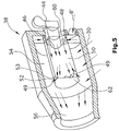
- the heating system 38 is related to the FIGS. 4 and 5 explained in more detail. From the heating system 38 exits the warmed, gaseous treatment medium 40 and is fed via a fan means 42 again via the feed channel 6 of the drying chamber 28.
- the heating system 38 is shown in more detail.
- the gaseous recycled treatment medium 30 is fed via an opening 31 to a mixing chamber 54.
- a gaseous heating medium 49 heated by means of a heating device is introduced into the mixing chamber, the gaseous heating medium 49 being able to be introduced into the mixing chamber 54 such that turbulences occur in the mixing chamber 54 when the gaseous heating medium 49 is introduced into the mixing chamber 54.
- intensive mixing of the gaseous heating medium 49 with the recirculated, gaseous treatment medium 30 takes place.
- the heater is in the present embodiment, a gas burner 44th
- the gaseous heating medium 49 becomes, as in FIG. 5 represented, deflected via guide elements 53 when introduced into the mixing chamber 54 such that upon introduction of the gaseous heating medium 49 in the mixing chamber 54th Turbulence in the mixing chamber 54 occur.
- the guide elements 53 are preferably wing or blade elements.
- the gaseous heating medium 49 was heated by means of the gas burner 44. This is done by mixing combustion gases 46 of the gas burner 44 with the already preheated fresh air 8 '.
- the mixture of combustion exhaust gas 46 and fresh air 8 ' is the heated gaseous heating medium 49.
- the mixing of combustion exhaust gas 46 and fresh air 8' takes place in a prechamber 50.
- the fresh air 8 ' is conveyed via an opening 48 along the circumference of the prechamber 50 on an end face 60 the pre-chamber 50 initiated.
- the opening 52 is arranged through which the heated, gaseous heating medium 49 enters the mixing chamber 54.
- the hot combustion exhaust gas 46 is introduced axially and centrally into the cylindrical prechamber 50. This has the advantage that the hot combustion exhaust gas 46 is surrounded when fresh air 8 'is introduced. Thus, no heat is lost as waste heat.
- the pre-chamber 50 is disposed within the mixing chamber 54, so that the waste heat of the pre-chamber 50 can be used to heat the gaseous media in the mixing chamber 54 and no heat is lost.
- the illustrated mixing chamber 54 has a cylindrical interior.
- the gaseous treatment medium 30 is introduced tangentially into the cylindrical mixing chamber 54.
- turbulences occur in the mixing chamber 54 when the gaseous treatment medium 30 is introduced into the mixing chamber 54.
- the gaseous recirculated treatment medium 30 is preferably introduced in such a way that the turbulences rotate in the opposite direction than the turbulences of the gaseous heating medium 49 introduced into the mixing chamber 54.
- the recycled gaseous treatment medium 30 and the gaseous heating medium 49 mix very well .
- the gaseous, recirculated treatment medium 30 may also be provided guide elements, which lead to a turbulence during insertion of the gaseous treatment medium 30.
- the gaseous heating medium 49 is also introduced tangentially into the cylindrical mixing chamber 54.
- the turbulences of the recirculated, gaseous treatment medium 30 and the turbulence of the gaseous heating medium 49 should always rotate in different directions, so that there is a more intensive mixing of the two gaseous media.
- the fresh air 8 ' can be introduced into the prechamber in such a way that swirling occurs during the introduction of the fresh air 8' into the prechamber.
- the combustion exhaust gases 46 can also be introduced into the prechamber in such a way that turbulences occur when the combustion exhaust gas 46 is introduced into the prechamber 50.
- the turbulences of the fresh air 8 'and the combustion exhaust gas 46 can rotate in different directions. This would also lead to better mixing.
- a tapered channel 56 is arranged in the flow direction behind the mixing chamber 54.
- the tapered channel 56 By the tapered channel 56, the flow rate of the gaseous treatment medium 40 is increased.
- the heated, gaseous treatment medium 40 can exit from the opening 48 and be supplied to the drying chamber 28 via the feed channel 6.
- a flow rectifier may be arranged in the flow direction behind the mixing chamber 54.
- This can be a channel with in Channel direction aligned flow baffles be.
- sieves or perforated plates arranged in the cross-sectional area of a channel can also be used.
Landscapes
- Engineering & Computer Science (AREA)
- Mechanical Engineering (AREA)
- General Engineering & Computer Science (AREA)
- Textile Engineering (AREA)
- Drying Of Solid Materials (AREA)
- Treatment Of Fiber Materials (AREA)
Claims (9)
- Dispositif, de préférence séchoir, servant à traiter un article (12) de préférence en forme de bande avec un milieu de traitement (40) sous forme gazeuse, avec- une chambre de traitement (28), à travers laquelle l'article (12) à traiter peut être guidé, dans lequel un milieu de traitement (40) sous forme gazeuse se trouvant dans la chambre traitement (28) traverse l'article (12),- un système de chauffage (38) servant à réchauffer le milieu de traitement (30, 40) sous forme gazeuse, dans lequel le système de chauffage (38) présente un élément de chauffage et une chambre de mélange (54), dans lequel- un milieu de chauffage (49) sous forme gazeuse pouvant être réchauffé au moyen de l'élément de chauffage et un milieu de traitement (30) sous forme gazeuse ramené depuis la chambre de traitement (28) peuvent être mélangés dans la chambre de mélange (54),dans lequel le milieu de chauffage (49) sous forme gazeuse peut être introduit de telle manière dans la chambre de mélange (54) que des turbulences apparaissent dans la chambre de mélange (54) lors de l'introduction du milieu de chauffage (49) sous forme gazeuse dans la chambre de mélange (54), lesquelles produisent un mélange intense du milieu de chauffage (49) sous forme gazeuse avec le milieu de traitement (30) sous forme gazeuse ramené, dans lequel lors de l'introduction du milieu de chauffage (49) sous forme gazeuse dans la chambre de mélange (54), le milieu de chauffage (49) sous forme gazeuse peut être dévié par l'intermédiaire d'éléments conducteurs (53) de sorte que lors de l'introduction du milieu de chauffage (49) sous forme gazeuse dans la chambre de mélange (54), des turbulences apparaissent dans la chambre de mélange (54),
caractérisé en ce que le milieu de traitement (30) sous forme gazeuse ramené depuis la chambre de traitement peut être introduit par l'intermédiaire d'éléments conducteurs de telle manière dans la chambre de mélange (54) que lors de l'introduction du milieu de traitement (30) ramené dans la chambre de mélange (54), des turbulences apparaissent dans la chambre de mélange (54), lesquelles tournent dans une direction opposée à celle des turbulences du milieu de chauffage (49) sous forme gazeuse introduit dans la chambre de mélange (54). - Dispositif selon la revendication 1, caractérisé en ce que le système de chauffage (38) est disposé à l'extérieur de la chambre de traitement (28).
- Procédé servant à réchauffer un milieu de traitement (30, 40) sous forme gazeuse pour un dispositif, de préférence un séchoir, servant à traiter un article (12) de préférence en forme de bande avec un milieu de traitement (40) sous forme gazeuse, en- ramenant un milieu de traitement (30) sous forme gazeuse déjà utilisé pour le traitement de l'article (12),- introduisant le milieu de traitement (30) sous forme gazeuse ramené dans une chambre de mélange (54),- introduire un milieu de chauffage (49) sous forme gazeuse réchauffé dans la chambre de mélange (54) afin de réchauffer le milieu de traitement (30) sous forme gazeuse ramené, dans lequel le milieu de chauffage (49) sous forme gazeuse est dévié par l'intermédiaire d'éléments conducteurs lors de l'introduction dans la chambre de mélange (54) de sorte que des turbulences apparaissent lors de l'introduction, qui produisent un mélange intense du milieu de chauffage (49) sous forme gazeuse et du milieu de traitement (30) sous forme gazeuse ramené,- dans lequel le milieu de traitement (30) sous forme gazeuse ramené depuis la chambre de traitement est introduit par l'intermédiaire des éléments conducteurs de telle manière dans la chambre de mélange (54) que lors de l'introduction du milieu de traitement (30) ramené dans la chambre de mélange (54), des turbulences apparaissent dans la chambre de mélange (54), qui tournent dans la direction opposée à celle des turbulences du milieu de chauffage (49) sous forme gazeuse introduit dans la chambre de mélange (54).
- Procédé selon la revendication 3, caractérisé par les étapes consistant à- introduire un milieu de traitement (40) sous forme gazeuse réchauffé dans une chambre de traitement (28), dans laquelle un tambour avec une enveloppe de tambour (18) perméable aux gaz est disposé, sur laquelle l'article (12) en forme de bande à traiter peut être placé, dans lequel le milieu de traitement (40) sous forme gazeuse s'écoule en passant par l'article (12) en forme de bande et par l'enveloppe de tambour (18) perméable aux gaz dans l'espace intérieur du tambour,- évacuer le milieu de traitement (30) sous forme gazeuse déjà utilisé pour le traitement sous la forme d'un milieu de traitement (30) sous forme gazeuse ramené hors de l'espace intérieur du tambour et hors de la chambre de traitement (28) aux fins de la préparation externe,- préparer le milieu de traitement (30) sous forme gazeuse ramené, dans lequel le milieu de traitement (30) sous forme gazeuse ramené est préparé en ce qu'il est mélangé à de l'air frais (8, 8') et en ce qu'il est chauffé, et- amener le milieu de traitement (40) sous forme gazeuse préparé à la chambre de traitement (28).
- Procédé selon la revendication 4, caractérisé en ce qu'avant que le milieu de traitement (30) sous forme gazeuse ramené ne soit réchauffé, une partie du milieu de traitement (30) sous forme gazeuse ramené est évacuée sous la forme d'air vicié (32).
- Procédé selon la revendication 5, caractérisé en ce que l'air vicié (32) est utilisé afin de réchauffer l'air frais (8, 8').
- Procédé selon l'une quelconque des revendications 4 à 6, caractérisé en ce que l'air frais (8, 8') est mélangé dans un premier temps avec un gaz d'échappement de combustion (46) d'un dispositif de chauffage, et en ce que ce mélange est amené en tant que milieu de chauffage (49) sous forme gazeuse au milieu de traitement (30) sous forme gazeuse ramené et est chauffé avec ce dernier.
- Procédé selon l'une quelconque des revendications 4 à 7, caractérisé en ce que le réchauffement du milieu de traitement (30) sous forme gazeuse ramené est effectué dans le système de chauffage (38).
- Procédé selon la revendication 8, caractérisé en ce que le milieu de traitement (40) sous forme gazeuse réchauffé et mélangé à de l'air frais (8, 8') est soufflé dans la chambre de traitement (28) à l'aide d'un système de ventilateur (42), dans lequel le système de ventilateur (42) est disposé dans la direction d'écoulement derrière le système de chauffage (38).
Priority Applications (1)
| Application Number | Priority Date | Filing Date | Title |
|---|---|---|---|
| EP16203016.7A EP3168559B1 (fr) | 2011-09-21 | 2012-08-14 | Système de chauffage pour réchauffer un agent de traitement gazeux pour un séchoir |
Applications Claiming Priority (2)
| Application Number | Priority Date | Filing Date | Title |
|---|---|---|---|
| DE102011113837A DE102011113837A1 (de) | 2011-09-21 | 2011-09-21 | Heizsystem zum Erwärmen eines gasförmigen Behandlungsmediums für einen Trockner |
| PCT/EP2012/065887 WO2013041306A1 (fr) | 2011-09-21 | 2012-08-14 | Système de chauffage destiné à chauffer un milieu de traitement gazeux pour un séchoir |
Related Child Applications (2)
| Application Number | Title | Priority Date | Filing Date |
|---|---|---|---|
| EP16203016.7A Division EP3168559B1 (fr) | 2011-09-21 | 2012-08-14 | Système de chauffage pour réchauffer un agent de traitement gazeux pour un séchoir |
| EP16203016.7A Division-Into EP3168559B1 (fr) | 2011-09-21 | 2012-08-14 | Système de chauffage pour réchauffer un agent de traitement gazeux pour un séchoir |
Publications (2)
| Publication Number | Publication Date |
|---|---|
| EP2758736A1 EP2758736A1 (fr) | 2014-07-30 |
| EP2758736B1 true EP2758736B1 (fr) | 2017-04-05 |
Family
ID=46651525
Family Applications (2)
| Application Number | Title | Priority Date | Filing Date |
|---|---|---|---|
| EP16203016.7A Active EP3168559B1 (fr) | 2011-09-21 | 2012-08-14 | Système de chauffage pour réchauffer un agent de traitement gazeux pour un séchoir |
| EP12746351.1A Not-in-force EP2758736B1 (fr) | 2011-09-21 | 2012-08-14 | Système de chauffage destiné à chauffer un milieu de traitement gazeux pour un séchoir |
Family Applications Before (1)
| Application Number | Title | Priority Date | Filing Date |
|---|---|---|---|
| EP16203016.7A Active EP3168559B1 (fr) | 2011-09-21 | 2012-08-14 | Système de chauffage pour réchauffer un agent de traitement gazeux pour un séchoir |
Country Status (5)
| Country | Link |
|---|---|
| US (1) | US10539369B2 (fr) |
| EP (2) | EP3168559B1 (fr) |
| CN (1) | CN103814267B (fr) |
| DE (1) | DE102011113837A1 (fr) |
| WO (1) | WO2013041306A1 (fr) |
Families Citing this family (8)
| Publication number | Priority date | Publication date | Assignee | Title |
|---|---|---|---|---|
| DE102016109413A1 (de) * | 2016-05-23 | 2017-11-23 | Trützschler GmbH + Co KG Textilmaschinenfabrik | Trockner für eine textile Warenbahn mit einer verbesserten Heißluftzufuhr |
| CN107741147A (zh) * | 2017-10-25 | 2018-02-27 | 阜南县大自然工艺品有限公司 | 一种柳编用烘干机 |
| US10712090B2 (en) * | 2018-05-01 | 2020-07-14 | Valmet, Inc. | Through air drying systems and methods with hot air injection |
| CN110296592A (zh) * | 2019-06-25 | 2019-10-01 | 浙江海洋大学 | 一种悬挂式升流海带干燥设备 |
| CN111486672A (zh) * | 2020-06-02 | 2020-08-04 | 古田县尚融生物科技有限公司 | 一种智能自动化节能(汽电)双用烘干设备 |
| DE102021102262A1 (de) * | 2021-02-01 | 2022-08-04 | Trützschler GmbH & Co Kommanditgesellschaft | Vorwärmkammer zum Vorwärmen einer textilen Warenbahn mittels Luft, Trockenanordnung sowie Verwendung einer solchen in einer Maschine zur Herstellung oder Bearbeitung einer textilen Warenbahn |
| CN115682422A (zh) * | 2021-07-22 | 2023-02-03 | 维美德公司 | 紧凑的高性能穿透式热风设备 |
| CN116200836B (zh) * | 2023-02-15 | 2024-12-13 | 德州深顺塑料有限公司 | 一种导热油循环塑料拉丝机弧形烘箱装置 |
Citations (1)
| Publication number | Priority date | Publication date | Assignee | Title |
|---|---|---|---|---|
| DE3932837A1 (de) * | 1989-09-30 | 1991-04-18 | Fleissner Maschf Ag | Luftmischer |
Family Cites Families (19)
| Publication number | Priority date | Publication date | Assignee | Title |
|---|---|---|---|---|
| DE6610711U (de) * | 1975-10-16 | Montforts A | Sieb- bzw. Lochtrommelmaschine | |
| US2032135A (en) * | 1932-02-13 | 1936-02-25 | Harry S Lee | Process and apparatus for burning fuel |
| DE1542352C3 (de) * | 1965-08-28 | 1980-04-03 | Dr. C. Otto & Co Gmbh, 4630 Bochum | Misch- und Reaktionskammer, die nach dem Prinzip der hochturbulenten Drallvermischung gasförmiger, flüssiger oder feinkörniger fester Stoffe mit einem Trägergas arbeitet |
| US3869808A (en) * | 1974-07-05 | 1975-03-11 | Gorham Int Inc | Apparatus for mixing air and steam for delivery to a dryer |
| DE2501268A1 (de) * | 1975-01-15 | 1976-07-22 | Otto Dipl Ing Brust | Integrierte thermische nachverbrennungs- und heizanlage fuer trockenoefen |
| US4116620A (en) * | 1977-05-23 | 1978-09-26 | Tec Systems, Inc. | Web drying apparatus having means for heating recirculated air |
| US4291669A (en) * | 1979-06-25 | 1981-09-29 | Herne Jr Robert H | Efficient fuel burning stove or furnace with thermal energy slow propagation flue structure |
| DE3832632C2 (de) * | 1988-09-26 | 1996-11-21 | Fleissner Maschf Gmbh Co | Siebtrommelvorrichtung zur Wärmebehandlung von bahnförmigem Textilgut |
| DE4016921C2 (de) * | 1989-07-07 | 1994-04-07 | Voith Gmbh J M | Vorrichtung zum Trocknen einer Materialbahn |
| AT396696B (de) | 1992-02-13 | 1993-11-25 | Andritz Patentverwaltung | Verfahren und vorrichtung zum be- und entlüften einer mindestens eine trockengruppe umfassenden trockenpartie einer papiermaschine |
| IL110797A (en) * | 1993-09-15 | 1997-09-30 | Electric Power Res Inst | Fluid atomizer |
| HUP9901098A3 (en) * | 1995-06-07 | 1999-11-29 | Procter & Gamble | Multiple zone limiting orifice drying of cellulosic fibrous structures, apparatus therefor, and cellulosic fibrous structures produced thereby |
| US5937538A (en) | 1996-05-21 | 1999-08-17 | Fort James Corporation | Through air dryer apparatus for drying webs |
| JP3725299B2 (ja) | 1997-06-19 | 2005-12-07 | 株式会社パウダリングジャパン | 通常燃焼及びパルス燃焼両用燃焼器 |
| DE19918102A1 (de) * | 1998-07-09 | 2000-01-27 | Krantz Textiltechnik Gmbh | Verfahren und Vorrichtung zum Behandeln von Gütern mittels eines erwärmten Gases |
| SE524779C2 (sv) * | 2002-12-20 | 2004-10-05 | Andritz Fiber Drying Ab | Anordning vid torkning eller värmebehandling av ett banformigt material |
| US8176650B2 (en) * | 2005-12-13 | 2012-05-15 | Kimberly-Clark Worldwide, Inc. | Method for warming up or cooling down a through-air dryer |
| US9039407B2 (en) * | 2006-11-17 | 2015-05-26 | James K. McKnight | Powdered fuel conversion systems and methods |
| US9861934B2 (en) * | 2014-06-04 | 2018-01-09 | Peerless Mfg.Co | Cyclonic injector and method for reagent gasification and decomposition in a hot gas stream |
-
2011
- 2011-09-21 DE DE102011113837A patent/DE102011113837A1/de not_active Withdrawn
-
2012
- 2012-08-14 WO PCT/EP2012/065887 patent/WO2013041306A1/fr not_active Ceased
- 2012-08-14 EP EP16203016.7A patent/EP3168559B1/fr active Active
- 2012-08-14 CN CN201280045913.4A patent/CN103814267B/zh not_active Expired - Fee Related
- 2012-08-14 EP EP12746351.1A patent/EP2758736B1/fr not_active Not-in-force
- 2012-08-14 US US14/346,117 patent/US10539369B2/en active Active
Patent Citations (1)
| Publication number | Priority date | Publication date | Assignee | Title |
|---|---|---|---|---|
| DE3932837A1 (de) * | 1989-09-30 | 1991-04-18 | Fleissner Maschf Ag | Luftmischer |
Also Published As
| Publication number | Publication date |
|---|---|
| WO2013041306A1 (fr) | 2013-03-28 |
| EP3168559B1 (fr) | 2020-04-01 |
| US10539369B2 (en) | 2020-01-21 |
| US20140223765A1 (en) | 2014-08-14 |
| EP3168559A1 (fr) | 2017-05-17 |
| CN103814267A (zh) | 2014-05-21 |
| DE102011113837A1 (de) | 2013-03-21 |
| EP2758736A1 (fr) | 2014-07-30 |
| CN103814267B (zh) | 2016-04-13 |
Similar Documents
| Publication | Publication Date | Title |
|---|---|---|
| EP2758736B1 (fr) | Système de chauffage destiné à chauffer un milieu de traitement gazeux pour un séchoir | |
| EP3258201B1 (fr) | Dispositif de traitement d'un produit, en particulier destiné à sécher un produit de préférence sous forme de bande | |
| EP2775241B1 (fr) | Dispositif de séchage d'une pièce et procédé de fonctionnement d'un tel dispositif | |
| DE3851636T2 (de) | Verfahren und vorrichtung zum trocknen mit effizientem wirkungsgrad. | |
| DE102011119436B4 (de) | Vorrichtung zum Temperieren von Gegenständen | |
| EP3249326A1 (fr) | Dispositif de séchoir et séchoir pour une bande textile comprenant un dispositif amélioré destiné à apporter de la chaleur | |
| DE102017129017A1 (de) | Verfahren zum Trocknen eines Substrats, Trocknermodul zur Durchführung des Verfahrens sowie Trocknersystem | |
| EP3249327B1 (fr) | Séchoir pour une bande textile comprenant une alimentation en air chaud améliorée | |
| EP2225044B2 (fr) | Dispositif de refroidissement et procédé de refroidissement d'objets sortant d'un dispositif d'application de revêtement | |
| WO2017071862A1 (fr) | Dispositif et procédé de traitement thermique d'une bande de matière textile | |
| EP2735830B1 (fr) | Dispositif et procédé de traitement d'un produit de préférence en forme de bande à l'aide d'un moyen de traitement gazeux | |
| DE102021102262A1 (de) | Vorwärmkammer zum Vorwärmen einer textilen Warenbahn mittels Luft, Trockenanordnung sowie Verwendung einer solchen in einer Maschine zur Herstellung oder Bearbeitung einer textilen Warenbahn | |
| EP1819451B1 (fr) | Procede et installation pour enduire une bande metallique d'un revetement contenant un solvant et pour secher et/ou reticuler ce revetement | |
| EP3084329B1 (fr) | Dispositif et procédé de consolidation thermique d'une bande continue de textile | |
| DE102024131491A1 (de) | Trockner für eine textile Warenbahn | |
| EP2589909A2 (fr) | Dispositif de chauffage ou de séchage de matériaux allongés | |
| DE102016101368B4 (de) | Verfahren und Vorrichtung zum Abkühlen eines Werkstücks im Anschluss an eine Wärmebehandlung | |
| DE3702543A1 (de) | Verfahren und vorrichtung zur behandlung eines faserkabels | |
| EP1446236A2 (fr) | Procede et dispositif de sechage et/ou reticulation d'un revetement d'une bande metallique contenant un solvant | |
| DE3148321A1 (de) | "vorrichtung zum waermebehandeln von horizontal gefuehrten, bahnfoermigen guetern." | |
| DE102023134849A1 (de) | Heizungs-, Belüftungs- und/oder Klimaanlage | |
| DE102021124768A1 (de) | Prozessluftaggregat zum erhitzen einer prozessluft | |
| DE19918102A1 (de) | Verfahren und Vorrichtung zum Behandeln von Gütern mittels eines erwärmten Gases | |
| DE3631480A1 (de) | Verfahren und vorrichtung zum trocknen von trockengut in trocknungsanlagen | |
| DE2823143A1 (de) | Vorrichtung zur waermebehandlung von bahnfoermigem, vorzugsweise luftdurchlaessigem gut |
Legal Events
| Date | Code | Title | Description |
|---|---|---|---|
| PUAI | Public reference made under article 153(3) epc to a published international application that has entered the european phase |
Free format text: ORIGINAL CODE: 0009012 |
|
| 17P | Request for examination filed |
Effective date: 20140320 |
|
| AK | Designated contracting states |
Kind code of ref document: A1 Designated state(s): AL AT BE BG CH CY CZ DE DK EE ES FI FR GB GR HR HU IE IS IT LI LT LU LV MC MK MT NL NO PL PT RO RS SE SI SK SM TR |
|
| DAX | Request for extension of the european patent (deleted) | ||
| 17Q | First examination report despatched |
Effective date: 20150610 |
|
| GRAP | Despatch of communication of intention to grant a patent |
Free format text: ORIGINAL CODE: EPIDOSNIGR1 |
|
| STAA | Information on the status of an ep patent application or granted ep patent |
Free format text: STATUS: GRANT OF PATENT IS INTENDED |
|
| INTG | Intention to grant announced |
Effective date: 20161103 |
|
| GRAS | Grant fee paid |
Free format text: ORIGINAL CODE: EPIDOSNIGR3 |
|
| GRAA | (expected) grant |
Free format text: ORIGINAL CODE: 0009210 |
|
| STAA | Information on the status of an ep patent application or granted ep patent |
Free format text: STATUS: THE PATENT HAS BEEN GRANTED |
|
| AK | Designated contracting states |
Kind code of ref document: B1 Designated state(s): AL AT BE BG CH CY CZ DE DK EE ES FI FR GB GR HR HU IE IS IT LI LT LU LV MC MK MT NL NO PL PT RO RS SE SI SK SM TR |
|
| REG | Reference to a national code |
Ref country code: GB Ref legal event code: FG4D Free format text: NOT ENGLISH |
|
| REG | Reference to a national code |
Ref country code: CH Ref legal event code: EP |
|
| REG | Reference to a national code |
Ref country code: AT Ref legal event code: REF Ref document number: 882217 Country of ref document: AT Kind code of ref document: T Effective date: 20170415 |
|
| REG | Reference to a national code |
Ref country code: IE Ref legal event code: FG4D Free format text: LANGUAGE OF EP DOCUMENT: GERMAN |
|
| REG | Reference to a national code |
Ref country code: DE Ref legal event code: R096 Ref document number: 502012009989 Country of ref document: DE |
|
| REG | Reference to a national code |
Ref country code: NL Ref legal event code: MP Effective date: 20170405 |
|
| REG | Reference to a national code |
Ref country code: FR Ref legal event code: PLFP Year of fee payment: 6 |
|
| REG | Reference to a national code |
Ref country code: LT Ref legal event code: MG4D |
|
| PG25 | Lapsed in a contracting state [announced via postgrant information from national office to epo] |
Ref country code: NL Free format text: LAPSE BECAUSE OF FAILURE TO SUBMIT A TRANSLATION OF THE DESCRIPTION OR TO PAY THE FEE WITHIN THE PRESCRIBED TIME-LIMIT Effective date: 20170405 |
|
| PG25 | Lapsed in a contracting state [announced via postgrant information from national office to epo] |
Ref country code: LT Free format text: LAPSE BECAUSE OF FAILURE TO SUBMIT A TRANSLATION OF THE DESCRIPTION OR TO PAY THE FEE WITHIN THE PRESCRIBED TIME-LIMIT Effective date: 20170405 Ref country code: FI Free format text: LAPSE BECAUSE OF FAILURE TO SUBMIT A TRANSLATION OF THE DESCRIPTION OR TO PAY THE FEE WITHIN THE PRESCRIBED TIME-LIMIT Effective date: 20170405 Ref country code: GR Free format text: LAPSE BECAUSE OF FAILURE TO SUBMIT A TRANSLATION OF THE DESCRIPTION OR TO PAY THE FEE WITHIN THE PRESCRIBED TIME-LIMIT Effective date: 20170706 Ref country code: HR Free format text: LAPSE BECAUSE OF FAILURE TO SUBMIT A TRANSLATION OF THE DESCRIPTION OR TO PAY THE FEE WITHIN THE PRESCRIBED TIME-LIMIT Effective date: 20170405 Ref country code: NO Free format text: LAPSE BECAUSE OF FAILURE TO SUBMIT A TRANSLATION OF THE DESCRIPTION OR TO PAY THE FEE WITHIN THE PRESCRIBED TIME-LIMIT Effective date: 20170705 Ref country code: ES Free format text: LAPSE BECAUSE OF FAILURE TO SUBMIT A TRANSLATION OF THE DESCRIPTION OR TO PAY THE FEE WITHIN THE PRESCRIBED TIME-LIMIT Effective date: 20170405 |
|
| PG25 | Lapsed in a contracting state [announced via postgrant information from national office to epo] |
Ref country code: BG Free format text: LAPSE BECAUSE OF FAILURE TO SUBMIT A TRANSLATION OF THE DESCRIPTION OR TO PAY THE FEE WITHIN THE PRESCRIBED TIME-LIMIT Effective date: 20170705 Ref country code: PL Free format text: LAPSE BECAUSE OF FAILURE TO SUBMIT A TRANSLATION OF THE DESCRIPTION OR TO PAY THE FEE WITHIN THE PRESCRIBED TIME-LIMIT Effective date: 20170405 Ref country code: IS Free format text: LAPSE BECAUSE OF FAILURE TO SUBMIT A TRANSLATION OF THE DESCRIPTION OR TO PAY THE FEE WITHIN THE PRESCRIBED TIME-LIMIT Effective date: 20170805 Ref country code: RS Free format text: LAPSE BECAUSE OF FAILURE TO SUBMIT A TRANSLATION OF THE DESCRIPTION OR TO PAY THE FEE WITHIN THE PRESCRIBED TIME-LIMIT Effective date: 20170405 Ref country code: SE Free format text: LAPSE BECAUSE OF FAILURE TO SUBMIT A TRANSLATION OF THE DESCRIPTION OR TO PAY THE FEE WITHIN THE PRESCRIBED TIME-LIMIT Effective date: 20170405 Ref country code: LV Free format text: LAPSE BECAUSE OF FAILURE TO SUBMIT A TRANSLATION OF THE DESCRIPTION OR TO PAY THE FEE WITHIN THE PRESCRIBED TIME-LIMIT Effective date: 20170405 |
|
| REG | Reference to a national code |
Ref country code: DE Ref legal event code: R097 Ref document number: 502012009989 Country of ref document: DE |
|
| PG25 | Lapsed in a contracting state [announced via postgrant information from national office to epo] |
Ref country code: EE Free format text: LAPSE BECAUSE OF FAILURE TO SUBMIT A TRANSLATION OF THE DESCRIPTION OR TO PAY THE FEE WITHIN THE PRESCRIBED TIME-LIMIT Effective date: 20170405 Ref country code: CZ Free format text: LAPSE BECAUSE OF FAILURE TO SUBMIT A TRANSLATION OF THE DESCRIPTION OR TO PAY THE FEE WITHIN THE PRESCRIBED TIME-LIMIT Effective date: 20170405 Ref country code: DK Free format text: LAPSE BECAUSE OF FAILURE TO SUBMIT A TRANSLATION OF THE DESCRIPTION OR TO PAY THE FEE WITHIN THE PRESCRIBED TIME-LIMIT Effective date: 20170405 Ref country code: SK Free format text: LAPSE BECAUSE OF FAILURE TO SUBMIT A TRANSLATION OF THE DESCRIPTION OR TO PAY THE FEE WITHIN THE PRESCRIBED TIME-LIMIT Effective date: 20170405 Ref country code: RO Free format text: LAPSE BECAUSE OF FAILURE TO SUBMIT A TRANSLATION OF THE DESCRIPTION OR TO PAY THE FEE WITHIN THE PRESCRIBED TIME-LIMIT Effective date: 20170405 |
|
| PLBE | No opposition filed within time limit |
Free format text: ORIGINAL CODE: 0009261 |
|
| STAA | Information on the status of an ep patent application or granted ep patent |
Free format text: STATUS: NO OPPOSITION FILED WITHIN TIME LIMIT |
|
| PG25 | Lapsed in a contracting state [announced via postgrant information from national office to epo] |
Ref country code: SM Free format text: LAPSE BECAUSE OF FAILURE TO SUBMIT A TRANSLATION OF THE DESCRIPTION OR TO PAY THE FEE WITHIN THE PRESCRIBED TIME-LIMIT Effective date: 20170405 |
|
| 26N | No opposition filed |
Effective date: 20180108 |
|
| REG | Reference to a national code |
Ref country code: CH Ref legal event code: PL |
|
| PG25 | Lapsed in a contracting state [announced via postgrant information from national office to epo] |
Ref country code: MC Free format text: LAPSE BECAUSE OF FAILURE TO SUBMIT A TRANSLATION OF THE DESCRIPTION OR TO PAY THE FEE WITHIN THE PRESCRIBED TIME-LIMIT Effective date: 20170405 |
|
| GBPC | Gb: european patent ceased through non-payment of renewal fee |
Effective date: 20170814 |
|
| PG25 | Lapsed in a contracting state [announced via postgrant information from national office to epo] |
Ref country code: LI Free format text: LAPSE BECAUSE OF NON-PAYMENT OF DUE FEES Effective date: 20170831 Ref country code: CH Free format text: LAPSE BECAUSE OF NON-PAYMENT OF DUE FEES Effective date: 20170831 |
|
| REG | Reference to a national code |
Ref country code: IE Ref legal event code: MM4A |
|
| PG25 | Lapsed in a contracting state [announced via postgrant information from national office to epo] |
Ref country code: SI Free format text: LAPSE BECAUSE OF FAILURE TO SUBMIT A TRANSLATION OF THE DESCRIPTION OR TO PAY THE FEE WITHIN THE PRESCRIBED TIME-LIMIT Effective date: 20170405 |
|
| REG | Reference to a national code |
Ref country code: BE Ref legal event code: MM Effective date: 20170831 |
|
| PG25 | Lapsed in a contracting state [announced via postgrant information from national office to epo] |
Ref country code: LU Free format text: LAPSE BECAUSE OF NON-PAYMENT OF DUE FEES Effective date: 20170814 |
|
| PG25 | Lapsed in a contracting state [announced via postgrant information from national office to epo] |
Ref country code: GB Free format text: LAPSE BECAUSE OF NON-PAYMENT OF DUE FEES Effective date: 20170814 Ref country code: IE Free format text: LAPSE BECAUSE OF NON-PAYMENT OF DUE FEES Effective date: 20170814 |
|
| REG | Reference to a national code |
Ref country code: FR Ref legal event code: PLFP Year of fee payment: 7 |
|
| PG25 | Lapsed in a contracting state [announced via postgrant information from national office to epo] |
Ref country code: BE Free format text: LAPSE BECAUSE OF NON-PAYMENT OF DUE FEES Effective date: 20170831 |
|
| PG25 | Lapsed in a contracting state [announced via postgrant information from national office to epo] |
Ref country code: MT Free format text: LAPSE BECAUSE OF FAILURE TO SUBMIT A TRANSLATION OF THE DESCRIPTION OR TO PAY THE FEE WITHIN THE PRESCRIBED TIME-LIMIT Effective date: 20170405 |
|
| PG25 | Lapsed in a contracting state [announced via postgrant information from national office to epo] |
Ref country code: HU Free format text: LAPSE BECAUSE OF FAILURE TO SUBMIT A TRANSLATION OF THE DESCRIPTION OR TO PAY THE FEE WITHIN THE PRESCRIBED TIME-LIMIT; INVALID AB INITIO Effective date: 20120814 |
|
| PG25 | Lapsed in a contracting state [announced via postgrant information from national office to epo] |
Ref country code: CY Free format text: LAPSE BECAUSE OF NON-PAYMENT OF DUE FEES Effective date: 20170405 |
|
| PG25 | Lapsed in a contracting state [announced via postgrant information from national office to epo] |
Ref country code: MK Free format text: LAPSE BECAUSE OF FAILURE TO SUBMIT A TRANSLATION OF THE DESCRIPTION OR TO PAY THE FEE WITHIN THE PRESCRIBED TIME-LIMIT Effective date: 20170405 |
|
| PG25 | Lapsed in a contracting state [announced via postgrant information from national office to epo] |
Ref country code: TR Free format text: LAPSE BECAUSE OF FAILURE TO SUBMIT A TRANSLATION OF THE DESCRIPTION OR TO PAY THE FEE WITHIN THE PRESCRIBED TIME-LIMIT Effective date: 20170405 |
|
| PG25 | Lapsed in a contracting state [announced via postgrant information from national office to epo] |
Ref country code: PT Free format text: LAPSE BECAUSE OF FAILURE TO SUBMIT A TRANSLATION OF THE DESCRIPTION OR TO PAY THE FEE WITHIN THE PRESCRIBED TIME-LIMIT Effective date: 20170405 |
|
| PG25 | Lapsed in a contracting state [announced via postgrant information from national office to epo] |
Ref country code: AL Free format text: LAPSE BECAUSE OF FAILURE TO SUBMIT A TRANSLATION OF THE DESCRIPTION OR TO PAY THE FEE WITHIN THE PRESCRIBED TIME-LIMIT Effective date: 20170405 |
|
| P01 | Opt-out of the competence of the unified patent court (upc) registered |
Effective date: 20230622 |
|
| PGFP | Annual fee paid to national office [announced via postgrant information from national office to epo] |
Ref country code: IT Payment date: 20230825 Year of fee payment: 12 Ref country code: AT Payment date: 20230822 Year of fee payment: 12 |
|
| PGFP | Annual fee paid to national office [announced via postgrant information from national office to epo] |
Ref country code: FR Payment date: 20230824 Year of fee payment: 12 Ref country code: DE Payment date: 20230821 Year of fee payment: 12 |
|
| REG | Reference to a national code |
Ref country code: DE Ref legal event code: R119 Ref document number: 502012009989 Country of ref document: DE |
|
| REG | Reference to a national code |
Ref country code: AT Ref legal event code: MM01 Ref document number: 882217 Country of ref document: AT Kind code of ref document: T Effective date: 20240814 |
|
| PG25 | Lapsed in a contracting state [announced via postgrant information from national office to epo] |
Ref country code: AT Free format text: LAPSE BECAUSE OF NON-PAYMENT OF DUE FEES Effective date: 20240814 |
|
| PG25 | Lapsed in a contracting state [announced via postgrant information from national office to epo] |
Ref country code: DE Free format text: LAPSE BECAUSE OF NON-PAYMENT OF DUE FEES Effective date: 20250301 |
|
| PG25 | Lapsed in a contracting state [announced via postgrant information from national office to epo] |
Ref country code: IT Free format text: LAPSE BECAUSE OF NON-PAYMENT OF DUE FEES Effective date: 20240814 |
|
| PG25 | Lapsed in a contracting state [announced via postgrant information from national office to epo] |
Ref country code: FR Free format text: LAPSE BECAUSE OF NON-PAYMENT OF DUE FEES Effective date: 20240831 |