EP2759417B1 - Luftreifen - Google Patents
Luftreifen Download PDFInfo
- Publication number
- EP2759417B1 EP2759417B1 EP14150369.8A EP14150369A EP2759417B1 EP 2759417 B1 EP2759417 B1 EP 2759417B1 EP 14150369 A EP14150369 A EP 14150369A EP 2759417 B1 EP2759417 B1 EP 2759417B1
- Authority
- EP
- European Patent Office
- Prior art keywords
- shoulder
- groove
- width
- grooves
- axial
- Prior art date
- Legal status (The legal status is an assumption and is not a legal conclusion. Google has not performed a legal analysis and makes no representation as to the accuracy of the status listed.)
- Not-in-force
Links
Images
Classifications
-
- B—PERFORMING OPERATIONS; TRANSPORTING
- B60—VEHICLES IN GENERAL
- B60C—VEHICLE TYRES; TYRE INFLATION; TYRE CHANGING; CONNECTING VALVES TO INFLATABLE ELASTIC BODIES IN GENERAL; DEVICES OR ARRANGEMENTS RELATED TO TYRES
- B60C11/00—Tyre tread bands; Tread patterns; Anti-skid inserts
- B60C11/03—Tread patterns
- B60C11/0306—Patterns comprising block rows or discontinuous ribs
- B60C11/0309—Patterns comprising block rows or discontinuous ribs further characterised by the groove cross-section
-
- B—PERFORMING OPERATIONS; TRANSPORTING
- B60—VEHICLES IN GENERAL
- B60C—VEHICLE TYRES; TYRE INFLATION; TYRE CHANGING; CONNECTING VALVES TO INFLATABLE ELASTIC BODIES IN GENERAL; DEVICES OR ARRANGEMENTS RELATED TO TYRES
- B60C11/00—Tyre tread bands; Tread patterns; Anti-skid inserts
- B60C11/03—Tread patterns
- B60C11/0306—Patterns comprising block rows or discontinuous ribs
-
- B—PERFORMING OPERATIONS; TRANSPORTING
- B60—VEHICLES IN GENERAL
- B60C—VEHICLE TYRES; TYRE INFLATION; TYRE CHANGING; CONNECTING VALVES TO INFLATABLE ELASTIC BODIES IN GENERAL; DEVICES OR ARRANGEMENTS RELATED TO TYRES
- B60C11/00—Tyre tread bands; Tread patterns; Anti-skid inserts
- B60C11/03—Tread patterns
- B60C11/12—Tread patterns characterised by the use of narrow slits or incisions, e.g. sipes
- B60C11/1236—Tread patterns characterised by the use of narrow slits or incisions, e.g. sipes with special arrangements in the tread pattern
-
- B—PERFORMING OPERATIONS; TRANSPORTING
- B60—VEHICLES IN GENERAL
- B60C—VEHICLE TYRES; TYRE INFLATION; TYRE CHANGING; CONNECTING VALVES TO INFLATABLE ELASTIC BODIES IN GENERAL; DEVICES OR ARRANGEMENTS RELATED TO TYRES
- B60C11/00—Tyre tread bands; Tread patterns; Anti-skid inserts
- B60C11/03—Tread patterns
- B60C2011/0337—Tread patterns characterised by particular design features of the pattern
- B60C2011/0339—Grooves
- B60C2011/0341—Circumferential grooves
- B60C2011/0346—Circumferential grooves with zigzag shape
-
- B—PERFORMING OPERATIONS; TRANSPORTING
- B60—VEHICLES IN GENERAL
- B60C—VEHICLE TYRES; TYRE INFLATION; TYRE CHANGING; CONNECTING VALVES TO INFLATABLE ELASTIC BODIES IN GENERAL; DEVICES OR ARRANGEMENTS RELATED TO TYRES
- B60C11/00—Tyre tread bands; Tread patterns; Anti-skid inserts
- B60C11/03—Tread patterns
- B60C2011/0337—Tread patterns characterised by particular design features of the pattern
- B60C2011/0339—Grooves
- B60C2011/0341—Circumferential grooves
- B60C2011/0348—Narrow grooves, i.e. having a width of less than 4 mm
-
- B—PERFORMING OPERATIONS; TRANSPORTING
- B60—VEHICLES IN GENERAL
- B60C—VEHICLE TYRES; TYRE INFLATION; TYRE CHANGING; CONNECTING VALVES TO INFLATABLE ELASTIC BODIES IN GENERAL; DEVICES OR ARRANGEMENTS RELATED TO TYRES
- B60C11/00—Tyre tread bands; Tread patterns; Anti-skid inserts
- B60C11/03—Tread patterns
- B60C2011/0337—Tread patterns characterised by particular design features of the pattern
- B60C2011/0339—Grooves
- B60C2011/0358—Lateral grooves, i.e. having an angle of 45 to 90 degees to the equatorial plane
- B60C2011/0365—Lateral grooves, i.e. having an angle of 45 to 90 degees to the equatorial plane characterised by width
-
- B—PERFORMING OPERATIONS; TRANSPORTING
- B60—VEHICLES IN GENERAL
- B60C—VEHICLE TYRES; TYRE INFLATION; TYRE CHANGING; CONNECTING VALVES TO INFLATABLE ELASTIC BODIES IN GENERAL; DEVICES OR ARRANGEMENTS RELATED TO TYRES
- B60C11/00—Tyre tread bands; Tread patterns; Anti-skid inserts
- B60C11/03—Tread patterns
- B60C2011/0337—Tread patterns characterised by particular design features of the pattern
- B60C2011/0339—Grooves
- B60C2011/0358—Lateral grooves, i.e. having an angle of 45 to 90 degees to the equatorial plane
- B60C2011/0372—Lateral grooves, i.e. having an angle of 45 to 90 degees to the equatorial plane with particular inclination angles
-
- B—PERFORMING OPERATIONS; TRANSPORTING
- B60—VEHICLES IN GENERAL
- B60C—VEHICLE TYRES; TYRE INFLATION; TYRE CHANGING; CONNECTING VALVES TO INFLATABLE ELASTIC BODIES IN GENERAL; DEVICES OR ARRANGEMENTS RELATED TO TYRES
- B60C11/00—Tyre tread bands; Tread patterns; Anti-skid inserts
- B60C11/03—Tread patterns
- B60C2011/0337—Tread patterns characterised by particular design features of the pattern
- B60C2011/0339—Grooves
- B60C2011/0381—Blind or isolated grooves
-
- B—PERFORMING OPERATIONS; TRANSPORTING
- B60—VEHICLES IN GENERAL
- B60C—VEHICLE TYRES; TYRE INFLATION; TYRE CHANGING; CONNECTING VALVES TO INFLATABLE ELASTIC BODIES IN GENERAL; DEVICES OR ARRANGEMENTS RELATED TO TYRES
- B60C11/00—Tyre tread bands; Tread patterns; Anti-skid inserts
- B60C11/03—Tread patterns
- B60C11/12—Tread patterns characterised by the use of narrow slits or incisions, e.g. sipes
- B60C11/1204—Tread patterns characterised by the use of narrow slits or incisions, e.g. sipes with special shape of the sipe
- B60C2011/1209—Tread patterns characterised by the use of narrow slits or incisions, e.g. sipes with special shape of the sipe straight at the tread surface
-
- B—PERFORMING OPERATIONS; TRANSPORTING
- B60—VEHICLES IN GENERAL
- B60C—VEHICLE TYRES; TYRE INFLATION; TYRE CHANGING; CONNECTING VALVES TO INFLATABLE ELASTIC BODIES IN GENERAL; DEVICES OR ARRANGEMENTS RELATED TO TYRES
- B60C11/00—Tyre tread bands; Tread patterns; Anti-skid inserts
- B60C11/03—Tread patterns
- B60C11/12—Tread patterns characterised by the use of narrow slits or incisions, e.g. sipes
- B60C11/1204—Tread patterns characterised by the use of narrow slits or incisions, e.g. sipes with special shape of the sipe
- B60C2011/1213—Tread patterns characterised by the use of narrow slits or incisions, e.g. sipes with special shape of the sipe sinusoidal or zigzag at the tread surface
-
- B—PERFORMING OPERATIONS; TRANSPORTING
- B60—VEHICLES IN GENERAL
- B60C—VEHICLE TYRES; TYRE INFLATION; TYRE CHANGING; CONNECTING VALVES TO INFLATABLE ELASTIC BODIES IN GENERAL; DEVICES OR ARRANGEMENTS RELATED TO TYRES
- B60C11/00—Tyre tread bands; Tread patterns; Anti-skid inserts
- B60C11/03—Tread patterns
- B60C11/12—Tread patterns characterised by the use of narrow slits or incisions, e.g. sipes
- B60C11/1236—Tread patterns characterised by the use of narrow slits or incisions, e.g. sipes with special arrangements in the tread pattern
- B60C2011/1245—Tread patterns characterised by the use of narrow slits or incisions, e.g. sipes with special arrangements in the tread pattern being arranged in crossing relation, e.g. sipe mesh
Definitions
- the present invention relates to a pneumatic tire, more particularly to a tread pattern suitable for a winter tire and capable of improving running performance on snowy roads and running performance on icy roads in a good balance.
- snow performance running performance on snowy roads
- ice performance running performance on icy roads
- Japanese Patent Application Publication No. JP-A-2009-269500 directed to improve snow performance and icy performance of a pneumatic tire in a good balance, teaches to specifically define the widths of five land zones which are axially divided by four circumferentially-continuously-extending main grooves, to form each land zone as a row of blocks, and to provide a circumferentially-continuously-extending narrow groove for each of the middle land zones.
- JP-A-2009-269500 directed to improve snow performance and icy performance of a pneumatic tire in a good balance, teaches to specifically define the widths of five land zones which are axially divided by four circumferentially-continuously-extending main grooves, to form each land zone as a row of blocks, and to provide a circumferentially-continuously-extending narrow groove for each of the middle land zones.
- an object of the present invention to provide a pneumatic tire in which, by specifically configuring tread grooves disposed in middle land zones and shoulder land zones of the tread portion, snow performance and ice performance can be improved at the same time in a good balance.
- a pneumatic tire comprises a tread portion provided on each side of the tire equator with a crown main groove and a shoulder main groove extending continuously in the tire circumferential direction, so that the tread portion is axially divided into a center land zone between the crown main grooves, a pair of middle land zones between the crown main grooves and the shoulder main grooves, and a pair of shoulder land zones axially outside the shoulder main grooves, wherein the middle land zones are each provided with a plurality of middle auxiliary grooves extending axially inwardly from the shoulder main groove and terminating within the middle land zone, the shoulder land zones are each provided with a plurality of shoulder axial grooves extending axially outwardly from the shoulder main groove, the width of the shoulder axial groove measured at the axially outer end is larger than the width of the shoulder axial groove measured at the axially inner end, and the axially inner ends of the shoulder axial grooves are respectively overlapped with the axially outer ends of the middle auxiliary grooves at least
- the middle auxiliary grooves increase the shearing force of packed snow in order to improve snow performance and at the same time maintain the ground contacting area of an axially inside part of the middle land zone in order to improve ice performance.
- the shoulder axial grooves relatively increase the ground contacting area in an axially inside part of the shoulder land zone than in an axially outside part in order to improve ice performance. Further, such shoulder axial grooves increase the groove volume in the axially outside part of the shoulder land zone and thereby the shearing force of packed snow is increased in order to improve snow performance.
- middle auxiliary grooves continue to the shoulder axial grooves through the shoulder main groove, during running on snowy roads, packed snow continuously extends in the shoulder axial grooves, middle auxiliary grooves and the shoulder main groove. Accordingly, the shearing force can be increased and snow performance can be improved.
- the pneumatic tire according to the present invention may be further provided with the following features:
- the normally inflated unloaded condition is such that the tire is mounted on a standard wheel rim and inflated to a standard pressure but loaded with no tire load.
- the undermentioned normally inflated loaded condition is such that the tire is mounted on the standard wheel rim and inflated to the standard pressure and loaded with the standard tire load.
- the standard wheel rim is a wheel rim officially approved or recommended for the tire by standards organizations, i.e. JATMA (Japan and Asia), T&RA (North America), ETRTO (Europe), TRAA (Australia),STRO (Scandinavia), ALAPA (Latin America), ITTAC (India) and the like which are effective in the area where the tire is manufactured, sold or used.
- the standard pressure and the standard tire load are the maximum air pressure and the maximum tire load for the tire specified by the same organization in the Air-pressure/Maximum-load Table or similar list.
- the standard wheel rim is the "standard rim” specified in JATMA, the "Measuring Rim” in ETRTO, the "Design Rim” in TRA or the like.
- the standard pressure is the “maximum air pressure” in JATMA, the “Inflation Pressure” in ETRTO, the maximum pressure given in the “Tire Load Limits at various cold Inflation Pressures” table in TRA or the like.
- the standard load is the "maximum load capacity" in JATMA, the “Load Capacity” in ETRTO, the maximum value given in the above-mentioned table in TRA or the like. In case of passenger car tires, however, the standard pressure and standard tire load are uniformly defined by 180 kPa and 88 % of the maximum tire load, respectively.
- the tread width is the axial distance between the tread edges measured in the normally inflated unloaded condition of the tire.
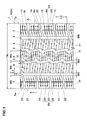
- Pneumatic tire 1 comprises, as usual, a tread portion 2, a pair of axially spaced bead portions each with a bead core therein, a pair of sidewall portions extending between the tread edges Te and the bead portions, a carcass extending between the bead portions, and a tread reinforcing belt disposed radially outside the carcass in the tread portion.
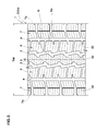
- the tread portion 2 is provided with circumferentially continuously extending main grooves 3 and 4 which are a pair of crown main grooves 3 disposed one on each side of the tire equator C, and a pair of shoulder main grooves 4 disposed axially outside the respective crown main grooves 3.
- the crown main groove 3 in this example is a zigzag groove.
- the width W3 of the crown main groove 3 is set in a range of from 2.0 to 6.0 % of the tread width TW in order to improve wet performance during running in wet conditions by effectively draining water existing between the tread 2s and the road surface.
- the shoulder main groove 4 in this example is a straight groove whose each edge extends along a straight line parallel width the tire equator.
- the width W4 of the shoulder main groove 4 is set in a range of from 2.0 to 6.0 % of the tread width TW in order to increase the shearing force of snow packed into the groove during running on snowy roads, in particular, to improve the cornering performance on snowy roads.
- the depth D1 of the crown main groove 3 and the depth D2 of the shoulder main groove 4 are set in a range of from 10 to 15 mm in order to increase the wet performance, snow performance and steering stability.
- the tread portion 2 is axially divided into five land zones, namely, a center land zone 5 between the two main grooves 3, a pair of middle land zones 6 between the main grooves 3 and the main grooves 4, and a pair of shoulder land zones 7 between the main grooves 4 and the tread edges Te.
- the center land zone 5 in this example extends zigzag.
- the center land zone 5 is provided with sipes 31 defined as having a width of 0.5 to 1.0 mm.
- the center land zone 5 is provided with no grooves other than the sipes 31. Thus, the center land zone 5 extends substantially continuously in the tire circumferential direction, therefore, this portion may be considered as a rib.
- the maximum axial width W5 of the center land zone 5 is set in a range of from 0.14 to 0.18 times the tread width TW in order to increase the rigidity and thereby improve the steering stability during running on dry roads.
- the middle land zones 6 are each provided with middle axial grooves 10 arranged circumferentially of the tire at intervals, and thereby the middle land zone 6 is circumferentially divided into middle blocks 14 in a circumferential row.
- the middle land zone 6 has an axially inner edge 6i circumferentially extending zigzag and an axially outer edge 6o circumferentially extending straight.
- the maximum axial width W6 of the middle land zone 6 is set in a range of from 0.15 to 0.20 times the tread width TW.
- the middle land zone 6 is provided with middle axial grooves 10 and middle auxiliary grooves 11 arranged alternately in the circumferential direction at intervals.
- the middle axial groove 10 is connected to the adjacent main grooves 3 and 4.
- the middle axial groove 10 is inclined with respect to the tire axial direction.
- the inclination angle ⁇ 1 of the middle axial groove 10 is set in a range of from 5 to 10 degrees with respect to the tire axial direction.
- the width W7 of the middle axial groove 10 is substantially constant.
- the width W7 of the middle axial groove 10 is set in a range of from 0.40 to 0.50 times the width W4 of the shoulder main groove 4.
- the depth D3 of the middle axial groove 10 is preferably set in a range of not less than 0.70 times, more preferably not less than 0.73 times, but not more than 0.80 times, more preferably not more than 0.77 times the depth D2 of the shoulder main groove 4 in order to improve the wet performance without sacrificing the rigidity of the tread portion 2.
- middle auxiliary grooves 11 each have an axially outer end 12 connected to the shoulder main groove 4, and an axially inner end 13 terminating within the middle land zone 6.
- Such middle auxiliary grooves 11 can maintain the ground contacting area of the middle land zone 6 in its axially inside part in order to improve ice performance, and at the same time, can increase the shearing force of packed snow in order to improve snow performance.
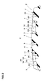
- the width w8 of the middle auxiliary groove 11 is gradually increased from the axial inside toward the axially outside of the tire in order that snow is effectively packed tight during cornering and thereby improve the shearing force. If the width w8 of the middle auxiliary groove 11 is large, the rigidity of the middle land zone 6 decreases, and there is a possibility that the steering stability on icy roads deteriorates. If the width W8 of the middle auxiliary groove 11 is small, there is a possibility that the shearing force of packed snow is not increased.
- the width W8 of the middle auxiliary groove 11 is preferably set in a range of not less than 0.40 times, more preferably not less than 0.45 times, but not more than 0.60 times, more preferably not more than 0.55 times the width W4 of the shoulder main groove 4.
- the axial length L1 of the middle auxiliary groove 11 is preferably set in a range of not less than 0.25 times, more preferably not less than 0.28 times, but not more than 0.35 times, more preferably not more than 0.32 times the maximum width W6 of the middle land zone 6.
- the middle auxiliary grooves 11 can increase the shearing force of packed snow, while maintaining the rigidity of the middle land zone 6, and it becomes possible to improve the snow performance and ice performance in a good balance.
- the widthwise center line 11c of the middle auxiliary groove 11 is inclined with respect to the tire axial direction in order that the middle auxiliary groove 11 can exert its edge effect in multi-directions to thereby improve the steering stability on icy roads and snowy roads.
- the angle ⁇ 2 of the widthwise center line 11c of the middle auxiliary groove 11 is preferably set in a range of not less than 3 degrees, more preferably not less than 5 degrees, but not more than 10 degrees, more preferably not more than 8 degrees with respect to the tire axial direction.
- the depth D4 of the middle auxiliary groove 11 is preferably set in a range of not less than 0.45 times, more preferably not less than 0.50 times, but not more than 0.60 times, more preferably not more than 0.55 times the depth D2 of the shoulder main groove 4.
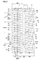
- the shoulder land zone 7 is, as shown in Fig.3 , formed as a row of circumferentially arranged shoulder blocks 21 divided by shoulder axial grooves 20 arranged circumferentially of the tire at intervals.
- the width W9 of the shoulder land zone 7 is substantially constant.
- the width W9 of the shoulder land zone 7 is set in a range of fromO.13 to 0.20 times the tread width TW.
- the shoulder land zone 7 is further provided with shoulder narrow grooves 22 each connected to the circumferentially adjacent shoulder axial grooves 20.
- the shoulder axial groove 20 has an axially inner end 20i connected to the shoulder main groove 4, and an axially outer end 20o opened at the tread edge Te, and the groove width W11 at the axially outer end 20o is larger than the groove width W10 at the axially inner end 20i.
- Such shoulder axial grooves 20 relatively increase the ground contacting area of the shoulder land zone 7 in its axially inside part where the ground pressure is relatively high, therefore, the friction of the shoulder land zone 7 increases and ice performance is improved. Further, the shoulder axial grooves 20 relatively increases the groove volume in an axially outside part of the shoulder land zone 7 where the ground pressure is relatively low, therefore, the decrease in the frictional force of the shoulder land zone 7 can be minimized and the shearing force of packed snow is increased to improve snow performance.
- the middle auxiliary grooves 11 continue to the respective shoulder axial grooves 20 through the shoulder main groove 4.
- their opposite ends are aligned so that, in the tire circumferential direction, the axially inner end 20i of the shoulder axial groove 20 is at least partially overlapped with the axially outer end 12 of the middle auxiliary groove 11. Therefore, during running on snowy roads, snow packed into the middle auxiliary grooves 11 and the shoulder axial grooves 20 extends continuously long in the tire axial direction, and accordingly, a larger shearing force can be obtained to improve snow performance.
- the shoulder axial groove 20 comprises a first portion 23 extending axially outwardly from the shoulder main groove 4, and a second portion 24 extending axially outwardly from the first portion 23 and having a groove width W2 more than the groove width W1 of the first portion 23.
- the first portion 23 extends straight and is inclined with respect to the tire axial direction.
- the angle ⁇ 3 of the first portion 23 is preferably set in a range of not less than 5 degrees, more preferably not less than 10 degrees, but not more than 25 degrees, more preferably not more than 20 degrees with respect to the tire axial direction in order that the edge effect is exerted in the tire circumferential direction and axial direction to improve the steering stability on icy roads.
- the width W1 of the first portion 23 is substantially constant. But, it is also possible to increase the groove width W1 gradually from the axially inside toward the outside in order to effectively discharge water toward the axially outside. If the groove width W1 of the first portion 23 is small, the shearing force of packed snow decreases and it becomes difficult to improve the snow performance. If the groove width W1 of the first portion 23 is large, the ground contacting area of the shoulder land zone 7 decreases and it becomes difficult to improve the ice performance.
- the groove width W1 of the first portion 23 is preferably set in a range of not less than 0.10 times, more preferably not less than 0.15 times, but not more than 0.30 times, more preferably not more than 0.17 times the maximum circumferential length L2 of the shoulder block 21.
- the axial length L3 of the first portion 23 is preferably set in a range of not less than 0.40 times, more preferably not less than 0.45 times, but not more than 0.60 times, more preferably not more than 0.55 times the width W9 of the shoulder land zone 7 in order that the edge effect is exerted in the tire circumferential direction and axial direction in a good balance to improve the steering stability on icy roads especially.
- the groove depth D5 of the first portion 23 is set in a range of not less than 0.45 times, more preferably not less than 0.50 times, but not more than 0.60 times, more preferably not more than 0.55 times the depth D2 of the shoulder main groove 4, and the groove depth D5 of the first portion 23 is preferably equal to the depth D4 of the middle auxiliary groove 11 in order to increase the shearing force of packed snow, while maintaining the rigidity of the shoulder land zone 7.
- the second portion 24 extends straight as shown in Fig.3 .
- the second portion 24 is parallel with the tire axial direction in order to increase the shearing force of packed snow in the tire circumferential direction and improve the steering stability on snowy roads.
- the groove width W2 of the second portion 24 is substantially constant. But, it is also possible to gradually increase the groove width W2 from the axially inside towards the outside in order that the shearing force of packed snow is increased toward the axially outside and to thereby improve the cornering performance on snowy roads.
- the groove width w2 of the second portion 24 is preferably set in a range of not less than 0.17 times, more preferably not less than 0.20 times, but not more than 0.33 times, more preferably not more than 0.23 times the maximum circumferential length L2 of the shoulder block 21.
- the ratio W2/W1 of the width w2 to the width W1 is preferably set in a range of not less than 1.10, more preferably not less than 1.30, but not more than 1.70, more preferably not more than 1.50.
- the axial length L4 of the second portion 24 is preferably set in a range of not less than 0.32 times, more preferably not less than 0.37 times, but not more than 0.52 times, more preferably not more than 0.47 times the width W9 of the shoulder land zone.
- the groove depth D6 of the second portion 24 is more than the groove depth D5 of the first portion 23, and it is preferable that the groove depth D6 of the second portion 24 is not less than 1.40 times, more preferably not less than 1.45 times, but not more than 1.60 times, more preferably not more than 1.55 times the groove depth D5 of the first portion 23 in order to increase the drainage and effectively improve the wet performance.
- the shoulder axial groove 20 has a third portion 25 which has a groove width more than the second portion 24, and to which the axially outer end 24o of the second portion 24 is connected in order to improve the wandering performance on dry roads and improve the wet performance.
- the shoulder narrow groove 22 extends straight in the tire circumferential direction with a substantially constant groove width W14.
- each end of the shoulder narrow groove 22 is connected to the junction 28 between the first portion 23 and the second portion 24 of the adjacent shoulder axial groove 20 in order to effectively drain water existing between the shoulder land zone 7 and the road surface and improve the wet performance during running in wet conditions.
- the width W14 of the shoulder narrow groove 22 is small. If the width W14 of the shoulder narrow groove 22 is large, there is a possibility that the rigidity of the shoulder land zone 7 is decreased and steering stability is deteriorated.
- the width W14 of the shoulder narrow groove 22 is preferably set in a range of not less than 0.18 times, more preferably not less than 0.20 times, but not more than 0.26 times, more preferably not more than 0.24 times the width W4 of the shoulder main groove 4.
- the depth D7 of the shoulder narrow groove 22 is preferably set in a range of not less than 0.45 times, more preferably not less than 0.50 times, but not more than 0.60 times, more preferably not more than 0.55 times the depth D2 of the shoulder main groove 4.
- the shoulder blocks 21 each include an inside block 26 axially inside the shoulder narrow groove 22 and an outside block 27 axially outside the shoulder narrow groove 22.
- the top surface 26s of the inside block 26 is formed in a substantially parallelogram.
- the circumferential length L5 of the inside block 26 is preferably set in a range of not less than 0.90 times, more preferably not less than 0.95 times, but not more than 1.1 times, more preferably not more than 1.05 times the width W9 of the shoulder land zone 7 in order to optimize the rigidity of the shoulder land zone 7 and improve the ice performance.
- the top surface 27s of the outside block 27 is formed in a substantially rectangular shape.
- the circumferential length L6 of the outside block 27 is preferably set in a range of not less than 0.75 times, more preferably not less than 0.80 times, but not more than 0.95 times, more preferably not more than 0.90 times the circumferential length L5 of the inside block 26 in order to improve the snow performance and the ice performance at the same time and improve the wandering performance.
- the shoulder blocks 21 are each provided with sipes 31 having a groove width of 0.5 to 1.0 mm in order to improve the ice performance.
- the sipe 31 has an end 29 connected to the shoulder narrow groove 22, and an end 30 terminating within the shoulder block 21.
- the sipes 31 are parallel with the edges 21e of the shoulder block 21 in the tire circumferential direction in order to prevent the block from getting chipped and in order that the sipes 31 can exert the edge effect in the same direction as the shoulder axial groove 20 to improve the snow performance and ice performance.
- the sipes 31 are arranged at intervals in the tire circumferential direction.
- inside block 26 and outside block 27 are each provided with four sipes 31.
- the sipes 31 are arranged at regular intervals in the tire circumferential direction in order to even the rigidity of the shoulder block 21 and prevent the block from getting chipped.
- the middle land zone 6 may be provided with the sipes 31 in order to further improve the snow performance and ice performance.
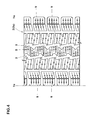
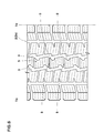
- Fig.4 shows another embodiment of the present invention in which the center land zone 5 is formed as a row of center blocks 9 arranged circumferentially of the tire in order to further improve the snow performance.
- the center blocks 9 are circumferentially divided by center axial grooves 8 extending from one of the crown main grooves 3 to the other.
- Fig.5 shows another embodiment of the present invention in which the center land zone 5, the middle land zones 6 and the shoulder land zones 7 are each provided with zigzag sipes 32 in order that the sipes 32 exert the edge effect in multi-directions to further improve the snow performance.
- pneumatic tires of size 195/80R15 (rim size 15x6.0J) having the specifications shown in Table 1 were prepared and tested for the snow performance and ice performance.
- pneumatic tires of size 195/80R15 having the specifications shown in Table 2 were prepared and tested for the snow performance and ice performance. Specifications common to all of the tires are as follows:
- Ice performance test when a test car was running on an icy road at a speed of 30 km/h, the brake was fully applied, and the braking distance was measured.
- Snow performance test During the test car was running on a snowy road covered with trodden snow, the snow performance (steering responsiveness, braking power, drive power etc.) was evaluated by the test driver.
- the results are indicated in Table 1 and Table 2 by an index based on comparative example tire Ref.1 (in Table 1) and comparative example tire Ref.1R (in Table 2) being 100. The larger index number is better.
Landscapes
- Engineering & Computer Science (AREA)
- Mechanical Engineering (AREA)
- Tires In General (AREA)
Claims (8)
- Luftreifen (1), umfassend
einen Laufflächenabschnitt (2), der auf jeder Seite des Reifenäquators mit einer Kronenhauptrille (3) und einer Schulterhauptrille (4) versehen ist, die sich durchgehend in der Umfangsrichtung des Reifens erstrecken, so dass der Laufflächenabschnitt axial in eine zentrale Landzone (5) zwischen den Kronenhauptrillen, ein Paar mittlere Landzonen (6) zwischen den Kronenhauptrillen und den Schulterhauptrillen und ein Paar Schulterlandzonen (7) axial außerhalb der Schulterhauptrillen unterteilt ist, wobei
die mittleren Landzonen (6) jeweils mit einer Mehrzahl von mittleren Zusatzrillen (11) versehen sind, die sich von der Schulterhauptrille (4) axial nach innen erstrecken und innerhalb der mittleren Landzone enden,
die Schulterlandzonen (7) jeweils mit einer Mehrzahl von axialen Schulterrillen (20) versehen sind, die sich von der Schulterhauptrille axial nach außen erstrecken, dadurch gekennzeichnet, dass
die Breite W11 der axialen Schulterrille (20), an dem axial äußeren Ende (20o) gemessen, größer ist als die Breite W10 der axialen Schulterrille, an dem axial inneren Ende (20i) gemessen, und
die axial inneren Enden (20i) der axialen Schulterrillen jeweils die axial äußeren Enden (12) der mittleren Zusatzrillen (11) zumindest teilweise in der Umfangsrichtung des Reifens überlappen. - Luftreifen nach Anspruch 1, wobei die axiale Schulterrille (20) einen ersten Abschnitt (23), der sich von der Schulterhauptrille (4) axial nach außen erstreckt, und einen zweiten Abschnitt (24) umfasst, der sich von dem ersten Abschnitt mit einer Rillenbreite W2, die größer ist als die Rillenbreite W1 des ersten Abschnitts, axial nach außen erstreckt.
- Luftreifen nach Anspruch 2, wobei die axiale Schulterrille einen dritten Abschnitt (25) umfasst, mit welchem das axial äußere Ende (24o) des zweiten Abschnitts verbunden ist und der eine Rillenbreite W11 aufweist, die größer ist als die des zweiten Abschnitts.
- Luftreifen nach Anspruch 2 oder 3, wobei
jede der Schulterlandzonen (7) Schulterblöcke (21) umfasst, die durch die axialen Schulterrillen (20) abgeteilt sind,
die Rillenbreite W1 des ersten Abschnitts (23) das 0,10- bis 0,30-fache der maximalen Umfangslänge L2 des Schulterblocks (21) beträgt, und
die Rillenbreite W2 des zweiten Abschnitts (24) das 0,17- bis 0,33-fache der maximalen Umfangslänge L2 des Schulterblocks (21) beträgt. - Luftreifen nach Anspruch 4, wobei das Verhältnis W2/W1 der Rillenbreite W2 des zweiten Abschnitts zu der Rillenbreite W1 des ersten Abschnitts in einem Bereich von nicht weniger als 1,10, aber nicht mehr als 1,70 liegt.
- Luftreifen nach einem der Ansprüche 2-5, wobei der erste Abschnitt (23) mit Bezug auf die axiale Richtung des Reifens geneigt ist, und der zweite Abschnitt (24) parallel zu der axialen Richtung des Reifens liegt.
- Luftreifen nach Anspruch 6, wobei der erste Abschnitt (23) unter einem Winkel von 5 bis 25 Grad mit Bezug auf die axiale Richtung des Reifens geneigt ist.
- Luftreifen nach einem der Ansprüche 2-7, wobei jede der Schulterlandzonen (7) mit einer Mehrzahl von schmalen Schulterrillen (22) versehen ist, die sich jeweils von dem Übergang (28) zwischen dem ersten Abschnitt (23) und dem zweiten Abschnitt (24) von einer der schmalen Schulterrillen zu dem Übergang der benachbarten schmalen Schulterrille mit einer Rillenbreite W14, die kleiner ist als die der Schulterhauptrille (4), erstrecken.
Applications Claiming Priority (2)
| Application Number | Priority Date | Filing Date | Title |
|---|---|---|---|
| JP2013013557 | 2013-01-28 | ||
| JP2013117157A JP5852608B2 (ja) | 2013-01-28 | 2013-06-03 | 空気入りタイヤ |
Publications (2)
| Publication Number | Publication Date |
|---|---|
| EP2759417A1 EP2759417A1 (de) | 2014-07-30 |
| EP2759417B1 true EP2759417B1 (de) | 2015-11-18 |
Family
ID=49886848
Family Applications (1)
| Application Number | Title | Priority Date | Filing Date |
|---|---|---|---|
| EP14150369.8A Not-in-force EP2759417B1 (de) | 2013-01-28 | 2014-01-07 | Luftreifen |
Country Status (4)
| Country | Link |
|---|---|
| US (1) | US9561688B2 (de) |
| EP (1) | EP2759417B1 (de) |
| JP (1) | JP5852608B2 (de) |
| CN (1) | CN103963570B (de) |
Families Citing this family (17)
| Publication number | Priority date | Publication date | Assignee | Title |
|---|---|---|---|---|
| US9757991B2 (en) * | 2013-02-19 | 2017-09-12 | Sumitomo Rubber Industries, Ltd. | Pneumatic tire |
| JP6190194B2 (ja) * | 2013-07-22 | 2017-08-30 | 住友ゴム工業株式会社 | 空気入りタイヤ |
| JP6462309B2 (ja) * | 2014-10-23 | 2019-01-30 | 住友ゴム工業株式会社 | 空気入りタイヤ |
| CN104827831B (zh) * | 2015-05-20 | 2017-03-01 | 青岛双星轮胎工业有限公司 | 具有对称花纹的全天候轮胎 |
| DE102015214483A1 (de) * | 2015-07-30 | 2017-02-02 | Continental Reifen Deutschland Gmbh | Fahrzeugluftreifen |
| JP6558124B2 (ja) * | 2015-07-31 | 2019-08-14 | 住友ゴム工業株式会社 | 空気入りタイヤ |
| USD796423S1 (en) * | 2015-08-18 | 2017-09-05 | Bridgestone Americas Tire Operations, Llc | Tire tread |
| JP6699193B2 (ja) * | 2016-01-21 | 2020-05-27 | 住友ゴム工業株式会社 | 空気入りタイヤ |
| JP6711172B2 (ja) * | 2016-06-27 | 2020-06-17 | 住友ゴム工業株式会社 | タイヤ |
| JP6885176B2 (ja) * | 2017-04-18 | 2021-06-09 | 住友ゴム工業株式会社 | タイヤ |
| JP6922547B2 (ja) * | 2017-08-21 | 2021-08-18 | 住友ゴム工業株式会社 | タイヤ |
| JP7078389B2 (ja) * | 2017-12-13 | 2022-05-31 | Toyo Tire株式会社 | 空気入りタイヤ |
| JP7106982B2 (ja) * | 2018-05-22 | 2022-07-27 | 住友ゴム工業株式会社 | タイヤ |
| JP7640314B2 (ja) * | 2021-03-19 | 2025-03-05 | Toyo Tire株式会社 | 空気入りタイヤ |
| US12420591B2 (en) * | 2021-05-05 | 2025-09-23 | The Goodyear Tire & Rubber Company | Tire tread |
| JP7797867B2 (ja) * | 2021-12-27 | 2026-01-14 | 住友ゴム工業株式会社 | タイヤ |
| JP7846578B2 (ja) | 2022-07-05 | 2026-04-15 | Toyo Tire株式会社 | 空気入りタイヤ |
Family Cites Families (23)
| Publication number | Priority date | Publication date | Assignee | Title |
|---|---|---|---|---|
| EP0466998B1 (de) * | 1990-07-20 | 1994-11-02 | The Goodyear Tire & Rubber Company | Reifenlaufflächen |
| JP2804710B2 (ja) * | 1993-12-28 | 1998-09-30 | 住友ゴム工業株式会社 | 空気入りタイヤ |
| JPH11129709A (ja) * | 1997-10-30 | 1999-05-18 | Toyo Tire & Rubber Co Ltd | 空気入りタイヤ |
| JP4149034B2 (ja) * | 1998-06-02 | 2008-09-10 | 住友ゴム工業株式会社 | 車両用タイヤ |
| JP2001138716A (ja) * | 1999-11-17 | 2001-05-22 | Bridgestone Corp | 空気入りタイヤ |
| ES2248152T3 (es) * | 1999-12-01 | 2006-03-16 | Pirelli Pneumatici Societa Per Azioni | Neumatico para ruedas de vehiculos. |
| US20100132864A1 (en) * | 2006-12-21 | 2010-06-03 | Gianfranco Colombo | Tyre for vehicle wheels having improved tread pattern |
| JP4217266B1 (ja) * | 2007-08-07 | 2009-01-28 | 住友ゴム工業株式会社 | 空気入りタイヤ |
| JP4582153B2 (ja) * | 2008-01-28 | 2010-11-17 | 横浜ゴム株式会社 | 空気入りタイヤ |
| JP4510906B2 (ja) | 2008-05-08 | 2010-07-28 | 住友ゴム工業株式会社 | 空気入りタイヤ |
| JP4397954B2 (ja) * | 2008-06-13 | 2010-01-13 | 横浜ゴム株式会社 | 空気入りタイヤ |
| JP4442709B2 (ja) * | 2008-09-12 | 2010-03-31 | 横浜ゴム株式会社 | 空気入りタイヤ |
| JP4471031B1 (ja) * | 2009-02-16 | 2010-06-02 | 横浜ゴム株式会社 | 空気入りタイヤ |
| JP5404378B2 (ja) * | 2009-12-28 | 2014-01-29 | 株式会社ブリヂストン | 空気入りタイヤ |
| JP5018981B2 (ja) * | 2010-11-15 | 2012-09-05 | 横浜ゴム株式会社 | 空気入りタイヤ |
| JP5291739B2 (ja) * | 2011-03-02 | 2013-09-18 | 住友ゴム工業株式会社 | 空気入りタイヤ |
| JP5438719B2 (ja) * | 2011-04-20 | 2014-03-12 | 住友ゴム工業株式会社 | 空気入りタイヤ |
| JP5452561B2 (ja) * | 2011-09-16 | 2014-03-26 | 住友ゴム工業株式会社 | 空気入りタイヤ |
| JP5083451B1 (ja) * | 2011-12-07 | 2012-11-28 | 横浜ゴム株式会社 | 空気入りタイヤ |
| JP5932618B2 (ja) * | 2012-11-20 | 2016-06-08 | 住友ゴム工業株式会社 | 空気入りタイヤ |
| JP5898646B2 (ja) * | 2013-02-15 | 2016-04-06 | 住友ゴム工業株式会社 | 空気入りタイヤ |
| JP5834031B2 (ja) * | 2013-02-21 | 2015-12-16 | 住友ゴム工業株式会社 | 空気入りタイヤ |
| JP5732089B2 (ja) * | 2013-02-26 | 2015-06-10 | 住友ゴム工業株式会社 | 空気入りタイヤ |
-
2013
- 2013-06-03 JP JP2013117157A patent/JP5852608B2/ja active Active
- 2013-12-23 CN CN201310717346.9A patent/CN103963570B/zh not_active Expired - Fee Related
-
2014
- 2014-01-07 EP EP14150369.8A patent/EP2759417B1/de not_active Not-in-force
- 2014-01-13 US US14/153,139 patent/US9561688B2/en not_active Expired - Fee Related
Also Published As
| Publication number | Publication date |
|---|---|
| JP5852608B2 (ja) | 2016-02-03 |
| US20140209225A1 (en) | 2014-07-31 |
| CN103963570B (zh) | 2017-04-12 |
| EP2759417A1 (de) | 2014-07-30 |
| CN103963570A (zh) | 2014-08-06 |
| US9561688B2 (en) | 2017-02-07 |
| JP2014159261A (ja) | 2014-09-04 |
Similar Documents
| Publication | Publication Date | Title |
|---|---|---|
| EP2759417B1 (de) | Luftreifen | |
| EP3000621B1 (de) | Luftreifen | |
| EP3025879B1 (de) | Luftreifen | |
| EP2664464B1 (de) | Luftreifen | |
| EP3296127B1 (de) | Luftreifen | |
| EP2578418B1 (de) | Luftreifen | |
| US10286732B2 (en) | Tire | |
| EP3056359B1 (de) | Luftreifen | |
| EP3093162B1 (de) | Luftreifen | |
| EP3095623B1 (de) | Luftreifen | |
| EP2732985B1 (de) | Luftreifen | |
| EP2511107B1 (de) | Luftreifen | |
| US9522574B2 (en) | Pneumatic tire with tread having sipes | |
| EP2289714B1 (de) | Pneu | |
| EP2281698B1 (de) | Luftreifen | |
| EP3015288B1 (de) | Luftreifen | |
| EP2660078B1 (de) | Luftreifen | |
| EP3012119B1 (de) | Luftreifen | |
| EP2982520B1 (de) | Luftreifen | |
| EP2767415B1 (de) | Luftreifen | |
| EP2439083A2 (de) | Luftreifen | |
| EP3260308A1 (de) | Reifen | |
| EP2522531B1 (de) | Luftreifen | |
| EP2591923A2 (de) | Luftreifen | |
| EP3335910B1 (de) | Reifen |
Legal Events
| Date | Code | Title | Description |
|---|---|---|---|
| PUAI | Public reference made under article 153(3) epc to a published international application that has entered the european phase |
Free format text: ORIGINAL CODE: 0009012 |
|
| 17P | Request for examination filed |
Effective date: 20140107 |
|
| AK | Designated contracting states |
Kind code of ref document: A1 Designated state(s): AL AT BE BG CH CY CZ DE DK EE ES FI FR GB GR HR HU IE IS IT LI LT LU LV MC MK MT NL NO PL PT RO RS SE SI SK SM TR |
|
| AX | Request for extension of the european patent |
Extension state: BA ME |
|
| R17P | Request for examination filed (corrected) |
Effective date: 20150122 |
|
| RBV | Designated contracting states (corrected) |
Designated state(s): AL AT BE BG CH CY CZ DE DK EE ES FI FR GB GR HR HU IE IS IT LI LT LU LV MC MK MT NL NO PL PT RO RS SE SI SK SM TR |
|
| GRAP | Despatch of communication of intention to grant a patent |
Free format text: ORIGINAL CODE: EPIDOSNIGR1 |
|
| RIC1 | Information provided on ipc code assigned before grant |
Ipc: B60C 11/03 20060101AFI20150717BHEP |
|
| INTG | Intention to grant announced |
Effective date: 20150818 |
|
| GRAS | Grant fee paid |
Free format text: ORIGINAL CODE: EPIDOSNIGR3 |
|
| GRAA | (expected) grant |
Free format text: ORIGINAL CODE: 0009210 |
|
| AK | Designated contracting states |
Kind code of ref document: B1 Designated state(s): AL AT BE BG CH CY CZ DE DK EE ES FI FR GB GR HR HU IE IS IT LI LT LU LV MC MK MT NL NO PL PT RO RS SE SI SK SM TR |
|
| REG | Reference to a national code |
Ref country code: GB Ref legal event code: FG4D |
|
| REG | Reference to a national code |
Ref country code: CH Ref legal event code: EP |
|
| REG | Reference to a national code |
Ref country code: AT Ref legal event code: REF Ref document number: 761341 Country of ref document: AT Kind code of ref document: T Effective date: 20151215 |
|
| REG | Reference to a national code |
Ref country code: IE Ref legal event code: FG4D |
|
| REG | Reference to a national code |
Ref country code: DE Ref legal event code: R096 Ref document number: 602014000433 Country of ref document: DE |
|
| REG | Reference to a national code |
Ref country code: FR Ref legal event code: PLFP Year of fee payment: 3 |
|
| REG | Reference to a national code |
Ref country code: NL Ref legal event code: MP Effective date: 20160218 |
|
| REG | Reference to a national code |
Ref country code: LT Ref legal event code: MG4D |
|
| REG | Reference to a national code |
Ref country code: AT Ref legal event code: MK05 Ref document number: 761341 Country of ref document: AT Kind code of ref document: T Effective date: 20151118 |
|
| PG25 | Lapsed in a contracting state [announced via postgrant information from national office to epo] |
Ref country code: NL Free format text: LAPSE BECAUSE OF FAILURE TO SUBMIT A TRANSLATION OF THE DESCRIPTION OR TO PAY THE FEE WITHIN THE PRESCRIBED TIME-LIMIT Effective date: 20151118 Ref country code: IS Free format text: LAPSE BECAUSE OF FAILURE TO SUBMIT A TRANSLATION OF THE DESCRIPTION OR TO PAY THE FEE WITHIN THE PRESCRIBED TIME-LIMIT Effective date: 20160318 Ref country code: NO Free format text: LAPSE BECAUSE OF FAILURE TO SUBMIT A TRANSLATION OF THE DESCRIPTION OR TO PAY THE FEE WITHIN THE PRESCRIBED TIME-LIMIT Effective date: 20160218 Ref country code: ES Free format text: LAPSE BECAUSE OF FAILURE TO SUBMIT A TRANSLATION OF THE DESCRIPTION OR TO PAY THE FEE WITHIN THE PRESCRIBED TIME-LIMIT Effective date: 20151118 Ref country code: LT Free format text: LAPSE BECAUSE OF FAILURE TO SUBMIT A TRANSLATION OF THE DESCRIPTION OR TO PAY THE FEE WITHIN THE PRESCRIBED TIME-LIMIT Effective date: 20151118 Ref country code: IT Free format text: LAPSE BECAUSE OF FAILURE TO SUBMIT A TRANSLATION OF THE DESCRIPTION OR TO PAY THE FEE WITHIN THE PRESCRIBED TIME-LIMIT Effective date: 20151118 Ref country code: HR Free format text: LAPSE BECAUSE OF FAILURE TO SUBMIT A TRANSLATION OF THE DESCRIPTION OR TO PAY THE FEE WITHIN THE PRESCRIBED TIME-LIMIT Effective date: 20151118 |
|
| PG25 | Lapsed in a contracting state [announced via postgrant information from national office to epo] |
Ref country code: LV Free format text: LAPSE BECAUSE OF FAILURE TO SUBMIT A TRANSLATION OF THE DESCRIPTION OR TO PAY THE FEE WITHIN THE PRESCRIBED TIME-LIMIT Effective date: 20151118 Ref country code: GR Free format text: LAPSE BECAUSE OF FAILURE TO SUBMIT A TRANSLATION OF THE DESCRIPTION OR TO PAY THE FEE WITHIN THE PRESCRIBED TIME-LIMIT Effective date: 20160219 Ref country code: PL Free format text: LAPSE BECAUSE OF FAILURE TO SUBMIT A TRANSLATION OF THE DESCRIPTION OR TO PAY THE FEE WITHIN THE PRESCRIBED TIME-LIMIT Effective date: 20151118 Ref country code: BE Free format text: LAPSE BECAUSE OF NON-PAYMENT OF DUE FEES Effective date: 20160131 Ref country code: SE Free format text: LAPSE BECAUSE OF FAILURE TO SUBMIT A TRANSLATION OF THE DESCRIPTION OR TO PAY THE FEE WITHIN THE PRESCRIBED TIME-LIMIT Effective date: 20151118 Ref country code: AT Free format text: LAPSE BECAUSE OF FAILURE TO SUBMIT A TRANSLATION OF THE DESCRIPTION OR TO PAY THE FEE WITHIN THE PRESCRIBED TIME-LIMIT Effective date: 20151118 Ref country code: PT Free format text: LAPSE BECAUSE OF FAILURE TO SUBMIT A TRANSLATION OF THE DESCRIPTION OR TO PAY THE FEE WITHIN THE PRESCRIBED TIME-LIMIT Effective date: 20160318 Ref country code: RS Free format text: LAPSE BECAUSE OF FAILURE TO SUBMIT A TRANSLATION OF THE DESCRIPTION OR TO PAY THE FEE WITHIN THE PRESCRIBED TIME-LIMIT Effective date: 20151118 Ref country code: FI Free format text: LAPSE BECAUSE OF FAILURE TO SUBMIT A TRANSLATION OF THE DESCRIPTION OR TO PAY THE FEE WITHIN THE PRESCRIBED TIME-LIMIT Effective date: 20151118 |
|
| PG25 | Lapsed in a contracting state [announced via postgrant information from national office to epo] |
Ref country code: CZ Free format text: LAPSE BECAUSE OF FAILURE TO SUBMIT A TRANSLATION OF THE DESCRIPTION OR TO PAY THE FEE WITHIN THE PRESCRIBED TIME-LIMIT Effective date: 20151118 |
|
| REG | Reference to a national code |
Ref country code: DE Ref legal event code: R097 Ref document number: 602014000433 Country of ref document: DE |
|
| PG25 | Lapsed in a contracting state [announced via postgrant information from national office to epo] |
Ref country code: RO Free format text: LAPSE BECAUSE OF FAILURE TO SUBMIT A TRANSLATION OF THE DESCRIPTION OR TO PAY THE FEE WITHIN THE PRESCRIBED TIME-LIMIT Effective date: 20151118 Ref country code: DK Free format text: LAPSE BECAUSE OF FAILURE TO SUBMIT A TRANSLATION OF THE DESCRIPTION OR TO PAY THE FEE WITHIN THE PRESCRIBED TIME-LIMIT Effective date: 20151118 Ref country code: SK Free format text: LAPSE BECAUSE OF FAILURE TO SUBMIT A TRANSLATION OF THE DESCRIPTION OR TO PAY THE FEE WITHIN THE PRESCRIBED TIME-LIMIT Effective date: 20151118 Ref country code: EE Free format text: LAPSE BECAUSE OF FAILURE TO SUBMIT A TRANSLATION OF THE DESCRIPTION OR TO PAY THE FEE WITHIN THE PRESCRIBED TIME-LIMIT Effective date: 20151118 Ref country code: SM Free format text: LAPSE BECAUSE OF FAILURE TO SUBMIT A TRANSLATION OF THE DESCRIPTION OR TO PAY THE FEE WITHIN THE PRESCRIBED TIME-LIMIT Effective date: 20151118 Ref country code: LU Free format text: LAPSE BECAUSE OF FAILURE TO SUBMIT A TRANSLATION OF THE DESCRIPTION OR TO PAY THE FEE WITHIN THE PRESCRIBED TIME-LIMIT Effective date: 20160107 |
|
| PLBE | No opposition filed within time limit |
Free format text: ORIGINAL CODE: 0009261 |
|
| STAA | Information on the status of an ep patent application or granted ep patent |
Free format text: STATUS: NO OPPOSITION FILED WITHIN TIME LIMIT |
|
| PG25 | Lapsed in a contracting state [announced via postgrant information from national office to epo] |
Ref country code: MC Free format text: LAPSE BECAUSE OF FAILURE TO SUBMIT A TRANSLATION OF THE DESCRIPTION OR TO PAY THE FEE WITHIN THE PRESCRIBED TIME-LIMIT Effective date: 20151118 |
|
| 26N | No opposition filed |
Effective date: 20160819 |
|
| REG | Reference to a national code |
Ref country code: IE Ref legal event code: MM4A |
|
| PG25 | Lapsed in a contracting state [announced via postgrant information from national office to epo] |
Ref country code: SI Free format text: LAPSE BECAUSE OF FAILURE TO SUBMIT A TRANSLATION OF THE DESCRIPTION OR TO PAY THE FEE WITHIN THE PRESCRIBED TIME-LIMIT Effective date: 20151118 |
|
| REG | Reference to a national code |
Ref country code: FR Ref legal event code: PLFP Year of fee payment: 4 |
|
| PG25 | Lapsed in a contracting state [announced via postgrant information from national office to epo] |
Ref country code: BE Free format text: LAPSE BECAUSE OF FAILURE TO SUBMIT A TRANSLATION OF THE DESCRIPTION OR TO PAY THE FEE WITHIN THE PRESCRIBED TIME-LIMIT Effective date: 20151118 |
|
| PG25 | Lapsed in a contracting state [announced via postgrant information from national office to epo] |
Ref country code: IE Free format text: LAPSE BECAUSE OF NON-PAYMENT OF DUE FEES Effective date: 20160107 |
|
| PG25 | Lapsed in a contracting state [announced via postgrant information from national office to epo] |
Ref country code: MT Free format text: LAPSE BECAUSE OF FAILURE TO SUBMIT A TRANSLATION OF THE DESCRIPTION OR TO PAY THE FEE WITHIN THE PRESCRIBED TIME-LIMIT Effective date: 20151118 |
|
| REG | Reference to a national code |
Ref country code: CH Ref legal event code: PL |
|
| PG25 | Lapsed in a contracting state [announced via postgrant information from national office to epo] |
Ref country code: LI Free format text: LAPSE BECAUSE OF NON-PAYMENT OF DUE FEES Effective date: 20170131 Ref country code: CH Free format text: LAPSE BECAUSE OF NON-PAYMENT OF DUE FEES Effective date: 20170131 |
|
| REG | Reference to a national code |
Ref country code: FR Ref legal event code: PLFP Year of fee payment: 5 |
|
| PG25 | Lapsed in a contracting state [announced via postgrant information from national office to epo] |
Ref country code: HU Free format text: LAPSE BECAUSE OF FAILURE TO SUBMIT A TRANSLATION OF THE DESCRIPTION OR TO PAY THE FEE WITHIN THE PRESCRIBED TIME-LIMIT; INVALID AB INITIO Effective date: 20140107 Ref country code: CY Free format text: LAPSE BECAUSE OF FAILURE TO SUBMIT A TRANSLATION OF THE DESCRIPTION OR TO PAY THE FEE WITHIN THE PRESCRIBED TIME-LIMIT Effective date: 20151118 |
|
| PG25 | Lapsed in a contracting state [announced via postgrant information from national office to epo] |
Ref country code: MT Free format text: LAPSE BECAUSE OF FAILURE TO SUBMIT A TRANSLATION OF THE DESCRIPTION OR TO PAY THE FEE WITHIN THE PRESCRIBED TIME-LIMIT Effective date: 20160131 Ref country code: TR Free format text: LAPSE BECAUSE OF FAILURE TO SUBMIT A TRANSLATION OF THE DESCRIPTION OR TO PAY THE FEE WITHIN THE PRESCRIBED TIME-LIMIT Effective date: 20151118 Ref country code: MK Free format text: LAPSE BECAUSE OF FAILURE TO SUBMIT A TRANSLATION OF THE DESCRIPTION OR TO PAY THE FEE WITHIN THE PRESCRIBED TIME-LIMIT Effective date: 20151118 |
|
| PG25 | Lapsed in a contracting state [announced via postgrant information from national office to epo] |
Ref country code: BG Free format text: LAPSE BECAUSE OF FAILURE TO SUBMIT A TRANSLATION OF THE DESCRIPTION OR TO PAY THE FEE WITHIN THE PRESCRIBED TIME-LIMIT Effective date: 20151118 |
|
| GBPC | Gb: european patent ceased through non-payment of renewal fee |
Effective date: 20180107 |
|
| PG25 | Lapsed in a contracting state [announced via postgrant information from national office to epo] |
Ref country code: AL Free format text: LAPSE BECAUSE OF FAILURE TO SUBMIT A TRANSLATION OF THE DESCRIPTION OR TO PAY THE FEE WITHIN THE PRESCRIBED TIME-LIMIT Effective date: 20151118 |
|
| PG25 | Lapsed in a contracting state [announced via postgrant information from national office to epo] |
Ref country code: GB Free format text: LAPSE BECAUSE OF NON-PAYMENT OF DUE FEES Effective date: 20180107 |
|
| P01 | Opt-out of the competence of the unified patent court (upc) registered |
Effective date: 20230510 |
|
| PGFP | Annual fee paid to national office [announced via postgrant information from national office to epo] |
Ref country code: FR Payment date: 20231212 Year of fee payment: 11 |
|
| PGFP | Annual fee paid to national office [announced via postgrant information from national office to epo] |
Ref country code: DE Payment date: 20231128 Year of fee payment: 11 |
|
| REG | Reference to a national code |
Ref country code: DE Ref legal event code: R119 Ref document number: 602014000433 Country of ref document: DE |
|
| PG25 | Lapsed in a contracting state [announced via postgrant information from national office to epo] |
Ref country code: DE Free format text: LAPSE BECAUSE OF NON-PAYMENT OF DUE FEES Effective date: 20250801 |
|
| PG25 | Lapsed in a contracting state [announced via postgrant information from national office to epo] |
Ref country code: FR Free format text: LAPSE BECAUSE OF NON-PAYMENT OF DUE FEES Effective date: 20250131 |