EP2759431A2 - Panneau pliant et arceaux pour une structure de toit coulissant d'un camion - Google Patents
Panneau pliant et arceaux pour une structure de toit coulissant d'un camion Download PDFInfo
- Publication number
- EP2759431A2 EP2759431A2 EP13198305.8A EP13198305A EP2759431A2 EP 2759431 A2 EP2759431 A2 EP 2759431A2 EP 13198305 A EP13198305 A EP 13198305A EP 2759431 A2 EP2759431 A2 EP 2759431A2
- Authority
- EP
- European Patent Office
- Prior art keywords
- folding plate
- bow
- folding
- sliding roof
- roof structure
- Prior art date
- Legal status (The legal status is an assumption and is not a legal conclusion. Google has not performed a legal analysis and makes no representation as to the accuracy of the status listed.)
- Withdrawn
Links
- 239000004033 plastic Substances 0.000 claims abstract description 12
- 229920001187 thermosetting polymer Polymers 0.000 claims description 2
- 239000000463 material Substances 0.000 abstract description 4
- 230000007246 mechanism Effects 0.000 description 5
- 238000004519 manufacturing process Methods 0.000 description 3
- 229910052751 metal Inorganic materials 0.000 description 3
- 239000002184 metal Substances 0.000 description 3
- 230000000284 resting effect Effects 0.000 description 3
- XLYOFNOQVPJJNP-UHFFFAOYSA-N water Substances O XLYOFNOQVPJJNP-UHFFFAOYSA-N 0.000 description 3
- 239000004743 Polypropylene Substances 0.000 description 2
- 229910052782 aluminium Inorganic materials 0.000 description 2
- XAGFODPZIPBFFR-UHFFFAOYSA-N aluminium Chemical compound [Al] XAGFODPZIPBFFR-UHFFFAOYSA-N 0.000 description 2
- 238000000034 method Methods 0.000 description 2
- 229920001155 polypropylene Polymers 0.000 description 2
- 230000008569 process Effects 0.000 description 2
- 229910000831 Steel Inorganic materials 0.000 description 1
- 230000008901 benefit Effects 0.000 description 1
- 238000010276 construction Methods 0.000 description 1
- 230000008878 coupling Effects 0.000 description 1
- 238000010168 coupling process Methods 0.000 description 1
- 238000005859 coupling reaction Methods 0.000 description 1
- 230000001419 dependent effect Effects 0.000 description 1
- 238000006073 displacement reaction Methods 0.000 description 1
- 239000000446 fuel Substances 0.000 description 1
- 230000001771 impaired effect Effects 0.000 description 1
- -1 polypropylene Polymers 0.000 description 1
- 230000009467 reduction Effects 0.000 description 1
- 230000002787 reinforcement Effects 0.000 description 1
- 230000006641 stabilisation Effects 0.000 description 1
- 238000011105 stabilization Methods 0.000 description 1
- 239000010959 steel Substances 0.000 description 1
- 239000006228 supernatant Substances 0.000 description 1
Images




Classifications
-
- B—PERFORMING OPERATIONS; TRANSPORTING
- B60—VEHICLES IN GENERAL
- B60J—WINDOWS, WINDSCREENS, NON-FIXED ROOFS, DOORS, OR SIMILAR DEVICES FOR VEHICLES; REMOVABLE EXTERNAL PROTECTIVE COVERINGS SPECIALLY ADAPTED FOR VEHICLES
- B60J7/00—Non-fixed roofs; Roofs with movable panels, e.g. rotary sunroofs
- B60J7/02—Non-fixed roofs; Roofs with movable panels, e.g. rotary sunroofs of sliding type, e.g. comprising guide shoes
- B60J7/06—Non-fixed roofs; Roofs with movable panels, e.g. rotary sunroofs of sliding type, e.g. comprising guide shoes with non-rigid element or elements
- B60J7/061—Non-fixed roofs; Roofs with movable panels, e.g. rotary sunroofs of sliding type, e.g. comprising guide shoes with non-rigid element or elements sliding and folding
- B60J7/064—Non-fixed roofs; Roofs with movable panels, e.g. rotary sunroofs of sliding type, e.g. comprising guide shoes with non-rigid element or elements sliding and folding using folding arms sliding in longitudinal tracks for supporting the soft roof
- B60J7/065—Non-fixed roofs; Roofs with movable panels, e.g. rotary sunroofs of sliding type, e.g. comprising guide shoes with non-rigid element or elements sliding and folding using folding arms sliding in longitudinal tracks for supporting the soft roof for utility vehicles
Definitions
- the invention relates to a folding plate for a sliding roof structure according to the preamble of claim 1 and a bow for a sliding roof structure according to the preamble of claim 12.
- Trucks ie trucks and trailers (trailers) and semi-trailers of trucks, are known in the prior art in various configurations.
- the so-called flatbed cars are known, which have a flat open cargo area behind the driver's cab.
- the cargo area of such flatbed is usually provided with a hood.
- fixed ceilings and sliding covers are known for this purpose. Sliding roofs can be opened, therefore have the advantage over fixed roofs that the loading of the truck, for example, when loading crane, is considerably facilitated by the sliding mechanism, as the cargo space can be made accessible from above or to the side.
- a sliding roof structure is provided with a plurality of hoops, which run transversely to two parallel longitudinal belts, and which are connected to each other along the respective longitudinal belts for forced folding of the resting on the hoops of the sliding roof structure structure via so-called folding plates.
- a top frame for folding a roof tarpaulin which has a multiplicity of hoops which are each connected at their two-sided ends to a carriage which can be moved along lateral longitudinal rails.
- folding means are provided for the forced folding of a tarpaulin resting on the bows.
- the folding means are inserted at the ends in a curved guide of the carriage and perform for erecting a pivoting movement within the curved guide.
- the hoops usually made of steel, the carriages or roller carriages to which the brackets are connected and the tarpaulin itself have a high weight which acts on the folding plates.
- the bows are arranged at the ends of the folding plates and thus remain in the plane of the longitudinal straps when unfolding the tarpaulin, rainwater can accumulate when folding the tarpaulin in so-called water bags, what the weight acting on the folding panels still further increased. This can affect a safe unfolding of the tarpaulin.
- a folding plate for a sliding roof structure of a truck comprising a first Faltplattenelement and a second Faltplattenelement which are respectively connected to a centrally between the first Faltplattenelement and the second Faltplattenelement arranged joint axis element, wherein the hinge axis element comprises a Spriegelanitatis issued. Due to the central arrangement of the Spriegelanitatis worn and thus received therein bow this is raised when unfolding the sliding roof structure and thereby forms a vertex, so that a safe drainage of rain water is guaranteed. Also, with folded top can not form by means of this configuration, no water sacs. As a result, a secure and simple unfolding of the sliding roof structure can be ensured.
- the previously described application of the folding plate for a sliding roof structure of a truck comprises both Application for a powered tractor as well as for a towed trailer or semitrailer.
- the folding plate can also be used for other applications, such as a sliding roof structure of a sightseeing bus or other special vehicle.
- the sunroof structure may be generally associated with road vehicles or rail vehicles, wherein opening or closing of the sunroof structure may be made depending on the arrangement thereof in the vehicle longitudinal or in the vehicle transverse direction.
- the sliding roof structure described above may also be associated with a stationary device such as a container.
- film hinges are provided on the hinge axis element, in particular at least a first film hinge, which hingedly connects the first folding plate element with the hinge axis element, and at least a second film hinge, which connects the second folding plate element articulated to the hinge axis element.
- a first support element is arranged on the first Faltplattenelement and the second Faltplattenelement which is designed to support in the unfolded state of the folding plate on a respectively opposite the first support member on the hinge axis element arranged second support element.
- the first support member is formed as a projection and the second support member as a recess for engaging the projection.
- the second support element preferably has a projection over the first support element in the unfolded state. This ensures that it is ensured when unfolding the folding plate, that the first and the second support element engage with each other.
- the supernatant has a protrusion length in a range of about 20 millimeters.
- the folding plate made of plastic, in particular in one piece, is made. This simplifies the manufacturing and material costs and also reduces the weight of the sliding roof structure.
- a preferred plastic for the production of the folding plate is, for example, polypropylene (PP).
- the at least one first film hinge and the at least one second film hinge each have a curvature.
- the first and second film hinges together form a rounded M-profile.
- a length compensation can be ensured in an advantageous manner.
- the total length of the folding plate can increase, in which flattening the curvature of the film hinges.
- the first and the second film hinge have a material thickness in a range of approximately 2 millimeters.
- the Spriegelanitatis adopted has a receptacle for a bow, which is formed with an element into which the bow is inserted. This allows easy mounting of the bow on the folding plate.
- the receptacle is formed with an element which can be inserted into the bow. Also this configuration provides a simple, fast and safe mounting of the bow to the folding plates.
- the receptacle is formed with a latching device for latching with the bow.
- a latching device for latching with the bow.
- the bow can be secured to the bow binding device by means of a separate latching hook designed as a locking wedge.
- the latching hook preferably engages in a recess of the Spriegelan Kunststoffs founded and thereby prevents slipping out of the bow. Due to the inlet slope of the locking wedge, the bow, which is equipped with such a locking wedge, particularly easy to be inserted into the Spriegelability announced.
- the Spriegelability seen deformed for a short time by the upper cover is pushed up until the locking wedge engages.
- a loosening is possible in a simple manner if, for example, by means of a screwdriver or other similar tool, the upper ceiling is raised, so that the locking wedge is no longer in engagement with the Spriegelanitatis adopted and thus can be pulled out.
- the latching device is formed as a recess in the receptacle for engaging a detent formed on the bow.
- a bow for a sliding roof structure of a truck wherein the bow made of plastic, preferably made of a thermosetting plastic in a pultrusion process, which is also referred to as a Strangziehrea.
- plastic bumper instead of a metal bumper, the overall weight of the sliding roof structure can be significantly reduced. Also, thereby lower material and manufacturing costs are achieved.
- the bow on both sides end portions, which is provided in each case with a latching device, in particular with a latching nose, for latching in a recess provided on a Spriegelanitati.
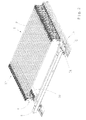
- FIG. 1 shows generally a sliding roof structure 1 for trucks or trailers, which is shown here in the extended or closed state.
- Trucks are understood to mean lorries, lorry trailers and lorry trailers.
- the sliding roof structure 1 comprises a plurality of hoops 2, which are arranged transversely between two mutually parallel longitudinal belts 3, 3 '.
- On the bows 2 is a slide or tarpaulin.
- the trained as rails longitudinal straps 3, 3 ' are integrally made of aluminum and are respectively provided with running surfaces on which a plurality of roller carriage with respective rollers 11 are slidably disposed, of which only a multi-part formed roller carriage 4 with cable connection, a multi-part trained Standard roller carriage 5 and a Endrollenwagen 6 are shown as examples.
- the Endrollenwagen 6 is located at the first end 7 of the sliding roof structure 1, which corresponds to the rear end of a truck on which, for example, a lift is arranged. At the opposite front second end 12 of the sliding roof structure 1 is the closed end, on which, for example, the cab of the truck is arranged. Between the respective longitudinal belts 3 and 3 'arranged Endrollenwagen 6 extends transversely to the longitudinal straps 3, 3' a portal beam 8, which forms the conclusion of the sliding roof structure 1.
- the portal beam 8 serves on the one hand to fix the tarpaulin as a transversely stiffening element on the trailer.
- the portal beam 8 is connected via a connection structure 34 (see FIG. 2 ), Which Lever arms includes, connected to the end roller carriage 6 arranged on both sides, so that by pivoting the lever arms of the gantry beam 8 can be folded up to push back the sliding roof structure 1.
- the gantry beam 8 is designed with an angular shape, so that in the folded-down state it also at least partially overlaps the end-side end faces of the longitudinal straps 3, 3 '.
- a locking mechanism 13, 13 ' is provided in order to prevent displacement of the Endrollenwagens 6 in the end position with the tarpaulin closed.
- a release cable 14 By pulling on a release cable 14, the locking mechanism 13,13 'are released so that then the Endrollenwagen 6 along the longitudinal straps 3, 3' is displaceable.
- a loop 15 is shown for the lateral actuation of the locking mechanism 13, 13 '.
- a rod not shown here, which has an end hook on the loop 15 in the longitudinal direction of the longitudinal straps 3, 3 'and the sliding roof structure 1 thereby opened.
- the end roller carriage 6 are connected to the standard roller carriage 5 via arranged between the respective roller carriage folding plates 9.
- a Spriegelanitatis worn 10 is provided, on which the brackets 2 are attached, so that the brackets 2 are pushed upwards when opening the sliding roof structure 1.
- two roller carriages 4 are provided with cable connection to the opposite roller carriage 4, which serves for the stabilization.
- the folding tarpaulin does not flutter, which would lead to a significantly higher fuel consumption, it has several stanchions, not shown here, which can be releasably connected to the cargo area, for example by being plugged into corresponding recesses.
- stanchions At the top of the stakes with the roller carriage 4, 5 are connected.
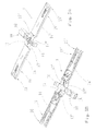
- FIG. 2 shows a perspective view of a front second end 12 of FIG FIG. 1 shown sliding roof structure 1 in the open state, in which the portal beam 8 is pivoted by means of the connecting structure 34 and folded in this state folding plates 9 are each folded, so that the centrally located in the folding plates 9 bow 2 are in a raised position , As can be clearly seen here, the Spriegelanitati 10 is formed centrally in the folding plates 9.
- the collapsed bow 2 including portal beams 8 extend in the state shown here over a length of 1.90 m.
- FIGS. 3A, 3B . 3C show respective views of a plastic folding plate 9 for a sliding roof structure of a truck according to an embodiment, wherein FIG. 3A the folding plate 9 in isometric view from above, FIG. 3B the folding plate 9 in isometric view from below and FIG. 3C the folding plate 9 in unfolded state shows.
- the folding plate 9 has a first folding plate element 14 and a second folding plate element 14 ', which are substantially identical and mirror-symmetrical to a hinge axis element 16, on which the first folding plate element 14 and the second folding plate element 14' respectively articulated are, are arranged.
- the articulated connection of the first folding plate element 14 and the second folding plate element 14 ' takes place via the articulation of the folding plate elements 14, 14' by means of first and second film hinges 17, 17 ', 17 ", 17"' at the center between the first and second folding plate element 14, 14 'arranged joint axis element 16, which has a Spriegelanitatis listening 10.
- the first Faltplattenelement 14 via the film hinges 17 and 17 "with the hinge axis member 16 and der
- the second folding plate element 14 ' is connected to the articulation axis element 16 or the spriegelanitatis observed 10 via the two film hinges 17' and 17 "'for unfolding the sliding roof structure, as shown in FIG.
- the first folding plate member 14 and the second folding plate member 14 ' are pivotable about the hinge axis member 16, respectively, until the two folding plate members 14, 14' are substantially parallel and perpendicular to the yoke coupling means 10.
- a fastening device 18 for a tarpaulin (not shown here) is provided on the joint axis element 16 at the opposite end, which is connectable to a bow.
- a bearing point 20, 20 'for connecting the folding plate 9 is provided on roller carriage not shown here ,
- FIG. 4 shows an isometric view of the in the FIGS. 3A to 3C shown folding plate 9, wherein in the Spriegelanitatis worn 10 a bow 2 is added, as more closely related to FIGS. 5A and 5B will be described.
- FIGS. 5A and 5B are views of a detail in the Spriegelanitatiswitz or by the Spriegelanitatis worn 10 of in FIGS. 3A to 3C illustrated folding plate 9, wherein FIG. 5A is an isometric view of the Spriegelanitatis observed 10 from below and FIG. 5B a sectional view taken along the line AA of FIG. 5A ,
- the Spriegelanitatis worn 10 is equipped with a receptacle 21 which is provided with an element 22, in which the bow 2 can be inserted.
- the receptacle 21 may also be designed to be insertable or receivable into a corresponding recess in the bow 2.
- the receptacle 21 is provided with a latching device 23 (see FIG. 5B ).
- the latching device 23 is formed here as a recess 24, in which a formed on the bow 2 locking lug 25 engages.
- the locking lug 25 is wedge-shaped formed and prevents slipping out of the bow 2 by stop at the position indicated by the reference numeral 26.
- the receptacle 21 deformed briefly by the upper cover 27 moves upward until the latch 25 engages. A loosening is possible vice versa.
- the receptacle 21 can be deformed by introducing, for example, a screwdriver, so that it is no longer in engagement with the locking lug 25 and this is released, so that the bow 2 is easily pulled out.
- FIG. 6 is a sectional view through the in the FIGS. 3A to 3C shown folding plate 9.
- the film hinges 17, 17 ', 17 “, 17”' are each provided with a curvature, which serves for length compensation, as already explained above.
- a support means 28, 28 ' is provided between the first folding plate 14 and the articulation axis element 16 having the flexing connection device 10 and between the second folding plate 14 'and the articulation axis element 10 having the flexing connection device 10, in each case in the region of the film hinges 17, 17 “' and 17 ', 17 ".
- the support device 28, 28 ' each case has a first support element 29, 29', which is provided on the first folding plate element 14 or on the second folding plate element 14 '.
- the support device 28, 28 ' in each case a second support member 30, 30', which on the Spriegelanitatis founded 10 having joint axis member 16 respectively opposite the first support member 29, 29 'on the first Faltplattenelement 14 or on the second Faltplattenelement 14' arranged is.
- FIGS. 7A and 7B are details of the joint area in the FIGS. 3A to 3C illustrated folding plate 9. How particularly good in FIG. 7A can be seen, the first support member 29 and 29 'of the support means 28 and 28' is formed as a projection 31, whereas the second support member 30 or 30 'with a recess 32 for engaging the projection 31 is formed. Furthermore, the second support element 30 or 30 'relative to the first support element 29 or 29' on a projection 33 to secure engagement of the first support member 29 and 29 'with the second support member 30 and 30' to ensure.
- FIGS. 3A to 3C are views of the in the FIGS. 3A to 3C shown folding plate 9, which is mounted on the roller carriage 5, wherein Figure 8A the folding plate 9 in the unfolded state shows and FIG. 8B shows the folding plate 9 in the extended or unfolded state.
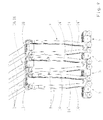
- FIG. 9 shows a plurality of folding plates 9 with incorporated therein hoops 2, wherein the folding plates 9, respectively, as described above, are mounted on the roller carriage 5.
- FIGS. 3A to 3C are respective views of the in the FIGS. 3A to 3C illustrated folding plate 9, which on the roller carriage 5 slidably on a longitudinal belt 3 of a sliding roof structure 1, as shown in FIG FIG. 1 is shown, is arranged.
- the folding plate 9 is shown in a folded state.
Landscapes
- Engineering & Computer Science (AREA)
- Mechanical Engineering (AREA)
- Roof Covering Using Slabs Or Stiff Sheets (AREA)
- Body Structure For Vehicles (AREA)
Applications Claiming Priority (1)
| Application Number | Priority Date | Filing Date | Title |
|---|---|---|---|
| DE102013201000.1A DE102013201000A1 (de) | 2013-01-23 | 2013-01-23 | Faltplatte und Spriegel für eine Schiebeverdeckstruktur eines Lastwagens |
Publications (2)
| Publication Number | Publication Date |
|---|---|
| EP2759431A2 true EP2759431A2 (fr) | 2014-07-30 |
| EP2759431A3 EP2759431A3 (fr) | 2018-10-24 |
Family
ID=49884984
Family Applications (1)
| Application Number | Title | Priority Date | Filing Date |
|---|---|---|---|
| EP13198305.8A Withdrawn EP2759431A3 (fr) | 2013-01-23 | 2013-12-19 | Panneau pliant et arceaux pour une structure de toit coulissant d'un camion |
Country Status (2)
| Country | Link |
|---|---|
| EP (1) | EP2759431A3 (fr) |
| DE (1) | DE102013201000A1 (fr) |
Families Citing this family (6)
| Publication number | Priority date | Publication date | Assignee | Title |
|---|---|---|---|---|
| DE102014013787B4 (de) * | 2014-09-23 | 2019-06-19 | European Trailer Systems Gmbh | Verdeckgestell für eine zusammenschiebbare Plane |
| EP3594036B1 (fr) | 2018-07-13 | 2024-08-21 | Helmut Fliegl | Traverse en une seule pièce pour une structure de véhicule utilitaire ou de remorque |
| PL3744545T3 (pl) | 2019-05-29 | 2022-07-04 | Helmut Fliegl | Wózek końcowy |
| DE102022105105A1 (de) | 2022-03-03 | 2023-09-07 | European Trailer Systems Gmbh | Aufbau für einen Unterbau |
| US20250162490A1 (en) | 2022-03-03 | 2025-05-22 | European Trailer Systems Gmbh | Structure for a substructure |
| DE102022105104A1 (de) | 2022-03-03 | 2023-09-07 | European Trailer Systems Gmbh | Aufbau für einen Unterbau |
Citations (1)
| Publication number | Priority date | Publication date | Assignee | Title |
|---|---|---|---|---|
| DE102005016158B3 (de) | 2005-04-07 | 2006-09-21 | Edscha Lkw-Schiebeverdecke Gmbh | Verdeckgestell für einen Planenaufbau |
Family Cites Families (6)
| Publication number | Priority date | Publication date | Assignee | Title |
|---|---|---|---|---|
| GB2106573B (en) * | 1981-09-15 | 1985-01-16 | Boalloy Ltd | Curtain-sided van bodies |
| DE8709759U1 (de) * | 1987-07-16 | 1988-11-10 | Barbett, Johannes, 4292 Rhede | Schiebeverdeckgestell für Lastfahrzeuge |
| FR2742105B1 (fr) * | 1995-12-08 | 1998-02-20 | Pommier & Cie | Dispositif pour le bachage de vehicules poids lourd |
| US6976433B1 (en) * | 2004-06-10 | 2005-12-20 | Dietmar Neumann | Slidable cover assembly for merchandise carrying vehicle platforms |
| DE102006025754A1 (de) * | 2006-05-31 | 2007-12-06 | Bauregger, Günter | Stützeinrichtung für ein Fahrzeugplanenoberteil einer Fahrzeugplane auf einem Schiebeverdeck eines LKWs oder LKW-Anhängers oder dergleichen |
| BE1019433A5 (nl) * | 2010-07-23 | 2012-07-03 | Vbg Group Truck Equipment N V | Constructie voor een schuifdak, schuifdaksysteem, vrachtwagen met schuifdaksysteem, schuifzeiltrailer met een schuifdaksysteem. |
-
2013
- 2013-01-23 DE DE102013201000.1A patent/DE102013201000A1/de not_active Withdrawn
- 2013-12-19 EP EP13198305.8A patent/EP2759431A3/fr not_active Withdrawn
Patent Citations (1)
| Publication number | Priority date | Publication date | Assignee | Title |
|---|---|---|---|---|
| DE102005016158B3 (de) | 2005-04-07 | 2006-09-21 | Edscha Lkw-Schiebeverdecke Gmbh | Verdeckgestell für einen Planenaufbau |
Also Published As
| Publication number | Publication date |
|---|---|
| EP2759431A3 (fr) | 2018-10-24 |
| DE102013201000A1 (de) | 2014-07-24 |
Similar Documents
| Publication | Publication Date | Title |
|---|---|---|
| EP3439904B1 (fr) | Structure de bâchage | |
| EP2759431A2 (fr) | Panneau pliant et arceaux pour une structure de toit coulissant d'un camion | |
| EP2759432A2 (fr) | Renfort longitudinal pour structure de toit coulissant d'un camion | |
| EP2080654B1 (fr) | Berceau de couverture pour un montage de superstructure | |
| EP2759428A2 (fr) | Chariot à galets latéraux et courroie de guidage avec rail pour une structure de toit coulissant d'une carrosserie de véhicule ou d'un conteneur | |
| CH702380A2 (de) | Anhängerzug. | |
| DE202012104195U1 (de) | Nutzfahrzeugaufbau mit mindestens einer Seitenplane | |
| EP2759433A2 (fr) | Dispositif de déverrouillage pour structure de toit coulissant et structure de toit coulissant | |
| EP2676824B1 (fr) | Structure pour le transports de biens | |
| DE10145000C1 (de) | Seitenwand für einen Lastwagen, Lastanhänger, Sattelauflieger od. dgl. | |
| EP3882083B1 (fr) | Dispositif abaissable de support pour marchandises à transporter, ensemble et procédé de montage | |
| EP2759430B1 (fr) | Structure de toit coulissant | |
| DE2931111C2 (de) | Fahrzeugaufbau mit in horizontaler Richtung unterteilten Seitenwänden | |
| EP2759434A2 (fr) | Chariot à galets et système modulaire d'un chariot à galets pour une structure de toit coulissant d'un camion | |
| DE102014208166A1 (de) | Schiebeverdeckstruktur | |
| DE4006532A1 (de) | Ladepritsche fuer fahrzeug mit wenigstens einer oeffenbaren seitenwand | |
| EP3599119B1 (fr) | Structure de bâche résistante à l'humidité | |
| DE102015111842B4 (de) | Laderaumaufbau | |
| DE102014203693A1 (de) | Faltplatte | |
| EP2684782B1 (fr) | Structure pour le transports de biens | |
| EP3964429B1 (fr) | Structure de bâche et véhicule utilitaire pourvu de bâche à panneaux | |
| DE102012108359B4 (de) | Nutzfahrzeug | |
| EP1516763B1 (fr) | Structure de caisse | |
| EP3219890B1 (fr) | Fermeture de serrage pour loquet pour portes ou hayons de carrosseries de véhicule utilitaire | |
| EP3275710B1 (fr) | Articulation a coulisseau |
Legal Events
| Date | Code | Title | Description |
|---|---|---|---|
| PUAI | Public reference made under article 153(3) epc to a published international application that has entered the european phase |
Free format text: ORIGINAL CODE: 0009012 |
|
| 17P | Request for examination filed |
Effective date: 20131219 |
|
| AK | Designated contracting states |
Kind code of ref document: A2 Designated state(s): AL AT BE BG CH CY CZ DE DK EE ES FI FR GB GR HR HU IE IS IT LI LT LU LV MC MK MT NL NO PL PT RO RS SE SI SK SM TR |
|
| AX | Request for extension of the european patent |
Extension state: BA ME |
|
| RAP1 | Party data changed (applicant data changed or rights of an application transferred) |
Owner name: BOGE ELASTMETALL GMBH |
|
| RIC1 | Information provided on ipc code assigned before grant |
Ipc: B60J 7/06 20060101AFI20180416BHEP |
|
| PUAL | Search report despatched |
Free format text: ORIGINAL CODE: 0009013 |
|
| AK | Designated contracting states |
Kind code of ref document: A3 Designated state(s): AL AT BE BG CH CY CZ DE DK EE ES FI FR GB GR HR HU IE IS IT LI LT LU LV MC MK MT NL NO PL PT RO RS SE SI SK SM TR |
|
| AX | Request for extension of the european patent |
Extension state: BA ME |
|
| RIC1 | Information provided on ipc code assigned before grant |
Ipc: B60J 7/06 20060101AFI20180917BHEP |
|
| STAA | Information on the status of an ep patent application or granted ep patent |
Free format text: STATUS: THE APPLICATION IS DEEMED TO BE WITHDRAWN |
|
| 18D | Application deemed to be withdrawn |
Effective date: 20190425 |