EP2759643A2 - Système de sécurité pour bain - Google Patents
Système de sécurité pour bain Download PDFInfo
- Publication number
- EP2759643A2 EP2759643A2 EP14152479.3A EP14152479A EP2759643A2 EP 2759643 A2 EP2759643 A2 EP 2759643A2 EP 14152479 A EP14152479 A EP 14152479A EP 2759643 A2 EP2759643 A2 EP 2759643A2
- Authority
- EP
- European Patent Office
- Prior art keywords
- bath
- water
- unit
- supply
- discharge
- Prior art date
- Legal status (The legal status is an assumption and is not a legal conclusion. Google has not performed a legal analysis and makes no representation as to the accuracy of the status listed.)
- Withdrawn
Links
Images

Classifications
-
- A—HUMAN NECESSITIES
- A47—FURNITURE; DOMESTIC ARTICLES OR APPLIANCES; COFFEE MILLS; SPICE MILLS; SUCTION CLEANERS IN GENERAL
- A47K—SANITARY EQUIPMENT; ACCESSORIES THEREFOR, e.g. TOILET ACCESSORIES
- A47K3/00—Baths; Showers; Appurtenances therefor
- A47K3/001—Accessories for baths, not provided for in other subgroups of group A47K3/00; Insertions, e.g. for babies; Tubs suspended or inserted in baths; Security or alarm devices; Protecting linings or coverings; Devices for cleaning or disinfecting baths; Bath insulation
-
- E—FIXED CONSTRUCTIONS
- E03—WATER SUPPLY; SEWERAGE
- E03C—DOMESTIC PLUMBING INSTALLATIONS FOR FRESH WATER OR WASTE WATER; SINKS
- E03C1/00—Domestic plumbing installations for fresh water or waste water; Sinks
- E03C1/12—Plumbing installations for waste water; Basins or fountains connected thereto; Sinks
- E03C1/24—Overflow devices for basins or baths
- E03C1/242—Overflow devices for basins or baths automatically actuating supply or draining valves
-
- E—FIXED CONSTRUCTIONS
- E03—WATER SUPPLY; SEWERAGE
- E03C—DOMESTIC PLUMBING INSTALLATIONS FOR FRESH WATER OR WASTE WATER; SINKS
- E03C1/00—Domestic plumbing installations for fresh water or waste water; Sinks
- E03C1/12—Plumbing installations for waste water; Basins or fountains connected thereto; Sinks
- E03C1/24—Overflow devices for basins or baths
- E03C2001/2406—Overflow alarm devices
Definitions
- the invention relates to a safety system for a bath, in particular for a bath for accommodating a person which is not self-reliant.
- the invention also relates to a bath comprising said safety system.
- Known baths for accommodating persons who are not self-reliant are provided with safety devices such as a collar for supporting a person's neck above the water level or bath inserts for shortening the sitting area of the bath to prevent the person from sliding underneath the water level.
- safety devices such as a collar for supporting a person's neck above the water level or bath inserts for shortening the sitting area of the bath to prevent the person from sliding underneath the water level.
- these safety devices in some cases do prevent drowning, they do not provide a solution when drowning actually occurs despite the measures taken to prevent drowning. Additionally, these safety devices do not provide a solution to other emergencies, such as the water being too hot for the person accommodated in the bath.
- the known baths and devices do not optimally ensure the safety of the person accommodated in the bath.
- the invention provides a safety system for a bath, comprising a detection unit with a controller and a flow sensor which is arranged for measuring a flow of water being supplied to the bath and for sending a signal indicative of the measured flow to the controller, wherein the controller is arranged for determining the total amount of water being supplied to the bath over a period of time based on the received signal and for calculating the theoretical water level based on a given volume and shape of the bath, wherein, when the theoretical water level reaches a predetermined water level, the controller is arranged for terminating the supply of water to the bath and/or discharging the water already in the bath.
- the actual water level in a bath can be difficult to accurately determine, because the water level can be inconsistent due to movements of the person accommodated in the bath.
- a theoretical calculation of the amount of water in the bath can be a more reliable parameter for determining and controlling a predetermined water level which is a substantially safe water level.
- the controller is arranged for subtracting at least part of a given volume of a person that is to be accommodated in the bath from the volume of the bath to obtain a value for the remaining volume of the bath to be filled with water.
- the accuracy of the determination of the theoretical water level can be increased by subtracting the given volume or water displacement of the person in the bath from the equation.
- the controller is connected to an alarm unit and is arranged for activating said alarm unit.
- the detection unit additionally comprises a level sensor which is arranged for detecting the actual water level in the bath and for sending a signal indicative of the detected actual water level to the controller, wherein, upon receipt of a signal from the level sensor, the controller is arranged for comparing the actual water level with the theoretical water level.
- a flow sensor and a level sensor can provide increased safety, for example as a failsafe when one of the sensors malfunctions or by having the controller detect a discrepancy between the two sensors.
- the controller is arranged for activating said alarm unit when the actual water level is higher than the theoretical water level, and the difference between the actual water level and the theoretical water level is larger than a predetermined level difference.
- the alarm unit is activated.
- the level sensor comprises a pressure sensor, which is arranged in the bath, preferably in or near the bottom of the bath, or in or near an outlet unit in the bottom of the bath.
- the position of the water surface in the bath can be difficult to accurately determine, because the position of the water surface can be inconsistent due to movements of the person accommodated in the bath.
- a more reliable parameter for determining and controlling the actual water level is provided.
- the safety system comprises a person detection unit, wherein the person detection unit comprises a distance measuring unit which arranged at a first side of the bath and above a maximum water level in the bath, wherein the distance measuring unit is arranged for measuring a distance between the first side of the bath and a part of a person in the bath, which part is above said maximum water level.
- the distance measuring unit is arranged above the surface of the water in the bath and measures the distance along a line of sight which extends over the surface of the water. In particular the distance measuring unit measures the distance between the distance measuring unit and a part of a person which is above the surface of the water.
- the distance measuring unit is preferably arranged at a first side of the bath, and the line of sight extends substantially over the bath to at least the second side of the bath, which second side is substantially opposite said first side of the bath.
- the alarm unit is preferably being activated by the controller.
- the controller is arranged for activating said alarm unit when the measured distance is larger than a distance between the first side of the bath and the part of the person, at least when the person is sitting in the bath with his back abutting against the second side of the bath.
- the measuring unit comprise contactless measuring sensors are applied, such as ultra sound or optical sensors.
- the distance measuring unit comprises an optical distance measuring unit, preferably using Infra-Red light.
- the bath is an elongated bath having two longitudinal sides and two transverse sides, wherein the first side of the bath is one of said transverse sides.
- the bath is arranged to provide a seating accommodation at or near the second side of the bath and a foot accommodation at or near the first side of the bath.
- the bath comprises a discharge opening in a bottom wall of the bath for draining the bath, if required, wherein said discharge opening is arranged at or near the first side of the bath.
- the combination of a person detection system and a water level control system - the flow sensor and controller - and detection system - the pressure sensor - yields a double acting safety system, which reduces the changes of failure of the safety system and which provides an increased safety for the person accommodated in said bath.
- the safety system is provided with a mixing unit for mixing hot and cold water into mixed water with a predetermined temperature
- the detection unit further comprises a first temperature sensor which is arranged for measuring the temperature of the water at or after mixing, yet prior to entering the bath, and a second temperature sensor for measuring the temperature of the water in the bath, wherein both sensors are arranged for sending signals indicative of the measured temperatures to the controller, wherein, when one of the measured temperatures reaches a predetermined upper value, the controller is arranged for terminating the supply of mixed water to the bath, adjusting the mixing ratio of the hot and cold water and/or discharging the water already in the bath.
- the combination of both a first temperature sensor and a second temperature sensor can provide increased safety, for example as a failsafe when one of the sensors malfunctions or by having the controller detect a discrepancy between the two sensors.
- the mixing unit comprises a first valve arranged in the input line for hot water and a second valve arranged in the input line for cold water, wherein the input line for hot water and the input line for cold water are combined at a position downstream from said first and second valves to form a supply line, wherein the flow sensor is arranged in said supply line.
- a mixing unit the use of the thermostat mechanism which is susceptible for scaling, can be avoided and is replaced by a more robust valve system.
- the valve system of the present invention ensures that the water supplied to the bath is of the correct temperature and provides increased safety for the person accommodated in said bath, even in the long run.
- the first temperature sensor is arranged in said supply line.
- the first temperature sensor is thus arranged for measuring the temperature of the water before it enters the bath.
- the safety system according to invention further comprises a pump for accelerating the discharge of water from the bath.
- the pump can be activated to rapidly discharging the water out of the bath.
- the pump can increase the flow rate of the water or create suction at the discharge inlet, thereby maximizing the discharge of water from the bath through the discharge unit.
- the safety system further comprises a discharge unit for discharging water from the bath, wherein the discharge unit is provided with a discharge inlet which is arranged to be in fluid communication with the bath, a discharge outlet for discharging the water from the discharge unit into an external discharge conduit and a housing extending between the discharge inlet to the discharge outlet, wherein the housing comprises a bottom section and a top section, wherein the bottom section is moveable with respect to the top section between a first position and a second position, wherein, in the first position, the bottom section and the top section together form a trap channel which provides a fluid communication between the discharge inlet and the discharge outlet, wherein, in the second position, the bottom section is in abutment with the top section such that, at the abutment between the bottom section and the top section, a substantially watertight seal is formed in the trap channel between the discharge inlet and the discharge outlet.
- the discharge from the bath can be controlled.
- the bottom section can be moved quickly into the second position to maximize the discharge of water from the bath.
- the bottom section is arranged to be moveable between the first position and the second position in a substantially translating manner.
- the bottom section can thus be actuated by a simple, linear actuator. Additionally, contrary to a single rotation, a translating motion is theoretically unlimited.
- the discharge unit can therefore be designed with a range of translation that is optimized for achieving the required discharge capacity of the discharge unit.
- the bottom section and the top section are interconnected by a collapsible and expandable intermediate section for moving the bottom section between the first position and the second position.
- the intermediate section can maintain the connection between the bottom section and the top section, while the bottom section is moved with respect to the top section.
- the intermediate section is provided with flexible corrugations for collapsing and expanding the intermediate section.
- Flexible corrugations can replace a plurality of individually moveable parts to facilitate the expansion or collapse of the intermediate section. Thus, wear and leakage of such individual parts can be prevented.
- the bottom section, the top section and the intermediate section are integrally formed.
- the sections can be manufactured out of a single piece, for example by blow molding. A single piece can be less prone to wear or leakage when compared to a plurality of individual parts. Thus a simple, compact and reliable construction with minimal components can be achieved.
- the discharge outlet is connected to and moveable with the bottom section.
- the bottom section can therefore function both as a watertight seal in cooperation with the top section and as a support for the discharge outlet.
- the trap channel is defined by a first bend in the trap channel, wherein the bottom section is provided with a lower barrier which determines an overflow level for the first bend, wherein the top section is provided with an upper barrier which defines a clip level in the trap channel, wherein, in the first position, the clip extends below the overflow level of the bottom section at the first bend.
- the first bend in the first position, can trap water which forms a substantially gastight water lock or seal, while, in the second position, the first bend can facilitate a substantially watertight water stop or seal.
- the bottom section is arranged to come into abutment with the clip level of the top section at the first bend.
- the shape of the bottom section and the top section as such at the first bend can provide the abutment, without the need for any additional barriers, valves or other sealing components.
- a simple, compact and reliable construction with minimal components can be achieved.
- the first bend has the form of a U-shape
- the trap channel is further defined by a second bend downstream of the first bend, wherein the second bend has the form of an inverted U-shape which together with the first bend forms an S-shaped series of bends.
- the second bend allows for the discharge outlet of the discharge unit to be arranged lower with respect to a trap channel having only a single bend.
- the bottom section is moveable from the second position past the first position into an extreme third position, wherein, in the third position, the clip level of the top section does not extend below the overflow level of the bottom section.
- the bottom section can be moved into the third position, in which the water trapping functionality of the trap channel is temporarily at least partly suspended.
- the water from the discharge inlet can flow through the first bend and immediately overflow the lower barrier of the bottom section without being hindered by the clip formed by the upper barrier of the top section.
- the trap channel is defined by a second bend downstream of the first bend, wherein the second bend has the form of an inverted U-shape and together with the first bend forms an S-shaped series of bends.
- the second bend allows for the discharge outlet to be arranged lower with respect to the bath when compared to a trap channel with a single bend.
- the safety system further comprises a supply unit for supplying water to the bath, wherein the supply unit is provided with a supply outlet which is arranged to be in fluid communication with the bath, wherein the supply unit is provided with a stopper at the supply outlet for closing or opening the supply outlet, wherein the supply unit is coupled to the bottom section such that movement of the bottom section also moves the stopper or movement of the stopper also moves the bottom section, wherein, when the bottom section is in the first position, the stopper closes the supply outlet of the supply unit, and wherein, when the bottom section is in the second position, the stopper opens the supply outlet of the supply unit. In this manner, supply and discharge can be automatically alternated.
- the coupling between the bottom section and the supply unit is a mechanical coupling.
- the mechanical coupling is not prone to electronic failure.
- the supply unit and the bottom section of the discharge unit are arranged to move in unison.
- movement of the bottom section between the first and second position can cause an equal movement of the stopper, and vice versa.
- the top section is provided with a fitting element, preferably a grating, for attachment of the discharge unit to the bath, wherein the fitting element comprises a supply opening, wherein the supply outlet of the supply unit debouches into the supply opening of the fitting element and wherein the stopper cooperates with the supply opening to open or close the supply outlet of the supply unit.
- the supply opening can thus be arranged at the top section, wherein the supply unit can be moved with respect to the top section to operate the stopper.
- the fitting element is provided with a discharge opening debouching into the discharge inlet of the discharge unit.
- the discharge opening and the supply opening can be combined in the single fitting element.
- the single fitting element attached to the bath can provide both supply and discharge functionality. Additionally a simple, compact and reliable construction with minimal components can be achieved.
- the discharge inlet of the discharge unit has an annular shape that provides a central passage through the housing of the discharge unit, wherein the supply unit is provided with a supply inlet for the intake of water from an external water supply conduit and a supply channel connecting the supply inlet in fluid communication to the supply outlet, wherein supply channel of the supply unit extends through the central passage provided by the discharge inlet of the discharge unit.
- the discharge inlet of the discharge unit surrounds the supply outlet of the supply unit.
- the supply rate of water to the bath is generally less critical than the required rapid discharge of water in case of emergency.
- At least part of the trap channel has an annular shape surrounding the central passage, wherein at a position along the circumference of the annular trap channel, the trap channel debouches into the discharge outlet of the discharge unit. Due to the annular shape of the trap channel, the trap channel can be arranged around the supply unit, which allows for a more compact assembly of the discharge unit and the supply unit. Furthermore, by having an annular trap channel, the volume of the trap channel can be increased, thereby increasing the capacity of the trap channel and the achievable discharge rate.
- the invention provides a bath comprising the aforementioned safety system.
- the bath incorporating the safety system has the same advantages as the aforementioned safety system for a bath.
- the bath can be sold and installed ready for use.
- the bath and the safety system can be designed to be compatible and can be assembled in a controlled factory environment.
- the top section is fixedly arranged with respect to the bath, and wherein the bottom section is moveable between the first position and the second position with respect to the bath.
- the top section can be securely sealed against the bath, thereby preventing leakage.
- the bottom section can be moved externally, so that the bath itself is not compromised.
- the bath is provided with a bottom and a circumferential wall standing up from the bottom, wherein the bottom and the circumferential wall together define a reservoir for holding water, wherein the discharge unit of the safety system is arranged at the bottom of the bath, in fluid communication with the reservoir.
- a bath is installed with some space underneath to accommodate plumbing. Due to the compact design of the discharge unit, this space can be optimally used for allowing the movement of the bottom section of the discharge unit.
- the discharge unit is the only outlet for water from the reservoir at the bottom of the bath.
- the discharge unit can function both as the regular discharge for water, as well as for the emergency discharge of water.
- the discharge unit is arranged completely underneath the bath, preferably hidden from view by a bath casing.
- the supply unit is arranged completely underneath the bath, preferably hidden from view by the same bath casing. In this manner, an aesthetically pleasing bath can be achieved, from which it is not immediately apparent that it is a bath specially adapted for emergency discharge of water.
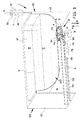
- FIG. 1 shows a bath 1 comprising a safety system according to an exemplary embodiment of the invention.
- the bath 1 with the safety system according to the invention can be used for accommodating a person who is not self-reliant, e.g. a person that cannot keep himself from drowning or a person that is not able to assess or act on the temperature of the water contained in the bath 1 in case of an unsafe temperature.
- the bath 1 comprises a bottom 11 and a circumferential wall 12 standing up from the bottom 11.
- the bottom 11 and the wall 12 define a bath volume 10 for holding water M.
- the bottom 11 and the wall 12 are supported at a distance from the ground by a bath casing 13.
- the casing 13 can also hide the plumbing and the part of the safety system which is arranged underneath the bath 1.
- the bath 1 is provided with a single bath outlet 14 at the bottom 11.
- the safety system comprises a mixing unit 93 which is arranged between the mixed water conduit 92 and a set of hot and cold water conduits 94, 95 which are typically available in a sanitary environment.
- the mixing unit 93 comprises various compartments (not shown) in which mixing valves 96, 97 and a block valve 98 are arranged.
- the mixing unit 93 comprises a first valve 96 arranged in the input line 94 for hot water and a second valve 97 arranged in the input line 95 for cold water, wherein the input line 94 for hot water and the input line 95 for cold water are combined at a position downstream from said first and second valves 96, 97 to form a supply line 92', wherein the flow sensor 75 is arranged in said supply line 92'.
- the mixing unit 93 will also include shuttle valves 99, 99' for selecting either the mixed water conduit 92 of the bath 1 or a secondary mixed water conduit (not shown) leading to the shower head.
- the safety system comprises a user interface 70 arranged within reach of the person accommodated in the bath 1 or within reach of a nurse monitoring the person accommodated in the bath 1.
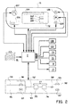
- the user interface 70 is provided with an internal controller 7 which receives signals from various sensors or detection units of the safety system and which sends control signals to the various components of the safety system, for example to the actuator 8 which will be explained in more detail below, and the mixing unit 93.
- the user interface 70 is provided with a control panel 71 and a display 72 for respectively inputting and displaying parameters associated with or derived from the sensor signals received from the safety system.
- the control panel may be provided with a manual input buttons 105 for inputting data to the controller 7, such as desired temperature of the water 101, desired height of the water level 102 and weight or volume of the person 100.
- data is preprogrammed and cannot be changed or inputted without gaining access to the system via a password and/or key, for example a magnetic key 103.
- the input buttons 105 are used to select the name of the person who would like to take a bath from a list of preprogrammed persons, which list also comprises the preprogrammed temperature of the water 101, height of the water level 102 and weight or volume of the person 100.
- the person in the bath can however start the working of the bath by pushing the start button 106, can activate the shower (if present) by pushing the shower button 107 and/or in case of emergency push the alarm button 108.
- the safety system comprises a detection unit 77 which is arranged in the mixing unit 93.
- the detection unit 77 comprises a flow meter or flow sensor 75 which is arranged in the flow of water being supplied to the bath 1 for measuring said flow of water, prior to it entering the bath volume 10.
- the flow sensor 75 can for example be located upstream of the supply outlet 61 of the supply unit 6 as shown in more detail in figures 5A , 5B and 5C , preferably in one of the compartments of the mixing unit 93.
- the flow sensor 75 sends a signal indicative of the measured flow to the controller 7, wherein the controller 7 is arranged for determining the total amount of water being supplied to the bath volume 10 over a period of time based on the received signal.
- the controller 7 can then calculate the theoretical water level W based on a given volume and shape of the bath volume 10. When a predetermined water level W is theoretically reached, the controller 7 takes action to prevent the water level W from rising further, e.g. by activating the block valve 98 for terminating the supply of water to the bath volume 10 or, in case of emergency, by discharging the water M already in the bath volume 10.
- the controller can be connected to the actuator 8 for controlling the discharge unit 2.
- the controller 7 can be programmed to derive and subtract at least part of a volume of the person from the bath volume 10 to obtain a value for the remaining volume of the bath to be filled with water M.
- the detection unit 7 additionally comprises a water level sensor 73.
- the water level sensor 73 comprises a pressure sensor arranged in or near the bottom 11 of the bath 1.
- the pressure sensor is arranged inside a part of the discharge unit 2 which is constantly in fluid connection with the interior of the bath 1.
- the position of the water surface W in the bath can be difficult to accurately determine, because the position of the water surface W can be inconsistent due to movements of the person accommodated in the bath 1.
- movements of the person accommodated in the bath can also provide variations in the signal from the pressure sensor 73, measuring the hydrostatic pressure in or near the bottom 11 of the bath 1 provides a more reliable parameter for determining and controlling the actual water level W.
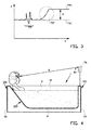
- FIG. 3 An example of the hydrostatic pressure P as measured by the pressure sensor 73 as a function of time t is shown in figure 3 .
- Pressure variations 73' due to movements of the person in the bath 1 are usually characterized by their relatively short time period and/or a substantially random character.
- Pressure variations 73" due to a total submergence of the person in the bath 1 is usually characterized by a substantial increase in the hydrostatic pressure during a longer time period.
- the controller 7 is arranged to distinguish between these modes of variations of the hydrostatic pressure, and to activate an alarm unit 15 when an increase of the hydrostatic pressure is measured which can be attributed to a submergence of the person, for example such as the variation 73" in figure 3 .
- the level sensor 73 which is arranged for detecting the actual water level in the bath 1, sends a signal indicative of the detected actual water level to the controller 7.
- the controller 7 is arranged, upon receipt of a signal from the level sensor 73, to compare the actual water level with the theoretical water level as calculated from the input from the flow sensor 75, preferably taking the volume of the person in the bath 1 into account, and preferably taking into account that at least the head and preferably a shoulder portion of the person is not submerged in the water.
- the combination of the measurements of both a flow sensor 75 and a level sensor 73 can provide increased safety, for example as a failsafe when one of the sensors malfunctions or by having the controller detect a discrepancy between the two sensors.
- the controller 7 is arranged for activating said alarm unit 15 when the actual water level AWL is higher than the theoretical water level TWL, and the difference ⁇ between the actual water level AWL and the theoretical water level TWL is larger than a predetermined level difference.
- the actual water level AWL is higher than the theoretical water level TWL, the person in the bath is submerged more than desired or even fully submerged.
- controller 7 is arranged for terminating the supply of water to the bath volume 10 and/or discharging the water M already in the bath volume 10 either based on a signal from the flow sensor 75 or the water level sensor 73.
- the safety system comprises a person detection unit 81.
- the person detection unit 81 is arranged in the user interface 70.
- the person detection unit 81 may alternatively be arranged separately at a side of the bath 1.
- the person detection unit 81 comprises a distance measuring unit which arranged at a side of the bath and above the bath 1.
- the distance measuring unit 81 is arranged for measuring a distance d between the position of the distance measuring unit 81 at the side of the bath 1 and a part of a person in the bath, which part is above the water level W.
- the person detection unit 81 are arranged for sending signals indicative of the measured distance d to the controller 7.
- the bath 1 shown in the examples is an elongated bath having two longitudinal sides and two transverse sides, wherein the measuring unit 81 is arranged on a first transverse side 121 of the bath 1.
- the bath 1 is arranged to provide a seating accommodation 123 at or near the second side 122 of the bath 1.
- the outlet or discharge opening 14 of the bath 1 is arranged in the bottom wall 11, at or near the first side 121 of the bath as shown in figure 1 .
- the distance measuring unit 81 is arranged above the surface of the water W in the bath 1 and measures the distance d along a line of sight which extends over the surface of the water, as schematically shown in figure 4 .
- the measured distance d is substantially equal or larger than a distance between the first side 121 and the second side 122, there is substantially no part of the person above the surface W of the water, thus the person in the bath is substantially submerged or even fully submerged.
- the alarm unit 15 is activated by the controller 7.
- the controller 7 is arranged for activating said alarm unit 15 when the measured distance d is larger than a distance between the first side 121 of the bath 1 and the part of the person which is in the line of sight, at least when the person is sitting in the bath 1 with his or her back abutting against the inner wall of the bath at the second side 122 of the bath.
- distance measuring comprises an optical distance measuring sensor, preferably using Infra-Red light.
- a person detection system 81 and a water level control system comprising the flow sensor 75 and controller 7, and detection system, comprising the pressure sensor 73, yields a double acting safety system, which reduces the changes of failure of the safety system and which provides an increased safety for the person accommodated in said bath 1, in particular an increased safety against drowning.
- the mixing unit 93 is provided with a first temperature sensor 76 which is arranged for measuring the temperature of the water at or after mixing, yet prior to entering the bath 1.
- the first temperature sensor 76 is part of the safety system.
- the safety system comprises a second temperature sensor 74 for directly measuring the temperature of the water M in the bath 1.
- the second temperature sensor 74 is arranged inside a part of the discharge unit 2 which is constantly in fluid connection with the interior of the bath 1.
- Both sensors 73, 74 are arranged for sending signals indicative of the measured temperatures to the controller 7, wherein, when one of the measured temperatures reaches a predetermined upper value, the controller 7 is arranged for terminating the supply of mixed water to the bath 1, activating the valves 96, 97 for adjusting the mixing ratio of the hot, and cold water, discharging the water already in the bath and/or activating the alarm unit 15.
- the combination of both a first temperature sensor 76 and a second temperature sensor 74 can provide increased safety, for example as a failsafe when one of the sensors malfunctions or by having the controller detect a discrepancy between the two sensors.
- the safety system comprises a discharge unit 2 for draining or discharging water M from the bath 1, a supply unit 6 for supplying water M to the bath 1 and a detection unit 7 for detecting various parameters of the water M in the bath 1.
- the discharge unit 2, the supply unit 6 and the detection unit 7 can be applied to the bath individually or in combination, as will be elucidated below.
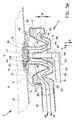
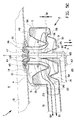
- FIG 2A shows the discharge unit 2 in more detail.
- the discharge unit 2 comprises a housing 20 with a discharge inlet 21, a discharge outlet 23 and a trap channel 22 which connects the discharge inlet 21 to the discharge outlet 23.
- the housing 20 is arranged underneath the bottom 11 of the bath 1.
- the housing 20 has a substantially annular shape from which only the discharge outlet 23 extends radially.
- the annular shape defines a center axis S of the housing 20.
- the discharge inlet 21 and the trap channel 22 are arranged concentrically about the center axis C and - due to the annular shape of the housing 20 - define a central passage 27 in the housing 20 at the center axis S.
- the discharge inlet 21 is connected to or arranged in fluid communication with the bath volume 10 via the bath outlet 14 in the bottom 11 of the bath 1.
- the discharge outlet 23 is connected to or arranged in fluid communication with an external waste water discharge conduit 91 which is typically available in a sanitary environment.
- the discharge outlet 23 extends under a substantially right angle with respect to the discharge inlet 21, to allow for horizontal connection to the waste water discharge conduit 91 and vertical connection to the bath outlet 14.
- the waste water discharge conduit 91 is made of a flexible material or has an adapter piece that forms a flexible connecting with the discharge outlet 23. Such flexibility allows for vertical movement of the discharge unit 2 with respect to the horizontal waste water discharge conduit 91.
- the trap channel 22 is of the siphon-type, having a first U-shaped bend 25 for trapping water.
- the trapped water can form a water seal or a water lock between the discharge inlet 21 and the discharge outlet 23, thereby preventing stench from the sewer from venting into the bath volume 11.
- the trap channel 22 is provided with a second, inverted U-shaped bend 26 which, together with the first bend 25 forms an S-shaped series of bends 25, 26.
- the second bend 26 allows for the discharge outlet 23 to be arranged below or at the level of the first bend 25.
- the discharge outlet 23 is arranged substantially flush with the underside of the housing 20.
- the housing 20 comprises a bottom section 3 and a top section 4.
- the terminology 'bottom', 'top', 'upper' and 'lower' refers to the mutual orientation of interrelated components with respect to the vertical or gravitational direction.
- the bottom section 3 is arranged at the side of the housing 20 facing away from the bottom 11 of the bath 1, while the top section 4 is arranged at the side of the housing 20 facing towards the bottom 11 of the bath 1.
- the top section 4 is fixedly attached to the bath 4.
- the bottom section 3 and the top section 4 are interconnected via an intermediate section 5.
- the bottom section 3, the top section 4 and the intermediate section 5 are integrally formed by blow molding an elastomeric, thermoplastic material such as rubber into the required hollow shape.
- the bottom section 3 comprises a bottom wall 30 which forms the lower boundary for the housing 20.
- the bottom wall 30 is provided with a lower barrier 31 extending upwards towards the top section 4 at the radially outer side of the first bend 25.
- the lower barrier 31 defines an overflow level for the water trapped in the first bend 25.
- the bottom wall 30 merges at a radial position of the annular housing 20 into the discharge outlet 23.
- the top section comprises a top wall 40 which forms the upper boundary for the housing 20.
- the top wall 40 is provided with an upper barrier 41 extending downwards towards the bottom section 3 between the discharge inlet 21 and the lower barrier 31.
- the lowest point of the upper barrier 41 defines a clip or clip level in the first bend 25.
- the upper barrier 41 extends into the first bend 25 and defines a clip level that is past or underneath the overflow level of the lower barrier 31.
- the water M has to flow underneath the clip level before reaching the other end of the first bend 25.
- the overlap distance H1 between the overflow level and the clip level defines the strength of the water lock.
- the discharge unit 2 is provided with a fitting element 45, preferably in the form of a grating, which is arranged to fit and seal the discharge inlet 21 in the bath outlet 14 in the bottom 11 of the bath 1.
- the fitting element 45 comprises a plurality of discharge openings 46 which are evenly distributed about the center axis C, directly above and in fluid communication with the discharge inlet 21.
- the fitting element 45 is further provided with a central supply opening 47 which, when combined with the supply unit 6, functions as an integrated bath inlet within the bath outlet 14 of the bath 1.
- the intermediate section 5 can be formed by any suitable connection that can be contracted and extended, or collapsed and expanded, while maintaining the watertight seal between the bottom section 3 and the top section 4.
- the intermediate section 5 comprises a connecting wall 50 which forms a continuous watertight connection between the bottom section 3 and the top section 4.
- the connecting wall 50 comprises a plurality of flexible folds or corrugations 51 which form a collapsible and expandable connection, a contractible and extendable connection, or a foldable and unfoldable connection between the bottom section 3 and the top section 4.
- the intermediate section 5 facilitates the translating movement of the bottom section 3 with respect to the top section 4 in a substantially vertical, upward first direction A and a substantially vertical downward second direction B, parallel to the center axis C.
- the bottom section 3 can be moved between a first position as shown in figure 2A , a second position as shown in figure 2B and optionally an extreme third position as shown in figure 2C .
- the safety system is provided with an actuator 8, for example in the form of a linear drive, which is operationally coupled to the housing 20, preferably directly to the bottom section 3, to move the bottom section 3 with respect to the top section 4 in the first direction A or the section direction B.
- an actuator 8 for example in the form of a linear drive, which is operationally coupled to the housing 20, preferably directly to the bottom section 3, to move the bottom section 3 with respect to the top section 4 in the first direction A or the section direction B.
- the supply unit 6 is provided with a housing 60, a supply outlet 61 at one end of the housing 60, a supply inlet 63 at an opposite side of the housing 60 and a supply channel 62 formed in the housing 60.
- the supply channel 62 connects the supply inlet 63 to the supply outlet 61.
- the supply outlet 61 is connected to or arranged in fluid communication with the bath volume 10.
- the supply inlet 63 is connected to or arranged in fluid communication with a mixed water conduit 92 from which clean water, which is mixed from hot and cold water to a predetermined temperature, is provided.
- mixed water conduit 92 is made of a flexible material or has an adapter piece that forms a flexible connecting with the supply inlet 63. Such flexibility allows for vertical movement of the supply unit 6 with respect to the horizontal mixed water conduit 92.
- the supply outlet 61 extends through the central passage 27 in the housing 20 of the discharge unit 2, where, at the upper end of the passage 27, the supply outlet 61 is arranged in fluid communication with the supply opening 47 in the center of the fitting element 45.
- the supply unit 6 is provided with a stopper 65 at the supply outlet 61.
- the stopper 65 is arranged to engage, come in abutment with or cooperate with the supply opening 47 of the fitting element 45 such that the supply outlet 61 of the supply unit 63 can be selectively closed or opened.
- the stopper 65 is attached to the supply outlet 61 via an extendable part, for example a telescopic section 64, such that the supply outlet 61 can be moved further downwards after the stopper 65 has engaged with the fitting element 45.
- the supply inlet 63 extends under a substantially right angle with respect to the supply outlet 61, to allow for horizontal connection to the mixed water conduit 92 and vertical connection to the fitting element 47.
- the supply unit 6 is operationally coupled to the discharge unit 2, such that a movement of the bottom section 3 with respect to the top section 4 also controls or moves the stopper 65 at the supply outlet 61.
- the supply unit 6 is mechanically coupled to the discharge unit 2, for example at the center passage 27.
- FIG 2A the situation is shown wherein the bottom section 3 has been moved by the actuator 8 of figure 1 into the first position.
- the trap channel 22 of the housing 20 provides a continuous fluid communication between the discharge inlet 21 and the discharge outlet 23.
- water M in the bath 1 is allowed to enter the discharge unit 2 via discharge openings 46 in the fitting element 45 and the annular discharge inlet 21. Due to the annular arrangement of the discharge inlet 21, the capacity of the discharge inlet 21 can be significantly increased, as the water can enter the discharge inlet 21 at any point around its circumference.
- the water M subsequently flows through the trap channel 22 and exits the housing 20 through the discharge outlet 23.
- the flow of discharging water is indicated schematically with two arrows D1 and D2.
- FIG 2B the situation is shown wherein the bottom section 3 has been moved by the actuator 8 of figure 1 into the second position.
- the corrugations 51 in the wall 51 have been contracted, collapsed or folded with respect to their original state as shown in figure 2A , such that the height of the wall 51, and thus the distance between the bottom section 3 and the top section 4 is reduced.
- the bottom wall 30 of the bottom section 3 has approached the top wall 40 of the top section 4 and is in abutment with the top wall 40 at the upper barrier 41.
- the abutment between the bottom section 3 and the top section 4 forms a water stop or a substantially watertight seal D in the trap channel 22 between the discharge inlet 21 and the discharge outlet 23. Due to the annular shape of the housing 20, the formed seal D extends annularly about the center axis C. The formed seal D prevents water M from flowing out of the bath 1. Thus, in this situation, the bath 1 can be filled with water M.
- FIG 2C the situation is shown wherein the bottom section 3 has been moved by the actuator 8 of figure 1 from the second position as shown in figure 2B into the extreme third position.
- the corrugations 51 in the wall 51 have extended, expanded or unfolded past their normal state as shown in figure 2A .
- the height of the wall 51, and thus the distance between the bottom section 3 and the top section 4 has been maximized.
- the clip level defined by the lowest point of the upper barrier 41 does no longer extend past or underneath the overflow level defined by the highest point of the lower barrier 31, such that the original overlap height H1 as shown in figure 2A is inverted into a clearance height H2.
- the clearance height H2 between the clip level and the overflow level temporarily terminates or suspends the water lock of the trap channel 22 and increases the flow capacity of the trap channel 22.
- the water M can immediately flow from the discharge inlet 21 to the discharge outlet 23, as indicated with discharge flow arrows D1 and D2, without having to overcome the siphon effect of the trap channel 22.
- the third position of the bottom section 3 allows for rapid or accelerated discharge of the water M from the bath 1.
- the supply unit 6 is mechanically coupled to the discharge unit 2 so as to move in unison with the discharge unit 2.
- the supply unit 6 is moved up and down over the same distance.
- the stopper 65 When the bottom section 3 is in the first position, as shown in figure 2A , the stopper 65, in cooperation with the supply opening 47 in the fitting element 45, closes the supply outlet 61 of the supply unit 6. Mixed water, supplied through the mixed water conduit 92 cannot enter the bath 1.
- the stopper 65 When the bottom section 3 is moved into the second position, as shown in figure 2B , the stopper 65 will be moved upwards together with the bottom section 3, until it is clear of the supply opening 47 in the fitting element 45. Now the supply outlet 61 of the supply unit 6 is opened and mixed water from the mixed water conduit 92 is allowed to flow via the supply outlet 61 into the bath 1, as indicated with supply flow arrows S.
- a valve for example the closing valve in the mixing unit 93, can interrupt the supply flow S, such that the filling of the bath 1 is interrupted and the current water level is maintained.
- the stopper 65 When the bottom section 3 is moved from the second position into the third position, as shown in figure 2C , the stopper 65 is moved downwards correspondingly.
- the stopper 65 engages with the fitting element 45 and closes the supply outlet 61 as the bottom section 3 moves through the first position as shown in figure 2A .
- the telescopic section 64 starts extending the connection between the stopper 65 and the supply outlet 61 such that the supply unit 6 can be moved further downwards together with the bottom section 3 of the discharge unit 2. Meanwhile, the stopper 65 remains engaged with the fitting element 45 and as such closes the supply outlet 61 of the supply unit 6.
- the aforementioned safety system is provided with a pump in the housing 20 of the discharge unit 2 or downstream thereof for accelerating the discharge of the water M from the bath volume 10.
- the invention relates to a safety system for a bath and a bath comprising said safety system.
- the safety system comprising a detection unit with a controller and a flow sensor which is arranged for measuring a flow of water being supplied to the bath.
- the sensor is arranged for sending a signal indicative of the measured flow to the controller
- the controller is arranged for determining the total amount of water being supplied to the bath and for calculating the theoretical water level in the bath.
- the detection unit additionally comprises a level sensor which is arranged for sending a signal indicative of the detected actual water level to the controller.
- the controller is arranged for comparing the actual water level with the theoretical water level.
- the safety system comprises a discharge unit for discharging water from the bath, wherein the discharge unit is provided with a discharge inlet, a discharge outlet and a housing, wherein the housing comprises a bottom section and a top section, wherein the bottom section is moveable with respect to the top section between a first position and a second position, wherein, in the first position, the bottom section and the top section together form a trap channel between the discharge inlet and the discharge outlet, wherein, in the second position, the bottom section is in abutment with the top section such that, at the abutment between the bottom section and the top section, a substantially watertight seal is formed in the trap channel between the discharge inlet and the discharge outlet.
Landscapes
- Health & Medical Sciences (AREA)
- Public Health (AREA)
- Engineering & Computer Science (AREA)
- Epidemiology (AREA)
- General Health & Medical Sciences (AREA)
- Environmental & Geological Engineering (AREA)
- Life Sciences & Earth Sciences (AREA)
- Hydrology & Water Resources (AREA)
- Water Supply & Treatment (AREA)
- Control For Baths (AREA)
- Devices For Medical Bathing And Washing (AREA)
Applications Claiming Priority (1)
| Application Number | Priority Date | Filing Date | Title |
|---|---|---|---|
| NL2010184 | 2013-01-25 |
Publications (2)
| Publication Number | Publication Date |
|---|---|
| EP2759643A2 true EP2759643A2 (fr) | 2014-07-30 |
| EP2759643A3 EP2759643A3 (fr) | 2014-08-27 |
Family
ID=49998139
Family Applications (1)
| Application Number | Title | Priority Date | Filing Date |
|---|---|---|---|
| EP14152479.3A Withdrawn EP2759643A3 (fr) | 2013-01-25 | 2014-01-24 | Système de sécurité pour bain |
Country Status (1)
| Country | Link |
|---|---|
| EP (1) | EP2759643A3 (fr) |
Cited By (9)
| Publication number | Priority date | Publication date | Assignee | Title |
|---|---|---|---|---|
| EP2918739A1 (fr) * | 2014-03-11 | 2015-09-16 | Viega GmbH & Co. KG | Dispositif d'actionnement automatique d'une bonde d'évacuation dans sur un bassin sanitaire, en particulier une baignoire, et baignoire dotée d'un tel dispositif |
| JP2018164692A (ja) * | 2017-03-28 | 2018-10-25 | 東京瓦斯株式会社 | 排水システム及び浴室システム |
| EP3418457A1 (fr) * | 2017-06-20 | 2018-12-26 | Grohe AG | Système de surveillance permettant de surveiller un niveau d'eau dans un élément sanitaire ainsi qu'un élément sanitaire |
| JP2019002643A (ja) * | 2017-06-16 | 2019-01-10 | 株式会社コロナ | 風呂給湯装置 |
| JP2020052800A (ja) * | 2018-09-27 | 2020-04-02 | Necエンベデッドプロダクツ株式会社 | 異常検知装置、異常検知方法、プログラム |
| JP2020076524A (ja) * | 2018-11-07 | 2020-05-21 | 株式会社コロナ | 風呂給湯装置 |
| JP2022055066A (ja) * | 2020-09-28 | 2022-04-07 | 株式会社ノーリツ | 浴槽洗浄装置 |
| JP2022067720A (ja) * | 2020-10-21 | 2022-05-09 | 大阪瓦斯株式会社 | 浴室システム |
| JP2023077503A (ja) * | 2021-11-25 | 2023-06-06 | 積水ホームテクノ株式会社 | 浴槽システム及び入槽判定方法 |
Family Cites Families (5)
| Publication number | Priority date | Publication date | Assignee | Title |
|---|---|---|---|---|
| GB2242758B (en) * | 1989-11-03 | 1993-08-18 | Sure Right Webb Ltd | Water flow control system |
| JPH0755251A (ja) * | 1993-08-11 | 1995-03-03 | Takagi Ind Co Ltd | 浴槽の溺水防止装置 |
| JP2002288760A (ja) * | 2001-03-23 | 2002-10-04 | Osaka Gas Co Ltd | 入浴中の溺水検出装置 |
| PT1249544E (pt) * | 2001-04-14 | 2003-09-30 | Kaldewei Franz Gmbh & Co | Dispositivo para o comando do enchimento de tina de uma banheira sanitaria |
| US20050251906A1 (en) * | 2004-05-17 | 2005-11-17 | Brad Scott | Automatic bathtub filing control system |
-
2014
- 2014-01-24 EP EP14152479.3A patent/EP2759643A3/fr not_active Withdrawn
Non-Patent Citations (1)
| Title |
|---|
| None |
Cited By (12)
| Publication number | Priority date | Publication date | Assignee | Title |
|---|---|---|---|---|
| EP2918739A1 (fr) * | 2014-03-11 | 2015-09-16 | Viega GmbH & Co. KG | Dispositif d'actionnement automatique d'une bonde d'évacuation dans sur un bassin sanitaire, en particulier une baignoire, et baignoire dotée d'un tel dispositif |
| JP2018164692A (ja) * | 2017-03-28 | 2018-10-25 | 東京瓦斯株式会社 | 排水システム及び浴室システム |
| JP2019002643A (ja) * | 2017-06-16 | 2019-01-10 | 株式会社コロナ | 風呂給湯装置 |
| EP3418457A1 (fr) * | 2017-06-20 | 2018-12-26 | Grohe AG | Système de surveillance permettant de surveiller un niveau d'eau dans un élément sanitaire ainsi qu'un élément sanitaire |
| CN109099987A (zh) * | 2017-06-20 | 2018-12-28 | 高仪股份公司 | 用于监测卫生元件中的水位的监测系统以及卫生元件 |
| US10877493B2 (en) | 2017-06-20 | 2020-12-29 | Grohe Ag | Monitoring system for monitoring a water level in a plumbing element, and a plumbing element |
| JP2020052800A (ja) * | 2018-09-27 | 2020-04-02 | Necエンベデッドプロダクツ株式会社 | 異常検知装置、異常検知方法、プログラム |
| JP2020076524A (ja) * | 2018-11-07 | 2020-05-21 | 株式会社コロナ | 風呂給湯装置 |
| JP2022055066A (ja) * | 2020-09-28 | 2022-04-07 | 株式会社ノーリツ | 浴槽洗浄装置 |
| JP7478948B2 (ja) | 2020-09-28 | 2024-05-08 | 株式会社ノーリツ | 浴槽洗浄装置 |
| JP2022067720A (ja) * | 2020-10-21 | 2022-05-09 | 大阪瓦斯株式会社 | 浴室システム |
| JP2023077503A (ja) * | 2021-11-25 | 2023-06-06 | 積水ホームテクノ株式会社 | 浴槽システム及び入槽判定方法 |
Also Published As
| Publication number | Publication date |
|---|---|
| EP2759643A3 (fr) | 2014-08-27 |
Similar Documents
| Publication | Publication Date | Title |
|---|---|---|
| EP2759643A2 (fr) | Système de sécurité pour bain | |
| KR101252136B1 (ko) | 지하수 유출량 및 함양량을 연속 계측할 수 있는 유입출 측정장치 | |
| CN101495932B (zh) | 自动浴缸填充器 | |
| JP2016132985A (ja) | 洗浄弁アセンブリ及び洗浄弁アセンブリを含むトイレ洗浄システム | |
| JP2014169784A (ja) | バキュームブレーカ、腰掛便器自動吐水システムおよび電子腰掛便器 | |
| US6961966B2 (en) | Toilet overflow prevention device | |
| US9756988B2 (en) | Gravity shower | |
| EP2312067B1 (fr) | Robinet reglable pour remplissage de citernes | |
| US8375481B1 (en) | Shower water recycling system for toilet flushing | |
| JP2020002560A (ja) | 定水位弁装置 | |
| EP2037051B1 (fr) | Dispositif de limitation de remplissage de type dissimulé pour installations sanitaires et installation sanitaire l'utilisant | |
| US10314440B2 (en) | Bathtub with door and drain | |
| EP1754838A2 (fr) | Système de drainage avec entrée latérale | |
| WO2015027330A1 (fr) | Système intérieur de collecte d'eau de pluie | |
| AU2022204308A1 (en) | Accumulator assembly | |
| CN114356001A (zh) | 足浴控制方法及足浴器 | |
| US20250281002A1 (en) | Bathtub and/or shower tray | |
| US10370836B2 (en) | Toilet flushing system installed in a toilet reservoir | |
| US20240318414A1 (en) | Systems and methods of filling and draining plumbing fixtures | |
| KR102637443B1 (ko) | 유아 세면 장치 | |
| TWI542763B (zh) | Flushing and flushing water tanks | |
| JP2020041754A (ja) | 給湯システム | |
| JP7663871B2 (ja) | 排水栓装置 | |
| IT201900000643A1 (it) | Sanitario a scomparsa con "washlet" | |
| JP3019649B2 (ja) | 不凍給水栓 |
Legal Events
| Date | Code | Title | Description |
|---|---|---|---|
| PUAL | Search report despatched |
Free format text: ORIGINAL CODE: 0009013 |
|
| PUAI | Public reference made under article 153(3) epc to a published international application that has entered the european phase |
Free format text: ORIGINAL CODE: 0009012 |
|
| 17P | Request for examination filed |
Effective date: 20140124 |
|
| AK | Designated contracting states |
Kind code of ref document: A2 Designated state(s): AL AT BE BG CH CY CZ DE DK EE ES FI FR GB GR HR HU IE IS IT LI LT LU LV MC MK MT NL NO PL PT RO RS SE SI SK SM TR |
|
| AX | Request for extension of the european patent |
Extension state: BA ME |
|
| AK | Designated contracting states |
Kind code of ref document: A3 Designated state(s): AL AT BE BG CH CY CZ DE DK EE ES FI FR GB GR HR HU IE IS IT LI LT LU LV MC MK MT NL NO PL PT RO RS SE SI SK SM TR |
|
| AX | Request for extension of the european patent |
Extension state: BA ME |
|
| RIC1 | Information provided on ipc code assigned before grant |
Ipc: E03C 1/242 20060101AFI20140721BHEP Ipc: A47K 3/00 20060101ALI20140721BHEP |
|
| STAA | Information on the status of an ep patent application or granted ep patent |
Free format text: STATUS: THE APPLICATION IS DEEMED TO BE WITHDRAWN |
|
| 18D | Application deemed to be withdrawn |
Effective date: 20150228 |