EP2759772B1 - Chambres de combustion avec trous d'effusion de forme complexe - Google Patents
Chambres de combustion avec trous d'effusion de forme complexe Download PDFInfo
- Publication number
- EP2759772B1 EP2759772B1 EP14150504.0A EP14150504A EP2759772B1 EP 2759772 B1 EP2759772 B1 EP 2759772B1 EP 14150504 A EP14150504 A EP 14150504A EP 2759772 B1 EP2759772 B1 EP 2759772B1
- Authority
- EP
- European Patent Office
- Prior art keywords
- liner
- combustor
- effusion cooling
- segment
- inlet
- Prior art date
- Legal status (The legal status is an assumption and is not a legal conclusion. Google has not performed a legal analysis and makes no representation as to the accuracy of the status listed.)
- Active
Links
Images




Classifications
-
- F—MECHANICAL ENGINEERING; LIGHTING; HEATING; WEAPONS; BLASTING
- F23—COMBUSTION APPARATUS; COMBUSTION PROCESSES
- F23R—GENERATING COMBUSTION PRODUCTS OF HIGH PRESSURE OR HIGH VELOCITY, e.g. GAS-TURBINE COMBUSTION CHAMBERS
- F23R3/00—Continuous combustion chambers using liquid or gaseous fuel
- F23R3/002—Wall structures
-
- F—MECHANICAL ENGINEERING; LIGHTING; HEATING; WEAPONS; BLASTING
- F23—COMBUSTION APPARATUS; COMBUSTION PROCESSES
- F23R—GENERATING COMBUSTION PRODUCTS OF HIGH PRESSURE OR HIGH VELOCITY, e.g. GAS-TURBINE COMBUSTION CHAMBERS
- F23R3/00—Continuous combustion chambers using liquid or gaseous fuel
- F23R3/02—Continuous combustion chambers using liquid or gaseous fuel characterised by the air-flow or gas-flow configuration
- F23R3/04—Air inlet arrangements
- F23R3/06—Arrangement of apertures along the flame tube
-
- F—MECHANICAL ENGINEERING; LIGHTING; HEATING; WEAPONS; BLASTING
- F23—COMBUSTION APPARATUS; COMBUSTION PROCESSES
- F23R—GENERATING COMBUSTION PRODUCTS OF HIGH PRESSURE OR HIGH VELOCITY, e.g. GAS-TURBINE COMBUSTION CHAMBERS
- F23R3/00—Continuous combustion chambers using liquid or gaseous fuel
- F23R3/02—Continuous combustion chambers using liquid or gaseous fuel characterised by the air-flow or gas-flow configuration
- F23R3/16—Continuous combustion chambers using liquid or gaseous fuel characterised by the air-flow or gas-flow configuration with devices inside the flame tube or the combustion chamber to influence the air or gas flow
-
- F—MECHANICAL ENGINEERING; LIGHTING; HEATING; WEAPONS; BLASTING
- F23—COMBUSTION APPARATUS; COMBUSTION PROCESSES
- F23R—GENERATING COMBUSTION PRODUCTS OF HIGH PRESSURE OR HIGH VELOCITY, e.g. GAS-TURBINE COMBUSTION CHAMBERS
- F23R3/00—Continuous combustion chambers using liquid or gaseous fuel
- F23R3/42—Continuous combustion chambers using liquid or gaseous fuel characterised by the arrangement or form of the flame tubes or combustion chambers
- F23R3/50—Combustion chambers comprising an annular flame tube within an annular casing
-
- F—MECHANICAL ENGINEERING; LIGHTING; HEATING; WEAPONS; BLASTING
- F23—COMBUSTION APPARATUS; COMBUSTION PROCESSES
- F23R—GENERATING COMBUSTION PRODUCTS OF HIGH PRESSURE OR HIGH VELOCITY, e.g. GAS-TURBINE COMBUSTION CHAMBERS
- F23R2900/00—Special features of, or arrangements for continuous combustion chambers; Combustion processes therefor
- F23R2900/00018—Manufacturing combustion chamber liners or subparts
-
- F—MECHANICAL ENGINEERING; LIGHTING; HEATING; WEAPONS; BLASTING
- F23—COMBUSTION APPARATUS; COMBUSTION PROCESSES
- F23R—GENERATING COMBUSTION PRODUCTS OF HIGH PRESSURE OR HIGH VELOCITY, e.g. GAS-TURBINE COMBUSTION CHAMBERS
- F23R2900/00—Special features of, or arrangements for continuous combustion chambers; Combustion processes therefor
- F23R2900/03041—Effusion cooled combustion chamber walls or domes
-
- F—MECHANICAL ENGINEERING; LIGHTING; HEATING; WEAPONS; BLASTING
- F23—COMBUSTION APPARATUS; COMBUSTION PROCESSES
- F23R—GENERATING COMBUSTION PRODUCTS OF HIGH PRESSURE OR HIGH VELOCITY, e.g. GAS-TURBINE COMBUSTION CHAMBERS
- F23R2900/00—Special features of, or arrangements for continuous combustion chambers; Combustion processes therefor
- F23R2900/03042—Film cooled combustion chamber walls or domes
-
- Y—GENERAL TAGGING OF NEW TECHNOLOGICAL DEVELOPMENTS; GENERAL TAGGING OF CROSS-SECTIONAL TECHNOLOGIES SPANNING OVER SEVERAL SECTIONS OF THE IPC; TECHNICAL SUBJECTS COVERED BY FORMER USPC CROSS-REFERENCE ART COLLECTIONS [XRACs] AND DIGESTS
- Y02—TECHNOLOGIES OR APPLICATIONS FOR MITIGATION OR ADAPTATION AGAINST CLIMATE CHANGE
- Y02T—CLIMATE CHANGE MITIGATION TECHNOLOGIES RELATED TO TRANSPORTATION
- Y02T50/00—Aeronautics or air transport
- Y02T50/60—Efficient propulsion technologies, e.g. for aircraft
-
- Y—GENERAL TAGGING OF NEW TECHNOLOGICAL DEVELOPMENTS; GENERAL TAGGING OF CROSS-SECTIONAL TECHNOLOGIES SPANNING OVER SEVERAL SECTIONS OF THE IPC; TECHNICAL SUBJECTS COVERED BY FORMER USPC CROSS-REFERENCE ART COLLECTIONS [XRACs] AND DIGESTS
- Y10—TECHNICAL SUBJECTS COVERED BY FORMER USPC
- Y10T—TECHNICAL SUBJECTS COVERED BY FORMER US CLASSIFICATION
- Y10T29/00—Metal working
- Y10T29/49—Method of mechanical manufacture
- Y10T29/49229—Prime mover or fluid pump making
- Y10T29/49231—I.C. [internal combustion] engine making
Definitions
- the following discussion generally relates to gas turbine engine combustors, and more particularly, to combustors with complex shaped effusion holes.
- Gas turbine engines are generally used in a wide range of applications, such as aircraft engines and auxiliary power units.
- air is compressed in a compressor, and mixed with fuel and ignited in a combustor to generate hot combustion gases, which flow downstream into a turbine section for energy extraction.
- the combustor typically includes radially spaced apart inner and outer liners.
- the inner and outer liners generally define an annular combustion chamber between the compressor and the turbine.
- EP2455665 and US2010/0119377 are examples of gas turbines which incorporate effusion holes within the gas turbine components to aid cooling.
- the present invention provides a combustor as defined in claim 1.
- the combustor may include the features of any one or more of dependent claims 2 to 3.
- Embodiments described herein provide a combustor having single-walled or dual-walled liners with effusion and/or impingement cooling holes having complex shapes.
- the effusion cooling holes have a non-linear line of sight arrangement.
- the effusion cooling holes are at least partially formed by a tube portion extending outward from the hot side of the combustion liner.
- effusion cooling holes may have multiple outlets.
- Such effusion cooling holes may be formed by additive manufacturing techniques.
- FIG. 1 is a simplified, cross-sectional view of a gas turbine engine 100 according to an embodiment.
- the engine 100 may be disposed in an engine case 110 and may include a fan section 120, a compressor section 130, a combustor section 140, a turbine section 150, and an exhaust section 160.
- the fan section 120 may include a fan 122, which draws in and accelerates air. A fraction of the accelerated air exhausted from the fan 122 is directed through a bypass section 170 to provide a forward thrust. The remaining fraction of air exhausted from the fan 122 is directed into the compressor section 130.
- the compressor section 130 may include a series of compressors 132 that raise the pressure of the air directed from the fan 122. The compressors 132 then direct the compressed air into the combustor section 140. In the combustor section 140, the high pressure air is mixed with fuel and combusted. The combusted air is then directed into the turbine section 150.
- the turbine section 150 may include a series of turbines 152, which may be disposed in axial flow series.
- the combusted air from the combustor section 140 expands through and rotates the turbines 152 prior to being exhausted through a propulsion nozzle 162 disposed in the exhaust section 160.
- the turbines 152 rotate to drive equipment in the engine 100 via concentrically disposed shafts or spools.
- the turbines 152 may drive the compressors 132 via one or more rotors 154.
- FIG. 1 depicts one exemplary configuration. Other embodiments may have alternate arrangements, such as to provide mechanical power or compressed air instead of thrust.
- FIG. 2 is a more detailed cross-sectional view of the combustor section 140 of FIG. 1 .
- the combustor section 140 of FIG. 2 is an annular combustor section 140, although aspects of exemplary embodiments described herein may also be useful in can combustors, can-annular combustors, and other types of combustors.
- exemplary embodiments may find beneficial uses in many industries, including aerospace and particularly in high performance aircraft, as well as automotive, marine and power generation.
- the combustor section 140 includes a radially inner case 202 and a radially outer case 204 concentrically arranged with respect to the inner case 202.
- the inner and outer cases 202, 204 circumscribe the axially extending engine centerline 200 to define an annular pressure vessel 206.
- the combustor section 140 also includes a combustor 208 residing within the annular pressure vessel 206.
- the combustor 208 is defined by an outer liner 210 and an inner liner 212 that is circumscribed by the outer liner 210 to define an annular combustion chamber 214.
- the liners 210, 212 cooperate with cases 202, 204 to define respective outer and inner air plenums 216, 218.
- the combustor 208 includes a front end assembly 220 comprising a dome assembly 222, fuel injectors 224, and fuel injector guides 226.
- One fuel injector 224 and one fuel injector guide 226 are shown in the partial cross-sectional view of FIG. 2 .
- the combustor 208 includes a total of sixteen circumferentially distributed fuel injectors 224, but it will be appreciated that the combustor 208 could be implemented with more or less than this number of fuel injectors 224.
- Each fuel injector 224 introduces a swirling, intimately blended fuel-air mixture that supports combustion in the combustion chamber 214.
- the depicted combustor 208 is a rich burn, quick quench, lean burn (RQL) combustor, although further exemplary embodiments may include other types of combustors.
- RQL lean burn
- a portion of the pressurized air enters a rich burn zone RB of the combustion chamber 214 by way of passages in the front end assembly 220.
- This air is referred to as primary combustion air because it intermixes with a stoichiometrically excessive quantity of fuel introduced through the fuel injectors 224 to support initial combustion in the rich burn zone RB.
- the rich stoichiometry of the fuel-air mixture in the rich burn zone RB produces a relatively cool, oxygen-deprived flame, thus preventing excessive NOx formation and guarding against blowout of the combustion flame during any abrupt reduction in engine power.
- the combustion products from the rich burn zone RB which include unburned fuel, then enter a quench zone Q.
- Jets 252 flow from the plenum 216 into the quench zone Q through air admission (or quench) holes 250 in the outer liner 210.
- jets 272 flow from the plenum 218 into the quench zone Q through air admission (or quench) holes 270 in the inner liner 212. Additional holes with similar features and arrangements may be provided in both the outer and inner liners 210, 212 to provide additional quench jets to the combustion chamber 214.
- the quench air jets 252 272 rapidly mix the combustion products from a stoichiometrically rich state at the forward edge of the quench zone Q to a stoichiometrically lean state at, or immediately downstream of, the aft edge of the quench zone Q to support further combustion and release additional energy from the fuel in order to avoid excessive NOx generation. Finally, the combustion products from the quench zone Q enter a lean burn zone LB where the combustion process concludes.
- the engine components are subject to extremely high temperatures resulting from high velocity hot gases ducted from the combustor section 140 ( FIG. 2 ). If unaddressed, the extreme heat may affect the useful life of the component and/or impact the maximum operating temperature of the engine. As such, cooling techniques and/or mechanism may be provided to maintain temperature at an acceptable level. Such cooling may include effusion cooling techniques, as described in greater detail below.
- FIG. 3 is a partial outer plan view of a liner 300 of a combustor, such as the combustor 208 of FIG. 2 , in accordance with an exemplary embodiment.
- the liner 300 may represent any portion of the outer or inner liner 210, 212 of the combustor 208 of FIG. 2 .
- the liner 300 may include a number of effusion cooling holes 310. Additional details about the effusion cooling holes 310 will be provided with reference to FIGS. 4 and 5.
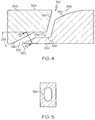
- FIG. 4 is a cross-sectional view of a different effusion cooling hole 310 of the liner 300 of FIG. 3 not in accordance with an embodiment
- FIG. 5 is a cross-sectional view of the effusion cooling hole 310 of FIG. 4 through line 5-5.
- FIGS. 3-5 will be discussed together.
- the effusion cooling holes 310 are relatively small, closely spaced holes serving to direct a flow of cooling air through the liner 300.
- the effusion cooling holes 310 are typically angled at, for example, 0°-45° to the surface of the liner 300, and may be oriented to discharge at various angles relative to the bulk combustor gas flow, such that a film of cooling air forms on the inner surface of the liner 300, e.g., the surface facing the combustion chamber.
- an effusion cooling hole 310 with an angle of 0° may be considered tangent to the downstream surface.
- the effusion cooling hole 310 extends from a first (or cold) side 302 of the liner 300, through the liner 300, to a second (or hot) side 304 of the liner 300. Accordingly, the effusion cooling hole 310 may be considered to have an upstream portion 320 with an inlet 322, an intermediate portion 340, and a downstream portion 330 with an outlet 332.
- the portions 320, 330, 340, including the inlet 322 and outlet 332, may have any suitable configuration or shape. Moreover, additional portions or segments may be provided as necessary or desired.
- the upstream portion 320 is generally straight at a first angle 324 relative to the first side 302 of the liner 300.
- the upstream portion 320 has an oval cross-sectional shape, as best shown by FIG. 5 .
- the upstream portion 320 may have any suitable shape, including circular or non-regular.
- the inlet 322 may have any suitable inlet angle, including for example 5° or less.
- the intermediate portion 340 extends within the interior of the liner 300 between the upstream portion 320 and the downstream portion 330.
- the intermediate portion 340 extends parallel to the cold and hot sides (or surfaces) 302, 304.
- the intermediate portion 340 may be also be parallel to the surfaces that are curved, e.g., the intermediate portion 340 may match the curvature of the liner 300.
- the intermediate portion 340 may have any suitable configuration and shape.
- the downstream portion 330 is generally straight at a second angle 334.
- the second angle 334 may be different than the first angle 324.
- the downstream portion 330 of each cooling hole 310 is at least partially defined by or otherwise fluidly coupled to a trench 350.
- the trench 350 includes a base surface that transitions from the downstream portion 300 to the outlet 332.
- the trench 350 is configured to provide improved film cooling at the surface of the liner 300 by providing a relatively small exit angle.
- the trench 350 enables the cooling air to remain attached to the liner 300 for a longer period of time and minimizes mixing of the cooling air and mainstream gas flow, thereby resulting in a more effective film.
- each cooling hole 310 is associated with a single trench 350, e.g., each trench 350 is only in fluid communication with a single hole and not other cooling holes or trenches.
- the trench 350 is arranged at the exit of the cooling hole 220 and is typically very close to the outer surface 304 of the liner 300.
- the trench 350 may have any suitable shape or configuration, including a predetermined length, width, and depth.
- the trench 350 is depicted convex, although the trench may also be straight, concave, or portions with various shapes.
- the trench 350 transitions into the outlet 332, as best shown in the plan view of FIG. 3 .
- the outlet 332 has a shape of truncated pyramid with rounded edges or a "fan" shape.
- any suitable shape may be provided, including bean shapes, triad shapes, dumbbell shapes, triangular shapes, oval shapes, and/or non-regular shapes.
- the effusion cooling hole 310 may be considered to have a non-linear line of sight. In other words, there is no virtual, single straight line segment that may be extended between the inlet 322 and outlet 332, given the areas of the inlet 322 and outlet 332, and the diameters, shapes, and angles of the respective portions 320, 330.
- the inlet 322 is may be offset or non-parallel to the outlet 332. Additional details about forming the effusion cooling hole 310 are provided below. Moreover, other types of cooling holes may be provides, as will now be described.
- FIGS. 6 and 7 An embodiment of effusion cooling holes 610 according to the invention is depicted by FIGS. 6 and 7 .
- Such effusion cooling holes 610 may be incorporated into a combustor, such as the combustor 208 of FIG. 2 .
- Each effusion cooling hole 610 includes an inlet 612 on a cold side 602, an outlet 622 on a hot side 604, and a main (or tube) portion 630 extending between the inlet 612 and outlet 622.
- the tube portion 630 includes a number of segments 632, 634, 636, 638.
- the tube portion 630 is formed by an outer structure 650 that extends or protrudes from the cold side 602 of the liner 600.
- the outer structure 650 extends radially outward from the cold side 602, e.g., the outer structure 650 is not in the same plane as the cold side 602..
- the first segment 632 extends from the outlet 622 to the second segment 634.
- the first segment 632 is formed by the outer structure 650 and the cold side 604 of the liner 600.
- the inlet 612 and the first segment 632 are, completely exterior to the plane defined by the cold side 602 of the liner 600.
- the inlet 612 is completely non-planar with the cold side 602, and in the depicted embodiment, the inlet 612 is perpendicular to the plane defined by the cold side 602.
- the first segment 632 has a bell-mouth structure. In other words, the area of the first segment 632 increases towards the inlet 612. As a result of this configuration, the first segment 632 functions as a scoop to direct air into the effusion cooling hole 610.
- the second segment 634 extends from the first segment 632 to the third segment 636.
- the second segment 634 is formed by the outer structure 650 and the cold side 604 of the liner 600.
- the inlet 612 and the second segment 634 are, in effect, completely exterior to the plane defined by the cold side 602 of the liner 600.
- the second segment 634 has a generally constant area along the length of the second segment 634.
- the third segment 636 extends from the second segment 634 to the fourth segment 638.
- the third segment 636 is formed by the outer structure 650 and an interior portion 606 of the liner 600.
- the interior portion 606 of the liner 600 corresponds to the liner portion between the plane formed by the hot side 602 and the plane formed by the cold side 604.
- the third segment 636 has a generally constant area along the length of the third segment 636.
- the fourth segment 638 extends from the third segment 636 to the outlet 622.
- the fourth segment 638 is formed completely within the interior portion 606 of the liner 600.
- the fourth segment 638 has a generally constant area along the length of the fourth segment 638, although the area may also be varied.
- the outlet 622 may have a protruding or scoop structure similar to the structure 650 as necessary or desired for advantageous cooling flow placement.
- the effusion cooling hole 650 has a relatively long length-to-diameter ratio.
- the length-to-diameter ratio may be for example, between 2-50. In other embodiments, the length-to-diameter ratio may be, for example between 10-50 or between 25-50..
- Such a ratio may enhance cooling in a number of ways. For example, the extended length enables placement of cooling air in areas that may have otherwise been difficult to reach. Additionally, the extended length may enable enhanced conduction cooling of the liners.
- tube portion 630 has been described with respect to four segments 632, 634, 636, 638, one of more of the segments 632, 634, 636, 638 may be omitted and/or modified.
- One of more of the segments 632, 634, 636, 638 may function as a metering segment to provide the desired amount of cooling air through the effusion cooling hole 610. Additionally, one or more additional segments may be added to provide any suitable configuration or arrangement.
- the effusion cooling hole 610 has a non-linear line of sight. In other words, there is no virtual straight line that may be extended between the inlet 612 and outlet 622, given the areas of the inlet 612 and outlet 622, and the diameters, shapes, and angles of the respective segments 632, 634, 636, 638.
- FIGS. 8-10 A further exemplary embodiment of effusion cooling holes 810 is depicted by FIGS. 8-10 .
- FIG. 8 is a partial outer isometric view of a liner 800 of the combustor section in accordance with an alternate exemplary embodiment
- FIG. 9 is a partial inner isometric view of the liner 800 of FIG. 8 in accordance with the alternate exemplary embodiment.
- FIG. 10 is a cross-sectional view generally through line 10-10 of FIG. 8 and generally along a longitudinal axis of the cooling hole 810.
- the effusion cooling hole 810 may include an inlet 812, dual outlets 822, 824, and a main (or tube) portion 830 extending between the inlet 812 and dual outlets 822, 824.
- the inlet 812 is best shown in FIG. 8 .
- the dual outlets 822, 824 are best shown by FIG. 9 , and FIG. 10 shows the general shape of the effusion cooling hole 810.
- the effusion cooling hole 810 may include an upstream segment 830 and first and second downstream segments 842, 844. Each of the downstream segments 842, 844 are fluidly coupled to the upstream segment 830.
- the upstream and downstream segments 830, 842, 844 may be formed by an exterior tube portion 850 extending from the plane defined by the cold side 820 of the liner 800.
- the effusion cooling hole 810 may be considered to have a non-linear line of sight. In other words, there is no virtual straight line that may be extended between the inlet 812 and outlets 822, 824, given the areas of the inlet 812 and outlets 822, 824, and the diameters, shapes, and angles of the respective segments 830, 842, 844.
- the effusion cooling hole 810 has been described with respect to three segments 830, 842, 844, one or more additional segments may be added to provide any suitable configuration or arrangement.
- the effusion cooling hole 810 may include one or more additional inlets and outlets. As such, any number of inlets and outlets may be formed within the liner in a fluidly coupled arrangement.
- FIG. 11 is a partial outer isometric view of a liner 1100 of the combustor section in accordance with an alternate exemplary embodiment
- FIG. 12 is a partial inner isometric view of the liner 1100 of FIG. 11 in accordance with the alternate exemplary embodiment.
- the effusion cooling hole 1110 may include an inlet 1112 on a cold side 1102, an outlet 1122 on a hot side 1104, and a main (or tube) portion 1130 extending between the inlet 1112 and outlet 1122.
- a portion of the inlet 1112 and tube portion 1130 is formed by an exterior tube portion 1150 extending from the plane defined by the cold side 1102 of the liner 1100.
- the effusion cooling hole 1110 may be considered to have a longitudinal axis that is curved relative to an axial direction and/or local streamlines in a plane corresponding to the cold side 1102.
- the effusion cooling hole 1110 enables the cooling air flow to be redirected to any desirable angle.
- the cooling air flow through the effusion cooling hole 1110 may be redirected 90°, 180°, or 270° from to the angle at the inlet 1112 relative to the plane of the cold side 1102.
- Such holes 1110 may be referred to as cambered holes that change the tangential component of the air as it passes through the hole.
- the effusion cooling hole 1110 may be considered to have a non-linear line of sight. In other words, there is no virtual straight line that may be extended between the inlet 1112 and outlet 1122, given the areas of the inlet 1112 and outlet 1122, 1124, and the diameters, shapes, and angles of the portions 1130.
- FIG. 13 is a flowchart of a method 1300 for manufacturing a combustor component, such as the liners with effusion cooling holes discussed above.
- a model such as a design model, of the combustor component may be defined in any suitable manner.
- the model may be designed with computer aided design (CAD) software and include 3D numeric coordinates of the entire configuration of the combustor component including both external and internal surfaces.
- the model may include a number of successive 2D cross-sectional slices that together form the 3D component.
- an intermediate combustor component article is formed according to the model of step 1310.
- the intermediate combustor component article may include the effusion cooling holes discussed above.
- the unfinished combustor component at intermediate steps in the process, such as step 1320 may be referred to as an intermediate combustor component article (or generally, "intermediate article").
- the intermediate combustor component article may be formed using a rapid prototyping or additive layer manufacturing process. Although additive layer manufacturing processes are described in greater detail below, the component article may be forged or cast in step 1320, for example, with a single-crystal structure. Other manufacturing methods may be employed to fabricate the component article.
- additive layer manufacturing processes include: micro-pen deposition in which liquid media is dispensed with precision at the pen tip and then cured; selective laser sintering in which a laser is used to sinter a powder media in precisely controlled locations; laser wire deposition in which a wire feedstock is melted by a laser and then deposited and solidified in precise locations to build the product; electron beam melting; laser engineered net shaping; and direct metal deposition.
- additive manufacturing techniques may provide flexibility in free-form fabrication without geometric constraints, fast material processing time, and innovative joining techniques.
- Direct metal laser fusion (DMLF) may be used to produce the first portion of step 1320.
- DMLF is a commercially available laser-based rapid prototyping and tooling process by which complex parts may be directly produced by precision melting and solidification of metal powder into successive layers of larger structures, each layer corresponding to a cross-sectional layer of the 3D component.
- DMLF may include direct metal laser sintering (DMLS).
- Step 1320 is performed with DMLF techniques to form the of the intermediate combustor component article.
- FIG. 14 is a schematic view of a DMLF system 1400 for manufacturing the one or more portions of the intermediate combustor component article.
- the system 1400 includes a fabrication device 1410, a powder delivery device 1430, a scanner 1440, and a laser 1460 that function to manufacture the respective portion of an intermediate combustor component article 1450 with build material 1470.
- the fabrication device 1410 includes a build container 1412 with a fabrication support 1414 on which the intermediate combustor component article 1450 is formed and supported.
- the fabrication support 1414 is movable within the build container 1412 in a vertical direction and is adjusted in such a way to define a working plane 1416.
- the delivery device 1430 includes a powder chamber 1432 with a delivery support 1434 that supports the build material 1470 and is also movable in the vertical direction.
- the delivery device 1430 further includes a roller or wiper 1436 that transfers build material 1470 from the delivery device 1430 to the fabrication device 1410.
- a base block 1445 may be installed on the fabrication support 1414.
- the fabrication support 1414 is lowered and the delivery support 1434 is raised.
- the roller or wiper 1436 scrapes or otherwise pushes a portion of the build material 1470 from the delivery device 1430 to form the working plane1 416 in the fabrication device 1410.
- the laser 1460 emits a laser beam 1462, which is directed by the scanner 1440 onto the build material 1470 in the working plane 1416 to selectively fuse the build material 1470 into a cross-sectional layer of the intermediate combustor component article 1450 according to the design.
- the speed, position, and other operating parameters of the laser beam 1462 are controlled to selectively fuse the powder of the build material 1470 into larger structures by rapidly melting the powder particles that may melt or diffuse into the solid structure below, and subsequently, cool and resolidify.
- each layer of build material 1470 will include unfused and fused build material 1470 that respectively corresponds to the cross-sectional passages and walls that form the intermediate combustor component article 1450.
- the laser beam 1462 is relatively low power to selectively fuse the individual layer of build material 1470.
- the laser beam 1462 may have a power of approximately 50 to 500 Watts, although any suitable power may be provided.
- the fabrication support 1414 Upon completion of a respective layer, the fabrication support 1414 is lowered and the delivery support 1434 is raised. Typically, the fabrication support 1414, and thus the intermediate combustor component article 1450, does not move in a horizontal plane during this step.
- the roller or wiper 1436 again pushes a portion of the build material 1470 from the delivery device 1430 to form an additional layer of build material 1470 on the working plane 1416 of the fabrication device 1410.
- the laser beam 1462 is movably supported relative to the intermediate combustor component article 1450 and is again controlled to selectively form another cross-sectional layer. As such, the intermediate combustor component article 1450 is positioned in a bed of build material 1470 as the successive layers are formed such that the unfused and fused material supports subsequent layers. This process is continued according to the modeled design as successive cross-sectional layers are formed into the completed desired portion.
- the delivery of build material 1470 and movement of the intermediate combustor component article 1450 in the vertical direction are relatively constant and only the movement of the laser beam 1462 must be selectively controlled to provide a simpler and more precise implementation.
- the localized fusing of the build material 1470 enables more precise placement of fused material to reduce or eliminate the occurrence of over-deposition of material and excessive energy or heat, which may otherwise result in cracking or distortion.
- the unused and unfused build material 1470 may be reused, thereby further reducing scrap.
- the build material 1470 may be formed by any suitable powder, including powdered metals, such as a stainless steel powder, and alloys and super alloy materials, such as nickel-based or cobalt superalloys.
- the build material 1470 is a high temperature nickel base super alloy such as IN625, MAR-M-247, SC180, CMSX486, HON-4A, and Alloy 10.
- IN718 or IN738 or other suitable alloys may be employed.
- the powder build material 1470 may be selected for enhanced strength, durability, and useful life, particularly at high temperatures, although as described below, the powder build material 1470 may also be selected based on the intended function of the area being formed. Each successive layer may be, for example, between 10 ⁇ m and 200 ⁇ m, although the thickness may be selected based on any number of parameters. As noted above, the build material 1470 may be selected based on the desired properties of the portion respectively being formed.
- the first portion is removed from additive manufacturing system (e.g., from the DMLF system 1400).
- the first portion formed in step 1320 may undergo treatments.
- the portion treatments of step 1330 refer to intermediate processing treatments that may be suitable for the first portion but that may be unsuitable for portions formed in subsequent steps, e.g., because of the temperature or other processing requirements of the desired treatment.
- portion treatments may include, for example, solutioning, aging, annealing, quenching, peening, polishing, hot isostatic pressing (HIP), or coatings.
- Portion treatments of step 1330 may comprise stress relief, solutioning, high temperature aging, peening, HIP, and polishing.
- An alternate material or fabrication method may be employed which may result in different step 1330 portion treatments for optimizing the component.
- a post-laser fusion process of step 1330 is a HIP process in which an encapsulation layer is applied to the intermediate combustor component article and pressure and heat are applied to remove or reduce any porosity and cracks internal to or on the surface.
- the encapsulation layer functions to effectively convert any surface porosity and cracks into internal porosity and cracks, and after the application of pressure and heat, removes or reduces the porosity and cracks.
- Such encapsulation layers may be subsequently removed or maintained to function as an oxidation protection layer.
- the encapsulation layer may be a metal or alloy that is compatible with the substrate and may be applied by a plating or coating process, as described below.
- the HIP process may be performed at a processing temperature in a range of about 1000° C to about 1300° C and may be performed at a pressure in a range of about 1 ksi to about 25 ksi for a time period of about 1 to about 10 hours.
- the HIP processing temperature, pressure, and time may be smaller or larger to form a compacted solid having negligible porosity.
- the intermediate combustor component article may be machined to the final specifications.
- the intermediate combustor component article may undergo optional coating operations such as wear resistance, oxidation, environmental, and thermal barrier coatings.
- the combustor component may be tested and installed in a combustor section of a gas turbine engine, as shown in FIG. 1 .
- the method 1300 has been discussed above with reference to the formation of a single combustor article, and thus, a single combustor component. Portions or groups of components (e.g., panels or combustors and/or full combustors) may be manufactured as noted above. Additionally, in method 1300, more than one combustor article may be manufactured simultaneously. Unless otherwise noted, method 1300 proceeds as discussed above. In method 1300, the combustor articles are formed on a common base block to provide a common orientation and a known point of reference and formed as discussed above. Successive layers can be formed for the group of combustor articles simultaneously according to a common module or design.
- the powdered metal may be deposited across a single working plane and one or more lasers may selectively fuse the layers of each combustor article, either sequentially or simultaneously.
- the combustor articles may then be lowered together for the formation of the next layer. Simultaneous fabrication of a number of components may minimize cost and variability of the manufacturing process.
- effusion cooling holes are: Although the embodiments discussed above generally refer to single-walled combustors, the effusion cooling holes discussed above may additionally be incorporated into double-walled combustors, including a double-walled combustor that utilizes impingement effusion cooling.
- a cold wall that may form part of a combustor liner e.g., inner liner or outer liner
- the impingement cooling holes are typically 90° to the surface of the cold wall, although other arrangements are contemplated.
- the hot wall includes a number of effusion cooling holes, such as the effusion cooling holes discussed above, that serve to direct a flow of cooling air through the hot wall such that a film of cooling air forms on the hot wall.
- effusion cooling holes discussed above may be incorporated into other combustor components, including nozzles, diffusers, dome structures, and case structures. In general, the embodiments described above may be combined to satisfy particular requirements.
- embodiments discussed above provide combustors with improved effusion cooling holes.
- improved cooling may enhance durability and performance of the combustor components and the overall engine.
- the cooling holes enable cooling air to be placed as necessary or desired, including in positions remote from the inlet and/or that better align with the greater flow field.
- the combustor components may be fabricated with additive manufacturing techniques, including DMLF. Such techniques reduce costs and cycle time in the engine design, particularly in the iterative environment of engine design. Additionally, these techniques may produce combustor components capable of withstanding higher temperatures and stresses, thereby leading to further improvements in engine performance. Embodiments are applicable to both commercial and military gas turbine engines and auxiliary power units, including industrial applications such as electricity generation, naval propulsion, pumping sets for gas and oil transmission, aircraft and/or spacecraft propulsion, automobile engines, and/or stationary power plants.
Landscapes
- Engineering & Computer Science (AREA)
- Chemical & Material Sciences (AREA)
- Combustion & Propulsion (AREA)
- Mechanical Engineering (AREA)
- General Engineering & Computer Science (AREA)
- Turbine Rotor Nozzle Sealing (AREA)
Claims (3)
- Appareil de combustion (208) pour un moteur à turbine (100), comprenant :une première chemise (210, 212, 300, 600, 800, 1100) ayant un premier côté et un deuxième côté ; etune deuxième chemise (210, 212) ayant un premier côté et un deuxième côté, le deuxième côté de la deuxième chemise (210, 212) formant une chambre de combustion (214) avec le deuxième côté de la première chemise (210, 212, 300, 600, 800, 1100), la chambre de combustion (214) étant configurée pour recevoir un mélange air-combustible en vue de sa combustion dans celle-ci ;la première chemise (210, 212, 300, 600, 800, 1100) définissant une pluralité de trous de refroidissement d'effusion (310, 610, 810, 1110) configurés pour former un film d'air de refroidissement sur le deuxième côté de la première chemise (210, 212, 300, 600, 800, 1100), la pluralité de trous de refroidissement d'effusion (310, 610, 810, 1110) comportant un premier trou de refroidissement d'effusion (310, 610, 810, 1110) s'étendant depuis le premier côté jusqu'au deuxième côté avec une ligne de vision non linéaire,caractérisé en ce quele premier trou de refroidissement d'effusion (610) comporte une entrée (612) et un premier segment (632) s'étendant depuis l'entrée (612), le premier segment (632) et l'entrée (612) étant positionnés à l'extérieur d'un plan de chemise défini par le premier côté (604) de la chemise et étant formé par une structure extérieure (650) et le premier côté (604) de la chemise dans le plan de la chemise,le premier trou de refroidissement d'effusion (610) comportant en outre un deuxième segment (634) s'étendant depuis le premier segment (632), le deuxième segment étant formé par le premier côté (604) de la chemise et la structure extérieure (650), le deuxième segment ayant une superficie constante le long de sa longueur.
- Appareil de combustion (208) selon la revendication 1, dans lequel le premier trou de refroidissement d'effusion (610) comporte une entrée en forme de pavillon (632).
- Appareil de combustion (208) selon la revendication 1, dans lequel le premier trou de refroidissement d'effusion (810) comporte une première entrée (812) et des première et deuxième sorties (822, 824) accouplées fluidiquement à la première entrée (812).
Applications Claiming Priority (1)
| Application Number | Priority Date | Filing Date | Title |
|---|---|---|---|
| US13/747,938 US9765968B2 (en) | 2013-01-23 | 2013-01-23 | Combustors with complex shaped effusion holes |
Publications (2)
| Publication Number | Publication Date |
|---|---|
| EP2759772A1 EP2759772A1 (fr) | 2014-07-30 |
| EP2759772B1 true EP2759772B1 (fr) | 2016-04-27 |
Family
ID=49920175
Family Applications (1)
| Application Number | Title | Priority Date | Filing Date |
|---|---|---|---|
| EP14150504.0A Active EP2759772B1 (fr) | 2013-01-23 | 2014-01-08 | Chambres de combustion avec trous d'effusion de forme complexe |
Country Status (2)
| Country | Link |
|---|---|
| US (1) | US9765968B2 (fr) |
| EP (1) | EP2759772B1 (fr) |
Families Citing this family (42)
| Publication number | Priority date | Publication date | Assignee | Title |
|---|---|---|---|---|
| US9650900B2 (en) | 2012-05-07 | 2017-05-16 | Honeywell International Inc. | Gas turbine engine components with film cooling holes having cylindrical to multi-lobe configurations |
| US10113433B2 (en) | 2012-10-04 | 2018-10-30 | Honeywell International Inc. | Gas turbine engine components with lateral and forward sweep film cooling holes |
| US9228747B2 (en) * | 2013-03-12 | 2016-01-05 | Pratt & Whitney Canada Corp. | Combustor for gas turbine engine |
| US20160025010A1 (en) * | 2013-03-26 | 2016-01-28 | United Technologies Corporation | Turbine engine and turbine engine component with cooling pedestals |
| EP3097301B1 (fr) * | 2014-01-24 | 2018-05-02 | United Technologies Corporation | Volet divergent |
| DE102014213302A1 (de) * | 2014-07-09 | 2016-01-14 | Rolls-Royce Deutschland Ltd & Co Kg | Brennkammer einer Gasturbine mit verschraubtem Brennkammerkopf |
| GB201417429D0 (en) * | 2014-10-02 | 2014-11-19 | Rolls Royce Plc | A cooled component |
| GB201417587D0 (en) | 2014-10-06 | 2014-11-19 | Rolls Royce Plc | A cooked component |
| US20160230993A1 (en) * | 2015-02-10 | 2016-08-11 | United Technologies Corporation | Combustor liner effusion cooling holes |
| US20160245094A1 (en) * | 2015-02-24 | 2016-08-25 | General Electric Company | Engine component |
| FR3036139B1 (fr) * | 2015-05-12 | 2019-12-13 | Safran Aircraft Engines | Turbomachine comportant un melangeur a lobes avec ecopes. |
| FR3037107B1 (fr) * | 2015-06-03 | 2019-11-15 | Safran Aircraft Engines | Paroi annulaire de chambre de combustion a refroidissement optimise |
| EP3109550B1 (fr) | 2015-06-19 | 2019-09-04 | Rolls-Royce Corporation | Air de refroidissement refroidi de turbine circulant par un agencement tubulaire |
| CA2933884A1 (fr) * | 2015-06-30 | 2016-12-30 | Rolls-Royce Corporation | Tuile de combustor |
| US10871075B2 (en) | 2015-10-27 | 2020-12-22 | Pratt & Whitney Canada Corp. | Cooling passages in a turbine component |
| US10533749B2 (en) * | 2015-10-27 | 2020-01-14 | Pratt & Whitney Cananda Corp. | Effusion cooling holes |
| DE102015225505A1 (de) * | 2015-12-16 | 2017-06-22 | Rolls-Royce Deutschland Ltd & Co Kg | Wand eines mittels Kühlluft zu kühlenden Bauteils, insbesondere einer Gasturbinenbrennkammerwand |
| US10100668B2 (en) | 2016-02-24 | 2018-10-16 | General Electric Company | System and method of fabricating and repairing a gas turbine component |
| US11021965B2 (en) | 2016-05-19 | 2021-06-01 | Honeywell International Inc. | Engine components with cooling holes having tailored metering and diffuser portions |
| KR101766449B1 (ko) * | 2016-06-16 | 2017-08-08 | 두산중공업 주식회사 | 공기유도 캡 및 이를 구비하는 연소 덕트 |
| US11015529B2 (en) | 2016-12-23 | 2021-05-25 | General Electric Company | Feature based cooling using in wall contoured cooling passage |
| US10731562B2 (en) * | 2017-07-17 | 2020-08-04 | Raytheon Technologies Corporation | Combustor panel standoffs with cooling holes |
| DE102017216595A1 (de) | 2017-09-19 | 2019-03-21 | Rolls-Royce Deutschland Ltd & Co Kg | Triebwerksbauteil mit mindestens einem Kühlloch |
| US11988145B2 (en) * | 2018-01-12 | 2024-05-21 | Rtx Corporation | Apparatus and method for mitigating airflow separation around engine combustor |
| US10989408B2 (en) * | 2018-09-13 | 2021-04-27 | Raytheon Technologies Corporation | Additive integral combustor expansion spring |
| US11402096B2 (en) * | 2018-11-05 | 2022-08-02 | Rolls-Royce Corporation | Combustor dome via additive layer manufacturing |
| US11085641B2 (en) * | 2018-11-27 | 2021-08-10 | Honeywell International Inc. | Plug resistant effusion holes for gas turbine engine |
| US11306659B2 (en) | 2019-05-28 | 2022-04-19 | Honeywell International Inc. | Plug resistant effusion holes for gas turbine engine |
| US11486578B2 (en) | 2020-05-26 | 2022-11-01 | Raytheon Technologies Corporation | Multi-walled structure for a gas turbine engine |
| US11371701B1 (en) | 2021-02-03 | 2022-06-28 | General Electric Company | Combustor for a gas turbine engine |
| US11549437B2 (en) | 2021-02-18 | 2023-01-10 | Honeywell International Inc. | Combustor for gas turbine engine and method of manufacture |
| US11674686B2 (en) * | 2021-05-11 | 2023-06-13 | Honeywell International Inc. | Coating occlusion resistant effusion cooling holes for gas turbine engine |
| US12085283B2 (en) | 2021-06-07 | 2024-09-10 | General Electric Company | Combustor for a gas turbine engine |
| US11885495B2 (en) | 2021-06-07 | 2024-01-30 | General Electric Company | Combustor for a gas turbine engine including a liner having a looped feature |
| US11959643B2 (en) | 2021-06-07 | 2024-04-16 | General Electric Company | Combustor for a gas turbine engine |
| US12146660B2 (en) | 2021-06-07 | 2024-11-19 | General Electric Company | Combustor for a gas turbine engine |
| US12152777B2 (en) | 2021-06-07 | 2024-11-26 | General Electric Company | Combustor for a gas turbine engine |
| US11774098B2 (en) | 2021-06-07 | 2023-10-03 | General Electric Company | Combustor for a gas turbine engine |
| CN114384198B (zh) * | 2022-02-16 | 2023-03-31 | 南京上元分析仪器有限公司 | 一种建材单体制品燃烧试验设备 |
| CN116792778A (zh) * | 2022-03-21 | 2023-09-22 | 通用电气公司 | 涡轮发动机燃烧器和燃烧器衬套 |
| US12222104B2 (en) | 2022-03-21 | 2025-02-11 | General Electric Company | Turbine engine combustor and combustor liner |
| US20260098638A1 (en) * | 2024-10-04 | 2026-04-09 | Pratt & Whitney Canada Corp. | Combustor liner v-band with directed air flow |
Family Cites Families (13)
| Publication number | Priority date | Publication date | Assignee | Title |
|---|---|---|---|---|
| US6627019B2 (en) | 2000-12-18 | 2003-09-30 | David C. Jarmon | Process for making ceramic matrix composite parts with cooling channels |
| GB2373319B (en) | 2001-03-12 | 2005-03-30 | Rolls Royce Plc | Combustion apparatus |
| US7464554B2 (en) | 2004-09-09 | 2008-12-16 | United Technologies Corporation | Gas turbine combustor heat shield panel or exhaust panel including a cooling device |
| JP4752841B2 (ja) | 2005-11-01 | 2011-08-17 | 株式会社Ihi | タービン部品 |
| US8092176B2 (en) | 2008-09-16 | 2012-01-10 | Siemens Energy, Inc. | Turbine airfoil cooling system with curved diffusion film cooling hole |
| US7997865B1 (en) | 2008-09-18 | 2011-08-16 | Florida Turbine Technologies, Inc. | Turbine blade with tip rail cooling and sealing |
| US8057181B1 (en) | 2008-11-07 | 2011-11-15 | Florida Turbine Technologies, Inc. | Multiple expansion film cooling hole for turbine airfoil |
| GB2465337B (en) | 2008-11-12 | 2012-01-11 | Rolls Royce Plc | A cooling arrangement |
| US7997868B1 (en) | 2008-11-18 | 2011-08-16 | Florida Turbine Technologies, Inc. | Film cooling hole for turbine airfoil |
| US9810081B2 (en) | 2010-06-11 | 2017-11-07 | Siemens Energy, Inc. | Cooled conduit for conveying combustion gases |
| CH703657A1 (de) * | 2010-08-27 | 2012-02-29 | Alstom Technology Ltd | Verfahren zum betrieb einer brenneranordnung sowie brenneranordnung zur durchführung des verfahrens. |
| DE102010051638A1 (de) | 2010-11-17 | 2012-05-24 | Rolls-Royce Deutschland Ltd & Co Kg | Gasturbinenbrennkammer mit einer Kühlluftzuführvorrichtung |
| US9416971B2 (en) * | 2012-02-15 | 2016-08-16 | United Technologies Corporation | Multiple diffusing cooling hole |
-
2013
- 2013-01-23 US US13/747,938 patent/US9765968B2/en active Active
-
2014
- 2014-01-08 EP EP14150504.0A patent/EP2759772B1/fr active Active
Also Published As
| Publication number | Publication date |
|---|---|
| US20140338347A1 (en) | 2014-11-20 |
| EP2759772A1 (fr) | 2014-07-30 |
| US9765968B2 (en) | 2017-09-19 |
Similar Documents
| Publication | Publication Date | Title |
|---|---|---|
| EP2759772B1 (fr) | Chambres de combustion avec trous d'effusion de forme complexe | |
| EP2905538B1 (fr) | Chambres de combustion de moteur à turbine à gaz avec refroidissement par impact et effusion et procédés de fabrication desdites chambres | |
| EP3559555B1 (fr) | Élément pour moteur de turbine à gaz comprenant un canal de refroidissement de forme contourée | |
| EP2868973B1 (fr) | Moteurs à turbine à gaz ayant des carénages d'injecteur de carburant avec des nervures intérieures | |
| US8061142B2 (en) | Mixer for a combustor | |
| US9739161B2 (en) | Vaned structure and a method of manufacturing a vaned structure | |
| EP2975351B1 (fr) | Finition de surface par fabrication additive | |
| EP3415718B1 (fr) | Composants de moteur à turbine à gaz comportant des caractéristiques de refroidissement par air et leurs procédés de fabrication associés | |
| EP3511627B1 (fr) | Appareil à buse à combustible remplaçable, système et procédé | |
| US10260749B2 (en) | Combustion chamber wall and a method of manufacturing a combustion chamber wall | |
| EP2636982A2 (fr) | Systèmes d'échange de chaleur tubulaires | |
| US20160033129A1 (en) | Additive manufactured gas turbine engine combustor liner panel | |
| EP3086041B1 (fr) | Écran thermique de brûleur à fabrication additive | |
| US20170198587A1 (en) | Cooled article | |
| EP3176505B1 (fr) | Injecteur de carburantet son procédé de fabrication | |
| US20250244016A1 (en) | Turbomachine having improved mixing tube elements |
Legal Events
| Date | Code | Title | Description |
|---|---|---|---|
| PUAI | Public reference made under article 153(3) epc to a published international application that has entered the european phase |
Free format text: ORIGINAL CODE: 0009012 |
|
| 17P | Request for examination filed |
Effective date: 20140108 |
|
| AK | Designated contracting states |
Kind code of ref document: A1 Designated state(s): AL AT BE BG CH CY CZ DE DK EE ES FI FR GB GR HR HU IE IS IT LI LT LU LV MC MK MT NL NO PL PT RO RS SE SI SK SM TR |
|
| AX | Request for extension of the european patent |
Extension state: BA ME |
|
| REG | Reference to a national code |
Ref country code: DE Ref legal event code: R079 Ref document number: 602014001599 Country of ref document: DE Free format text: PREVIOUS MAIN CLASS: F23R0003060000 Ipc: F23R0003000000 |
|
| GRAP | Despatch of communication of intention to grant a patent |
Free format text: ORIGINAL CODE: EPIDOSNIGR1 |
|
| RAP1 | Party data changed (applicant data changed or rights of an application transferred) |
Owner name: HONEYWELL INTERNATIONAL INC. |
|
| RIC1 | Information provided on ipc code assigned before grant |
Ipc: F23R 3/00 20060101AFI20151130BHEP Ipc: F23R 3/16 20060101ALI20151130BHEP Ipc: F23R 3/50 20060101ALI20151130BHEP Ipc: F23R 3/06 20060101ALI20151130BHEP |
|
| INTG | Intention to grant announced |
Effective date: 20151216 |
|
| GRAS | Grant fee paid |
Free format text: ORIGINAL CODE: EPIDOSNIGR3 |
|
| GRAA | (expected) grant |
Free format text: ORIGINAL CODE: 0009210 |
|
| AK | Designated contracting states |
Kind code of ref document: B1 Designated state(s): AL AT BE BG CH CY CZ DE DK EE ES FI FR GB GR HR HU IE IS IT LI LT LU LV MC MK MT NL NO PL PT RO RS SE SI SK SM TR |
|
| REG | Reference to a national code |
Ref country code: GB Ref legal event code: FG4D |
|
| REG | Reference to a national code |
Ref country code: CH Ref legal event code: EP |
|
| REG | Reference to a national code |
Ref country code: AT Ref legal event code: REF Ref document number: 795244 Country of ref document: AT Kind code of ref document: T Effective date: 20160515 |
|
| REG | Reference to a national code |
Ref country code: IE Ref legal event code: FG4D |
|
| REG | Reference to a national code |
Ref country code: DE Ref legal event code: R096 Ref document number: 602014001599 Country of ref document: DE |
|
| REG | Reference to a national code |
Ref country code: LT Ref legal event code: MG4D |
|
| REG | Reference to a national code |
Ref country code: NL Ref legal event code: MP Effective date: 20160427 |
|
| REG | Reference to a national code |
Ref country code: AT Ref legal event code: MK05 Ref document number: 795244 Country of ref document: AT Kind code of ref document: T Effective date: 20160427 |
|
| PG25 | Lapsed in a contracting state [announced via postgrant information from national office to epo] |
Ref country code: NL Free format text: LAPSE BECAUSE OF FAILURE TO SUBMIT A TRANSLATION OF THE DESCRIPTION OR TO PAY THE FEE WITHIN THE PRESCRIBED TIME-LIMIT Effective date: 20160427 |
|
| PG25 | Lapsed in a contracting state [announced via postgrant information from national office to epo] |
Ref country code: FI Free format text: LAPSE BECAUSE OF FAILURE TO SUBMIT A TRANSLATION OF THE DESCRIPTION OR TO PAY THE FEE WITHIN THE PRESCRIBED TIME-LIMIT Effective date: 20160427 Ref country code: PL Free format text: LAPSE BECAUSE OF FAILURE TO SUBMIT A TRANSLATION OF THE DESCRIPTION OR TO PAY THE FEE WITHIN THE PRESCRIBED TIME-LIMIT Effective date: 20160427 Ref country code: LT Free format text: LAPSE BECAUSE OF FAILURE TO SUBMIT A TRANSLATION OF THE DESCRIPTION OR TO PAY THE FEE WITHIN THE PRESCRIBED TIME-LIMIT Effective date: 20160427 Ref country code: NO Free format text: LAPSE BECAUSE OF FAILURE TO SUBMIT A TRANSLATION OF THE DESCRIPTION OR TO PAY THE FEE WITHIN THE PRESCRIBED TIME-LIMIT Effective date: 20160727 |
|
| PG25 | Lapsed in a contracting state [announced via postgrant information from national office to epo] |
Ref country code: AT Free format text: LAPSE BECAUSE OF FAILURE TO SUBMIT A TRANSLATION OF THE DESCRIPTION OR TO PAY THE FEE WITHIN THE PRESCRIBED TIME-LIMIT Effective date: 20160427 Ref country code: PT Free format text: LAPSE BECAUSE OF FAILURE TO SUBMIT A TRANSLATION OF THE DESCRIPTION OR TO PAY THE FEE WITHIN THE PRESCRIBED TIME-LIMIT Effective date: 20160829 Ref country code: SE Free format text: LAPSE BECAUSE OF FAILURE TO SUBMIT A TRANSLATION OF THE DESCRIPTION OR TO PAY THE FEE WITHIN THE PRESCRIBED TIME-LIMIT Effective date: 20160427 Ref country code: HR Free format text: LAPSE BECAUSE OF FAILURE TO SUBMIT A TRANSLATION OF THE DESCRIPTION OR TO PAY THE FEE WITHIN THE PRESCRIBED TIME-LIMIT Effective date: 20160427 Ref country code: ES Free format text: LAPSE BECAUSE OF FAILURE TO SUBMIT A TRANSLATION OF THE DESCRIPTION OR TO PAY THE FEE WITHIN THE PRESCRIBED TIME-LIMIT Effective date: 20160427 Ref country code: GR Free format text: LAPSE BECAUSE OF FAILURE TO SUBMIT A TRANSLATION OF THE DESCRIPTION OR TO PAY THE FEE WITHIN THE PRESCRIBED TIME-LIMIT Effective date: 20160728 Ref country code: RS Free format text: LAPSE BECAUSE OF FAILURE TO SUBMIT A TRANSLATION OF THE DESCRIPTION OR TO PAY THE FEE WITHIN THE PRESCRIBED TIME-LIMIT Effective date: 20160427 Ref country code: LV Free format text: LAPSE BECAUSE OF FAILURE TO SUBMIT A TRANSLATION OF THE DESCRIPTION OR TO PAY THE FEE WITHIN THE PRESCRIBED TIME-LIMIT Effective date: 20160427 |
|
| PG25 | Lapsed in a contracting state [announced via postgrant information from national office to epo] |
Ref country code: IT Free format text: LAPSE BECAUSE OF FAILURE TO SUBMIT A TRANSLATION OF THE DESCRIPTION OR TO PAY THE FEE WITHIN THE PRESCRIBED TIME-LIMIT Effective date: 20160427 Ref country code: BE Free format text: LAPSE BECAUSE OF FAILURE TO SUBMIT A TRANSLATION OF THE DESCRIPTION OR TO PAY THE FEE WITHIN THE PRESCRIBED TIME-LIMIT Effective date: 20160427 |
|
| REG | Reference to a national code |
Ref country code: DE Ref legal event code: R097 Ref document number: 602014001599 Country of ref document: DE |
|
| PG25 | Lapsed in a contracting state [announced via postgrant information from national office to epo] |
Ref country code: DK Free format text: LAPSE BECAUSE OF FAILURE TO SUBMIT A TRANSLATION OF THE DESCRIPTION OR TO PAY THE FEE WITHIN THE PRESCRIBED TIME-LIMIT Effective date: 20160427 Ref country code: EE Free format text: LAPSE BECAUSE OF FAILURE TO SUBMIT A TRANSLATION OF THE DESCRIPTION OR TO PAY THE FEE WITHIN THE PRESCRIBED TIME-LIMIT Effective date: 20160427 Ref country code: CZ Free format text: LAPSE BECAUSE OF FAILURE TO SUBMIT A TRANSLATION OF THE DESCRIPTION OR TO PAY THE FEE WITHIN THE PRESCRIBED TIME-LIMIT Effective date: 20160427 Ref country code: RO Free format text: LAPSE BECAUSE OF FAILURE TO SUBMIT A TRANSLATION OF THE DESCRIPTION OR TO PAY THE FEE WITHIN THE PRESCRIBED TIME-LIMIT Effective date: 20160427 Ref country code: SK Free format text: LAPSE BECAUSE OF FAILURE TO SUBMIT A TRANSLATION OF THE DESCRIPTION OR TO PAY THE FEE WITHIN THE PRESCRIBED TIME-LIMIT Effective date: 20160427 |
|
| PG25 | Lapsed in a contracting state [announced via postgrant information from national office to epo] |
Ref country code: SM Free format text: LAPSE BECAUSE OF FAILURE TO SUBMIT A TRANSLATION OF THE DESCRIPTION OR TO PAY THE FEE WITHIN THE PRESCRIBED TIME-LIMIT Effective date: 20160427 |
|
| PLBE | No opposition filed within time limit |
Free format text: ORIGINAL CODE: 0009261 |
|
| STAA | Information on the status of an ep patent application or granted ep patent |
Free format text: STATUS: NO OPPOSITION FILED WITHIN TIME LIMIT |
|
| 26N | No opposition filed |
Effective date: 20170130 |
|
| PG25 | Lapsed in a contracting state [announced via postgrant information from national office to epo] |
Ref country code: SI Free format text: LAPSE BECAUSE OF FAILURE TO SUBMIT A TRANSLATION OF THE DESCRIPTION OR TO PAY THE FEE WITHIN THE PRESCRIBED TIME-LIMIT Effective date: 20160427 |
|
| REG | Reference to a national code |
Ref country code: CH Ref legal event code: PL |
|
| PG25 | Lapsed in a contracting state [announced via postgrant information from national office to epo] |
Ref country code: MC Free format text: LAPSE BECAUSE OF FAILURE TO SUBMIT A TRANSLATION OF THE DESCRIPTION OR TO PAY THE FEE WITHIN THE PRESCRIBED TIME-LIMIT Effective date: 20160427 |
|
| REG | Reference to a national code |
Ref country code: FR Ref legal event code: ST Effective date: 20170929 |
|
| PG25 | Lapsed in a contracting state [announced via postgrant information from national office to epo] |
Ref country code: LI Free format text: LAPSE BECAUSE OF NON-PAYMENT OF DUE FEES Effective date: 20170131 Ref country code: CH Free format text: LAPSE BECAUSE OF NON-PAYMENT OF DUE FEES Effective date: 20170131 Ref country code: FR Free format text: LAPSE BECAUSE OF NON-PAYMENT OF DUE FEES Effective date: 20170131 |
|
| REG | Reference to a national code |
Ref country code: IE Ref legal event code: MM4A |
|
| PG25 | Lapsed in a contracting state [announced via postgrant information from national office to epo] |
Ref country code: LU Free format text: LAPSE BECAUSE OF NON-PAYMENT OF DUE FEES Effective date: 20170108 |
|
| PG25 | Lapsed in a contracting state [announced via postgrant information from national office to epo] |
Ref country code: IE Free format text: LAPSE BECAUSE OF NON-PAYMENT OF DUE FEES Effective date: 20170108 |
|
| GBPC | Gb: european patent ceased through non-payment of renewal fee |
Effective date: 20180108 |
|
| PG25 | Lapsed in a contracting state [announced via postgrant information from national office to epo] |
Ref country code: MT Free format text: LAPSE BECAUSE OF NON-PAYMENT OF DUE FEES Effective date: 20170108 |
|
| PG25 | Lapsed in a contracting state [announced via postgrant information from national office to epo] |
Ref country code: AL Free format text: LAPSE BECAUSE OF FAILURE TO SUBMIT A TRANSLATION OF THE DESCRIPTION OR TO PAY THE FEE WITHIN THE PRESCRIBED TIME-LIMIT Effective date: 20160427 |
|
| PG25 | Lapsed in a contracting state [announced via postgrant information from national office to epo] |
Ref country code: GB Free format text: LAPSE BECAUSE OF NON-PAYMENT OF DUE FEES Effective date: 20180108 |
|
| PG25 | Lapsed in a contracting state [announced via postgrant information from national office to epo] |
Ref country code: HU Free format text: LAPSE BECAUSE OF FAILURE TO SUBMIT A TRANSLATION OF THE DESCRIPTION OR TO PAY THE FEE WITHIN THE PRESCRIBED TIME-LIMIT; INVALID AB INITIO Effective date: 20140108 |
|
| PG25 | Lapsed in a contracting state [announced via postgrant information from national office to epo] |
Ref country code: BG Free format text: LAPSE BECAUSE OF FAILURE TO SUBMIT A TRANSLATION OF THE DESCRIPTION OR TO PAY THE FEE WITHIN THE PRESCRIBED TIME-LIMIT Effective date: 20160427 |
|
| PG25 | Lapsed in a contracting state [announced via postgrant information from national office to epo] |
Ref country code: CY Free format text: LAPSE BECAUSE OF NON-PAYMENT OF DUE FEES Effective date: 20160427 |
|
| PG25 | Lapsed in a contracting state [announced via postgrant information from national office to epo] |
Ref country code: MK Free format text: LAPSE BECAUSE OF FAILURE TO SUBMIT A TRANSLATION OF THE DESCRIPTION OR TO PAY THE FEE WITHIN THE PRESCRIBED TIME-LIMIT Effective date: 20160427 |
|
| PG25 | Lapsed in a contracting state [announced via postgrant information from national office to epo] |
Ref country code: TR Free format text: LAPSE BECAUSE OF FAILURE TO SUBMIT A TRANSLATION OF THE DESCRIPTION OR TO PAY THE FEE WITHIN THE PRESCRIBED TIME-LIMIT Effective date: 20160427 |
|
| PG25 | Lapsed in a contracting state [announced via postgrant information from national office to epo] |
Ref country code: IS Free format text: LAPSE BECAUSE OF FAILURE TO SUBMIT A TRANSLATION OF THE DESCRIPTION OR TO PAY THE FEE WITHIN THE PRESCRIBED TIME-LIMIT Effective date: 20160827 |
|
| P01 | Opt-out of the competence of the unified patent court (upc) registered |
Effective date: 20230525 |
|
| PGFP | Annual fee paid to national office [announced via postgrant information from national office to epo] |
Ref country code: DE Payment date: 20260127 Year of fee payment: 13 |