EP2760037A1 - Commutateur de verrouillage de système électrique - Google Patents
Commutateur de verrouillage de système électrique Download PDFInfo
- Publication number
- EP2760037A1 EP2760037A1 EP14153095.6A EP14153095A EP2760037A1 EP 2760037 A1 EP2760037 A1 EP 2760037A1 EP 14153095 A EP14153095 A EP 14153095A EP 2760037 A1 EP2760037 A1 EP 2760037A1
- Authority
- EP
- European Patent Office
- Prior art keywords
- lock out
- electrical switch
- out mechanism
- shaft
- hole
- Prior art date
- Legal status (The legal status is an assumption and is not a legal conclusion. Google has not performed a legal analysis and makes no representation as to the accuracy of the status listed.)
- Granted
Links
- 230000000007 visual effect Effects 0.000 claims 2
- 238000012423 maintenance Methods 0.000 description 3
- 238000002955 isolation Methods 0.000 description 2
- 230000004075 alteration Effects 0.000 description 1
- 239000012530 fluid Substances 0.000 description 1
- 238000003780 insertion Methods 0.000 description 1
- 230000037431 insertion Effects 0.000 description 1
- 238000009434 installation Methods 0.000 description 1
- 238000000034 method Methods 0.000 description 1
- 229910001220 stainless steel Inorganic materials 0.000 description 1
- 239000010935 stainless steel Substances 0.000 description 1
- 239000000126 substance Substances 0.000 description 1
- 238000006467 substitution reaction Methods 0.000 description 1
Images


Classifications
-
- H—ELECTRICITY
- H01—ELECTRIC ELEMENTS
- H01H—ELECTRIC SWITCHES; RELAYS; SELECTORS; EMERGENCY PROTECTIVE DEVICES
- H01H9/00—Details of switching devices, not covered by groups H01H1/00 - H01H7/00
- H01H9/20—Interlocking, locking, or latching mechanisms
- H01H9/28—Interlocking, locking, or latching mechanisms for locking switch parts by a key or equivalent removable member
- H01H9/286—Interlocking, locking, or latching mechanisms for locking switch parts by a key or equivalent removable member making use of a removable locking part acting directly on the operating part
-
- H—ELECTRICITY
- H01—ELECTRIC ELEMENTS
- H01H—ELECTRIC SWITCHES; RELAYS; SELECTORS; EMERGENCY PROTECTIVE DEVICES
- H01H13/00—Switches having rectilinearly-movable operating part or parts adapted for pushing or pulling in one direction only, e.g. push-button switch
- H01H13/02—Details
- H01H13/12—Movable parts; Contacts mounted thereon
- H01H13/14—Operating parts, e.g. push-button
-
- H—ELECTRICITY
- H01—ELECTRIC ELEMENTS
- H01H—ELECTRIC SWITCHES; RELAYS; SELECTORS; EMERGENCY PROTECTIVE DEVICES
- H01H71/00—Details of the protective switches or relays covered by groups H01H73/00 - H01H83/00
- H01H71/04—Means for indicating condition of the switching device
-
- H—ELECTRICITY
- H01—ELECTRIC ELEMENTS
- H01H—ELECTRIC SWITCHES; RELAYS; SELECTORS; EMERGENCY PROTECTIVE DEVICES
- H01H71/00—Details of the protective switches or relays covered by groups H01H73/00 - H01H83/00
- H01H71/06—Distinguishing marks, e.g. colour coding
-
- H—ELECTRICITY
- H01—ELECTRIC ELEMENTS
- H01H—ELECTRIC SWITCHES; RELAYS; SELECTORS; EMERGENCY PROTECTIVE DEVICES
- H01H71/00—Details of the protective switches or relays covered by groups H01H73/00 - H01H83/00
- H01H71/10—Operating or release mechanisms
- H01H71/50—Manual reset mechanisms which may be also used for manual release
- H01H71/58—Manual reset mechanisms which may be also used for manual release actuated by push-button, pull-knob, or slide
-
- H—ELECTRICITY
- H01—ELECTRIC ELEMENTS
- H01H—ELECTRIC SWITCHES; RELAYS; SELECTORS; EMERGENCY PROTECTIVE DEVICES
- H01H73/00—Protective overload circuit-breaking switches in which excess current opens the contacts by automatic release of mechanical energy stored by previous operation of a hand reset mechanism
- H01H73/02—Details
- H01H73/16—Distinguishing marks, e.g. colour coding
-
- H—ELECTRICITY
- H01—ELECTRIC ELEMENTS
- H01H—ELECTRIC SWITCHES; RELAYS; SELECTORS; EMERGENCY PROTECTIVE DEVICES
- H01H9/00—Details of switching devices, not covered by groups H01H1/00 - H01H7/00
- H01H9/16—Indicators for switching condition, e.g. "on" or "off"
Definitions
- Exemplary embodiments of this invention generally relate to electrical actuation systems and, more particularly, to a lock-out solution for an electrical actuation system of an aircraft.
- the power source and the equipment are arranged generally at the same location, isolation is not difficult.
- the power source e.g. a breaker box
- the power source is located relatively far away from the equipment in need of service.
- the equipment may be inadvertently powered on by other personnel who do not know that the equipment was intentionally powered off.
- Lock-out and Tag-out refer to safe methods for the complete power isolation of equipment during maintenance or service work. OSHA regulations require the use of locks or tags at control points, such as breaker boxes for example, as warning devices to ensure that personnel are not injured from accidental machine start-ups. While many lock-out and tag-out solutions perform well, none are fool proof. For example, tag-out solutions assume that all personnel can read the same language. Lock-out solutions are often difficult to install and require that the device being locked is pre-equipped with a lock receiving apparatus. In addition, lock-out solutions may be bypassed intentionally or accidentally without the knowledge of the affected personnel.
- an electrical switch for use in an electrical actuation system including a switch box having an upper surface with an opening.
- a stem guide is coupled to the switch box adjacent the opening.
- a lock out mechanism is received within a central bore of the stem guide and the opening. The lock out mechanism is configured to move between a first position and a second position to selectively break a flow of power through the electrical switch.
- a pin is configured to couple the lock out mechanism to the stem guide in one of the first position or the second position.
- an electrical actuation system of an aircraft including a power feed line configured to supply power to at least one downstream component.
- An electrical switch is arranged along a portion of the power feed line.
- the electrical switch includes a switch box having an upper surface with an opening.
- a stem guide is coupled to the switch box adjacent the opening.
- a lock out mechanism is received within a central bore of the stem guide and the opening. The lock out mechanism is configured to move between a first position and a second position to selectively break a flow of power in the power feed line.
- a pin is configured to couple the lock out mechanism to the stem guide in one of the first position or the second position.
- an electrical switch 20 such as from an electrically actuated thrust reverser system or an electrically actuated variable area nozzle system of an aircraft is illustrated.
- the electrical switch 20 is a three pole single throw switch (3PST) having an auxiliary switch for position status.
- Alternative electrical switches such as a four pole single throw switch (4PST) that uses the fourth pole for position status for example, are within the scope of the invention.
- the electrical switch 20 Configured to be mounted to a panel (not shown) in a conventional manner, the electrical switch 20 is arranged within a power feed line of the electrical actuation system and supplies power to a downstream component of the actuation system, such as a motor for example.
- a stem guide 30 having a central bore 32 is aligned with and positioned next to an opening (not shown) in the upper surface 24 of the switch box 22.
- the stem guide 30 is threadably coupled, such as with a mounting nut 31 for example, to a portion of the switch box 22 extending perpendicularly from the upper surface 24 adjacent the opening.
- the stem guide 30 includes a through hole 34 configured to receive a pin 36.
- the electrical switch 20 additionally includes a lock out mechanism 40 configured to selectively create a break in the power feed line.
- the lock out mechanism 40 is a generally cylindrical stem having a button feature 42 and a shaft 44; however, alternative configuration, such as including a lock out mechanism that pivots for example, are within the scope of the invention.
- the shaft 44 additionally includes a first through hole 50 and a second through hole 52 ( FIG. 3 ).
- first through hole 50 is arranged within the second portion 48 of the shaft 44, and the second through hole 52 is arranged near the second portion 48 of the shaft 44, opposite the first portion 46.
- the first through hole 50 and the second through hole 52 may be substantially similar in size to the through hole 34 of the stem guide 30.
- the shaft 44 of the lock out mechanism 40 is slidably positioned within the bore 32 of the stem guide 30, as well as the opening in the upper surface 24 of the switch box 22.
- the lock out mechanism 40 is configured to translate about an axis X between a first position ( FIG. 1 ) and a second position ( FIG. 2 ) to alter an operational mode of the electrical switch 20.
- the shaft 44 of the lock out mechanism 40 is arranged within the bore 32 of the stem guide 30 such that the first and second through holes 50, 52 in the shaft 44 are substantially parallel to the through hole 34 of the stem guide 30.
- the lock out mechanism 40 is in either the first position or the second position, one of the first through hole 50 and the second through hole 52 is arranged generally coaxially with the through hole 34 of the stem guide 30.
- the first and second through holes 50 of the lock out mechanism 40 are also configured to receive the pin 36. Therefore, the diameter of the pin 36 is generally smaller than the diameter of each of the through holes 34, 50, 52.
- the pin 36 is configured to couple the shaft 44 of the lock out mechanism 40 to the stem guide 30 to retain the lock out mechanism 40 in a desired position relative to the switch box 22.
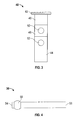
- a snap ball 58 is located adjacent a first end 54 of the pin 36 to prevent unintended movement of the pin 36 once inserted through the stem guide 30 and lock out mechanism 40 ( FIG. 4 ).
- the second end 56 of the pin 36 may be coupled to a retaining assembly 60 configured to limit movement of the pin 36 relative to the switch box 22.
- the illustrated retaining assembly 60 includes a ring 62 coupled to the second end 56 of the pin 36, and a washer 64 arranged about the lock out mechanism 40, such as between the upper surface 24 of the switch box 22 and the mounting nut 31 for example.
- a lanyard or cable 66 for example made of stainless steel, couples the ring 62 and the fixed washer 64. A sufficient length of cable 66 is provided such that insertion and removal of the pin 36 from the stem guide 30 and lock out mechanism 40 are not inhibited.
- the pin 36 When the lock out mechanism 40 is in the first position, as illustrated in FIG. 1 , the pin 36 extends through the hole 34 of the stem guide 30 as well as the aligned first through hole 50 of the shaft 44 of the lock out mechanism 40. In this first position, only the first portion 46 of the shaft 44 having a first color is visible outside the electrical switch 20. In one embodiment, when in the first position, the lock out mechanism 40 indicates that the electrical switch is operating normally and that power from the power feed line is actively flowing through the electrical switch 20 to at least one downstream component.
- the pin 36 In the second position, as illustrated in FIG. 2 , the pin 36 is arranged within the aligned through hole 34 of the stem guide 30 and the second through hole (not shown) of the shaft 44 of the lock out mechanism 40. In the second position, both the first portion 46 and the second portion 48, and therefore the first color and second color of the shaft 44 are visible outside the electrical switch 20.
- the lock out mechanism 40 when in the second position, indicates that the electrical switch 20 is in a safety mode and that the power feed line has been broken so that no power is being supplied through the electrical switch to downstream components.
- a mechanic removes the pin 36 from the stem guide 30 and shaft 44 of the lock out mechanism 40 and then applies a force to the lock out mechanism 40. Once reaching the new position, the pin 36 is positively reinserted through the stem guide 30 and the lock out mechanism 40.
- a mechanic pulls the lock out mechanism 40 to move the lock out mechanism 40 from the first position to the second position, and pushes the lock out mechanism 40 to move the lock out mechanism 40 from the second position to the first position.
- the electrical switch 20 includes an electrical lock out mechanism 40 for use in an electrically actuated system of an aircraft.
- the color coding of the lock out mechanism 40 will easily indicate to a mechanic if the switch 20 is either in normal mode operation or safety mode operation.
- the pin 36 positively retains the lock out mechanism 40 in a position.
- the positive locking pin provides a visible locking feature
Landscapes
- Switch Cases, Indication, And Locking (AREA)
Applications Claiming Priority (1)
| Application Number | Priority Date | Filing Date | Title |
|---|---|---|---|
| US13/752,918 US9064646B2 (en) | 2013-01-29 | 2013-01-29 | Electrical system lock out switch |
Publications (2)
| Publication Number | Publication Date |
|---|---|
| EP2760037A1 true EP2760037A1 (fr) | 2014-07-30 |
| EP2760037B1 EP2760037B1 (fr) | 2016-05-25 |
Family
ID=50002616
Family Applications (1)
| Application Number | Title | Priority Date | Filing Date |
|---|---|---|---|
| EP14153095.6A Not-in-force EP2760037B1 (fr) | 2013-01-29 | 2014-01-29 | Commutateur de verrouillage de système électrique |
Country Status (2)
| Country | Link |
|---|---|
| US (1) | US9064646B2 (fr) |
| EP (1) | EP2760037B1 (fr) |
Families Citing this family (7)
| Publication number | Priority date | Publication date | Assignee | Title |
|---|---|---|---|---|
| USD762441S1 (en) * | 2014-06-06 | 2016-08-02 | Grouphomesafe Limited | Lock |
| USD762440S1 (en) | 2014-06-06 | 2016-08-02 | Grouphomesafe Limited | Lock |
| US9966205B1 (en) * | 2017-03-07 | 2018-05-08 | The Boeing Company | Circuit breaker lockout system with tie-receiving channels |
| WO2020204380A1 (fr) * | 2019-04-04 | 2020-10-08 | (주)코텍 | Dispositif d'actionnement |
| WO2022192698A1 (fr) | 2021-03-12 | 2022-09-15 | Essex Industries, Inc., | Commutateur à bascule |
| US11688568B2 (en) | 2021-03-15 | 2023-06-27 | Essex Industries, Inc. | Five-position switch |
| US20240271633A1 (en) * | 2023-02-13 | 2024-08-15 | The Gorman-Rupp Company | Explosion proof motor, pump system, and method |
Citations (6)
| Publication number | Priority date | Publication date | Assignee | Title |
|---|---|---|---|---|
| US3729607A (en) * | 1971-06-23 | 1973-04-24 | Ellenberger & Poensgen | Pushbutton reset circuit breaker having peripheral contact condition indicator means |
| EP1126492A2 (fr) * | 2000-02-15 | 2001-08-22 | Eaton Corporation | Disjoncteur avec déclenchement instantané fourni par le conducteur principal passant par le circuit magnétique d'un circuit électronique de déclenchement |
| US20020158724A1 (en) * | 2001-04-30 | 2002-10-31 | Wellner Edward Louis | Circuit breaker |
| US6639492B1 (en) * | 2003-01-15 | 2003-10-28 | Eaton Corporation | Indicator reset tool, and circuit breaker and method employing the same |
| US6791040B1 (en) * | 2003-09-15 | 2004-09-14 | Eaton Corporation | Locking assembly for an electrical switching apparatus |
| US20110228509A1 (en) * | 2010-03-17 | 2011-09-22 | Steele John T | Keyless solenoid release unit |
Family Cites Families (2)
| Publication number | Priority date | Publication date | Assignee | Title |
|---|---|---|---|---|
| US5459446A (en) * | 1994-10-21 | 1995-10-17 | Texas Instruments Incorporated | Fluid splash barrier apparatus for aircraft circuit breakers and the like |
| US7570146B2 (en) * | 2007-07-25 | 2009-08-04 | Eaton Corporation | Circuit breaker including ambient compensation bimetal holding and releasing arc fault indicator |
-
2013
- 2013-01-29 US US13/752,918 patent/US9064646B2/en active Active
-
2014
- 2014-01-29 EP EP14153095.6A patent/EP2760037B1/fr not_active Not-in-force
Patent Citations (6)
| Publication number | Priority date | Publication date | Assignee | Title |
|---|---|---|---|---|
| US3729607A (en) * | 1971-06-23 | 1973-04-24 | Ellenberger & Poensgen | Pushbutton reset circuit breaker having peripheral contact condition indicator means |
| EP1126492A2 (fr) * | 2000-02-15 | 2001-08-22 | Eaton Corporation | Disjoncteur avec déclenchement instantané fourni par le conducteur principal passant par le circuit magnétique d'un circuit électronique de déclenchement |
| US20020158724A1 (en) * | 2001-04-30 | 2002-10-31 | Wellner Edward Louis | Circuit breaker |
| US6639492B1 (en) * | 2003-01-15 | 2003-10-28 | Eaton Corporation | Indicator reset tool, and circuit breaker and method employing the same |
| US6791040B1 (en) * | 2003-09-15 | 2004-09-14 | Eaton Corporation | Locking assembly for an electrical switching apparatus |
| US20110228509A1 (en) * | 2010-03-17 | 2011-09-22 | Steele John T | Keyless solenoid release unit |
Also Published As
| Publication number | Publication date |
|---|---|
| US20140209438A1 (en) | 2014-07-31 |
| US9064646B2 (en) | 2015-06-23 |
| EP2760037B1 (fr) | 2016-05-25 |
Similar Documents
| Publication | Publication Date | Title |
|---|---|---|
| EP2760037B1 (fr) | Commutateur de verrouillage de système électrique | |
| US9059533B2 (en) | Lockout and tagging device and assembly for a switchable energy isolation device such as a terminal block | |
| CN103477007A (zh) | 采用机械检测关闭和开启的锁定装置 | |
| CA2863340C (fr) | Ensemble helice et ensemble de retenue de pales d'helice | |
| CN105244205A (zh) | 一种电气控制联锁装置 | |
| EP3240007B1 (fr) | Disjoncteur actionné par solénoïde avec pince de verrouillage | |
| EP2860837A1 (fr) | Disjoncteur de circuit virtuel | |
| CN104240990A (zh) | 开关设备的闭锁装置 | |
| US11676516B2 (en) | Aircraft lockout / tagout for pushbutton switch | |
| US9362063B2 (en) | Bus plug lockout devices and related apparatus and methods | |
| CN106249671B (zh) | 一种矿用巡检有线控制机构 | |
| EP3861564B1 (fr) | Collier de protection pour actionner des éléments, en particulier des commutateurs | |
| US11649657B2 (en) | Apparatus and method for electric utility lockout device | |
| CN109416986B (zh) | 用于电气装备的断路器的远程操作的补充隔离设备 | |
| US11769641B2 (en) | Energy reducing key for electronic trip units | |
| DE102016119496A1 (de) | System zur Erfassung eines Sicherungszustands | |
| CA3051907A1 (fr) | Procedes et systemes d'isolement et d'excitation a distance d'equipement mecanique | |
| KR102830525B1 (ko) | 전동기 제어반의 도어 잠금 시스템 | |
| US9966205B1 (en) | Circuit breaker lockout system with tie-receiving channels | |
| TWM645908U (zh) | 用於防爆開關裝置之固定調整機構 | |
| EP4602633A1 (fr) | Ensemble d'actionnement manuel | |
| KR20180137058A (ko) | 공작기계용 조작반 | |
| US20130041568A1 (en) | Fuel off warning | |
| KR20160119297A (ko) | 차단기 인입출용 핸들 | |
| Hance | D0 Silicon Upgrade: Toroid Energization-Operating Procedures |
Legal Events
| Date | Code | Title | Description |
|---|---|---|---|
| PUAI | Public reference made under article 153(3) epc to a published international application that has entered the european phase |
Free format text: ORIGINAL CODE: 0009012 |
|
| 17P | Request for examination filed |
Effective date: 20140129 |
|
| AK | Designated contracting states |
Kind code of ref document: A1 Designated state(s): AL AT BE BG CH CY CZ DE DK EE ES FI FR GB GR HR HU IE IS IT LI LT LU LV MC MK MT NL NO PL PT RO RS SE SI SK SM TR |
|
| AX | Request for extension of the european patent |
Extension state: BA ME |
|
| R17P | Request for examination filed (corrected) |
Effective date: 20150127 |
|
| RBV | Designated contracting states (corrected) |
Designated state(s): AL AT BE BG CH CY CZ DE DK EE ES FI FR GB GR HR HU IE IS IT LI LT LU LV MC MK MT NL NO PL PT RO RS SE SI SK SM TR |
|
| GRAP | Despatch of communication of intention to grant a patent |
Free format text: ORIGINAL CODE: EPIDOSNIGR1 |
|
| RIC1 | Information provided on ipc code assigned before grant |
Ipc: H01H 13/14 20060101ALI20151117BHEP Ipc: H01H 83/20 20060101ALI20151117BHEP Ipc: H01H 9/28 20060101AFI20151117BHEP Ipc: H01H 9/16 20060101ALI20151117BHEP Ipc: H01H 71/58 20060101ALI20151117BHEP Ipc: H01H 71/06 20060101ALI20151117BHEP Ipc: H01H 73/16 20060101ALI20151117BHEP Ipc: H01H 71/04 20060101ALI20151117BHEP |
|
| INTG | Intention to grant announced |
Effective date: 20151208 |
|
| GRAS | Grant fee paid |
Free format text: ORIGINAL CODE: EPIDOSNIGR3 |
|
| GRAA | (expected) grant |
Free format text: ORIGINAL CODE: 0009210 |
|
| AK | Designated contracting states |
Kind code of ref document: B1 Designated state(s): AL AT BE BG CH CY CZ DE DK EE ES FI FR GB GR HR HU IE IS IT LI LT LU LV MC MK MT NL NO PL PT RO RS SE SI SK SM TR |
|
| REG | Reference to a national code |
Ref country code: GB Ref legal event code: FG4D |
|
| REG | Reference to a national code |
Ref country code: CH Ref legal event code: EP |
|
| REG | Reference to a national code |
Ref country code: IE Ref legal event code: FG4D Ref country code: AT Ref legal event code: REF Ref document number: 802925 Country of ref document: AT Kind code of ref document: T Effective date: 20160615 |
|
| REG | Reference to a national code |
Ref country code: DE Ref legal event code: R096 Ref document number: 602014002010 Country of ref document: DE |
|
| REG | Reference to a national code |
Ref country code: LT Ref legal event code: MG4D |
|
| REG | Reference to a national code |
Ref country code: NL Ref legal event code: MP Effective date: 20160525 |
|
| PG25 | Lapsed in a contracting state [announced via postgrant information from national office to epo] |
Ref country code: FI Free format text: LAPSE BECAUSE OF FAILURE TO SUBMIT A TRANSLATION OF THE DESCRIPTION OR TO PAY THE FEE WITHIN THE PRESCRIBED TIME-LIMIT Effective date: 20160525 Ref country code: NO Free format text: LAPSE BECAUSE OF FAILURE TO SUBMIT A TRANSLATION OF THE DESCRIPTION OR TO PAY THE FEE WITHIN THE PRESCRIBED TIME-LIMIT Effective date: 20160825 Ref country code: LT Free format text: LAPSE BECAUSE OF FAILURE TO SUBMIT A TRANSLATION OF THE DESCRIPTION OR TO PAY THE FEE WITHIN THE PRESCRIBED TIME-LIMIT Effective date: 20160525 Ref country code: NL Free format text: LAPSE BECAUSE OF FAILURE TO SUBMIT A TRANSLATION OF THE DESCRIPTION OR TO PAY THE FEE WITHIN THE PRESCRIBED TIME-LIMIT Effective date: 20160525 |
|
| REG | Reference to a national code |
Ref country code: AT Ref legal event code: MK05 Ref document number: 802925 Country of ref document: AT Kind code of ref document: T Effective date: 20160525 |
|
| PG25 | Lapsed in a contracting state [announced via postgrant information from national office to epo] |
Ref country code: SE Free format text: LAPSE BECAUSE OF FAILURE TO SUBMIT A TRANSLATION OF THE DESCRIPTION OR TO PAY THE FEE WITHIN THE PRESCRIBED TIME-LIMIT Effective date: 20160525 Ref country code: ES Free format text: LAPSE BECAUSE OF FAILURE TO SUBMIT A TRANSLATION OF THE DESCRIPTION OR TO PAY THE FEE WITHIN THE PRESCRIBED TIME-LIMIT Effective date: 20160525 Ref country code: LV Free format text: LAPSE BECAUSE OF FAILURE TO SUBMIT A TRANSLATION OF THE DESCRIPTION OR TO PAY THE FEE WITHIN THE PRESCRIBED TIME-LIMIT Effective date: 20160525 Ref country code: RS Free format text: LAPSE BECAUSE OF FAILURE TO SUBMIT A TRANSLATION OF THE DESCRIPTION OR TO PAY THE FEE WITHIN THE PRESCRIBED TIME-LIMIT Effective date: 20160525 Ref country code: GR Free format text: LAPSE BECAUSE OF FAILURE TO SUBMIT A TRANSLATION OF THE DESCRIPTION OR TO PAY THE FEE WITHIN THE PRESCRIBED TIME-LIMIT Effective date: 20160826 Ref country code: PT Free format text: LAPSE BECAUSE OF FAILURE TO SUBMIT A TRANSLATION OF THE DESCRIPTION OR TO PAY THE FEE WITHIN THE PRESCRIBED TIME-LIMIT Effective date: 20160926 |
|
| REG | Reference to a national code |
Ref country code: FR Ref legal event code: PLFP Year of fee payment: 4 |
|
| PG25 | Lapsed in a contracting state [announced via postgrant information from national office to epo] |
Ref country code: IT Free format text: LAPSE BECAUSE OF FAILURE TO SUBMIT A TRANSLATION OF THE DESCRIPTION OR TO PAY THE FEE WITHIN THE PRESCRIBED TIME-LIMIT Effective date: 20160525 |
|
| PG25 | Lapsed in a contracting state [announced via postgrant information from national office to epo] |
Ref country code: CZ Free format text: LAPSE BECAUSE OF FAILURE TO SUBMIT A TRANSLATION OF THE DESCRIPTION OR TO PAY THE FEE WITHIN THE PRESCRIBED TIME-LIMIT Effective date: 20160525 Ref country code: RO Free format text: LAPSE BECAUSE OF FAILURE TO SUBMIT A TRANSLATION OF THE DESCRIPTION OR TO PAY THE FEE WITHIN THE PRESCRIBED TIME-LIMIT Effective date: 20160525 Ref country code: DK Free format text: LAPSE BECAUSE OF FAILURE TO SUBMIT A TRANSLATION OF THE DESCRIPTION OR TO PAY THE FEE WITHIN THE PRESCRIBED TIME-LIMIT Effective date: 20160525 Ref country code: SK Free format text: LAPSE BECAUSE OF FAILURE TO SUBMIT A TRANSLATION OF THE DESCRIPTION OR TO PAY THE FEE WITHIN THE PRESCRIBED TIME-LIMIT Effective date: 20160525 Ref country code: EE Free format text: LAPSE BECAUSE OF FAILURE TO SUBMIT A TRANSLATION OF THE DESCRIPTION OR TO PAY THE FEE WITHIN THE PRESCRIBED TIME-LIMIT Effective date: 20160525 |
|
| PG25 | Lapsed in a contracting state [announced via postgrant information from national office to epo] |
Ref country code: BE Free format text: LAPSE BECAUSE OF FAILURE TO SUBMIT A TRANSLATION OF THE DESCRIPTION OR TO PAY THE FEE WITHIN THE PRESCRIBED TIME-LIMIT Effective date: 20160525 Ref country code: PL Free format text: LAPSE BECAUSE OF FAILURE TO SUBMIT A TRANSLATION OF THE DESCRIPTION OR TO PAY THE FEE WITHIN THE PRESCRIBED TIME-LIMIT Effective date: 20160525 Ref country code: AT Free format text: LAPSE BECAUSE OF FAILURE TO SUBMIT A TRANSLATION OF THE DESCRIPTION OR TO PAY THE FEE WITHIN THE PRESCRIBED TIME-LIMIT Effective date: 20160525 Ref country code: SM Free format text: LAPSE BECAUSE OF FAILURE TO SUBMIT A TRANSLATION OF THE DESCRIPTION OR TO PAY THE FEE WITHIN THE PRESCRIBED TIME-LIMIT Effective date: 20160525 |
|
| REG | Reference to a national code |
Ref country code: DE Ref legal event code: R097 Ref document number: 602014002010 Country of ref document: DE |
|
| PLBE | No opposition filed within time limit |
Free format text: ORIGINAL CODE: 0009261 |
|
| STAA | Information on the status of an ep patent application or granted ep patent |
Free format text: STATUS: NO OPPOSITION FILED WITHIN TIME LIMIT |
|
| 26N | No opposition filed |
Effective date: 20170228 |
|
| PG25 | Lapsed in a contracting state [announced via postgrant information from national office to epo] |
Ref country code: SI Free format text: LAPSE BECAUSE OF FAILURE TO SUBMIT A TRANSLATION OF THE DESCRIPTION OR TO PAY THE FEE WITHIN THE PRESCRIBED TIME-LIMIT Effective date: 20160525 |
|
| REG | Reference to a national code |
Ref country code: DE Ref legal event code: R119 Ref document number: 602014002010 Country of ref document: DE |
|
| REG | Reference to a national code |
Ref country code: CH Ref legal event code: PL |
|
| PG25 | Lapsed in a contracting state [announced via postgrant information from national office to epo] |
Ref country code: MC Free format text: LAPSE BECAUSE OF FAILURE TO SUBMIT A TRANSLATION OF THE DESCRIPTION OR TO PAY THE FEE WITHIN THE PRESCRIBED TIME-LIMIT Effective date: 20160525 |
|
| PG25 | Lapsed in a contracting state [announced via postgrant information from national office to epo] |
Ref country code: CH Free format text: LAPSE BECAUSE OF NON-PAYMENT OF DUE FEES Effective date: 20170131 Ref country code: LI Free format text: LAPSE BECAUSE OF NON-PAYMENT OF DUE FEES Effective date: 20170131 |
|
| REG | Reference to a national code |
Ref country code: IE Ref legal event code: MM4A |
|
| PG25 | Lapsed in a contracting state [announced via postgrant information from national office to epo] |
Ref country code: DE Free format text: LAPSE BECAUSE OF NON-PAYMENT OF DUE FEES Effective date: 20170801 Ref country code: LU Free format text: LAPSE BECAUSE OF NON-PAYMENT OF DUE FEES Effective date: 20170129 |
|
| REG | Reference to a national code |
Ref country code: FR Ref legal event code: PLFP Year of fee payment: 5 |
|
| PG25 | Lapsed in a contracting state [announced via postgrant information from national office to epo] |
Ref country code: IE Free format text: LAPSE BECAUSE OF NON-PAYMENT OF DUE FEES Effective date: 20170129 |
|
| PG25 | Lapsed in a contracting state [announced via postgrant information from national office to epo] |
Ref country code: MT Free format text: LAPSE BECAUSE OF NON-PAYMENT OF DUE FEES Effective date: 20170129 |
|
| PG25 | Lapsed in a contracting state [announced via postgrant information from national office to epo] |
Ref country code: AL Free format text: LAPSE BECAUSE OF FAILURE TO SUBMIT A TRANSLATION OF THE DESCRIPTION OR TO PAY THE FEE WITHIN THE PRESCRIBED TIME-LIMIT Effective date: 20160525 |
|
| PG25 | Lapsed in a contracting state [announced via postgrant information from national office to epo] |
Ref country code: HU Free format text: LAPSE BECAUSE OF FAILURE TO SUBMIT A TRANSLATION OF THE DESCRIPTION OR TO PAY THE FEE WITHIN THE PRESCRIBED TIME-LIMIT; INVALID AB INITIO Effective date: 20140129 |
|
| PG25 | Lapsed in a contracting state [announced via postgrant information from national office to epo] |
Ref country code: BG Free format text: LAPSE BECAUSE OF FAILURE TO SUBMIT A TRANSLATION OF THE DESCRIPTION OR TO PAY THE FEE WITHIN THE PRESCRIBED TIME-LIMIT Effective date: 20160525 |
|
| PG25 | Lapsed in a contracting state [announced via postgrant information from national office to epo] |
Ref country code: CY Free format text: LAPSE BECAUSE OF NON-PAYMENT OF DUE FEES Effective date: 20160525 |
|
| PG25 | Lapsed in a contracting state [announced via postgrant information from national office to epo] |
Ref country code: MK Free format text: LAPSE BECAUSE OF FAILURE TO SUBMIT A TRANSLATION OF THE DESCRIPTION OR TO PAY THE FEE WITHIN THE PRESCRIBED TIME-LIMIT Effective date: 20160525 |
|
| PG25 | Lapsed in a contracting state [announced via postgrant information from national office to epo] |
Ref country code: TR Free format text: LAPSE BECAUSE OF FAILURE TO SUBMIT A TRANSLATION OF THE DESCRIPTION OR TO PAY THE FEE WITHIN THE PRESCRIBED TIME-LIMIT Effective date: 20160525 |
|
| PG25 | Lapsed in a contracting state [announced via postgrant information from national office to epo] |
Ref country code: HR Free format text: LAPSE BECAUSE OF FAILURE TO SUBMIT A TRANSLATION OF THE DESCRIPTION OR TO PAY THE FEE WITHIN THE PRESCRIBED TIME-LIMIT Effective date: 20160525 |
|
| PG25 | Lapsed in a contracting state [announced via postgrant information from national office to epo] |
Ref country code: IS Free format text: LAPSE BECAUSE OF FAILURE TO SUBMIT A TRANSLATION OF THE DESCRIPTION OR TO PAY THE FEE WITHIN THE PRESCRIBED TIME-LIMIT Effective date: 20160925 |
|
| PGFP | Annual fee paid to national office [announced via postgrant information from national office to epo] |
Ref country code: GB Payment date: 20221221 Year of fee payment: 10 Ref country code: FR Payment date: 20221220 Year of fee payment: 10 |
|
| P01 | Opt-out of the competence of the unified patent court (upc) registered |
Effective date: 20230522 |
|
| GBPC | Gb: european patent ceased through non-payment of renewal fee |
Effective date: 20240129 |
|
| PG25 | Lapsed in a contracting state [announced via postgrant information from national office to epo] |
Ref country code: GB Free format text: LAPSE BECAUSE OF NON-PAYMENT OF DUE FEES Effective date: 20240129 |
|
| PG25 | Lapsed in a contracting state [announced via postgrant information from national office to epo] |
Ref country code: FR Free format text: LAPSE BECAUSE OF NON-PAYMENT OF DUE FEES Effective date: 20240131 |
|
| PG25 | Lapsed in a contracting state [announced via postgrant information from national office to epo] |
Ref country code: GB Free format text: LAPSE BECAUSE OF NON-PAYMENT OF DUE FEES Effective date: 20240129 Ref country code: FR Free format text: LAPSE BECAUSE OF NON-PAYMENT OF DUE FEES Effective date: 20240131 |