EP2760126A2 - Commande de moteur sans capteur - Google Patents
Commande de moteur sans capteur Download PDFInfo
- Publication number
- EP2760126A2 EP2760126A2 EP13190607.5A EP13190607A EP2760126A2 EP 2760126 A2 EP2760126 A2 EP 2760126A2 EP 13190607 A EP13190607 A EP 13190607A EP 2760126 A2 EP2760126 A2 EP 2760126A2
- Authority
- EP
- European Patent Office
- Prior art keywords
- motor
- speed
- current
- voltage
- control system
- Prior art date
- Legal status (The legal status is an assumption and is not a legal conclusion. Google has not performed a legal analysis and makes no representation as to the accuracy of the status listed.)
- Withdrawn
Links
- 230000004907 flux Effects 0.000 claims description 11
- 230000003313 weakening effect Effects 0.000 claims description 11
- 238000000034 method Methods 0.000 claims description 10
- 230000001172 regenerating effect Effects 0.000 claims description 7
- 230000007246 mechanism Effects 0.000 description 18
- 238000006243 chemical reaction Methods 0.000 description 8
- 230000007423 decrease Effects 0.000 description 8
- 230000001965 increasing effect Effects 0.000 description 8
- 230000006698 induction Effects 0.000 description 6
- 239000003990 capacitor Substances 0.000 description 5
- 230000001276 controlling effect Effects 0.000 description 5
- 238000004590 computer program Methods 0.000 description 4
- 238000004804 winding Methods 0.000 description 4
- 238000004364 calculation method Methods 0.000 description 3
- 230000006870 function Effects 0.000 description 3
- 230000001360 synchronised effect Effects 0.000 description 3
- 238000013459 approach Methods 0.000 description 2
- 230000003190 augmentative effect Effects 0.000 description 2
- 230000008859 change Effects 0.000 description 2
- 238000010586 diagram Methods 0.000 description 2
- 238000005516 engineering process Methods 0.000 description 2
- 230000003044 adaptive effect Effects 0.000 description 1
- 239000004020 conductor Substances 0.000 description 1
- 230000003247 decreasing effect Effects 0.000 description 1
- 230000003467 diminishing effect Effects 0.000 description 1
- 230000005674 electromagnetic induction Effects 0.000 description 1
- 230000001939 inductive effect Effects 0.000 description 1
- 230000010354 integration Effects 0.000 description 1
- 230000003287 optical effect Effects 0.000 description 1
- 230000010355 oscillation Effects 0.000 description 1
- 230000008569 process Effects 0.000 description 1
- 230000001105 regulatory effect Effects 0.000 description 1
- 239000004065 semiconductor Substances 0.000 description 1
- 238000006467 substitution reaction Methods 0.000 description 1
- 238000005406 washing Methods 0.000 description 1
Images

Classifications
-
- H—ELECTRICITY
- H02—GENERATION; CONVERSION OR DISTRIBUTION OF ELECTRIC POWER
- H02P—CONTROL OR REGULATION OF ELECTRIC MOTORS, ELECTRIC GENERATORS OR DYNAMO-ELECTRIC CONVERTERS; CONTROLLING TRANSFORMERS, REACTORS OR CHOKE COILS
- H02P21/00—Arrangements or methods for the control of electric machines by vector control, e.g. by control of field orientation
- H02P21/14—Estimation or adaptation of machine parameters, e.g. flux, current or voltage
- H02P21/18—Estimation of position or speed
-
- H—ELECTRICITY
- H02—GENERATION; CONVERSION OR DISTRIBUTION OF ELECTRIC POWER
- H02P—CONTROL OR REGULATION OF ELECTRIC MOTORS, ELECTRIC GENERATORS OR DYNAMO-ELECTRIC CONVERTERS; CONTROLLING TRANSFORMERS, REACTORS OR CHOKE COILS
- H02P6/00—Arrangements for controlling synchronous motors or other dynamo-electric motors using electronic commutation dependent on the rotor position; Electronic commutators therefor
- H02P6/14—Electronic commutators
- H02P6/16—Circuit arrangements for detecting position
- H02P6/18—Circuit arrangements for detecting position without separate position detecting elements
- H02P6/181—Circuit arrangements for detecting position without separate position detecting elements using different methods depending on the speed
-
- H—ELECTRICITY
- H02—GENERATION; CONVERSION OR DISTRIBUTION OF ELECTRIC POWER
- H02P—CONTROL OR REGULATION OF ELECTRIC MOTORS, ELECTRIC GENERATORS OR DYNAMO-ELECTRIC CONVERTERS; CONTROLLING TRANSFORMERS, REACTORS OR CHOKE COILS
- H02P21/00—Arrangements or methods for the control of electric machines by vector control, e.g. by control of field orientation
- H02P21/0003—Control strategies in general, e.g. linear type, e.g. P, PI, PID, using robust control
- H02P21/0021—Control strategies in general, e.g. linear type, e.g. P, PI, PID, using robust control using different modes of control depending on a parameter, e.g. the speed
-
- H—ELECTRICITY
- H02—GENERATION; CONVERSION OR DISTRIBUTION OF ELECTRIC POWER
- H02P—CONTROL OR REGULATION OF ELECTRIC MOTORS, ELECTRIC GENERATORS OR DYNAMO-ELECTRIC CONVERTERS; CONTROLLING TRANSFORMERS, REACTORS OR CHOKE COILS
- H02P21/00—Arrangements or methods for the control of electric machines by vector control, e.g. by control of field orientation
- H02P21/0085—Arrangements or methods for the control of electric machines by vector control, e.g. by control of field orientation specially adapted for high speeds, e.g. above nominal speed
- H02P21/0089—Arrangements or methods for the control of electric machines by vector control, e.g. by control of field orientation specially adapted for high speeds, e.g. above nominal speed using field weakening
-
- H—ELECTRICITY
- H02—GENERATION; CONVERSION OR DISTRIBUTION OF ELECTRIC POWER
- H02P—CONTROL OR REGULATION OF ELECTRIC MOTORS, ELECTRIC GENERATORS OR DYNAMO-ELECTRIC CONVERTERS; CONTROLLING TRANSFORMERS, REACTORS OR CHOKE COILS
- H02P21/00—Arrangements or methods for the control of electric machines by vector control, e.g. by control of field orientation
- H02P21/24—Vector control not involving the use of rotor position or rotor speed sensors
- H02P21/26—Rotor flux based control
-
- H—ELECTRICITY
- H02—GENERATION; CONVERSION OR DISTRIBUTION OF ELECTRIC POWER
- H02P—CONTROL OR REGULATION OF ELECTRIC MOTORS, ELECTRIC GENERATORS OR DYNAMO-ELECTRIC CONVERTERS; CONTROLLING TRANSFORMERS, REACTORS OR CHOKE COILS
- H02P2205/00—Indexing scheme relating to controlling arrangements characterised by the control loops
- H02P2205/07—Speed loop, i.e. comparison of the motor speed with a speed reference
Definitions
- Embodiments of the present invention relate to systems and methods for controlling electric motors.
- Electric motors commonly include a stationary component called a stator and a rotating component called a rotor.
- the rotor rotates within (or around) the stator when the motor is energized with a driving waveform.
- Induction motors sometimes referred to as asynchronous motors, are a type of electric motor wherein power is supplied to the rotor by means of electromagnetic induction rather than by means of direct electrical connections to the rotor.
- the driving waveform supplied to an induction motor's stator creates a magnetic field that rotates in time with the AC oscillations of the driving waveform.
- the induction motor's rotor rotates at a slower speed than the stator field.
- This difference in rotational speed also referred to as "slip,” “slip frequency,” or “slip speed” results in a changing magnetic flux in the rotor windings that induces currents in the rotor windings.
- the induced current in turn generates magnetic fields in the rotor windings that oppose the rotating magnetic field created by the stator, thereby inducing rotational movement in the rotor.
- the rotor accelerates until the magnitude of induced rotor current and rotor torque balances the applied load. Since rotation at synchronous speed would result in no induced rotor current, an induction motor always operates at less than synchronous speed during normal forward operation.
- the rotating magnetic field created by the stator induces rotational pressure on the rotor that opposes the rotor's movement and reduces motor speed.
- the inertia of the rotor and applied load induces voltage in the stator that may energize external motor components, such as a DC bus supplying power to the motor.
- a known method of controlling electric motors is field oriented control or "FOC.”
- Field oriented control involves controlling a motor using three motor input variables including voltage magnitude, voltage angle and frequency. Because stator current is closely related to output torque and other operating characteristics of the motor, it is desirable to use field oriented control methods to operate the motor according to a target stator current. At high motor speeds, however, manipulating the stator current using field oriented control becomes less effective because the motor operates at or near a maximum voltage level, eliminating or reducing one of the input variables (voltage magnitude).
- Embodiments of the present invention solve the above described problems by providing improved systems for controlling electric motors that are capable of operating in different operating modes according to the operating speed of the motor.
- a motor control system constructed in accordance with an embodiment of the present invention comprises a power inverter, control circuitry configured to control the power inverter either according to a target voltage in a voltage-based control mode or according to a target current in a current-based control mode, and a controller for switching operation of the control circuitry between the voltage-based control mode and the current-based control mode.
- the control circuitry includes a plurality of regulators for generating and/or adjusting motor control signals.
- a first regulator receives a differential speed signal and generates a torque producing component i qref of a reference current signal based on the differential speed signal, the differential speed signal representing a difference between a reference motor speed and an estimated motor speed.
- a second regulator receives a reference speed signal and generates a flux producing component i dref of the reference current signal.
- a third regulator receives a differential i q signal and generates a torque producing component V q of a reference voltage signal, the differential i q signal representing a difference between i qref and an estimated actual torque producing component i q of a motor driving waveform.
- a fourth regulator receives a differential i d signal and generates a flux producing component V d of the reference voltage signal based on the differential i d signal, the differential i d signal representing a difference between i dref and an estimated actual flux producing component i d of the motor driving waveform.
- a method of operating a motor control system comprises generating a first motor drive signal according to a target current if a reference motor speed is within a first speed range and generating a second motor drive signal according to a target voltage if the reference motor speed is within a second speed range.
- the method further comprises automatically switching operation of the motor control system between generating the first motor drive signal and generating the second motor drive signal as the target speed changes between the first speed range and the second speed range.
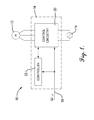
- Fig. 1 is a block diagram of a motor system constructed in accordance with embodiments of the invention.
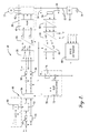
- Fig. 2 is a schematic representation of control circuitry for use with the motor system of Fig. 1 .
- Fig. 3 is a schematic representation of an alternative embodiment of the control circuitry of Fig. 2 .
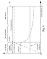
- Fig. 4 is a graphical representation of certain operating and performance characteristics of the motor of Fig. 1 .
- references to “one embodiment”, “an embodiment”, or “embodiments” mean that the feature or features being referred to are included in at least one embodiment of the technology.
- references to “one embodiment”, “an embodiment”, or “embodiments” in this description do not necessarily refer to the same embodiment and are also not mutually exclusive unless so stated and/or except as will be readily apparent to those skilled in the art from the description.
- a feature, structure, act, etcetera described in one embodiment may also be included in other embodiments, but is not necessarily included.
- the present technology can include a variety of combinations and/or integrations of the embodiments described herein.
- the motor system 10 broadly includes an electric motor 12, a power source 14, and a motor control system 16 for receiving power from the power source 14 and generating a driving waveform to power the motor 12 according to a reference motor speed ( ⁇ ref ) communicated to the control system via a reference speed input 18.
- the reference motor speed corresponds to a desired or target operating motor output speed and may be generated by an external motor control mechanism (not illustrated) configured to operate the motor 12 according to a particular implementation of the invention.
- the motor control system 16 includes control circuitry 20 configured to receive input power from the power source 14, receive a reference motor speed signal from the reference speed input 18, create the driving waveform, and communicate the driving waveform to the motor 12.
- a controller 22 manages certain aspects of the operation of the control circuitry 20, including switching between a voltage-based control mode and a current-based control mode, as explained below.
- the power source 14 may be a conventional alternating-current power source, such as a standard 115V or 230V source available in residential and commercial buildings via standard electrical outlets.
- the motor system 10 may be part of an appliance drive system, such as a washing machine or a clothes dryer, that includes additional electrical and mechanical components not illustrated or described herein.
- the motor 12 may be an electric induction motor and, in one exemplary embodiment, is a three-phase, four-pole AC induction motor rated to operate at a maximum voltage of between 190 and 200 volts and a maximum current of between 4 and 6 amps.
- the motor 12 may be configured to operate within a normal operating range of, for example, between 0 and 3,000 rpm, and may be capable of operating at speeds well beyond the normal operation range, such as up to 17,000 or 18,000 rpm. Motor operation beyond the normal operating range may be characterized by progressively diminishing performance characteristics, such as decreased torque, as explained below.
- FIG. 4 Various operating and performance characteristics of the motor 12, including stator voltage (V s ), maximum operating current and output torque, are illustrated in the graph of Fig. 4 across the operating speed range of the motor 12.
- V s stator voltage
- Fig. 4 motor performance characteristics differ according to whether the motor is operating in a normal operating region or a field weakening region.
- the normal operating region corresponds to a motor output speed of zero up to a nominal operating speed 24, which may be, for example, 3,000 or 4,000 rpm.
- the field weakening operating region corresponds to the nominal speed 24 up to a maximum motor speed 26, which may be, for example, about 17,000 or 18,000 rpm.
- the speed of the motor 12 When operating in the normal operating region, the speed of the motor 12 generally follows a linear pattern and is proportional to the stator voltage (V s ), while torque is generally constant. In the field weakening region, the stator voltage remains at or near a maximum operating voltage and the torque diminishes as the motor output speed increases.
- the maximum operating current is defined by limitations of the motor 12, the control circuitry 20, or both. While the maximum operating current generally remains constant across all motor operating speeds, the motor stator current (is) will typically fluctuate with changing operational parameters, such as changes in motor speed and load torque.
- the motor 12 generally operates in three different output speed ranges including low speed, medium speed and high speed.
- the low speed range generally corresponds to the normal operating region
- the medium speed range generally corresponds to a lower portion of the field weakening region
- the high speed range general corresponds to an upper portion of the field weakening region, as indicated in the graph of Fig. 4 .
- the motor speed corresponding to the boundary between the medium and high speed ranges may be defined as a particular motor speed, such as 8,000 rpm or 10,000 rpm, or as a percentage of a maximum motor speed, such as 50%, 60% or 70% of the maximum speed 26.
- the boundary may be defined in terms of the stator current, such as a particular value of i sd or i sq or a difference between i sd and i sq .
- the boundary between the medium and high speed ranges may be defined in terms of the torque, such as a particular torque value or percentage of maximum torque.
- the boundary between the medium and high speed ranges is relevant in that may be used by the controller as a threshold speed for switching between the voltage-based control mode and the current-based control mode, as explained below.
- the boundary between the medium and high speed ranges is defined as a rotor speed at which the stator voltage amplitude is at or near the inverter voltage margin. When the motor is operating at or near the inverter voltage margin, fluctuations in the inverter voltage margin due to, for example, variations in the DC bus voltage make current-based motor control impractical.
- the controller 22 includes digital logic configured to interact with and control certain components of the control circuitry 20.
- the digital logic may include discrete logic components, programmable logic devices and/or general purpose computer processors such as microcontrollers or microprocessors.
- the controller 22 is or includes a computer processor configured to execute a computer program for directing the control circuitry 20 to operate in either the current-based control mode in the low and medium speed ranges or in the voltage-based control mode in the high speed range.
- aspects of the invention may be implemented with one or more computer programs stored in or on computer-readable media residing in or accessible by the controller 22.
- the computer program comprises a series of executable instructions for implementing logical functions in the controller 22.
- the computer program can be embodied in any non-transitory computer-readable medium for use by or in connection with the controller 22 wherein the controller fetches instructions from the computer-readable medium and executes the instructions.
- a "computer-readable medium” can be any non-transitory means that can store the program for use by or in connection with the controller.
- the computer-readable medium can be, for example, but is not limited to, an electronic, magnetic, optical, electro-magnetic, infrared, or semiconductor system, apparatus, or device.
- examples of the computer-readable medium would include the following: an electrical connection having one or more wires, a random access memory (RAM), a read-only memory (ROM), and an erasable, programmable, read-only memory (EPROM or Flash memory).
- RAM random access memory
- ROM read-only memory
- EPROM erasable, programmable, read-only memory
- a rectifier 30 converts AC power received from the power source 14 to DC power that energizes a DC bus 32.
- the rectifier 30 may include virtually any type of rectifier circuit, but in various preferred embodiments is a simple non-regenerative rectifier, such as a diode bridge rectifier.
- a signal shunt 34 and voltage sensor 35 are coupled with the DC bus 32 and used to detect voltage and/or current levels on the DC bus 32 for use in feedback loops, as explained below in greater detail.
- the signal shunt 34 may be, for example, a resister, while the voltage sensor 35 may be a voltage divider circuit.
- One or more capacitors 36 are also coupled to the DC bus 32 to minimize voltage ripple on the bus 32 and to store regenerative energy in the bus 32 during braking.
- Inverter circuitry 38 includes pulse width modulation (“PWM”) control logic 40 and a three-phase inverter 42 that converts DC power from the DC bus 32 to driving waveforms that are communicated to the motor 12.
- PWM control logic 40 receives two input signals (V ⁇ ref and V ⁇ ref ) representing two-phase stationary reference frame voltage values V ⁇ and V ⁇ , and converts the input signals to inverter control signals that drive the inverter to convert power from the DC bus 32 to the driving waveforms applied to the motor stator windings.
- the voltage magnitude, voltage angle and frequency of the driving electric waveforms are manipulated according to the reference motor speed ⁇ ref to control operation of the motor 12.
- the motor 12 When the motor 12 is operating at a constant speed or accelerating, it has a positive slip frequency and generally consumes energy. When the motor 12 is decelerating (braking), it has a negative slip frequency and generates energy that is dissipated in the motor 12 (as rotor and stator losses) and that energizes the inverter 42 and the DC bus 32, thereby increasing the voltage in those components beyond the voltage supplied by the rectifier 30. The increased voltage on the DC bus 32 may contribute to braking by further increasing stator voltages and losses in the motor 12, as explained below in greater detail.
- the control circuitry 20 When the switch 28 is in a first position (represented by the broken lines in Fig. 2 ), the control circuitry 20 operates in the current-based control mode according to principles of indirect field oriented control (IFOC). In the current-based control mode, the control circuitry 20 drives operation of the power inverter 42 according to a target stator current.
- IFOC motor control method involves controlling AC motor operation by means of three motor input variables: voltage magnitude, voltage angle and signal frequency. These variables are manipulated according to the reference speed ⁇ ref via two control/feedback loops that independently control the speed (frequency) and strength of the rotating magnetic field induced in the motor's stator.
- the reference motor speed ( ⁇ ref ) signal is received at the left side of the circuit diagram in Fig. 1 .
- the ⁇ ref signal may be received from an external motor controller, such as an appliance motor controller configured to control the speed and operation of the motor according to operational parameters of the particular appliance.
- An estimated rotor speed, ⁇ r is subtracted from the reference speed and the difference is communicated to a first proportional-integral controller 44 configured to generate a torque-producing component i qref of a target stator current.
- the estimated motor speed ( ⁇ r ) is also communicated to a field weakening controller 46 configured to generate a flux-producing component i dref of the stator current.
- the field weakening controller 46 decreases the value of i dref when the reference motor speed is in the field weakening region of motor operation.
- the i qref signal is communicated from the first proportional-integral controller 44 to a DC voltage limiter circuit 48 that is configured to limit the maximum negative value of i qref based on the voltage limitations of the motor 12, inverter 42 and/or capacitor 36.
- the value of i qref is negative during motor braking when the reference motor speed is less than the actual rotor speed.
- the voltage limiter circuit 48 prevents the negative value of i qref from exceeding a level corresponding to the maximum voltage of the motor, inverter and/or capacitor.
- the voltage limiter circuit 48 receives a first signal V dcmax representing a maximum voltage level, a second signal V dc representing an estimated or measured voltage on the DC bus 32, and subtracts the value of V dc from V dcmax .
- An integrator controller 50 integrates the difference and communicates the result, -i qrefmax , to a first current limiter component 52 that limits i qref to the value of -i qrefmax .
- a current limiter component 54 receives both i qref and i dref signals and imposes a limit on the signals corresponding to a maximum stator current as defined by a maximum rating of the motor 12 and/or the inverter 42. Thus, while the voltage limiter circuit 48 imposes a maximum negative value of i qref during braking to regulate regenerative voltage, the current limiter component 54 imposes a maximum positive value of i qref and i dref during normal operation.
- Measured values of the torque-producing component i q and the flux-producing component i d of the actual stator current are subtracted from i qref and i dref , and the resulting difference is communicated to second 56 and third 58 proportional-integral controllers which calculate rotating two-phase voltage signals V qref and V dref .
- An inverse Park conversion circuit 60 converts the V qref and V dref signals to stationary two-phase signals V ⁇ ref and V ⁇ ref which are received by the PWM control logic 40 of the inverter circuitry 38.
- the PWM control logic 40 generates a plurality of inverter control signals based on the stationary two-phase signals V ⁇ ref and V ⁇ ref , as explained above, and communicates the control signals to the inverter 42.
- the control circuitry 20 uses feedback loops to generate the motor control signals.
- the shunt 34 and sensor 35 detect current and/or voltage on the DC bus 32 and communicate the information to a converter component 62 that generates a plurality of signals representing measured values of the instantaneous stator current and/or voltage.
- a Clarke conversion circuit 64 converts the measured stator current and/or voltage values to two-phase, stationary values i ⁇ and i ⁇ , which are then converted to two-phase rotating signals i q and i d by a Park conversion circuit 66.
- the i q and i d signals are combined with the i qref and i dref signals, as explained above.
- the Clarke conversion circuit 64 may also generate two-phase, stationary values V ⁇ and V ⁇ that are used by a speed estimator 68 to estimate the rotor speed ⁇ r .
- the speed estimator 68 calculates an estimated rotor speed, ⁇ r , based on characteristics of the power communicated to the stator, such as the estimated values i ⁇ , i ⁇ , V ⁇ and V ⁇ generated by the Clarke conversion circuit 64.
- the speed estimator 68 uses, for example, model reference adaptive system (MRAS) principles of operation.
- MRAS model reference adaptive system
- the ⁇ r signal is combined with ⁇ ref to generate i qref , as explained above.
- the ⁇ r signal is also used by an output angle calculation circuit 70 to generate an output angle signal ⁇ dq that is used by the Clarke and inverse Clarke conversion circuits to translate between the stationary and rotating domains.
- the output angle calculation circuit 70 includes a slip calculator 72 that determines slip frequency, ⁇ s , as a function of i qref and i dref .
- the slip frequency is combined with the estimated rotor frequency, ⁇ r , and that combination is integrated using an integrator 74 to generate the output angle signal ⁇ dq .
- control circuitry 20 uses two independent feedback loops to control the strength and speed of the rotating magnetic field induced in the stator.
- a first feedback loop controls the strength of the rotating magnetic field and includes the Park 66 and Clarke 64 conversion circuits and the proportional-integral controllers 56, 58.
- a second feedback loop controls the speed of the rotating magnetic field and includes the Clarke conversion circuit 64, the speed estimator 68, the first proportional-integral controller 44, the field weakening controller 46 and the output angle calculation circuit 70.
- V dref is set to zero and V qref is set to V rated , which may correspond to the maximum operating voltage.
- the maximum operating voltage will typically be the voltage available on the DC bus 32, but may also be related to the maximum voltage capacity of the inverter 42 and/or the motor 12.
- the control circuitry 20 operates the inverter 42 according to a target voltage (V rated ) rather than a target current.
- V rated a target voltage
- This mode of operation may be desirable, for example, where the motor 12 is operating at very high speeds and stator voltage is at or near the maximum voltage. In such situations, the voltage-based control mode allows greater power to be delivered to the motor 12 because the voltage margins associated the current-based control mode are eliminated.
- Control circuitry 100 constructed according to another embodiment of the invention is illustrated in Fig. 3 .
- the control circuitry 100 is identical to the control circuitry 20 illustrated in Fig. 2 and described above, except that the control circuitry 100 includes brake mechanisms for regulating the braking power of the motor 12 when the control circuitry 100 is operating in either the current-based control mode or in the voltage-based control mode. Therefore, for convenience similar components are assigned the same reference numerals and only the differences between the two embodiments will be discussed. Particularly, a current-based braking mechanism 102 is used when the circuitry 100 is operating in the current-based control mode and a voltage-based braking mechanism 104 is used when the circuitry 100 is operating in the voltage-based control mode.
- the current-based brake mechanism 102 determines a difference between a change in the reference speed ( ⁇ ref ) and a change in the estimated rotor speed ( ⁇ r ). That difference is integrated using an integrator controller 106 to generate a differential speed signal ⁇ i dref that is combined with the i dref signal when braking in the current-based control mode.
- the current-based braking mechanism 102 augments the i dref signal according to a difference between the reference motor speed ⁇ ref and the estimated rotor speed ⁇ r thereby increasing motor losses and causing the motor to slow at a quicker rate.
- the difference between the reference motor speed and the estimated motor speed increases, so does the value of ⁇ i dref and i dref .
- a first braking switch 108 is operable to selectively connect the output of the current-based braking mechanism 102 to the i dref signal combination point.
- the controller 22 may be configured to actuate the switch 108 to connect the current-based braking mechanism 102 to the i dref signal combination point when the motor is in braking mode (i.e., when ⁇ ref is less than ⁇ r ).
- the voltage-based braking mechanism 104 augments the V rated input to increase motor losses during braking when the control circuitry 20 is operating in the voltage-based control mode.
- the voltage-based braking mechanism 104 is similar in form and function to the current-based braking mechanism 102, described above, such that the braking signal increases with a difference between the reference speed and the estimated rotor speed. Augmenting the V rated input causes the voltage applied to the motor to increase as well, thus increasing motor losses during braking and causing the motor to slow at a quicker rate.
- Increasing the voltage applied to the motor also increases the level of energy generated in the inverter and on the DC bus by the motor, which in turn increases the amount of voltage available to be applied to the motor, further increasing motor losses and braking power.
- a second braking switch 110 is operable to selectively connect the output of the voltage-based braking mechanism 104 to the V rated signal combination point.
- the controller 22 may be configured to actuate the switch 110 to connect the voltage-based braking mechanism 104 to the V rated signal combination point when the motor is in braking mode (i.e., when ⁇ ref is less than ⁇ r ).
- the amount of energy generated in the inverter 42 and the DC bus 32 by the motor 12 during braking will generally be limited by the rated capacity of the motor 12, the inverter 42 and/or the capacitor 36.
- voltage generated on the DC bus 32 by the motor 12 is limited by the voltage limiting circuit 48.
- the voltage limiting circuit 48 regulates both i qref and the motor slip frequency to limit energy generation in the inverter 42 and on the DC bus 32 and thus avoid damage to those components.
- the voltage limiting circuit 48 regulates only the slip frequency.
- the braking mechanisms 102, 104 provide enhanced braking without compromising control of the braking process.
- the speed of the motor 12, for example, is tracked by the speed estimator 68 such that braking is enabled to decrease motor speed to any speed, including speeds other than zero. It may be desirable, for example, to slow the motor speed from 5,000 rpm to 3,000 rpm.
- the controller 22 actuates the circuit control switch 28 to shift operation of the control circuit between the voltage-based control mode and the current-based control mode.
- the controller 22 further actuates the first brake switch 108 and the second brake switch 110 to use the brake mechanisms 102, 104 when in braking mode.
- Operation of the motor system 10 typically begins when the actual speed of the motor is zero and some non-zero reference speed is applied to the motor control system 16.
- the controller 22 actuates the circuit control switch 28 such that the switch 28 is in the first position to place the control circuitry in the current-based control mode.
- the control circuitry 20 generates a driving waveform causing the motor speed to gradually increase toward the motor reference speed.
- the stator voltage increases linearly with the speed of the motor 12, as illustrated in Fig. 4 . If the reference motor speed ⁇ ref is in the normal operating region, the actual motor speed reaches the reference speed and stabilizes, and the control circuit 20 continues to drive the motor 12 at the reference speed in the current-based control mode.
- the control circuitry 20 causes the motor speed to increase such that the stator voltage increases to and remains near the maximum available voltage as the actual motor speed reaches the nominal operating speed threshold.
- the motor speed continues to increase in the field weakening region as the torque-producing component of the stator current increases, the flux-producing component of the stator current decreases, and the motor torque decreases.
- the actual motor speed eventually reaches the reference speed and stabilizes, and the control circuit 20 continues to drive the motor 12 at the reference speed in the current-based control mode.
- the controller 22 continues to increase the motor speed in the current-based control mode until the estimated motor speed ⁇ r reaches the high speed range, wherein the controller 22 drives the switch 28 from the first position to the second position, shifting the control circuitry 20 from the current-based control mode to the voltage-based control mode.
- the control circuitry 20 operates the motor 12 at the maximum rated voltage, as explained above. As long as the reference motor speed remains in the high speed range, the control circuitry 20 continues to operate in the voltage-based control mode.
- the control circuitry 20 adjusts i qref and i dref causing the motor to operate at a negative slip frequency until ⁇ r decreases to correspond to ⁇ ref .
- Operating at a negative slip frequency uses the driving waveform against the motor's movement and therefore acts as a brake. In this braking mode, the motor's movement generates electrical energy that may drive up the voltage in the inverter 42 and/or the DC bus 32. If the voltage in the inverter 42 and/or the DC bus 32 approaches the maximum voltage V dcmax , the voltage limiting circuit 48 responds by limiting the negative slip frequency to thereby limit the V dc value and prevent damaging overvoltage.
- control circuitry 20 includes the voltage-based braking mechanism 104, as soon as the reference motor speed decreases to a level below the estimated speed ⁇ r , the controller 22 drives the second brake switch 110 to combine the voltage value V rated with V qref and thereby increase braking power. When the actual motor speed approaches or reaches the reference motor speed, the controller 22 drives the second brake switch 110 to disengage the braking mechanism 104 from the control circuitry 20.
- the control circuitry 20 continues to operate in the voltage-based control mode. If the reference speed decreases from the high speed range to the middle or low speed range, however, the controller 22 switches operation of the control circuitry 20 from the voltage-based control mode to the current-based control mode by driving the switch 28 from the second position to the first position. If the motor system 10 brakes while in the current-based control mode, the controller 22 drives the first brake switch 108 to engage the current-based braking mechanism 102 as explained above, thereby augmenting the i dref signal and increasing braking power.
- the advantages of the present invention will be apparent to those skilled in the art.
- the design of the motor system 10 minimizes costs in that it does not require the use of a braking resistor, a regenerative front-end diode bridge, or motor shaft speed sensors.
- the system 10 operates at maximum efficiency by operating according to a target current at lower speeds where the current margin governs operation, and operating according to a target voltage at higher speeds where the voltage margin governs operation.
- the motor system 10 includes an enhanced braking system that can quickly brake the motor to any speed without losing the ability to measure the motor's speed.
- the motor control system may be powered by a direct current source, for example, rather than the alternating current source as illustrated, wherein the rectifier may be omitted.
- the stator current and voltage values used in the control loops may be derived directly from motor input conductors rather than from the DC bus.
Landscapes
- Engineering & Computer Science (AREA)
- Power Engineering (AREA)
- Control Of Ac Motors In General (AREA)
Applications Claiming Priority (1)
| Application Number | Priority Date | Filing Date | Title |
|---|---|---|---|
| US13/753,277 US9160262B2 (en) | 2013-01-29 | 2013-01-29 | Sensorless motor control |
Publications (2)
| Publication Number | Publication Date |
|---|---|
| EP2760126A2 true EP2760126A2 (fr) | 2014-07-30 |
| EP2760126A3 EP2760126A3 (fr) | 2017-12-20 |
Family
ID=49485637
Family Applications (1)
| Application Number | Title | Priority Date | Filing Date |
|---|---|---|---|
| EP13190607.5A Withdrawn EP2760126A3 (fr) | 2013-01-29 | 2013-10-29 | Commande de moteur sans capteur |
Country Status (3)
| Country | Link |
|---|---|
| US (1) | US9160262B2 (fr) |
| EP (1) | EP2760126A3 (fr) |
| CN (2) | CN103973190B (fr) |
Families Citing this family (19)
| Publication number | Priority date | Publication date | Assignee | Title |
|---|---|---|---|---|
| US9160262B2 (en) * | 2013-01-29 | 2015-10-13 | Nidec Motor Corporation | Sensorless motor control |
| US20150084576A1 (en) * | 2013-05-03 | 2015-03-26 | Texas Instruments Incorporated | Low Speed and High Speed Controller Architecture for Electric Motors |
| US9545871B2 (en) * | 2013-08-09 | 2017-01-17 | Lippert Components Manufacturing, Inc. | In-vehicle lift mechanism |
| US9887648B2 (en) * | 2013-10-31 | 2018-02-06 | Yaskawa America, Inc. | Motor speed control with speed foldback for phase imbalance protection |
| US10027261B2 (en) * | 2014-03-05 | 2018-07-17 | Nidec Servo Corporation | Motor apparatus |
| SE538656C2 (en) * | 2014-10-30 | 2016-10-11 | Scania Cv Ab | Method and system for switching from a first power supply path to a second power supply path |
| US9673743B1 (en) | 2016-09-08 | 2017-06-06 | Limiter Power Management System (PTY) LTD. | Efficient motor control |
| US11018610B2 (en) | 2017-01-27 | 2021-05-25 | Franklin Electric Co., Inc. | Motor drive system and method |
| KR101861986B1 (ko) * | 2017-02-03 | 2018-05-29 | 엘에스산전 주식회사 | 인버터 제어장치 |
| WO2019241272A1 (fr) | 2018-06-11 | 2019-12-19 | Broan-Nutone Llc | Système de ventilation à équilibrage automatique de flux dérivé d'un réseau de neurones artificiels et procédés d'utilisation |
| JP6855435B2 (ja) | 2018-12-25 | 2021-04-07 | アイシン精機株式会社 | 電動ポンプ |
| CN113710427B (zh) * | 2019-04-24 | 2024-04-26 | 松下知识产权经营株式会社 | 电动工具 |
| CN109995298B (zh) * | 2019-05-10 | 2020-11-10 | 中山大洋电机股份有限公司 | 无位置传感器矢量控制永磁同步电机平滑启动控制方法 |
| EP3817219A1 (fr) * | 2019-11-04 | 2021-05-05 | Schneider Toshiba Inverter Europe SAS | Procédé d'estimation des paramètres mécaniques d'un moteur électrique |
| US11196371B2 (en) | 2020-01-10 | 2021-12-07 | DRiV Automotive Inc. | Sensorless position detection for electric motor |
| US11609137B2 (en) | 2020-03-30 | 2023-03-21 | Rockwell Automation Technologies, Inc. | Estimating motor drive torque and velocity |
| CN112134503B (zh) * | 2020-09-22 | 2025-01-24 | 新代科技(苏州)有限公司 | 致动装置及其驱动方法 |
| US12088156B2 (en) | 2022-06-28 | 2024-09-10 | Ford Global Technologies, Llc | Rotor position-based ramp rate to reduce vehicle harshness during active discharge |
| US20250096714A1 (en) * | 2023-09-19 | 2025-03-20 | Steering Solutions Ip Holding Corporation | Feedback current control of induction machines |
Family Cites Families (13)
| Publication number | Priority date | Publication date | Assignee | Title |
|---|---|---|---|---|
| US5032771A (en) * | 1990-08-09 | 1991-07-16 | Allen-Bradley Company, Inc. | Slip control based on sensing voltage fed to an induction motor |
| US5479081A (en) * | 1993-12-23 | 1995-12-26 | Allen-Bradley Company, Inc. | AC motor controller with voltage margin adjustment |
| US5739664A (en) * | 1996-02-05 | 1998-04-14 | Ford Global Technologies, Inc. | Induction motor drive controller |
| US5717305A (en) * | 1996-06-28 | 1998-02-10 | Seibel; Brian J. | Method and apparatus for starting an electric motor |
| US6876176B2 (en) * | 2000-12-02 | 2005-04-05 | Ford Global Technologies, Llc | Toroidally wound induction motor-generator with selectable number of poles and vector control |
| JP3699663B2 (ja) * | 2001-05-24 | 2005-09-28 | 勲 高橋 | インバータ制御方法およびその装置 |
| JP4104064B2 (ja) * | 2003-01-16 | 2008-06-18 | ローム株式会社 | 画像読み取り装置 |
| DE10336068B4 (de) * | 2003-08-06 | 2006-04-06 | Siemens Ag | Verfahren zur gesteuerten Einprägung eines Ständerstrom- und eines Drehmoment-Sollwertes für eine stromrichtergespeiste Drehfeldmaschine |
| DE102006052042A1 (de) * | 2006-10-30 | 2008-05-15 | Bombardier Transportation Gmbh | Steuerung und/oder Regelung eines 3-Phasen-Stromrichters für den Betrieb einer Asynchronmaschine |
| JP2009055748A (ja) * | 2007-08-29 | 2009-03-12 | Sanyo Electric Co Ltd | 電流検出ユニット及びモータ制御装置 |
| CN100586003C (zh) * | 2008-10-17 | 2010-01-27 | 清华大学 | 一种用于交流异步电机的无速度传感器的矢量控制方法 |
| JP4506889B2 (ja) * | 2008-10-23 | 2010-07-21 | トヨタ自動車株式会社 | 交流電動機の制御装置および制御方法 |
| US9160262B2 (en) * | 2013-01-29 | 2015-10-13 | Nidec Motor Corporation | Sensorless motor control |
-
2013
- 2013-01-29 US US13/753,277 patent/US9160262B2/en active Active
- 2013-10-29 EP EP13190607.5A patent/EP2760126A3/fr not_active Withdrawn
- 2013-11-27 CN CN201310636402.6A patent/CN103973190B/zh not_active Expired - Fee Related
- 2013-11-27 CN CN201320761326.7U patent/CN203675027U/zh not_active Expired - Fee Related
Non-Patent Citations (1)
| Title |
|---|
| None |
Also Published As
| Publication number | Publication date |
|---|---|
| US20140210391A1 (en) | 2014-07-31 |
| EP2760126A3 (fr) | 2017-12-20 |
| US9160262B2 (en) | 2015-10-13 |
| CN203675027U (zh) | 2014-06-25 |
| CN103973190A (zh) | 2014-08-06 |
| CN103973190B (zh) | 2017-03-29 |
Similar Documents
| Publication | Publication Date | Title |
|---|---|---|
| US9160262B2 (en) | Sensorless motor control | |
| US9780701B2 (en) | Sensorless motor braking system | |
| CN1784824B (zh) | 永久磁铁式同步电动机的控制装置 | |
| JP6868772B2 (ja) | モータ制御装置およびモータ制御方法 | |
| EP3883123B1 (fr) | Dispositif de commande de moteur | |
| EP2320556A2 (fr) | Dispositif convertisseur d'énergie | |
| JP6001622B2 (ja) | 誘導電動機制御装置 | |
| EP2618480A2 (fr) | Dispositif de commande de moteur et climatiseur | |
| KR102133181B1 (ko) | 인버터 제어장치 | |
| KR101473097B1 (ko) | 모터 제어 장치 및 모터 제어 방법 | |
| KR102036031B1 (ko) | 인버터 제어장치 | |
| EP3098961B1 (fr) | Système de commande de moteur à induction électrique | |
| JP6471352B2 (ja) | 洗濯機のモータ制御装置 | |
| KR100817116B1 (ko) | 인버터 시스템의 관성부하 억제 장치 및 그 방법 | |
| JP2016202592A (ja) | モータ駆動装置およびこれを用いた洗濯機又は洗濯乾燥機 | |
| US11177747B2 (en) | Power conversion device and power conversion method | |
| KR100319943B1 (ko) | 동기 전동기의 자극위치 검출장치 | |
| JP2015171177A (ja) | 永久磁石型同期電動機の制御装置および制御方法 | |
| KR20000020727A (ko) | 매입형 영구자석 전동기의 토오크 제어방법 | |
| JP2017112751A (ja) | モータ駆動装置およびこれを用いた洗濯機または洗濯乾燥機 |
Legal Events
| Date | Code | Title | Description |
|---|---|---|---|
| PUAI | Public reference made under article 153(3) epc to a published international application that has entered the european phase |
Free format text: ORIGINAL CODE: 0009012 |
|
| 17P | Request for examination filed |
Effective date: 20131029 |
|
| AK | Designated contracting states |
Kind code of ref document: A2 Designated state(s): AL AT BE BG CH CY CZ DE DK EE ES FI FR GB GR HR HU IE IS IT LI LT LU LV MC MK MT NL NO PL PT RO RS SE SI SK SM TR |
|
| AX | Request for extension of the european patent |
Extension state: BA ME |
|
| PUAL | Search report despatched |
Free format text: ORIGINAL CODE: 0009013 |
|
| AK | Designated contracting states |
Kind code of ref document: A3 Designated state(s): AL AT BE BG CH CY CZ DE DK EE ES FI FR GB GR HR HU IE IS IT LI LT LU LV MC MK MT NL NO PL PT RO RS SE SI SK SM TR |
|
| AX | Request for extension of the european patent |
Extension state: BA ME |
|
| RIC1 | Information provided on ipc code assigned before grant |
Ipc: H02P 6/18 20160101ALI20171113BHEP Ipc: H02P 21/14 20160101AFI20171113BHEP Ipc: H02P 21/08 20160101ALI20171113BHEP Ipc: H02P 21/00 20160101ALI20171113BHEP |
|
| STAA | Information on the status of an ep patent application or granted ep patent |
Free format text: STATUS: THE APPLICATION IS DEEMED TO BE WITHDRAWN |
|
| 18D | Application deemed to be withdrawn |
Effective date: 20180621 |