EP2760192A2 - Appareil et procédé de capture d'image - Google Patents
Appareil et procédé de capture d'image Download PDFInfo
- Publication number
- EP2760192A2 EP2760192A2 EP13196877.8A EP13196877A EP2760192A2 EP 2760192 A2 EP2760192 A2 EP 2760192A2 EP 13196877 A EP13196877 A EP 13196877A EP 2760192 A2 EP2760192 A2 EP 2760192A2
- Authority
- EP
- European Patent Office
- Prior art keywords
- image
- images
- unit
- image capturing
- illumination
- Prior art date
- Legal status (The legal status is an assumption and is not a legal conclusion. Google has not performed a legal analysis and makes no representation as to the accuracy of the status listed.)
- Granted
Links
Images





Classifications
-
- H—ELECTRICITY
- H04—ELECTRIC COMMUNICATION TECHNIQUE
- H04N—PICTORIAL COMMUNICATION, e.g. TELEVISION
- H04N23/00—Cameras or camera modules comprising electronic image sensors; Control thereof
- H04N23/70—Circuitry for compensating brightness variation in the scene
- H04N23/74—Circuitry for compensating brightness variation in the scene by influencing the scene brightness using illuminating means
-
- G—PHYSICS
- G03—PHOTOGRAPHY; CINEMATOGRAPHY; ANALOGOUS TECHNIQUES USING WAVES OTHER THAN OPTICAL WAVES; ELECTROGRAPHY; HOLOGRAPHY
- G03B—APPARATUS OR ARRANGEMENTS FOR TAKING PHOTOGRAPHS OR FOR PROJECTING OR VIEWING THEM; APPARATUS OR ARRANGEMENTS EMPLOYING ANALOGOUS TECHNIQUES USING WAVES OTHER THAN OPTICAL WAVES; ACCESSORIES THEREFOR
- G03B15/00—Special procedures for taking photographs; Apparatus therefor
- G03B15/02—Illuminating scene
- G03B15/03—Combinations of cameras with lighting apparatus; Flash units
-
- H—ELECTRICITY
- H04—ELECTRIC COMMUNICATION TECHNIQUE
- H04N—PICTORIAL COMMUNICATION, e.g. TELEVISION
- H04N23/00—Cameras or camera modules comprising electronic image sensors; Control thereof
- H04N23/80—Camera processing pipelines; Components thereof
- H04N23/81—Camera processing pipelines; Components thereof for suppressing or minimising disturbance in the image signal generation
-
- H—ELECTRICITY
- H04—ELECTRIC COMMUNICATION TECHNIQUE
- H04N—PICTORIAL COMMUNICATION, e.g. TELEVISION
- H04N5/00—Details of television systems
- H04N5/222—Studio circuitry; Studio devices; Studio equipment
- H04N5/262—Studio circuits, e.g. for mixing, switching-over, change of character of image, other special effects ; Cameras specially adapted for the electronic generation of special effects
-
- H—ELECTRICITY
- H04—ELECTRIC COMMUNICATION TECHNIQUE
- H04N—PICTORIAL COMMUNICATION, e.g. TELEVISION
- H04N23/00—Cameras or camera modules comprising electronic image sensors; Control thereof
- H04N23/70—Circuitry for compensating brightness variation in the scene
- H04N23/743—Bracketing, i.e. taking a series of images with varying exposure conditions
Definitions
- the embodiments discussed herein are related to an image capturing method, an image capturing apparatus, and an image capturing program.
- biometric authentication for example, there are cases where the authentication rate declines because the similarity between two images declines when the intensities of external light differs between capturing a registered image and capturing a matching image.
- an image processing method for acquiring a difference between an OFF image captured during an OFF state in which the illumination is turned OFF and an ON image captured during an ON state in which the illumination is turned ON aims to acquire an image that does not include external light but illumination light by computing the difference between an OFF image captured with only the external light and an ON image captured with the external light and illumination light.
- the pixel values for the portion illuminated with the external light within the area captured by the camera saturate at the upper boundary, and a phenomenon called saturation is thus produced in which such a portion becomes completely white. Therefore, when the difference between the OFF image and the ON image is simply acquired, the authentication ratio may remain low because the characteristics of the region to be biometrically authenticated are lost due to the saturation.
- Japanese Laid-open Patent Publication No. 2008-90412 discloses an image generating method for dividing an image capturing process into sub-steps based on the intensities of external light, alternately capturing OFF images and ON images, and integrating differences between respective pairs of the OFF image and ON image.
- This image generating method aims to acquire an image in which the influence of saturation is reduced by reducing the length of the exposure time during capturing of the images to reduce the amount of incident light and by integrating the captured difference images.
- OFF images and ON images are captured alternatingly.
- the illumination is switched every time an OFF image or an ON image is to be captured.
- the illumination is switched from ON to OFF every time an OFF image is to be captured, and the illumination is switched from OFF to ON every time an ON image is to be captured.
- images captured during the process of switching the illumination are captured without the illumination not completely turned OFF or completely turned ON, and such images could be a cause for reducing authentication accuracy, it is preferable not to use the images in the authentication. Because capturing operation is withheld until the illumination is switched OFF or ON every time an OFF image or an ON image is to be captured, the image capturing time is extended.
- an image capturing method is executed by an image capturing apparatus including an illumination that illuminates a subject.
- the image capturing method includes: continuously generating, using a processor, one or more OFF images in which the subject is captured with the illumination turned OFF, for a first number of times; continuously generating, using the processor, ON images in which the subject is captured with the illumination turned ON, for a second number of times; continuously generating, using the processor, one or more OFF images in which the subject is captured with the illumination turned OFF, for the first number of times; computing, using the processor, a difference image between each of the generated ON images and the OFF image corresponding to the ON image among the generated OFF images; and integrating, using the processor, the computed difference images.
- FIG. 1 is a block diagram illustrating functional configurations of apparatuses included in a gesture authentication system according to a first embodiment of the present invention.
- This gesture authentication system 10 authenticates a gesture such as a bodily gesture or a hand gesture of a person, by using a difference image between an OFF image captured during an OFF state in which the illumination is turned OFF and an ON image captured during an ON state in which the illumination is turned ON.
- the result of a gesture authentication output from an authentication apparatus 12 is used in operating a channel of a television receiver not illustrated.
- the gesture authentication result may be used as a human-machine interface of a personal computer or the like.
- the gesture authentication system 10 includes an image capturing apparatus 11 and the authentication apparatus 12. Illustrated in FIG. 1 is an example in which the image capturing apparatus 11 is provided in singularity to the gesture authentication system 10. Alternatively, the image capturing apparatus 11 may be provided in plurality.
- the image capturing apparatus 11 includes a sensor unit 11a, an illumination unit 11b, an image sensor 11c, a communicating unit 11d, an image storage unit 11e, and an image capturing control unit 11f.
- the image capturing apparatus 11 may also include various functional units provided to a camera, such as an optical lens or an optical filter, in addition to the functional units illustrated in FIG. 1 .
- the sensor unit 11a is a device for detecting a user of the television receiver.
- a human detection sensor that detects a person with visible light, infrared, ultrasonic waves, or temperature may be used.
- the sensor unit 11a monitors, for example, a predetermined viewing area, e.g., an area within a radius of 5 meters, from the display surface of the television receiver.
- the sensor unit 11a detects a user in the viewing area of the television receiver, the sensor unit 11a notifies the image capturing control unit 11f, which will be described later, of the position of the user in the viewing area.
- the illumination unit 11b is a light source that emits illuminating light.
- a light emitting diode (LED) emitting visible light as well as light sources emitting near infrared or infrared, may be used.
- the illumination unit 11b is installed at a position capable of illuminating an authenticated region such as a hand of the user who is in the viewing area that is detected by the sensor unit 11a, for example.
- the illumination unit 11b may also be provided with a mechanical unit for allowing the direction in which the illuminating light is output to be adjusted depending on the position of the user in the viewing area.
- the image sensor 11c is a sensor that converts the light incident from a lens not illustrated into an electric signal.
- a charge coupled device (CCD) or a complementary metal oxide semiconductor (CMOS) may be used.
- the image sensor 11c is installed at a position allowing the authenticated region such as a hand of the user in the viewing area detected by the sensor unit 11a to be imaged, for example.
- the image sensor 11c may also be provided with a mechanical unit for adjusting the angular field of the image capturing apparatus 11 depending on the position where the user is present in the viewing area so that the authenticated region of the user can be imaged on the image sensor 11c.
- An image captured by the image sensor 11c is stored in the image storage unit 11e by the image capturing control unit 11f which will be explained later.
- the communicating unit 11d is a processing unit that transmits and receives data to and from other apparatuses including the authentication apparatus 12. As a possible implementation, the communicating unit 11d transmits a notification indicating that a user is detected or an image stored in the image storage unit 11e to the authentication apparatus 12, and receives an image capturing instruction from the authentication apparatus 12.
- the communicating unit 11d may be connected to a communicating unit 12a included in the authentication apparatus 12 over a wire, such as a connector or a cabled local area network (LAN), or wirelessly, e.g., over the Bluetooth (registered trademark), infrared communication, or a wireless LAN.
- a wire such as a connector or a cabled local area network (LAN), or wirelessly, e.g., over the Bluetooth (registered trademark), infrared communication, or a wireless LAN.
- the image storage unit 11e is a storage device storing therein images. As an example, the image storage unit 11e stores therein an image captured by the image capturing control unit 11f. As another example, the image storage unit 11e is accessed when an image stored in the image storage unit 11e is read before such an image is transferred to the authentication apparatus 12. An image stored in the image storage unit 11e may be deleted after the image is transmitted to the authentication apparatus 12.
- the image capturing control unit 11f is a processing unit that controls the illumination unit 11b and the image sensor 11c to allow an image of a subject to be captured. As a possible implementation, the image capturing control unit 11f notifies the authentication apparatus 12 that a user is detected when the sensor unit 11a detects a user in the viewing area.
- the image capturing control unit 11f receives an image capturing instruction from the authentication apparatus 12, as a response to such a notification.
- the "image capturing instruction" herein includes image capturing parameters related to an "OFF image” captured in an OFF state in which the illumination is turned OFF, and to an "ON image” captured in an ON state in which the illumination is turned ON.
- An example of the image capturing parameters includes an exposure time E for which the image sensor 11c is exposed to light that is imaged through the lens not illustrated, and a divisor N by which the exposure time E is divided.
- the image capturing control unit 11f computes a unit exposure time E' representing an exposure time for a single piece of image, by dividing the exposure time E by the divisor N included in the image capturing instruction. After computing the unit exposure time E', the image capturing control unit 11f captures N pieces of OFF image and N pieces of ON image.
- the image capturing control unit 11f captures the OFF images by turning OFF the illumination unit 11b before and after capturing N pieces of ON images. For example, after turning OFF the illumination unit 11b and capturing N/2 pieces of OFF images, the image capturing control unit 11f turns ON the illumination unit 11b and captures N pieces of ON images. The image capturing control unit 11f then turns OFF the illumination unit 11b again, and captures N/2 pieces of OFF images.
- FIG. 2 is a schematic of an image capturing sequence. Illustrated as an example in FIG. 2 is an image capturing sequence in an example when the divisor N is "4".
- the image capturing control unit 11f keeps the illumination unit 11b OFF for a period from time T0 to time T2, and closes the shutter temporarily at time T1.
- the image capturing control unit 11f then causes the image storage unit 11e to store therein an OFF image a1 acquired through the exposure over a period "T0 to T1", and to store therein an OFF image a2 acquired through the exposure over a period "T1 to T2".
- the image capturing control unit 11f then switches the illumination unit 11b from OFF to ON at time T2.
- the image capturing control unit 11f performs null write to the image storage unit 11e for an image acquired through the exposure over a period "T2 to T3", assuming that switching from OFF to ON takes time from time T2 to time T3. Such null write is performed because any image acquired before switching to ON or OFF is completed is not used in the authentication.
- the image capturing control unit 11f keeps the illumination unit 11b ON for a period from time T3 to time T6, and closes the shutter temporarily at time T4, time T5, and time T6.
- an ON image b1 acquired through the exposure over a period "T3 to T4", an ON image b2 acquired through the exposure over a period "T4 to T5", an ON image b3 acquired through the exposure over a period "T5 to T6", and an ON image b4 acquired through the exposure over a period "T6 to T7" are stored in the order listed herein in the image storage unit 11e.
- the image capturing control unit 11f then switches the illumination unit 11b from ON to OFF at time T7.
- the image capturing control unit 11f performs null write to the image storage unit 11e for an image acquired through the exposure over a period "T7 to T8".
- the image capturing control unit 11f then keeps the illumination unit 11b OFF for a period from time T8 to time T10, and closes the shutter temporarily at time T9 and time T10.
- the image capturing control unit 11f stores an ON image a4 acquired through the exposure over a period "T9 to T10" in the image storage unit 11e, after storing an ON image a3 acquired through the exposure over a period "T8 to T9" in the image storage unit 11e.
- the OFF images and the ON images stored in the image storage unit 11e are sequentially read by the image capturing control unit 11f, and transmitted to the authentication apparatus 12 via the communicating unit 11d.
- These OFF images and the ON images may be assigned with identification information such as a frame number in an ascending or descending order of the sequence in which these images are captured, when these images are stored in the image storage unit 11e or when these images are transmitted to the authentication apparatus 12.
- FIG. 3 is a schematic of an example of an image capturing sequence. Illustrated in FIG. 3 is a sequence in which four OFF images and four ON images are captured alternatingly. As illustrated in FIG.
- null write is performed for images for a period "T1 to T2", a period “T3 to T4", a period “T5 to T6", and a period “T7 to T8", as well as for images for a period “T9 to T10", a period “T11 to T12", period “T13 to T14", and a period "T15 to T16".
- null write is performed eight times in total.
- the illumination unit 11b is turned OFF before and after N pieces of ON images are captured and then N/2 pieces of OFF images are captured, null write is made only twice. Because the image capturing apparatus 11 according to the first embodiment can reduce the time and the number of times for null write, idle time for capturing images can be reduced.
- an integrated circuit includes an application specific integrated circuit (ASIC).
- Examples of an electronic circuit include a central processing unit (CPU) and a micro-processing unit (MPU).
- a semiconductor memory device or a storage device may be used as the image storage unit 11e.
- the semiconductor memory device include a video random access memory (VRAM), a random access memory (RAM), and a flash memory.
- the storage device include storage devices such as a hard disk or an optical disk.
- the authentication apparatus 12 includes the communicating unit 12a, a storage unit 12b, an image capturing instructing unit 12c, a determining unit 12d, a computing unit 12e, an integrating unit 12f, and an authenticating unit 12g.
- the communicating unit 12a is a processing unit that transmits and receives data to and from other apparatuses including the image capturing apparatus 11.
- the communicating unit 12a receives a notification indicating that a user is detected, OFF images, and ON images from the image capturing apparatus 11, and transmits an image capturing instruction.
- the communicating unit 12a may be connected to the communicating unit 11d in the image capturing apparatus 11 over a wire, such as a connector or a cabled LAN, or wirelessly, e.g., over the Bluetooth (registered trademark), infrared communication, or a wireless LAN.
- the storage unit 12b is a storage device storing therein various types of information.
- the storage unit 12b stores therein OFF images, ON images, a difference image representing a difference between an OFF image and an ON image, an integrated image in which difference images are integrated, and a gesture pattern image that is matched against the integrated image.
- the storage unit 12b stores therein the OFF images or the ON images.
- the storage unit 12b stores therein the difference image.
- the storage unit 12b stores therein an integrated image in which a plurality of difference images are integrated.
- the storage unit 12b is accessed by the authenticating unit 12g, which will be described later, so as to allow a reference to an integrated image and a gesture pattern image against which the integrated image is matched.
- the image capturing instructing unit 12c is a processing unit that gives an image capturing instruction to the image capturing apparatus 11.
- the image capturing instructing unit 12c causes the determining unit 12d, which will be described later, to determine a divisor N, which is to be included in the image capturing parameters.
- the image capturing instructing unit 12c transmits an image capturing instruction containing the image capturing parameters including the divisor N determined by the determining unit 12d and the exposure time E to the image capturing apparatus 11.
- the image capturing instructing unit 12c then stores OFF images and ON images received from the image capturing apparatus 11 in the storage unit 12b. When N pieces of OFF images and N pieces of ON images are stored in the storage unit 12b, the image capturing instructing unit 12c gives an instruction for computing a difference image to the computing unit 12e, which will be described later.
- the determining unit 12d is a processing unit that determines the divisor N based on the intensity of external light. As a possible implementation, the determining unit 12d sets an initial value No that is preferably applied in an environment without any external light to the divisor N, and sets the unit exposure time E' to E/N that is computed from the exposure time E and the divisor N, before causing the image capturing apparatus 11 to capture a predetermined number of ON images. Because the ON images thus captured by the image capturing apparatus 11 are used for establishing the divisor N, the number of ON images thus captured does not necessarily need to be in plurality, as long as least one ON image is captured.
- the determining unit 12d computes an external light evaluation value Ex, serving as an index for the intensity of external light, from the ON images.
- an external light evaluation value Ex serving as an index for the intensity of external light
- various calculations may be used depending on characteristics or the like used in the authentication.
- a small area C may be set at the center of the ON image, and a ratio of pixels with saturation with respect to the small area C may be computed as the external light evaluation value Ex.
- the optimal size or the position of the small area C varies depending on the subject assumed or how the subject is illuminated.
- the small area C is established correspondingly to an environment in which the images are captured, e.g., considering whether such images are captured in a condition resulting in the highest luminance at the center of the image or in a condition resulting in a high luminance in a specific area of the image.
- an average luminance, a maximum luminance, a minimum luminance, a median luminance, or a most frequent luminance may be used as an index, instead of the saturation pixel ratio serving as the index.
- the determining unit 12d determines if the external light evaluation value Ex is lower than a predetermined threshold Th. If the external light evaluation value is lower than the predetermined threshold, it can be assumed that saturation is not likely to be produced on ON images when the images are captured based on the unit exposure time E'. In such a case, the determining unit 12d determines the divisor N used previously as the divisor N. If the external light evaluation value Ex is equal to or higher than the predetermined threshold Th, it can be assumed that saturation is likely to be produced on ON images when the images are captured with the unit exposure time E'. In such a case, the determining unit 12d updates the divisor N to a value larger than the previous value, e.g., a value twice the previous divisor.
- the determining unit 12d repeats the process of updating the divisor, setting a unit exposure time E', and computing the external light evaluation value Ex, until the external light evaluation value Ex reaches a value lower than the threshold Th.
- the divisor N thus determined is output to the image capturing instructing unit 12c.
- the computing unit 12e is a processing unit that computes a difference image using an OFF image and an ON image stored in the storage unit 12b.
- the computing unit 12e when an instruction for computing a difference image is received from the image capturing instructing unit 12c, the computing unit 12e reads N pieces of OFF images and N pieces of ON images stored in the storage unit 12b. The computing unit 12e then determines N pairs of an OFF image and an ON image from the OFF images and the N pieces of ON images read from the storage unit 12b. It is preferable for such images to be paired into N pairs in a manner so that the sum of differences between the time at which the OFF images are captured and the time at which the respective ON images are captured becomes the smallest.
- the computing unit 12e pairs an OFF image and an ON image each of which is captured at the earliest timing, among the N pieces of OFF images and the N pieces of ON images.
- the computing unit 12e then computes the difference between the pixel values in the OFF image and the respective pixel values in the ON image in each of these pairs. In this manner, the computing unit 12e computes N pieces of difference images.
- the computing unit 12e then stores the N pieces of difference images in the storage unit 12b.
- the computing unit 12e establishes four pairs by pairing the OFF image a2 and the ON image b2, pairing the OFF image a2 and the ON image b2, pairing the OFF image a3 and the ON image b3, and pairing the OFF image a4 and the ON image b4.
- the computing unit 12e then computes a difference image ab1 by computing pixel value differences between the pixels in the OFF image a1 and those in the ON image b1.
- the computing unit 12e computes a difference image ab2 from the OFF image a2 and the ON image b2, computes a difference image ab3 from the OFF image a3 and the ON image b3, and computes a difference image ab4 from the OFF image a4 and the ON image b4.
- the influence of time-dependent variations in the position of the subject or the intensity of external light can be reduced, compared with when another image capturing sequence is used.
- FIGS. 4 and 5 are schematics of examples of an image capturing sequence.
- FIG. 6 is a schematic of an example of a relation between time and a variation level. Illustrated in FIG. 4 is an image capturing sequence in which an ON image is captured continuously for four times, and then OFF image is captured continuously for four times. Illustrated in FIG. 5 is an image capturing sequence that is the same as that illustrated in FIG. 2 .
- FIG. 6 schematically illustrates a degree by which the position of the subject or the intensity of external light changes from time t1 to time t8, each at which an image is captured, and reference time t positioned at the center of the time while which these eight images are captured.
- the illumination ON images can be captured continuously. Because the illumination ON images include external light as well as the light from the illumination itself, such images have higher luminance than that in the illumination OFF images. Therefore, illumination ON images are more affected by variations in the subject or the external light than the illumination OFF images. By capturing such illumination ON images continuously, the influence of such variations can be further reduced.
- the integrating unit 12f is a processing unit that integrates difference images.
- the integrating unit 12f reads the N pieces of difference images from the storage unit 12b, and acquires the sum of the pixel values for each pixel of the N pieces of difference images read from the storage unit 12b. In this manner, a single piece of integrated image can be generated from the N pieces of difference images. Because the difference between each of the ON images and each of the OFF images has been computed, the integrated image thus generated will be an image in which the influence of external light is suppressed, represented as if the images were captured only with the illumination from the illumination unit 11b.
- difference images captured based on a divided exposure time are integrated, images can be captured while keeping the exposure time short. As a result, saturation is suppressed in the resultant integrated image, even when strong external light is present. Therefore, it is possible to acquire an image in which the authenticated region of the user who is in the viewing area of the television receiver is captured appropriately.
- the authenticating unit 12g is a processing unit that authenticates a gesture of a subject using an integrated image generated by the integrating unit 12f.
- the authenticating unit 12g extracts an image portion that is similar to the shape of a hand from the integrated image as an image to be authenticated, by applying image processing such as edge detection or skin color detection to the integrated image.
- the authenticating unit 12g then executes an image matching process such as pattern matching between the image to be authenticated extracted via the image processing and the gesture pattern image stored in the storage unit 12b.
- An example of the gesture pattern image includes an image representing a pattern of the shape of a hand rising fingers in the number corresponding to a channel number.
- the authenticating unit 12g computes the similarity between each of the gesture pattern images and the image to be authenticated. The authenticating unit 12g then determines if there is any gesture pattern image with a similarity to the authenticated image higher than a predetermined threshold. If there is any pattern image with a similarity higher than the threshold, the authenticating unit 12g outputs a gesture corresponding to the pattern image or a command corresponding to the gesture to the television receiver. In this manner, the television receiver is caused to execute a command corresponding to the gesture, that is, to change the channel, in the example mentioned above.
- an integrated circuit includes an ASIC.
- Examples of an electronic circuit include a CPU or an MPU.
- a semiconductor memory device or a storage device may be used as the storage unit 12b.
- the semiconductor memory device include a VRAM, a RAM, and a flash memory.
- the storage device include storage devices such as a hard disk or an optical disk.
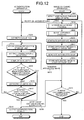
- FIG. 7 is a flowchart illustrating an authenticating process according to the first embodiment. This authenticating process is initiated when the sensor unit 11a detects a user in the viewing area of the television receiver. As illustrated in FIG. 7 , when the sensor unit 11a detects a user in the viewing area (Step S101), the image capturing control unit 11f notifies the authentication apparatus 12 that a user is detected in the viewing area (Step S102).
- the determining unit 12d in the authentication apparatus 12 executes a "divisor determining process" for determining the divisor N by which the exposure time E is divided (Step S103).
- the image capturing instructing unit 12c then sends an image capturing instruction containing image capturing parameters including the divisor N determined by the determining unit 12d to the authentication apparatus 12 (Step S104).
- the image capturing control unit 11f receiving the image capturing instruction then executes an "image capturing process" in which N pieces of OFF images and N pieces of ON images are captured, in the order of N/2 pieces of OFF images, N pieces of ON images, and N/2 pieces of OFF images (Step S105).
- the image capturing control unit 11f then transfers the N pieces of OFF images and the N pieces of ON images to the authentication apparatus 12 via the communicating unit 11d (Step S106).
- the image capturing instructing unit 12c in the authentication apparatus 12 then stores the N pieces of OFF images and the N pieces of ON images in the storage unit 12b (Step S107).
- the computing unit 12e determines N pairs of an OFF image and an ON image, and computes N pieces of difference images from the respective pairs of an OFF image and an ON image (Step S108).
- the computing unit 12e then stores the N pieces of difference images computed at Step S108 in the storage unit 12b (Step S109).
- the integrating unit 12f then generates a single piece of integrated image from the N pieces of difference images, by acquiring the sum of the pixel values across the N pieces of difference images stored in the storage unit 12b (Step S110).
- the integrating unit 12f then stores the integrated image generated at Step S110 in the storage unit 12b (Step S111).
- the authenticating unit 12g then computes a similarity between an image of the authenticated region detected from the integrated image stored in the storage unit 12b at Step S111 and each of the gesture pattern images stored in the storage unit 12b (Step S112).
- the authenticating unit 12g executes the following process. In other words, the authenticating unit 12g outputs a gesture corresponding to the pattern image or a command corresponding to the gesture to the television receiver (Step S114), and the process is ended. If no pattern image has a similarity higher than the predetermined threshold (No at Step S113), the process is ended at this point.
- FIG. 8 is a flowchart illustrating a divisor determining process according to the first embodiment. This process is initiated when the process at Step S102 is executed in the authenticating process illustrated in FIG. 7 , that is, when a notification of a user detection is received from the image capturing apparatus 11.
- the determining unit 12d sets the initial value No preferably applied in an environment without any external light to the divisor N (Step S201).
- the determining unit 12d then sets the unit exposure time E' to E/N computed from the exposure time E and the divisor N (Step S202).
- the determining unit 12d then causes the image capturing apparatus 11 to capture a predetermined number of ON images based on the unit exposure time E' (Step S203).
- the determining unit 12d then computes an external light evaluation value Ex serving as an index for the intensity of external light from the ON images captured at Step S203 (Step S204).
- the determining unit 12d determines if the external light evaluation value Ex is lower than a predetermined threshold Th (Step S205).
- the determining unit 12d updates the divisor N to a value larger than the previous value, e.g., a value twice the previous divisor (Step S206).
- the system control then goes to Step S202, and the determining unit 12d repeats the process of updating the divisor, setting a unit exposure time E', causing the image capturing apparatus 11 to capture ON images, and computing the external light evaluation value Ex, until the external light evaluation value Ex reaches a value lower than the threshold Th.
- the determining unit 12d outputs the divisor N used at Step S201 or Step S206 to the image capturing instructing unit 12c (Step S207), and the process is ended.
- FIG. 9 is a flowchart illustrating an image capturing process according to the first embodiment.
- the image capturing process is initiated when the process at Step S104 is executed in the authenticating process illustrated in FIG. 7 , that is, when an image capturing instruction is received from the authentication apparatus 12.
- the image capturing control unit 11f computes the unit exposure time E' representing an exposure time for a single piece of image, by dividing the exposure time E by the divisor N (Step S301).
- the image capturing control unit 11f then turns OFF the illumination unit 11b, and captures N/2 pieces of OFF images (Step S302).
- the image capturing control unit 11f then turns ON the illumination unit 11b, and captures N pieces of ON images (Step S303).
- the image capturing control unit 11f then turns OFF the illumination unit 11b, and captures N/2 pieces of OFF images (Step S304).
- the image capturing control unit 11f stores the N pieces of OFF images and the N pieces of ON images captured at Steps S302 to S304 in the image storage unit 11e (Step S305), and the process is ended.
- the gesture authentication system 10 according to the first embodiment turns OFF the illumination unit 11b and captures OFF images before and after N pieces of ON images are captured. Therefore, in the gesture authentication system 10 according to the first embodiment, because the frequency at which the illumination is switched from ON to OFF and switched from OFF to ON can be reduced, the frequency of and the time for null write can be reduced. As a result, idle time for capturing images can be reduced. Therefore, the gesture authentication system 10 according to the first embodiment can reduce the image capturing time.
- the authentication apparatus 12 executes the process of capturing ON images and determining the divisor through trial-and-error, the process of computing the difference between an OFF image and an ON image, the process of integrating the difference images, and the like. Therefore, the gesture authentication system 10 according to the first embodiment can simplify the functional configuration of the image capturing apparatus 11. There are more advantageous effects that can be achieved by simplifying the image capturing apparatus 11.
- the authentication apparatus 12 may be built into a fixed place, e.g., near the television receiver or in the television receiver, but the place where the image capturing apparatus 11 is installed may be changed depending on how the image capturing apparatus 11 is used by the user.
- another possible configuration of the system may include one authentication apparatus 12 and a plurality of image capturing apparatuses 11. When such a system configuration is used, the entire cost can be reduced when the configuration of the image capturing apparatus 11 is simplified.
- OFF images that are divided into equal groups are captured before and after the ON images are captured, an ON image and an OFF image at the same order are in the order of the time at which these images are captured, and difference images are computed for each of these pairs. Therefore, for example, the influence of variations such as positional changes, e.g., those of when the hand of the subject gradually moves down, changes in the external light intensity due to a blocking object, and the like can be evenly allocated to the OFF image and the ON image for which a difference is computed. Therefore, difference images that are less affected by such variations can be computed stably.
- the ON images are captured continuously at the center of the image capturing sequence, the influence of the variations in the external light and the subject can be reduced. This is because an ON image has higher luminance, an ON image is more influenced by such variations than an OFF image. Therefore, by capturing the ON images continuously at the center of the image capturing sequence, the influence of such variations can be further reduced.
- the gesture authentication system 10 because an OFF image and an ON image are captured an even number of times, redundant OFF images and ON images not used in computing a difference image are not captured. Therefore, the image capturing time can be reduced.
- the gesture authentication system 10 because the image capturing time is reduced, extension of time in which the images are captured can be suppressed even when used is an image sensor capturing images at a low rate and a long interval. Because an inexpensive image sensor can be used, costs can be reduced.
- the authentication apparatus 12 is caused to generate difference images and an integrated image. However, it is not necessarily need to be the authentication apparatus 12 that generates difference images and an integrated image. Furthermore, explained in the first embodiment is an example in which the image capturing apparatus 11 is caused to capture the images to be used in the gesture authentication, but the image capturing apparatus 11 may also capture images to be used in another type of authentication or determination. Therefore, explained in a second embodiment of the present invention is an example in which an image capturing apparatus 21 is caused to capture OFF images and ON images of the face of a person who is a subject, to generate difference images and an integrated image, and an authentication apparatus 22 is caused to execute a face authentication using the integrated image.
- FIG. 10 is a block diagram illustrating functional configurations of apparatuses included in a face authentication system according to the second embodiment.
- This face authentication system 20 illustrated in FIG. 10 performs a face authentication by matching an integrated image generated from OFF images and ON images in which the face of a person is captured against a registered image that is a pre-registered integrated image of the face of a person based upon which authentication is determined to be successful when the system performs the authentication.
- the face authentication is used in controlling an entry and exit of someone into and from a gate installed in a facility or at the boundary of a room or a booth of a facility.
- the face authentication system 20 includes the image capturing apparatus 21 and the authentication apparatus 22.
- the image capturing apparatus 21 is installed at a position allowing the face of a person passing through a gate to be captured in the angle of view of the image capturing apparatus 21, as an example, so that an image of the face of a person passing through the gate can be captured.
- the authentication apparatus 22 may be implemented as a server connected to a plurality of the image capturing apparatuses 21.
- a function for performing the face authentication may be incorporated into the image capturing apparatus 21 so that face authentication can be performed on standalone basis.
- the image capturing apparatus 21 illustrated in FIG. 10 includes the following functional units, instead of the sensor unit 11a, the illumination unit 11b, the image sensor 11c, the communicating unit 11d, the image storage unit 11e, and the image capturing control unit 11f.
- the image capturing apparatus 21 includes a sensor unit 21a, an illumination unit 21b, an image sensor 21c, a communicating unit 21d, an image storage unit 21e, and an image capturing control unit 21f.
- the sensor unit 21a, the illumination unit 21b, the image sensor 21c, the communicating unit 21d, the image storage unit 21e, the image capturing control unit 21f, a determining unit 21g, a computing unit 21h, and an integrating unit 21j have basic functions that are the same as those of the respective functional units illustrated in FIG. 1 , only the differences are explained hereunder.
- the sensor unit 21a is different from the sensor unit 11a illustrated in FIG. 1 in that the sensor unit 21a detects a user approaching the gate. Therefore, the sensor unit 21a monitors an area where people pass through the gate, e.g., a radius of 1 meter from the gate, as an example. When the sensor unit 21a detects a user passing through such a pass-through area, the sensor unit 21a notifies the image capturing control unit 21f, which will be described later, of entry of the user into the gate pass-through area.
- the illumination unit 21b is different from the illumination unit 11b illustrated in FIG. 1 in that the illumination unit 21b illuminates the face of a user approaching the gate. Therefore, the illumination unit 21b is installed at a position capable of illuminating the authenticated region of the user, e.g., the face of the user, who is in the pass-through area of the gate detected by the sensor unit 21a.
- the illumination unit 21b may also be provided with a mechanical unit for allowing the direction in which the illuminating light is output to be adjusted depending on the position of the user in the pass-through area of the gate.
- the image sensor 21c is different from the image sensor 11c illustrated in FIG. 1 in that the image sensor 21c is installed at a position enabling the face of the user who is in the pass-through area of the gate to be imaged on a lens not illustrated.
- the image sensor 21c may be provided with a mechanical unit for adjusting the angular field of the image capturing apparatus 21 depending on the position where the user is present in the pass-through area of the gate so as to allow the authenticated region of the use to be imaged on the image sensor 21c.
- the image capturing control unit 21f which will be described later, stores the image captured by the image sensor 21c in the image storage unit 21e.
- the communicating unit 21d is different from the communicating unit 11d illustrated in FIG. 1 in that the communicating unit 21d transmits and receives different types of data to and from other apparatuses including the authentication apparatus 22.
- the communicating unit 21d transmits a notification of a user entering the pass-through area of the gate or an integrated image to the authentication apparatus 22.
- the communicating unit 21d also receives an image capturing ending instruction for ending capturing images of the face of the user who have entered the pass-through area of the gate, or a registered image generating instruction for generating a registered image.
- the image storage unit 21e is different from the image storage unit 11e illustrated in FIG. 1 in that the image storage unit 21e stores therein different types of data.
- the image capturing apparatus 21 starts capturing OFF images and ON images, and executes calculations of the difference images and generation of the integrated image. Therefore, in the image storage unit 21e stores therein difference images and an integrated image, in addition to the original images such as OFF images and ON images received from the image sensor 21c.
- the image capturing control unit 21f is different from the image capturing control unit 11f illustrated in FIG. 1 in that the image capturing process is triggered differently.
- the image capturing control unit 21f executes the image capturing process, which is executed by the image capturing control unit 11f illustrated in FIG. 1 , twice, once at a stage registering the face of a person permitted to go through the gate, and another time at a stage generating the face of a user entering gate.
- the image capturing apparatus 21 illustrated in FIG. 10 further includes the determining unit 21g, the computing unit 21h, and the integrating unit 21j, as functional units not illustrated in FIG. 1 .
- the determining unit 21g, the computing unit 21h, and the integrating unit 21j are different from the determining unit 12d, the computing unit 12e, and the integrating unit 12f included in the authentication apparatus 12 illustrated in FIG. 1 in that these functional units are provided to the apparatus capturing images.
- the determining unit 21g, the computing unit 21h, and the integrating unit 21j are different in performing the process at two stages, in the same manner as the process performed by the image capturing control unit 21f.
- the authentication apparatus 22 illustrated in FIG. 10 includes a communicating unit 22a and a storage unit 22b, instead of the communicating unit 12a and the storage unit 12b provided to the authentication apparatus 12 illustrated in FIG. 1 .
- communicating unit 22a and the storage unit 22b have basic functions that are the same as those of the corresponding functional units illustrated in FIG. 1 , only the differences are explained hereunder.
- the communicating unit 22a is different from the communicating unit 12a illustrated in FIG. 1 in that the communicating unit 22a transmits and receives different types of data to and from other apparatuses including the image capturing apparatus 21.
- the communicating unit 22a transmits an image capturing ending instruction and a registered image generating instruction to the image capturing apparatus 21.
- the communicating unit 22a also receives an integrated image and a notification of a user entering the pass-through area of the gate from the image capturing apparatus 21.
- the storage unit 22b is different from the storage unit 12b illustrated in FIG. 1 in that the storage unit 22b stores therein different types of data.
- the image capturing apparatus 21 not only captures OFF images and ON images, but also performs computation of difference images and generation of an integrated image, only the integrated image is stored in the storage unit 22b, without storing therein OFF images, ON images, and difference images.
- the storage unit 22b stores therein a registered image against which the integrated image of the user generated by the image capturing apparatus 21 is compared.
- stored as a registered image is an integrated image of a permitted person who is permitted to make an entry or exit through the gate by the administrator of the face authentication system 20, as well as characterizing quantities extracted from the integrated image.
- stored as a registered image is an integrated image of a permitted person who is permitted to make an entry or exit through the gate by the administrator of the face authentication system 20, as well as characterizing quantities extracted from the integrated image.
- only one of the integrated image or the characterizing quantities of the permitted person may also be stored.
- the authentication apparatus 22 illustrated in FIG. 10 includes a receiving unit 22g, an authenticating unit 22h, and a retry control unit 22j, as functional units not illustrated in FIG. 1 .
- the receiving unit 22g is a processing unit that receives an instruction for generating a registered image.
- various types of user interface such as a keyboard or a touch panel can be used.
- the receiving unit 22g receives an instruction for generating a registered image of a permitted person who is permitted to make an entry or exit through the gate from the administrator of the face authentication system 20, and notifies the image capturing apparatus 21 of the instruction for generating the registered image.
- the image capturing apparatus 21 is caused to capture the OFF images and the ON images of the face of a person whose registered image is to be generated, to compute difference images, and to generate an integrated image.
- the receiving unit 22g may also be independently implemented outside of the authentication apparatus 22.
- the authenticating unit 22h is a processing unit that performs a face authentication of a subject using an integrated image of a user received from the image capturing apparatus 21 and a registered image of a permitted person stored in the storage unit 22b.
- the authenticating unit 22h detects an image of a portion corresponding to the face by executing template matching to an integrated image.
- the authenticating unit 22h extracts geometric characteristics such as the shape or the size of a part of the face, such as eyes, a nose, a mouth, and ears, from the image corresponding to the face portion detected by the template matching as characterizing quantities.
- the authenticating unit 22h then computes a similarity S between each of the registered images stored in the storage unit 22b and characterizing quantities.
- the authenticating unit 22h determines that the authentication is successful if there is any registered image resulting in a similarity S higher than the predetermined threshold. In such a case, it is not necessary to retry the authentication. Therefore, the authenticating unit 22h notifies the image capturing apparatus 21 of an image capturing ending instruction, and outputs a notification of the successful authentication to a device unlocking the door, for example. As a result, the user having entered the pass-through area of the gate is permitted to enter or exit. By contrast, if there is only some registered image resulting in a similarity S less than the predetermined threshold, the authenticating unit 22h determines that the authentication has failed.
- the retry control unit 22j which will be described later, is caused to determine if the authentication has been retried for a certain number of times.
- the threshold compared with the similarity S can be specified in any way. For example, the threshold can be lowered when it is preferable to reduce the false rejection rate, and can be raised when it is preferable to reduce the false acceptance rate.
- the retry control unit 22j is a processing unit that controls retries of the face authentication. As a possible implementation, the retry control unit 22j initializes a retry count R recorded in an internal memory not illustrated to zero when a user entering the pass-through area of the gate is detected. The retry control unit 22j then increments the retry count R when the authenticating unit 22h determines that the authentication has failed, and determines if the retry count R is equal to or higher than the predetermined threshold. If the retry count R is lower than the predetermined threshold, the retry control unit 22j permits an authentication retry.
- the retry control unit 22j causes the authenticating unit 22h to perform a series of the processes including extracting characterizing quantities from an integrated image of the user, computing a similarity with the registered images, and determining if there is any registered image resulting in a similarity equal to or higher than the threshold. If the retry count is equal to or higher than the threshold, the retry control unit 22j does not permit any further retry. In such a case, because it is no longer necessary to generate an integrated image of the user, the retry control unit 22j notifies the image capturing apparatus 21 of an image capturing ending instruction, and outputs a notification of the authentication failure to the image capturing apparatus 21.
- the threshold compared with the retry count R can be specified in any way. For example, the threshold can be raised when it is preferable to reduce the false rejection rate, and can be lowered when it is preferable to reduce the false acceptance rate.
- FIG. 11 is a flowchart illustrating a registration process according to the second embodiment. This registration process is initiated when the authentication apparatus 22 receives an instruction for generating a registered image from the administrator.
- Step S401 when an instruction for generating a registered image is received (Step S401), the receiving unit 22g notifies the image capturing apparatus 21 of the instruction for generating a registered image (Step S402).
- the determining unit 21g in the image capturing apparatus 21 executes the "divisor determining process" for determining the divisor N by which the exposure time E is divided (Step S403).
- the determining unit 21g can execute the same process as that explained in the first embodiment (see FIG. 8 ).
- the image capturing control unit 21f then executes the following process using the image capturing parameters including the divisor N determined by the determining unit 21g.
- the image capturing control unit 21f executes the "image capturing process" in which N pieces of OFF images and N pieces of ON images are captured in the order of N/2 pieces of OFF images, N pieces of ON images, and N/2 pieces of OFF images (Step S404).
- the image capturing control unit 21f can execute the same process as that explained in the first embodiment (see FIG. 9 ).
- the computing unit 21h determines N pairs of an OFF image and an ON image, and computes N pieces of difference images from the respective pairs of an OFF image and an ON image (Step S405).
- the computing unit 21h then stores the N pieces of difference images computed at Step S405 in the image storage unit 21e (Step S406).
- the integrating unit 21j then generates a single piece of integrated image from the N pieces of difference images, by acquiring the sum of the pixel values across the N pieces of difference images stored in the image storage unit 21e (Step S407).
- the integrating unit 21j then stores the integrated image generated at Step S407 in the image storage unit 21e (Step S408).
- the image capturing apparatus 21 then transfers the integrated image to the authentication apparatus 22 via the communicating unit 21d (Step S409).
- the authenticating unit 22h then stores the integrated image in the storage unit 22b as a registered image (Step S410).
- the authenticating unit 22h extracts geometric characteristics such as the shape or the size of a part of the face, e.g., eyes, a nose, a mouth, and ears, from the registered images stored in the storage unit 22b at Step S410 as characterizing quantities (Step S411).
- the authenticating unit 22h then stores the characterizing quantities extracted at Step S411 in the storage unit 22b, in a manner associated with the registered image stored at Step S410 (Step S412), and the process is ended.
- FIG. 12 is a flowchart illustrating an authenticating process according to the second embodiment. This authenticating process is initiated when the sensor unit 21a detects a user entering the pass-through area of the gate.
- Step S601 when the sensor unit 21a detects a user entering the pass-through area of the gate (Step S601), the image capturing control unit 21f notifies the authentication apparatus 22 of the user entering the pass-through area of the gate (Step S602).
- the retry control unit 22j receiving the notification at Step S602 initializes the retry count R by setting the retry count R to zero (Step S603).
- the determining unit 21g in the authentication apparatus 22 then executes the "divisor determining process" for determining the divisor N by which the exposure time E is divided (Step S604).
- the determining unit 21g can execute the same process as that explained in the first embodiment (see FIG. 8 ).
- the image capturing control unit 21f then executes the following process using the image capturing parameters including the divisor N determined by the determining unit 21g.
- the image capturing control unit 21f executes the "image capturing process" in which N pieces of OFF images and N pieces of ON images are captured in the order of N/2 pieces of OFF images, N pieces of ON images, and N/2 pieces of OFF images (Step S605).
- the image capturing control unit 21f can execute the same process as that explained in the first embodiment (see FIG. 9 ).
- the computing unit 21h determines N pairs of an OFF image and an ON image, and computes N pieces of difference images from the respective pairs of an OFF image and an ON image (Step S606).
- the computing unit 21h then stores the N pieces of difference images computed at Step S606 in the image storage unit 21e (Step S607).
- the integrating unit 21j generates a single piece of integrated image from N pieces of difference images, by acquiring the sum of the pixel values across the N pieces of difference images stored in the image storage unit 21e (Step S608).
- the integrating unit 21j then stores the integrated image generated at Step S608 in the image storage unit 21e (Step S609).
- the image capturing apparatus 21 then transfers the integrated image to the authentication apparatus 22 via the communicating unit 21d (Step S610).
- Step S604 to Step S610 The process from Step S604 to Step S610 is repeated until an image capturing ending instruction is received from the authentication apparatus 22 (No at Step S611).
- an image capturing ending instruction is received (Yes at Step S611), the image capturing apparatus 21 ends the process.
- the authentication apparatus 22 stores the integrated image received at Step S610 in the storage unit 22b (Step S612).
- the authenticating unit 22h then extracts characterizing quantities from the integrated image stored in the storage unit 22b at Step S612 (Step S613).
- the authenticating unit 22h then computes a similarity S between the characterizing quantities extracted from the integrated image of the user at Step S613 and the characterizing quantities of each of the registered images stored in the storage unit 22b (Step S614).
- the authenticating unit 22h determines if there is any registered image resulting in a similarity S higher than the predetermined threshold (Step S615). If there is no registered image resulting in a similarity S equal to or higher than the threshold (No at Step S615), the retry control unit 22j increments the retry count R (Step S616), and determines if the retry count R is equal to or higher than the predetermined threshold (Step S617). The authentication apparatus 22 repeats the process from Step S612 to Step S616 until the retry count R reaches a value equal to or higher than the predetermined threshold (No at Step S617).
- the authenticating unit 22h notifies the image capturing apparatus 21 of an image capturing ending instruction (Step S618), outputs the authentication result of successful authentication or authentication failure to the image capturing apparatus 21 and to the unlocking device not illustrated (Step S619), and ends the process.
- the face authentication system 20 according to the second embodiment turns OFF the illumination unit 11b and captures OFF images before and after N pieces of ON images are captured, in the same manner as in the first embodiment described above. Therefore, the face authentication system 20 according to the second embodiment can reduce the frequency at which the illumination is switched from ON to OFF or from OFF to ON, and the frequency of and the time for null write can be reduced. As a result, idle time for capturing images can be reduced. Therefore, in the face authentication system 20 according to the second embodiment as well, the image capturing time can be reduced.
- the image capturing apparatus 21 performs the process of computing the difference between an OFF image and an ON image, the process of integrating the difference images, and the like. Therefore, in the face authentication system 20 according to the second embodiment, only one piece of integrated image can be transferred from the image capturing apparatus 21 to the authentication apparatus 22, without transferring the N pieces of OFF images and the N pieces of ON images. Therefore, the communication traffic between the image capturing apparatus 21 and the authentication apparatus 22 can be reduced. Hence, for example, a communication load on a network connecting the image capturing apparatus 21 and the authentication apparatus 22 can be reduced. As a result, a high speed authenticating process can be realized.
- the image capturing time is reduced, extension in the image capturing time can be suppressed even when used is an image sensor capturing images at a low rate and a long interval. For this reason, because an inexpensive image sensor can be used, costs can be reduced.
- the ON images are captured continuously at the center of the image capturing sequence, the influence of the variations in the external light and the subject can be reduced. This is because an ON image has higher luminance, an ON image is more influenced by such variations than an OFF image. By capturing the ON images continuously at the center of the image capturing sequence, the influence of such variations can be further reduced.
- the face authentication system 20 is used in controlling an entry and exit of user so that the user is permitted or not permitted to make an entry or exit depending on the authentication result output from the authentication apparatus 22.
- the face authentication system 20 may be used for other purposes.
- the face authentication system 20 may also be used in login management in which a login to an information processing apparatus such as a personal computer is permitted or not permitted depending on the authentication result.
- a determination apparatus 32 is caused to determine the material of an object using an integrated image.
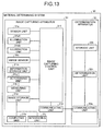
- FIG. 13 is a block diagram illustrating functional configurations of apparatuses included in a material determining system according to the third embodiment.
- a material determining system 30 illustrated in FIG. 13 determines the material of an object by comparing an integrated image of the object generated using an illumination unit 31bA with an integrated image of the object generated using an illumination unit 31bB.
- the material determination is used in determining if an object is made of a material ⁇ or a material ⁇ .
- this material determining system 30 includes an image capturing apparatus 31 and the determination apparatus 32.
- the image capturing apparatus 31 is installed at a position enabling an object whose material is to be determined to be placed in the angle of view of the image capturing apparatus 31 so that images of the object whose material is to be determined can be captured, as an example.
- the determination apparatus 32 may be implemented as a server connected to a plurality of image capturing apparatuses 31, as an example. Alternatively, a function for executing the material determination may be incorporated into the image capturing apparatus 31 so that the material determination is performed on standalone basis.
- the image capturing apparatus 31 illustrated in FIG. 13 includes the following functional units, instead of the sensor unit 21a, the illumination unit 21b, the image sensor 21c, the communicating unit 21d, the image storage unit 21e, the image capturing control unit 21f, the determining unit 21g, the computing unit 21h, and the integrating unit 21j included in the image capturing apparatus 21 illustrated in FIG. 10 .
- the image capturing apparatus 31 includes a sensor unit 31a, the illumination unit 31bA, the illumination unit 31bB, an image sensor 31c, a communicating unit 31d, an image storage unit 31e, an image capturing control unit 31f, a determining unit 31g, a computing unit 31h, and a integrating unit 31j.
- the sensor unit 31a, an illumination unit 31b, the image sensor 31c, the communicating unit 31d, the image storage unit 31e, the image capturing control unit 31f, the determining unit 31g, the computing unit 31h, and the integrating unit 31j have basic functions that are the same as those of the respective functional units illustrated in FIG. 10 . Therefore, only the differences are explained hereunder.
- the sensor unit 31a is different from the sensor unit 21a illustrated in FIG. 10 in that the sensor unit 31a detects an object whose material is to be determined. Therefore, the sensor unit 31a monitors an area in which the object whose material is to be determined is installed, e.g., a radius of 1 meter, from the image capturing apparatus 31. When the sensor unit 31a detects any object in such an installation area, the sensor unit 31a notifies the image capturing control unit 31f, which will be described later, that an object is installed in the installation area.
- the illumination unit 31bA is different from the illumination unit 21b illustrated in FIG. 10 in that the illumination unit 31bA illuminates the object whose material is to be determined. Therefore, the illumination unit 31bA is installed at a position for illuminating the central portion of a region to be determined of the object that is installed in the installation area detected by the sensor unit 31a, for example.
- the illumination unit 31bA may be provided with a mechanical unit for allowing the direction to which the illuminating light is output to be adjusted depending on the position of an object in the installation area. In the description hereunder, it is assumed that the illumination unit 31bA uses an illumination A with a wavelength at ⁇ A as a light source.
- the illumination unit 31bB is different from the illumination unit 31bA in that the wavelength of the light source is longer than that of the illumination unit 31bA.
- the illumination unit 31bB uses an illumination B having a wavelength at ⁇ B that is longer than ⁇ A as a light source.
- the image sensor 31c is different from the image sensor 21c illustrated in FIG. 10 in that the image sensor 31c is installed at a position where the object in the installation area is allowed to be imaged on the image sensor 21c via a lens not illustrated.
- the image sensor 31c may also include a mechanical unit for adjusting the angular field of the image capturing apparatus 31 depending on the position of the object in the installation area so that the region to be determined of the object can be imaged on the image sensor 31c.
- the image capturing control unit 31f which will be described later, stores the images captured by the image sensor 31c in the image storage unit 31e.
- the communicating unit 31d is different from the communicating unit 21d illustrated in FIG. 10 in that the communicating unit 31d transmits and receives different types of data to and from other apparatuses including the determination apparatus 32.
- the communicating unit 31d transfers an integrated image for the illumination unit 31bA and an integrated image for the illumination unit 31bB both of which are generated by the integrating unit 31j to be described later to the determination apparatus 32.
- the image storage unit 31e stores therein different types of data from those stored in the image storage unit 21e illustrated in FIG. 10 .
- the image capturing apparatus 31 captures the OFF images and the ON images using the illumination units 31bA and 31bB, computes difference images, and generates an integrated image. Therefore, the image storage unit 31e stores therein original images such as OFF images and ON images for the illumination units 31bA and 31bB acquired from the image sensor 31c, difference images, and an integrated image.
- the image capturing control unit 31f is different from the image capturing control unit 21f illustrated in FIG. 10 in that image capturing control unit 31f captures not only ON images with the illumination unit 31bA but also ON images with the illumination unit 31bB.
- the image capturing control unit 31f turns ON the illumination unit 31bA and turns OFF the illumination unit 31bB, and captures N pieces of ON images with the illumination unit 31bA before and after turning OFF the illumination unit 31bA, turning ON the illumination unit 31bB, and capturing N pieces if ON images with the illumination unit 31bB.
- the image capturing control unit 31f also turns OFF the illumination unit 31bA and the illumination unit 31bB, and captures 2*N pieces of OFF images before and after turning ON the illumination unit 31bA, turning OFF the illumination unit 31bB, and capturing N pieces of ON images with the illumination unit 31bA.
- the image capturing control unit 31f turns ON the illumination unit 31bA and captures N/2 pieces of ON images with the illumination unit 31bA.
- the image capturing control unit 31f then turns OFF the illumination unit 31bA and turns ON the illumination unit 31bB, and captures N pieces of ON images with the illumination unit 31bB.
- the image capturing control unit 31f then turns OFF the illumination unit 31bB, turns ON the illumination unit 31bA, and captures N/2 pieces of ON images with the illumination unit 31bA, and then turns OFF the illumination unit 31bA and the illumination unit 31bB and captures N pieces of OFF images.
- FIG. 14 is a schematic of an example of the image capturing sequence. Illustrated as an example in FIG. 14 is an image capturing sequence of when the divisor N is "4". As illustrated in FIG. 14 , the image capturing control unit 31f keeps the illumination unit 31bA and the illumination unit 31bB OFF for a period from time H0 to time H4, and closes the shutter temporarily at time H1, time H2, and time H3.
- the image capturing control unit 31f stores an OFF image aA1 acquired through the exposure over a period from "H0 to H1", an OFF image aA2 acquired through the exposure over a period from "H1 to H2", an OFF image aB1 acquired through the exposure over a period from "H2 to H3”, and an OFF image aB2 acquired through the exposure over a period from "H3 to H4" in the image storage unit 31e in the order described herein.
- the image capturing control unit 31f then switches the illumination unit 31bA from OFF to ON at time H4.
- the image capturing control unit 31f performs null write to the image storage unit 31e for an image acquired through the exposure over a period "H4 to H5", assuming that switching from OFF to ON takes time from time H4 to time H5.
- the image capturing control unit 31f keeps the illumination unit 31bA ON for a period from time H5 to time H7, closes the shutter temporarily at time H6.
- an ON image bA1 acquired through the exposure over a period from "H5 to H6” and an ON image bA2 acquired through the exposure over a period from "H6 to H7" are stored in the image storage unit 31e in the order described herein.
- the image capturing control unit 31f then switches the illumination unit 31bA from ON to OFF at time H7, and switches the illumination unit B from OFF to ON.
- the image capturing control unit 31f then performs null write to the image storage unit 31e for an image acquired through the exposure over a period "H7 to H8".
- the image capturing control unit 31f then keeps the illumination unit 31bB ON for a period from time H8 to time H12, and closes the shutter temporarily at time H9, time H10, and time H11.
- the image capturing control unit 31f causes the image storage unit 31e to store therein an ON image bB1 acquired through the exposure over a period from "H8 to H9", an ON image bB2 acquired through the exposure over a period from "H9 to H10", an ON image bB3 acquired through the exposure over a period from "H10 to H11”, and an ON image bB4 acquired through the exposure over a period from "H11 to H12" in the order described herein.
- the image capturing control unit 31f then switches the illumination unit 31bA from OFF to ON, and switches the illumination unit B from ON to OFF at time H12.
- the image capturing control unit 31f then performs null write to the image storage unit 31e for an image acquired through the exposure over a period "H12 to H13".
- the image capturing control unit 31f then keeps the illumination unit 31bA ON for a period from time H13 to time H15, and closes the shutter temporarily at time H14.
- an ON image bA3 acquired through the exposure over a period from "H13 to H14” and an ON image bA4 acquired through the exposure over a period from "H14 to H15" are stored in the image storage unit 31e in the order described herein.
- the image capturing control unit 31f then switches the illumination unit 31bA from ON to OFF at time H15.
- the image capturing control unit 31f then performs null write to the image storage unit 31e for an image acquired through the exposure over a period "H15 to H16".
- the image capturing control unit 31f then keeps the illumination unit 31bA and the illumination unit 31bB OFF for a period from time H16 to time H20, and closes the shutter temporarily at time H17, time H18, and time H19.
- the image capturing control unit 31f causes the image storage unit 31e to store therein an OFF image aB3 acquired through the exposure over a period from "H16 to H17", an OFF image aB4 acquired through the exposure over a period from "H17 to H18", an OFF image aA3 acquired through the exposure over a period from "H18 to H19”, and an OFF image aA4 acquired through the exposure over a period from "H19 to H20" in the order described herein.
- the determining unit 31g is different from the determining unit 21g illustrated in FIG. 10 in that the determining unit 31g determines the divisor using information in which the intensity of the external light is associated with a divisor.
- the determining unit 31g determines the divisor N using information in which an output current is associated with a divisor. This information serves as an index for the intensity of external light, and is stored in an information storage unit 31m which is to be described later.
- FIG. 15 is a schematic of an example of information in which an output current is associated with a divisor. For example, when an output current measured with a measuring unit 31k to be described later is 35 milliamperes, the determining unit 31g determines "4" as the divisor N.
- the determining unit 31g determines the divisor N using an illumination whose optimal exposure time is the longest. For example, when the optimal exposure time with the light from the illumination unit 31bB is longer than that with the illumination unit 31bA, the determining unit 31g causes the measuring unit 31k to measure the output current using the light of the illumination unit 31bB, and determines the divisor N. An image capturing instruction containing the divisor N thus determined and the exposure time E is then output to the image capturing control unit 11f.
- the computing unit 31h is different from the computing unit 21h illustrated in FIG. 10 in that the computing unit 31h computes difference images for each of the illumination unit 31bA and the illumination unit 31bB. Therefore, in the example illustrated in FIG. 14 , the computing unit 31h establishes four pairs by pairing the OFF image aA1 and the ON image bA1, pairing the OFF image aA2 and the ON image bA2, pairing the OFF image aA3 and the ON image bA3, and pairing the OFF image aA4 and the ON image bA4. The computing unit 31h then computes a difference image A1 for the illumination unit 31bA by computing pixel value differences between the pixels in the OFF image aA1 and those in the ON image bA1.
- the computing unit 31h computes a difference image A2 from the OFF image aA2 and the ON image bA2, computes a difference image A3 from the OFF image aA3 and the ON image bA3, and computes a difference image A4 from the OFF image aA4 and the ON image bA4.
- the computing unit 31h also establishes four pairs by paring the OFF image aB1 and the ON image bB1, paring the OFF image aB2 and the ON image bB2, paring the OFF image aB3 and the ON image bB3, and paring the OFF image aB4 and the ON image bB4.
- the computing unit 31h computes a difference image B1 for the illumination unit 31bB by computing pixel value differences between the pixels in the OFF image aB1 and those in the ON image bB1.
- the computing unit 31h computes a difference image B2 from the OFF image aB2 and the ON image bB2, computes a difference image B3 from the OFF image aB3 and the ON image bB3, and computes a difference image B4 from the OFF image aB4 and the ON image bB4.
- the computing unit 31h computes N pieces of difference images for the illumination unit 31bA and N pieces of difference images for the illumination unit 31bB.
- the computing unit 31h then stores N pieces of difference images for the illumination unit 31bA and those for the illumination unit 31bB in an image storage unit 31e.
- the integrating unit 31j is different from the integrating unit 31j illustrated in FIG. 10 in that the integrating unit 31j generates an integrated image for each of the illumination unit 31bA and the illumination unit 31bB.
- the image capturing apparatus 31 also includes the measuring unit 31k and the information storage unit 31m.
- the measuring unit 31k is a processing unit that measures the intensity of external light.
- the measuring unit 31k measures an output current acquired by the generation of an electromotive force resulting from the photovoltaic effect achieved when the measuring unit 31k is illuminated with the light from the illumination, as an index of the external light intensity.
- the optimal exposure time differs depending on the illumination, because the light intensity of the illumination and the sensitivity of the image sensor vary depending on the wavelength of the illumination. Furthermore, saturation is more likely to be produced from an illumination with a long optimal exposure time than one with a short optimal exposure time.
- the measuring unit 31k sets the wavelength of the light to be measured to the wavelength of the light whose optimal exposure time is the longest.
- An example of a possible implementation of the measuring unit 31k includes a detector such as a photodiode or a phototransistor.
- the information storage unit 31m is a storage device storing therein information in which an intensity of the external light is associated with a divisor.
- the information storage unit 31m stores therein information in which an output current measured with the measuring unit 31k is associated with a divisor in advance.
- values acquired through experiments or the like are set in advance.
- this information is information having a table format in which a divisor corresponding to an output current range is set in the same row as the output current range.
- the information storage unit 31m is accessed, when an output current is measured with the measuring unit 31k, to read the information of the divisor corresponding to the output current thus measured.
- the determination apparatus 32 illustrated in FIG. 13 includes a communicating unit 32a and a storage unit 32b, instead of the communicating unit 22a, and the storage unit 22b included in the authentication apparatus 22 illustrated in FIG. 10 .
- communicating unit 32a and the storage unit 32b have basic functions that are the same as those of the respective functional units illustrated in FIG. 10 , only the differences are explained hereunder.
- the communicating unit 32a transmits and receives different types of data to and from other apparatuses including the image capturing apparatus 31, from those transmitted and received by the communicating unit 22a illustrated in FIG. 10 .
- the communicating unit 32a receives an integrated image for the illumination unit 31bA and an integrated image for the illumination unit 31bB from the image capturing apparatus 31.
- the storage unit 32b stores therein different types of data from those stored in the storage unit 22b illustrated in FIG. 10 .
- the image capturing apparatus 31 transfers an integrated image for the illumination unit 31bA and the integrated image for the illumination unit 31bB to the determination apparatus 32. Therefore, as an example, when the integrated image for the illumination unit 31bA and the integrated image for the illumination unit 31bB are received from the image capturing apparatus 31, the storage unit 32b stores therein the integrated image for the illumination unit 31bA and the integrated image for the illumination unit 31bB.
- the storage unit 32b is accessed by a determination unit 32c, which will be described later, making a reference to the integrated image for the illumination unit 31bA and the integrated image for the illumination unit 31bB.
- the determination apparatus 32 further includes the determination unit 32c.
- the determination unit 32c is a processing unit that determines the material of an object, using the integrated images generated by the image capturing apparatus 31. As a possible implementation, the determination unit 32c determines the material of an object by computing luminance ratio between the luminance in an image A that is an integrated image for the illumination unit 31bA and that in an image B that is an integrated image for the illumination unit 31bB.
- FIG. 16 is a graph illustrating an example of a relation between a wavelength and reflectance of different materials. As illustrated in FIG. 16 , reflectance of a material differs depending on the wavelength of the illuminating light.
- the material of an object can be determined by comparing the luminance in an image captured when the object is illuminated with the light from the illumination unit 31bA at a wavelength ⁇ A and another image captured when the object is illuminated with the illumination unit 31bB at a wavelength ⁇ B .
- the determination unit 32c sets a determined area D to the integrated images generated by the image capturing apparatus 31.
- the determination unit 32c determines if the luminance ratio R(x, y) between the image A and the image B thus computed is lower than the predetermined threshold. If R(x, y) is lower than the predetermined threshold, the determination unit 32c determines that the object is made of material ⁇ . If R(x, y) is equal to or higher than the predetermined threshold, the determination unit 32c determines that the object is made of material ⁇ .
- FIG. 17 is a flowchart illustrating the determining process according to the third embodiment.
- the determining process is initiated when the sensor unit 31a detects an object in the installation area.
- the determining unit 31g executes the "divisor determining process" for determining the divisor N by which the exposure time E is divided (Step S802).
- the image capturing control unit 31f captures N pieces of OFF images, N/2 pieces of ON images with the illumination unit 31bA, and N pieces of ON images with the illumination unit 31bB in the order described herein, based on the image capturing instruction containing image capturing parameters including the divisor N determined by the determining unit 31g.
- the image capturing control unit 31f then captures N/2 pieces of ON images with the illumination unit 31bA and N pieces of OFF images in the order described herein. In this manner, the image capturing control unit 31f performs the "image capturing process" in which 2*N pieces of OFF images, N pieces of ON images with the illumination unit 31bA, and N pieces of ON images with the illumination unit 31bB are captured (Step S803).
- the computing unit 31h determines N pairs of an OFF image and an ON image with the illumination unit 31bA, and N pairs of an OFF image and an ON image with the illumination unit 31bB.
- the computing unit 31h then computes N pieces of difference images from the respective pairs of an OFF image and an ON image for each of the illumination unit 31bA and the illumination unit 31bB (Step S804).
- the computing unit 31h stores the N pieces of difference images for each of the illumination unit 31bA and the illumination unit 31bB computed at Step S804 in the image storage unit 31e (Step S805).
- the integrating unit 31j then acquires the sum of the pixel values across the N pieces of difference images for each of the illumination unit 31bA and the illumination unit 31bB, stored in the image storage unit 31e. In this manner, the integrating unit 31j generates a single piece of integrated image for the illumination unit 31bA and a single piece of integrated image for the illumination unit 31bB, from the N pieces of difference images for the illumination unit 31bA and the N pieces of difference images for the illumination unit 31bB, respectively (Step S806). The integrating unit 31j then stores the integrated images generated at Step S806 in the image storage unit 31e (Step S807). The image capturing apparatus 31 transfers the integrated image for the illumination unit 31bA and the integrated image for the illumination unit 31bB to the determination apparatus 32 via the communicating unit 31d (Step S808).
- the determination apparatus 32 stores the integrated image for the illumination unit 31bA and the integrated image for the illumination unit 31bB in the storage unit 32b (Step S809).
- the determination unit 32c then computes a luminance ratio R from the integrated image for the illumination unit 31bA and the integrated image for the illumination unit 31bB stored at Step S809 in the storage unit 32b (Step S810).
- the determination unit 32c determines that the object is made of a material ⁇ (Step S812), and the process is ended. If the luminance ratio R is lower than the predetermined threshold (No at Step S811), the determination unit 32c determines that the object is made of a material ⁇ (Step S813), and the process is ended.
- FIG. 18 is a flowchart illustrating a divisor determining process according to the third embodiment. This process is initiated when the process at Step S801 is executed in the determining process illustrated in FIG. 17 , in other words, when the sensor unit 31a detects an object.
- the measuring unit 31k measures the output current (Step S901).
- the determining unit 31g determines the divisor N from the output current measured with the measuring unit by referring to the associating information that is the information in which an output current is associated with a divisor (Step S902).
- the determining unit 31g then outputs an image capturing instruction containing the divisor N thus determined to the image capturing control unit 31f (Step S903), and the process is ended.
- FIG. 19 is a flowchart illustrating the image capturing process according to the third embodiment. This image capturing process is initiated when an image capturing instruction is received from the determining unit 31g.
- the image capturing control unit 31f computes the unit exposure time E' representing an exposure time for a single piece of image, by dividing the exposure time E by the divisor N (Step S1001).
- the image capturing control unit 31f then turns OFF the illumination unit 31bA and the illumination unit 31bB, and captures N pieces of OFF images (Step S1002).
- the image capturing control unit 31f then turns ON the illumination unit 31bA, keeps the illumination unit 31bB OFF, and captures N/2 pieces of ON images with the illumination unit 31bA (Step S1003).
- the image capturing control unit 31f then turns OFF the illumination unit 31bA, turns ON the illumination unit 31bB, and captures N pieces of ON images with the illumination unit 31bB (Step S1004).
- the image capturing control unit 31f then turns ON the illumination unit 31bA, turns OFF the illumination unit 31bB, and captures N/2 pieces of ON images with the illumination unit 31bA (Step S1005).
- the image capturing control unit 31f then turns OFF the illumination unit 31bA and the illumination unit 31bB, and captures N pieces of OFF images (Step S1006).
- the image capturing control unit 31f stores the N pieces of OFF images, the N pieces of ON images with the illumination unit 31bA, and the N pieces of ON images with the illumination unit 31bB acquired through the process at Step S1002 to Step S1006 in the image storage unit 31e (Step S1007), and the process is ended.
- the material determining system 30 according to the third embodiment captures OFF images before and after capturing the ON images. Because the material determining system 30 according to the third embodiment can reduce the frequency at which the illumination is switched from ON to OFF or from OFF to ON, the frequency of and the time for null write can be reduced. As a result, idle time for capturing images can be reduced. Hence, the material determining system 30 according to the third embodiment can reduce the image capturing time.
- the material determining system 30 according to the third embodiment determines the divisor using an apparatus for measuring an output current and information in which an output current is associated with a divisor. Therefore, with the material determining system 30 according to the third embodiment, because the process for determining the divisor can be simplified, the image capturing time can be reduced. As an example, because capturing of ON images for determining the divisor and the computation of the external light evaluation value can be omitted, the image capturing time can be reduced. As another example, because when the external light is lower than the predetermined threshold, the process of computing the difference images and the process of generating the integrated image can be omitted by setting the divisor to zero, the image capturing time can be reduced.
- the material determining system 30 because the image capturing time is reduced, extension in the image capturing time can be suppressed, even when used is an image sensor capturing images at a low rate and a long interval. Because an inexpensive image sensor can be used, costs can be reduced.
- the ON images are captured continuously at the center of the image capturing sequence, the influence of the variations in the external light and the subject can be reduced. This is because an ON image has higher luminance, an ON image is more influenced by such variations than an OFF image. By capturing the ON images continuously at the center of the image capturing sequence, the influence of such variations can be further reduced.
- the material determining system 30 determines the divisor based on an illumination whose optimal exposure time is the longest, saturation can be suppressed. Therefore, the determination accuracy can be improved.
- capturing of images with the illumination whose optimal exposure time is the longest is positioned at the center of the image capturing sequence.
- the influence of variations such as positional changes in the object or changes in the external light intensity can be reduced.
- the authenticated region is not limited to a face, but other biometric information such as a fingerprint or a palm vein may be used.
- a palm that is the subject is irradiated with an illumination having a high transmittance to a human body, and an image capturing apparatus is caused to capture a reflected light.
- the person is then authenticated using a subdermal vein pattern captured by the image capturing apparatus as characteristics to be authenticated. Because a palm vein authentication uses a vein pattern that is usually invisible to human eyes in the authentication, the risk of leakage of characteristics to be authenticated is low.
- a palm vein authentication can be used as a personal authentication technology mainly in high-security fields, such as in a bank automatic tellers machine (ATM). Furthermore, because a palm vein authentication is a non-contact authentication not allowing the subject to touch the sensor, the user is forced to hold his/her hand over the sensor for a longer time when the image capturing time is extended. Therefore, the convenience can be improved by reducing the image capturing time.
- ATM bank automatic tellers machine
- the process of generating the difference image may be initiated once a single piece of OFF image and a single piece of ON image are generated, and the process of integrating the difference images for generating an integrated image may be initiated sequentially every time two pieces of difference images are generated. In this manner, generation of the OFF image and the ON image, generation of the difference image, and generation of the integrated image can be performed in parallel, without waiting for each of these processes of image generation to be completed. In this manner, the image capturing time can be reduced.
- the divisor Used in the example explained in the first to the third embodiments is an approach in which the divisor is determined by capturing ON images for determining the divisor, in addition to the ON images used in computing difference images.
- the ON images used in computing the difference images may also be used in determining the divisor.
- the N pieces of ON images captured after the N/2 pieces of OFF images are captured may be used as the ON images for determining the divisor.
- FIG. 20 is a flowchart illustrating an example of such a divisor determining process.
- the divisor determining process illustrated in FIG. 20 is initiated when a user is detected in the pass-through area of the gate, as illustrated in FIG. 12 .
- the determining unit 21g sets the initial value No to the divisor N (Step S701).
- the determining unit 21g then sets the unit exposure time E' to E/N that is computed from the exposure time E and the divisor N (Step S702).
- the determining unit 21g then causes the image capturing control unit 21f to capture N/2 pieces of OFF images based on the unit exposure time E' (Step S703).
- the determining unit 21g then causes the image capturing control unit 21f to capture N pieces of ON images (Step S704).
- the determining unit 21g computes the external light evaluation value Ex from the ON images captured at Step S704 (Step S705).
- the determining unit 21g determines if the external light evaluation value Ex is lower than predetermined threshold Th (Step S706).
- the determining unit 21g updates the divisor N to a value larger than the previous value, e.g., a value twice the previous divisor (Step S707).
- the system control then goes to Step S702, and the determining unit 21g repeats the process of updating the divisor, setting a unit exposure time E', capturing OFF images, capturing ON images, and computing the external light evaluation value Ex, until the external light evaluation value Ex reaches a value lower than the threshold Th.
- the determining unit 21g outputs the divisor N used at Step S701 or at Step S707 to the image capturing control unit 21f (Step S708), and the process is ended.
- the image capturing apparatus 21 performs the process at Step S605 and thereafter illustrated in FIG. 12 .
- the divisor is determined using the N pieces of ON images captured by the image capturing control unit 21f used in computing difference images, capturing of ON images for determining the divisor, which are images not used in computing difference images, is not required. Therefore, the number of times the ON images are captured is reduced. Thus, the image capturing time can be reduced.
- FIG. 21 is a schematic of an example of such an image capturing sequence. Illustrated in FIG. 21 is an example of an image capturing sequence in which images are captured repeatedly when the divisor N is "4". Explained hereunder is an example in which the continuous capturing is applied to the second embodiment. As illustrated in FIG. 21 , the image capturing control unit 21f keeps the illumination unit 21b OFF during a period from time M0 to time M2, and closes the shutter temporarily at time M1.
- the image capturing control unit 21f then causes the image storage unit 21e to store therein an OFF image c1 acquired through the exposure over a period from "M0 to M1", and causes the image storage unit 21e to store therein an OFF image c2 acquired through the exposure over a period "M1 to M2".
- the image capturing control unit 21f then switches the illumination unit 21b from OFF to ON at time M2. At this time, certain time is taken to complete switching from OFF to ON. Therefore, assuming that switching from OFF to ON takes time from time M2 to time M3, the image capturing control unit 21f performs null write to the image storage unit 21e for an image acquired through the exposure over a period "M2 to M3". Null is thus stored because any image acquired before switching to ON or OFF is completed is not used in the authentication.
- the image capturing control unit 21f then keeps the illumination unit ON for a period from time M3 to time M7, and closes the shutter temporarily at time M4, time M5, and time M6.
- the ON image d1 acquired through the exposure over a period from "M3 to M4", the ON image d2 acquired through the exposure over a period from "M4 to M5", the ON image d3 acquired through the exposure over a period from "M5 to M6", and the ON image d4 acquired through the exposure over a period from "M6 to M7" are stored in the image storage unit 21e in the order described herein.
- the image capturing control unit 21f switches the illumination unit 21b from ON to OFF at time M7.
- the image capturing control unit 21f performs null write to the image storage unit 21e for an image acquired through the exposure over a period from "M7 to M8".
- the image capturing control unit 21f keeps the illumination unit 21b OFF for a period from time M8 to time M10, and closes the shutter temporarily at time M9 and time M10.
- the image capturing control unit 21f causes the image storage unit 21e to store therein an OFF image c4 acquired through the exposure over a period "M9 to M10". This process is repeated until an image capturing ending instruction is received.
- the image capturing control unit 21f instructs the computing unit 21h, which will be described later, to compute difference images.
- the continuous capturing is applied to the second embodiment.
- the continuous capturing may be applied to the first embodiment or the third embodiment, without limitation to the second embodiment.
- the computing unit may compute the current difference image using the OFF image used in computing the previous difference image or to be used in computing the subsequent difference image.
- the computing unit may compute the difference images by pairing these ON images with the OFF images c3 to c6 (the alternative 1 in FIG. 21 ), with the OFF images c4 to c7 (the alternative 2 in FIG. 21 ), with the OFF images c5 to c8 (the alternative 3 in FIG. 21 ), or with the OFF images c6 to c9 (the alternative 4 in FIG. 21 ).
- the alternative 2 in FIG. 21 the alternative 2 in FIG.
- the computing unit establishes four pairs by pairing the OFF image c4 and the ON image d5, pairing the OFF image c5 and the ON image d6, pairing the OFF image c6 and the ON image d7, and pairing the OFF image c7 and the ON image d8.
- the computing unit then computes a difference image cd1 by computing pixel value differences between the pixels in the OFF image c4 and those in the ON image d5.
- the computing unit computes a difference image cd2 from the OFF image c5 and the ON image d6, computes a difference image cd3 from the OFF image c6 and the ON image d7, and computes a difference image cd4 from the OFF image c7 and the ON image d8.
- an ON image can be paired with an OFF image captured under similar conditions as those under which the ON image is captured. In this manner, the influence of positional changes in the subject or changes in the external light intensity can be reduced.
- an illumination with a different distribution profile may be used.
- an illumination provided with a lens may be used so that the subject is irradiated with a spot light converged by the lens.
- Use of a spot light for irradiating the subject enables the distance to the subject to be measured. Therefore, the determination accuracy can be improved.
- FIG. 22 is a schematic for explaining an example of a computer for executing an image capturing program according to the first to the third embodiments.
- this computer 100 includes an operation unit 110a, a speaker 110b, a camera 110c, a display 120, and a communicating unit 130.
- the computer 100 also includes a CPU 150, a read-only memory (ROM) 160, a hard-disk drive (HDD) 170, and a random access memory (RAM) 180. These units are connected via a bus 140.
- ROM read-only memory
- HDD hard-disk drive
- RAM random access memory
- An image capturing program 170a achieving the same functions as those of the image capturing control unit 11f, the determining unit 12d, the computing unit 12e, the integrating unit 12f, and the authenticating unit 12g described in the first embodiment is stored in advance in the HDD 170, as illustrated in FIG. 22 .
- the functions achieved by the image capturing program 170a may be integrated or separated as appropriate, in the same manner as each of the image capturing control unit 11f, the determining unit 12d, the computing unit 12e, the integrating unit 12f and the authenticating unit 12g illustrated in FIG. 1 .
- the functions achieved by the image capturing program 170a may be integrated or separated as appropriate, in the same manner as the image capturing control unit 21f, the determining unit 21g, the computing unit 21h, the integrating unit 21j, and the authenticating unit 22h illustrated in FIG. 10 . Furthermore, the functions achieved by the image capturing program 170a may be integrated or separated as appropriate, in the same manner as the image capturing control unit 31f, the determining unit 31g, the computing unit 31h, the integrating unit 31j, and the determination unit 32c illustrated in FIG. 13 . In other words, all data to be stored in the HDD 170 does not always need to be stored in the HDD 170, and only data to be used for the processes may be stored in the HDD 170.
- the CPU 150 then reads the image capturing program 170a from the HDD 170, and loads the program onto the RAM 180. In this manner, the image capturing program 170a functions as an image capturing process 180a, as illustrated in FIG. 22 .
- the image capturing process 180a loads various types of data read from the HDD 170 onto an area assigned to the image capturing process 180a on the RAM 180, and executes various processes based on such data thus loaded.
- the image capturing process 180a includes the processes executed by the image capturing control unit 11f, the determining unit 12d, the computing unit 12e, the integrating unit 12f, and the authenticating unit 12g illustrated in FIG. 1 , e.g., the process illustrated in FIG. 7 .
- the image capturing process 180a also includes the process executed by the image capturing control unit 21f, the determining unit 21g, the computing unit 21h, the integrating unit 21j, and the authenticating unit 22h illustrated in FIG. 10 , e.g., the process illustrated in FIG. 12 .
- the image capturing process 180a also includes the process executed by the image capturing control unit 31f, the determining unit 31g, the computing unit 31h, the integrating unit 31j, and the determination unit 32c illustrated in FIG. 13 , e.g., the process illustrated in FIG. 17 .
- Not all of the processing units that are virtually realized on the CPU 150 do not always need to be operating on the CPU 150, and only the processing units to be used for the process may be virtually realized on the CPU 150.
- the image capturing program 170a does not necessarily need to be stored in the HDD 170 or in the ROM 160 in advance.
- each of these computer programs may be stored in a "portable physical medium" inserted into the computer 100 such as a flexible disk (FD), a compact disk read-only memory (CD-ROM), a digital versatile disk (DVD), a magneto-optical disk, or an integrated circuit (IC) card, and the computer 100 then may acquire each of the computer programs from the portable physical medium, and execute the computer program.
- FD flexible disk
- CD-ROM compact disk read-only memory
- DVD digital versatile disk
- IC integrated circuit
- each of the computer programs may be stored in another computer or a server connected to the computer 100 over a public circuit, the Internet, a local area network (LAN), or a wide area network (WAN), and the computer 100 may acquire each of the computer programs from the computer or the server, and execute the computer program.
- a public circuit the Internet
- LAN local area network
- WAN wide area network
- An embodiment of the present invention can reduce an image capturing time.
Landscapes
- Engineering & Computer Science (AREA)
- Multimedia (AREA)
- Signal Processing (AREA)
- Studio Devices (AREA)
- General Physics & Mathematics (AREA)
- Physics & Mathematics (AREA)
- Image Input (AREA)
- Collating Specific Patterns (AREA)
- Stroboscope Apparatuses (AREA)
- Transforming Light Signals Into Electric Signals (AREA)
- Measurement Of The Respiration, Hearing Ability, Form, And Blood Characteristics Of Living Organisms (AREA)
- Measuring And Recording Apparatus For Diagnosis (AREA)
- Apparatus For Radiation Diagnosis (AREA)
Applications Claiming Priority (1)
| Application Number | Priority Date | Filing Date | Title |
|---|---|---|---|
| JP2013012688A JP5974913B2 (ja) | 2013-01-25 | 2013-01-25 | 撮像方法、撮像装置及び撮像プログラム |
Publications (3)
| Publication Number | Publication Date |
|---|---|
| EP2760192A2 true EP2760192A2 (fr) | 2014-07-30 |
| EP2760192A3 EP2760192A3 (fr) | 2017-10-25 |
| EP2760192B1 EP2760192B1 (fr) | 2018-11-28 |
Family
ID=49841497
Family Applications (1)
| Application Number | Title | Priority Date | Filing Date |
|---|---|---|---|
| EP13196877.8A Not-in-force EP2760192B1 (fr) | 2013-01-25 | 2013-12-12 | Appareil et procédé de capture d'image |
Country Status (5)
| Country | Link |
|---|---|
| US (1) | US9100582B2 (fr) |
| EP (1) | EP2760192B1 (fr) |
| JP (1) | JP5974913B2 (fr) |
| KR (1) | KR101559630B1 (fr) |
| CN (1) | CN103973964B (fr) |
Families Citing this family (11)
| Publication number | Priority date | Publication date | Assignee | Title |
|---|---|---|---|---|
| CN104144520A (zh) | 2013-05-07 | 2014-11-12 | 李东舸 | 一种设备间建立连接的方法、装置与系统 |
| CN104143074A (zh) * | 2013-05-07 | 2014-11-12 | 李东舸 | 一种用于基于运动特征信息生成运动特征码的方法和设备 |
| SE1650750A1 (en) * | 2016-05-30 | 2017-12-01 | Fingerprint Cards Ab | Fingerprint sensor with force sensor |
| JP6917761B2 (ja) * | 2017-05-09 | 2021-08-11 | 株式会社キーエンス | 画像検査装置 |
| JP7210872B2 (ja) * | 2017-07-19 | 2023-01-24 | 富士フイルムビジネスイノベーション株式会社 | 画像処理装置及び画像処理プログラム |
| JP6266833B1 (ja) | 2017-07-28 | 2018-01-24 | 京セラ株式会社 | 電子機器、プログラムおよび制御方法 |
| JP7052256B2 (ja) | 2017-08-25 | 2022-04-12 | 富士通株式会社 | 画像処理装置、画像処理方法、及び画像処理プログラム |
| JP2019028973A (ja) * | 2017-12-20 | 2019-02-21 | 京セラ株式会社 | 電子機器、プログラムおよび制御方法 |
| JP6627894B2 (ja) * | 2018-01-12 | 2020-01-08 | 日本電気株式会社 | 顔認証装置 |
| JP6564483B1 (ja) * | 2018-03-15 | 2019-08-21 | 株式会社日本総合研究所 | 照明制御システム、照明システム、作業機械、及びプログラム |
| CN119729223A (zh) * | 2024-12-23 | 2025-03-28 | 福州大学 | 一种保持成像光照一致的摄像系统及其工作方法 |
Citations (1)
| Publication number | Priority date | Publication date | Assignee | Title |
|---|---|---|---|---|
| JP2008090412A (ja) | 2006-09-29 | 2008-04-17 | Fujitsu Ltd | 画像生成装置、画像生成方法および画像生成プログラム |
Family Cites Families (12)
| Publication number | Priority date | Publication date | Assignee | Title |
|---|---|---|---|---|
| JP2003187230A (ja) * | 2001-12-14 | 2003-07-04 | Kao Corp | 撮影画像処理装置および化粧シミュレーション装置 |
| US7315324B2 (en) * | 2002-08-15 | 2008-01-01 | Dixon Cleveland | Motion clutter suppression for image-subtracting cameras |
| JP2007025758A (ja) | 2005-07-12 | 2007-02-01 | Gen Tec:Kk | 人の顔画像抽出方法及び同装置 |
| US7952612B2 (en) * | 2006-06-22 | 2011-05-31 | Nokia Corporation | Method and system for image construction using multiple exposures |
| US20080079542A1 (en) * | 2006-09-26 | 2008-04-03 | Broadcom Corporation, A California Corporation | Radio frequency identification (RFID) carrier and system |
| JP5045212B2 (ja) * | 2007-04-25 | 2012-10-10 | 株式会社デンソー | 顔画像撮像装置 |
| JP2010050535A (ja) | 2008-08-19 | 2010-03-04 | Toyota Motor Corp | 撮像装置 |
| CN101988669B (zh) * | 2009-08-06 | 2013-11-20 | 上海三菱电梯有限公司 | 电梯轿厢频闪照明控制方法 |
| JP5821019B2 (ja) * | 2010-03-09 | 2015-11-24 | パナソニックIpマネジメント株式会社 | 撮影装置および情報検出方法 |
| JP5305482B2 (ja) * | 2011-03-28 | 2013-10-02 | 日本電気株式会社 | 撮像装置、撮像方法 |
| CN102821251B (zh) * | 2012-09-03 | 2016-05-04 | 广州市盛光微电子有限公司 | 一种应用快速开关光源的高速摄像方法及应用装置 |
| US8786767B2 (en) * | 2012-11-02 | 2014-07-22 | Microsoft Corporation | Rapid synchronized lighting and shuttering |
-
2013
- 2013-01-25 JP JP2013012688A patent/JP5974913B2/ja not_active Expired - Fee Related
- 2013-12-12 EP EP13196877.8A patent/EP2760192B1/fr not_active Not-in-force
- 2013-12-17 US US14/108,589 patent/US9100582B2/en active Active
- 2013-12-20 KR KR1020130160050A patent/KR101559630B1/ko not_active Expired - Fee Related
- 2013-12-26 CN CN201310738143.8A patent/CN103973964B/zh not_active Expired - Fee Related
Patent Citations (1)
| Publication number | Priority date | Publication date | Assignee | Title |
|---|---|---|---|---|
| JP2008090412A (ja) | 2006-09-29 | 2008-04-17 | Fujitsu Ltd | 画像生成装置、画像生成方法および画像生成プログラム |
Also Published As
| Publication number | Publication date |
|---|---|
| US20140211036A1 (en) | 2014-07-31 |
| CN103973964A (zh) | 2014-08-06 |
| CN103973964B (zh) | 2017-03-22 |
| KR20140095961A (ko) | 2014-08-04 |
| EP2760192B1 (fr) | 2018-11-28 |
| US9100582B2 (en) | 2015-08-04 |
| JP2014146862A (ja) | 2014-08-14 |
| JP5974913B2 (ja) | 2016-08-23 |
| KR101559630B1 (ko) | 2015-10-12 |
| EP2760192A3 (fr) | 2017-10-25 |
Similar Documents
| Publication | Publication Date | Title |
|---|---|---|
| EP2760192B1 (fr) | Appareil et procédé de capture d'image | |
| US7092555B2 (en) | System for registering and authenticating human face using support vector machines and method thereof | |
| US11244315B2 (en) | Authentication system for controlling access and use based on heartbeat shape | |
| CN109325393B (zh) | 使用单一网络的面部检测、姿态估计和距相机距离的估计 | |
| US8190239B2 (en) | Individual identification device | |
| JP5609970B2 (ja) | 無線端末の機能への制御アクセス | |
| CN100412887C (zh) | 聚焦指纹图像的方法和指纹检测装置 | |
| EP0905646A1 (fr) | Dispositif pour l'identification automatique d'empreintes digitales et de pointage dans un système d'ordinateur | |
| US11080557B2 (en) | Image authentication apparatus, method, and storage medium using registered image | |
| US20030194112A1 (en) | Iris-recognizable mouse device, computing device using the same and method for authenticating computing device | |
| US20140241593A1 (en) | Authentication apparatus, authentication method, and non-transitory computer readable medium | |
| EP3859662B1 (fr) | Dispositif d'authentification, procédé d'authentification et support de stockage | |
| CN107766710B (zh) | 识别用户的方法、装置和系统 | |
| EP2624205A1 (fr) | Programme d'enregistrement, dispositif d'enregistrement et procédé d'enregistrement | |
| US20230142255A1 (en) | Authentication device, authentication system, authentication method, andauthentication program | |
| KR101455666B1 (ko) | 인증 장치 및 그 인증 방법 | |
| US20050249381A1 (en) | Image capture device to provide security, video capture, ambient light sensing, and power management | |
| KR102089618B1 (ko) | 생체정보를 이용한 대중교통 무임승차 작동 방법 및 그의 처리 시스템 | |
| Mueller et al. | An approach to biometric identity management using low cost equipment | |
| JP2002259956A (ja) | 指紋イメージ取得装置及び指紋イメージ取得方法 | |
| KR20060065818A (ko) | 등록된 지문 수에 따라 비교 인증 기준값을 자동으로조정하는 지문 인증 시스템 및 그 운용 방법 | |
| KR20210153993A (ko) | 출입 대상자에 대한 출입인증 처리장치 및 방법 | |
| WO2020125260A1 (fr) | Procédé et dispositif d'authentification d'identité, support d'informations et appareil électronique | |
| EP4629652A2 (fr) | Système de traitement d'informations, procédé de traitement d'informations, programme et support de stockage | |
| KR101965749B1 (ko) | 카메라 기반의 비접촉식 지문인식 장치 |
Legal Events
| Date | Code | Title | Description |
|---|---|---|---|
| PUAI | Public reference made under article 153(3) epc to a published international application that has entered the european phase |
Free format text: ORIGINAL CODE: 0009012 |
|
| 17P | Request for examination filed |
Effective date: 20131212 |
|
| AK | Designated contracting states |
Kind code of ref document: A2 Designated state(s): AL AT BE BG CH CY CZ DE DK EE ES FI FR GB GR HR HU IE IS IT LI LT LU LV MC MK MT NL NO PL PT RO RS SE SI SK SM TR |
|
| AX | Request for extension of the european patent |
Extension state: BA ME |
|
| PUAL | Search report despatched |
Free format text: ORIGINAL CODE: 0009013 |
|
| AK | Designated contracting states |
Kind code of ref document: A3 Designated state(s): AL AT BE BG CH CY CZ DE DK EE ES FI FR GB GR HR HU IE IS IT LI LT LU LV MC MK MT NL NO PL PT RO RS SE SI SK SM TR |
|
| AX | Request for extension of the european patent |
Extension state: BA ME |
|
| RIC1 | Information provided on ipc code assigned before grant |
Ipc: H04N 5/235 20060101AFI20170915BHEP |
|
| R17P | Request for examination filed (corrected) |
Effective date: 20180205 |
|
| RBV | Designated contracting states (corrected) |
Designated state(s): AL AT BE BG CH CY CZ DE DK EE ES FI FR GB GR HR HU IE IS IT LI LT LU LV MC MK MT NL NO PL PT RO RS SE SI SK SM TR |
|
| REG | Reference to a national code |
Ref country code: DE Ref legal event code: R079 Ref document number: 602013047387 Country of ref document: DE Free format text: PREVIOUS MAIN CLASS: H04N0005217000 Ipc: H04N0005235000 |
|
| GRAP | Despatch of communication of intention to grant a patent |
Free format text: ORIGINAL CODE: EPIDOSNIGR1 |
|
| RIC1 | Information provided on ipc code assigned before grant |
Ipc: H04N 5/235 20060101AFI20180507BHEP |
|
| INTG | Intention to grant announced |
Effective date: 20180613 |
|
| RIN1 | Information on inventor provided before grant (corrected) |
Inventor name: AOKI, TAKAHIRO |
|
| GRAJ | Information related to disapproval of communication of intention to grant by the applicant or resumption of examination proceedings by the epo deleted |
Free format text: ORIGINAL CODE: EPIDOSDIGR1 |
|
| GRAR | Information related to intention to grant a patent recorded |
Free format text: ORIGINAL CODE: EPIDOSNIGR71 |
|
| GRAS | Grant fee paid |
Free format text: ORIGINAL CODE: EPIDOSNIGR3 |
|
| INTC | Intention to grant announced (deleted) | ||
| GRAA | (expected) grant |
Free format text: ORIGINAL CODE: 0009210 |
|
| INTG | Intention to grant announced |
Effective date: 20181018 |
|
| AK | Designated contracting states |
Kind code of ref document: B1 Designated state(s): AL AT BE BG CH CY CZ DE DK EE ES FI FR GB GR HR HU IE IS IT LI LT LU LV MC MK MT NL NO PL PT RO RS SE SI SK SM TR |
|
| REG | Reference to a national code |
Ref country code: CH Ref legal event code: EP |
|
| REG | Reference to a national code |
Ref country code: AT Ref legal event code: REF Ref document number: 1071648 Country of ref document: AT Kind code of ref document: T Effective date: 20181215 |
|
| REG | Reference to a national code |
Ref country code: DE Ref legal event code: R096 Ref document number: 602013047387 Country of ref document: DE |
|
| REG | Reference to a national code |
Ref country code: IE Ref legal event code: FG4D |
|
| REG | Reference to a national code |
Ref country code: NL Ref legal event code: MP Effective date: 20181128 |
|
| REG | Reference to a national code |
Ref country code: LT Ref legal event code: MG4D |
|
| REG | Reference to a national code |
Ref country code: AT Ref legal event code: MK05 Ref document number: 1071648 Country of ref document: AT Kind code of ref document: T Effective date: 20181128 |
|
| PG25 | Lapsed in a contracting state [announced via postgrant information from national office to epo] |
Ref country code: LV Free format text: LAPSE BECAUSE OF FAILURE TO SUBMIT A TRANSLATION OF THE DESCRIPTION OR TO PAY THE FEE WITHIN THE PRESCRIBED TIME-LIMIT Effective date: 20181128 Ref country code: ES Free format text: LAPSE BECAUSE OF FAILURE TO SUBMIT A TRANSLATION OF THE DESCRIPTION OR TO PAY THE FEE WITHIN THE PRESCRIBED TIME-LIMIT Effective date: 20181128 Ref country code: NO Free format text: LAPSE BECAUSE OF FAILURE TO SUBMIT A TRANSLATION OF THE DESCRIPTION OR TO PAY THE FEE WITHIN THE PRESCRIBED TIME-LIMIT Effective date: 20190228 Ref country code: AT Free format text: LAPSE BECAUSE OF FAILURE TO SUBMIT A TRANSLATION OF THE DESCRIPTION OR TO PAY THE FEE WITHIN THE PRESCRIBED TIME-LIMIT Effective date: 20181128 Ref country code: FI Free format text: LAPSE BECAUSE OF FAILURE TO SUBMIT A TRANSLATION OF THE DESCRIPTION OR TO PAY THE FEE WITHIN THE PRESCRIBED TIME-LIMIT Effective date: 20181128 Ref country code: IS Free format text: LAPSE BECAUSE OF FAILURE TO SUBMIT A TRANSLATION OF THE DESCRIPTION OR TO PAY THE FEE WITHIN THE PRESCRIBED TIME-LIMIT Effective date: 20190328 Ref country code: LT Free format text: LAPSE BECAUSE OF FAILURE TO SUBMIT A TRANSLATION OF THE DESCRIPTION OR TO PAY THE FEE WITHIN THE PRESCRIBED TIME-LIMIT Effective date: 20181128 Ref country code: BG Free format text: LAPSE BECAUSE OF FAILURE TO SUBMIT A TRANSLATION OF THE DESCRIPTION OR TO PAY THE FEE WITHIN THE PRESCRIBED TIME-LIMIT Effective date: 20190228 Ref country code: HR Free format text: LAPSE BECAUSE OF FAILURE TO SUBMIT A TRANSLATION OF THE DESCRIPTION OR TO PAY THE FEE WITHIN THE PRESCRIBED TIME-LIMIT Effective date: 20181128 |
|
| PG25 | Lapsed in a contracting state [announced via postgrant information from national office to epo] |
Ref country code: RS Free format text: LAPSE BECAUSE OF FAILURE TO SUBMIT A TRANSLATION OF THE DESCRIPTION OR TO PAY THE FEE WITHIN THE PRESCRIBED TIME-LIMIT Effective date: 20181128 Ref country code: SE Free format text: LAPSE BECAUSE OF FAILURE TO SUBMIT A TRANSLATION OF THE DESCRIPTION OR TO PAY THE FEE WITHIN THE PRESCRIBED TIME-LIMIT Effective date: 20181128 Ref country code: AL Free format text: LAPSE BECAUSE OF FAILURE TO SUBMIT A TRANSLATION OF THE DESCRIPTION OR TO PAY THE FEE WITHIN THE PRESCRIBED TIME-LIMIT Effective date: 20181128 Ref country code: PT Free format text: LAPSE BECAUSE OF FAILURE TO SUBMIT A TRANSLATION OF THE DESCRIPTION OR TO PAY THE FEE WITHIN THE PRESCRIBED TIME-LIMIT Effective date: 20190328 Ref country code: GR Free format text: LAPSE BECAUSE OF FAILURE TO SUBMIT A TRANSLATION OF THE DESCRIPTION OR TO PAY THE FEE WITHIN THE PRESCRIBED TIME-LIMIT Effective date: 20190301 |
|
| PG25 | Lapsed in a contracting state [announced via postgrant information from national office to epo] |
Ref country code: NL Free format text: LAPSE BECAUSE OF FAILURE TO SUBMIT A TRANSLATION OF THE DESCRIPTION OR TO PAY THE FEE WITHIN THE PRESCRIBED TIME-LIMIT Effective date: 20181128 |
|
| PG25 | Lapsed in a contracting state [announced via postgrant information from national office to epo] |
Ref country code: DK Free format text: LAPSE BECAUSE OF FAILURE TO SUBMIT A TRANSLATION OF THE DESCRIPTION OR TO PAY THE FEE WITHIN THE PRESCRIBED TIME-LIMIT Effective date: 20181128 Ref country code: PL Free format text: LAPSE BECAUSE OF FAILURE TO SUBMIT A TRANSLATION OF THE DESCRIPTION OR TO PAY THE FEE WITHIN THE PRESCRIBED TIME-LIMIT Effective date: 20181128 Ref country code: CZ Free format text: LAPSE BECAUSE OF FAILURE TO SUBMIT A TRANSLATION OF THE DESCRIPTION OR TO PAY THE FEE WITHIN THE PRESCRIBED TIME-LIMIT Effective date: 20181128 Ref country code: IT Free format text: LAPSE BECAUSE OF FAILURE TO SUBMIT A TRANSLATION OF THE DESCRIPTION OR TO PAY THE FEE WITHIN THE PRESCRIBED TIME-LIMIT Effective date: 20181128 |
|
| REG | Reference to a national code |
Ref country code: CH Ref legal event code: PL |
|
| REG | Reference to a national code |
Ref country code: DE Ref legal event code: R097 Ref document number: 602013047387 Country of ref document: DE |
|
| PG25 | Lapsed in a contracting state [announced via postgrant information from national office to epo] |
Ref country code: LU Free format text: LAPSE BECAUSE OF NON-PAYMENT OF DUE FEES Effective date: 20181212 Ref country code: RO Free format text: LAPSE BECAUSE OF FAILURE TO SUBMIT A TRANSLATION OF THE DESCRIPTION OR TO PAY THE FEE WITHIN THE PRESCRIBED TIME-LIMIT Effective date: 20181128 Ref country code: SK Free format text: LAPSE BECAUSE OF FAILURE TO SUBMIT A TRANSLATION OF THE DESCRIPTION OR TO PAY THE FEE WITHIN THE PRESCRIBED TIME-LIMIT Effective date: 20181128 Ref country code: SM Free format text: LAPSE BECAUSE OF FAILURE TO SUBMIT A TRANSLATION OF THE DESCRIPTION OR TO PAY THE FEE WITHIN THE PRESCRIBED TIME-LIMIT Effective date: 20181128 Ref country code: EE Free format text: LAPSE BECAUSE OF FAILURE TO SUBMIT A TRANSLATION OF THE DESCRIPTION OR TO PAY THE FEE WITHIN THE PRESCRIBED TIME-LIMIT Effective date: 20181128 Ref country code: MC Free format text: LAPSE BECAUSE OF FAILURE TO SUBMIT A TRANSLATION OF THE DESCRIPTION OR TO PAY THE FEE WITHIN THE PRESCRIBED TIME-LIMIT Effective date: 20181128 |
|
| REG | Reference to a national code |
Ref country code: IE Ref legal event code: MM4A |
|
| REG | Reference to a national code |
Ref country code: BE Ref legal event code: MM Effective date: 20181231 |
|
| PLBE | No opposition filed within time limit |
Free format text: ORIGINAL CODE: 0009261 |
|
| STAA | Information on the status of an ep patent application or granted ep patent |
Free format text: STATUS: NO OPPOSITION FILED WITHIN TIME LIMIT |
|
| PG25 | Lapsed in a contracting state [announced via postgrant information from national office to epo] |
Ref country code: SI Free format text: LAPSE BECAUSE OF FAILURE TO SUBMIT A TRANSLATION OF THE DESCRIPTION OR TO PAY THE FEE WITHIN THE PRESCRIBED TIME-LIMIT Effective date: 20181128 Ref country code: IE Free format text: LAPSE BECAUSE OF NON-PAYMENT OF DUE FEES Effective date: 20181212 |
|
| 26N | No opposition filed |
Effective date: 20190829 |
|
| PG25 | Lapsed in a contracting state [announced via postgrant information from national office to epo] |
Ref country code: BE Free format text: LAPSE BECAUSE OF NON-PAYMENT OF DUE FEES Effective date: 20181231 |
|
| PG25 | Lapsed in a contracting state [announced via postgrant information from national office to epo] |
Ref country code: LI Free format text: LAPSE BECAUSE OF NON-PAYMENT OF DUE FEES Effective date: 20181231 Ref country code: CH Free format text: LAPSE BECAUSE OF NON-PAYMENT OF DUE FEES Effective date: 20181231 |
|
| PG25 | Lapsed in a contracting state [announced via postgrant information from national office to epo] |
Ref country code: MT Free format text: LAPSE BECAUSE OF NON-PAYMENT OF DUE FEES Effective date: 20181212 |
|
| PG25 | Lapsed in a contracting state [announced via postgrant information from national office to epo] |
Ref country code: TR Free format text: LAPSE BECAUSE OF FAILURE TO SUBMIT A TRANSLATION OF THE DESCRIPTION OR TO PAY THE FEE WITHIN THE PRESCRIBED TIME-LIMIT Effective date: 20181128 |
|
| PG25 | Lapsed in a contracting state [announced via postgrant information from national office to epo] |
Ref country code: HU Free format text: LAPSE BECAUSE OF FAILURE TO SUBMIT A TRANSLATION OF THE DESCRIPTION OR TO PAY THE FEE WITHIN THE PRESCRIBED TIME-LIMIT; INVALID AB INITIO Effective date: 20131212 Ref country code: MK Free format text: LAPSE BECAUSE OF NON-PAYMENT OF DUE FEES Effective date: 20181128 Ref country code: CY Free format text: LAPSE BECAUSE OF FAILURE TO SUBMIT A TRANSLATION OF THE DESCRIPTION OR TO PAY THE FEE WITHIN THE PRESCRIBED TIME-LIMIT Effective date: 20181128 |
|
| REG | Reference to a national code |
Ref country code: DE Ref legal event code: R079 Ref document number: 602013047387 Country of ref document: DE Free format text: PREVIOUS MAIN CLASS: H04N0005235000 Ipc: H04N0023700000 |
|
| PGFP | Annual fee paid to national office [announced via postgrant information from national office to epo] |
Ref country code: GB Payment date: 20221027 Year of fee payment: 10 Ref country code: FR Payment date: 20221110 Year of fee payment: 10 Ref country code: DE Payment date: 20221102 Year of fee payment: 10 |
|
| REG | Reference to a national code |
Ref country code: DE Ref legal event code: R119 Ref document number: 602013047387 Country of ref document: DE |
|
| GBPC | Gb: european patent ceased through non-payment of renewal fee |
Effective date: 20231212 |
|
| PG25 | Lapsed in a contracting state [announced via postgrant information from national office to epo] |
Ref country code: DE Free format text: LAPSE BECAUSE OF NON-PAYMENT OF DUE FEES Effective date: 20240702 |
|
| PG25 | Lapsed in a contracting state [announced via postgrant information from national office to epo] |
Ref country code: GB Free format text: LAPSE BECAUSE OF NON-PAYMENT OF DUE FEES Effective date: 20231212 |
|
| PG25 | Lapsed in a contracting state [announced via postgrant information from national office to epo] |
Ref country code: FR Free format text: LAPSE BECAUSE OF NON-PAYMENT OF DUE FEES Effective date: 20231231 |
|
| PG25 | Lapsed in a contracting state [announced via postgrant information from national office to epo] |
Ref country code: GB Free format text: LAPSE BECAUSE OF NON-PAYMENT OF DUE FEES Effective date: 20231212 Ref country code: FR Free format text: LAPSE BECAUSE OF NON-PAYMENT OF DUE FEES Effective date: 20231231 Ref country code: DE Free format text: LAPSE BECAUSE OF NON-PAYMENT OF DUE FEES Effective date: 20240702 |