EP2760221A1 - Mikrofonzischabschwächung - Google Patents
Mikrofonzischabschwächung Download PDFInfo
- Publication number
- EP2760221A1 EP2760221A1 EP13153113.9A EP13153113A EP2760221A1 EP 2760221 A1 EP2760221 A1 EP 2760221A1 EP 13153113 A EP13153113 A EP 13153113A EP 2760221 A1 EP2760221 A1 EP 2760221A1
- Authority
- EP
- European Patent Office
- Prior art keywords
- microphone
- hiss
- noise floor
- mitigating
- responsive
- Prior art date
- Legal status (The legal status is an assumption and is not a legal conclusion. Google has not performed a legal analysis and makes no representation as to the accuracy of the status listed.)
- Ceased
Links
Images


Classifications
-
- H—ELECTRICITY
- H04—ELECTRIC COMMUNICATION TECHNIQUE
- H04R—LOUDSPEAKERS, MICROPHONES, GRAMOPHONE PICK-UPS OR LIKE ACOUSTIC ELECTROMECHANICAL TRANSDUCERS; ELECTRIC HEARING AIDS; PUBLIC ADDRESS SYSTEMS
- H04R3/00—Circuits for transducers
- H04R3/04—Circuits for transducers for correcting frequency response
-
- G—PHYSICS
- G10—MUSICAL INSTRUMENTS; ACOUSTICS
- G10L—SPEECH ANALYSIS TECHNIQUES OR SPEECH SYNTHESIS; SPEECH RECOGNITION; SPEECH OR VOICE PROCESSING TECHNIQUES; SPEECH OR AUDIO CODING OR DECODING
- G10L21/00—Speech or voice signal processing techniques to produce another audible or non-audible signal, e.g. visual or tactile, in order to modify its quality or its intelligibility
- G10L21/02—Speech enhancement, e.g. noise reduction or echo cancellation
- G10L21/0208—Noise filtering
-
- H—ELECTRICITY
- H04—ELECTRIC COMMUNICATION TECHNIQUE
- H04R—LOUDSPEAKERS, MICROPHONES, GRAMOPHONE PICK-UPS OR LIKE ACOUSTIC ELECTROMECHANICAL TRANSDUCERS; ELECTRIC HEARING AIDS; PUBLIC ADDRESS SYSTEMS
- H04R2410/00—Microphones
Definitions
- the present disclosure relates to the field of noise control in audio signals.
- a system and method for mitigating microphone hiss are also known as mitigating microphone hiss.
- Microphones may be selected for an application based on factors including cost, size and the dynamic range over a specified frequency range. For example, a microphone utilized in a professional recording application may have a large dynamic range close to the range of human perception from 0 Hz to 16 kHz. The microphone utilized in a mobile phone may have an acceptable dynamic range for speech content from 0 Hz to 5 kHz. The microphones utilized in the mobile phone may be selected for cost reasons but often the dynamic range over a give frequency range may be limited because of the physical size of the microphone.
- Mobile phones, and many other computing devices utilize small microphones because of the small physical size of the computing devices. Physically small microphones may have limitations in the dynamic range over a given frequency range. The limited dynamic range may be audible even in the presence of a completely silent environment. The limited dynamic range of a small microphone at higher frequencies will be perceived as hiss noise.
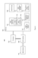
- Fig. 1 is a schematic representation of a system for mitigating microphone hiss.
- Fig. 2 is a further schematic representation of a system for mitigating microphone hiss.
- Fig. 3 is a flow diagram representing a method for mitigating microphone hiss.
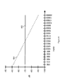
- Fig. 4 is a graphical representation of a microphone frequency spectrum including microphone hiss and a virtual noise floor.
- a system and method for mitigating microphone hiss may obtain a frequency spectrum characteristic for a sound input transducer such as, for example, a microphone.
- a microphone that has limited dynamic range with may create microphone hiss in an output signal generated by the microphone.
- the microphone hiss may prevent a reproduction of a sound field, represented in an output signal of the microphone, from being perceived as a natural environment.
- the microphone frequency spectrum characteristics (a.k.a. microphone frequency spectrum) may be obtained using static measurements or calculated dynamically.
- a virtual noise floor may be calculated responsive to the microphone frequency spectrum and a desired noise floor.
- Gain coefficients may be calculated responsive to the output signal of the microphone (a.k.a. the microphone signal).
- the gain coefficients may be calculated to mitigate undesirable signal content including background noise and echoes.
- the calculated gain coefficients may be modified responsive to the virtual noise floor.
- the modified gain coefficients may allow a reproduction of the sound field to be perceived as a natural environment.
- FIG. 1 is a schematic representation of a system for mitigating microphone hiss.
- One or more microphones 102 may receive a sound field.
- the sound field is a representation of an audible environment associated with the microphone 102.
- Many audible environments associated with the microphone 102 may include undesirable content that may be mitigated by processing a microphone signal 120 derived from the received sound field.
- Microphones 102 that are arranged in a far field configuration typically receive more undesirable content (a.k.a. noise) than microphones 102 in a near field configuration.
- Far field configurations may include, for example, a hands free phone, a conference phone and microphones embedded into an automobile.
- Far field configurations are capable of receiving a sound field that represents the spatial environment associated with the microphones 102.
- Near field configurations typically place the microphone 102 in close proximity to a sound source (e.g. a user).
- Undesirable content may be mitigated in both near and far field configurations by processing the microphone signal 120 derived from
- the microphone 102 may be chosen for an application based on cost, size or dynamic range over a specified frequency range (a.k.a. frequency response). For example, a microphone 102 utilized in a professional recording application may have a large dynamic range close to the range of human perception from 0 Hz to 16 kHz. The microphone 102 utilized in a mobile phone may have an acceptable dynamic range for speech content from 0 Hz to 5 kHz. The microphones 102 utilized in the mobile phone may be selected for cost reasons but often the dynamic range over a give frequency range may be limited because of the physical size of the microphone. Mobile phones, and many other computing devices, utilize small microphones because of the small physical size of the computing devices.
- Physically small microphones may have limitations of the dynamic range over a given frequency range.
- a common limitation may be limited dynamic range.
- the limited dynamic range may be audible even in the presence of a completely silent environment.
- the limited dynamic range may be heard as microphone hiss in the output signal of the microphone.
- Figure 4 is a graphical representation of a microphone frequency spectrum including microphone hiss and a virtual noise floor.
- the example microphone frequency spectrum 402 shows a frequency spectrum that may be acceptable for some applications below approximately 5 kHz where the level of microphone hiss is acceptable but frequencies greater than 5 kHz the level microphone hiss is unacceptable.
- Some narrow band applications including those primarily directed toward speech communication may find the microphone frequency spectrum 402 to be acceptable.
- Wide band applications attempting to receive, for example, a sound field to capture speech, music and the associated audible environment may find the microphone frequency spectrum 402 unacceptable due to the microphone hiss.
- Narrow band applications may digitally sample the microphone 102 at 8 kHz whereas wide band applications may sample the microphone 102 at higher sampling rates. Common higher sampling rates may include 16 kHz, 24 kHz, 44.1 kHz and 48 kHz. In a natural, quiet environment, a user may perceive the combined noise of the environment and the microphone hiss.
- Processing that may mitigate undesirable content received in the sound field may include a gain coefficient calculator 104.
- the gain coefficient calculator 104 may comprise one or more of a noise suppressor 106 and an echo canceller 108.
- the echo canceller 108, noise suppressor 106 and other audio processing processes may calculate one or more gain coefficients, or suppression gains.
- the echo canceller 108 and the noise suppressor 106 may each calculate one or more gain coefficients. Each respective gain coefficient may be applied individually or a composite gain coefficient may be applied to process the sound field using a gain coefficient applier 110.
- the echo canceller 108 mitigates echoes caused by signal feedback between two or more communication devices.
- Signal feedback occurs when an audio transducer on a first communication device reproduces the signal received from a second communication device and subsequently the microphones on the first communication device recapture the reproduced signal.
- the recaptured signal may be transmitted to the second communication device where the recaptured signal may be perceived as an echo of the previously transmitted signal.
- the echo canceller 108 may detect when a portion of the received signal has been recaptured and attempt to suppress the recaptured portion of the signal.
- Many different types of echo cancellers 108 may mitigate echoes by calculating one or more gain coefficients that, when applied to the signals received by the microphone 102, suppress the echoes.
- the echo canceller 108 may calculate gain coefficients using a coherence calculation between near and far signals disclosed in U.S. Patent No. 8,036,879 , which is incorporated herein by reference, except that in the event of any inconsistent disclosure or definition from the present specification, the disclosure or definition herein shall be deemed to prevail.
- the echo canceller 108 may use other mechanisms.
- Background noise is another type of undesirable signal content that may be mitigated by processing the microphone signal 120.
- Many different types of noise suppressor 106 techniques may mitigate background noise.
- An exemplary noise suppressor 106 is a recursive Wiener filter.
- the Wiener suppression gain G i , k S ⁇ N ⁇ ⁇ R priori i , k S ⁇ N ⁇ ⁇ R priori i , k + 1 .
- N ⁇ i,k is a background noise estimate.
- the background noise estimate, or signal values may be calculated using the background noise estimation techniques disclosed in U.S. Patent No. 7,844,453 , which is incorporated herein by reference, except that in the event of any inconsistent disclosure or definition from the present specification, the disclosure or definition herein shall be deemed to prevail.
- alternative background noise estimation techniques may be used, such as, for example, a noise power estimation technique based on minimum statistics.
- the noise suppressor 106 may use other mechanisms.
- Noise suppression techniques including the exemplary Wiener filter described above may mitigate some microphone hiss.
- Mitigating microphone hiss using standard noise suppression may reduce the audible hiss created by the microphone 102 although the resulting output 112 may not be perceived as a natural environment.
- Natural environments for example a room response, may have a noise floor that changes at a rate of 1/frequency, or -6 dB per octave.
- a noise floor that changes at a rate of approximately -5 dB to -7 dB per octave may be perceived as a natural environment.
- the noise suppressor 106 may reduce the amount of hiss created by the microphone 102 but the result may not be perceived as a natural environment.
- the noise suppressor 106 may generate gain coefficients that result in an output 112 that is perceived as a natural environment when the generated gain coefficients are modified to simulate a natural environment. For example, gain coefficients that result in an output 112 where the hiss noise changes at a rate of approximately -6 dB per octave may be perceived as a natural environment.
- a microphone spectrum obtainer 114 may obtain the microphone frequency spectrum 402.
- the microphone spectrum obtainer 114 may obtain the microphone frequency spectrum 402 utilizing an offline measurement tool.
- the microphone spectrum obtainer 114 may obtain the microphone frequency spectrum 402 dynamically by analyzing the microphone signal 120 over time and frequency. Obtaining a dynamic frequency spectrum 402 may include utilizing the background noise estimate.
- a virtual noise floor calculator 116 may calculate a virtual noise floor 404 that simulates (e.g. approximates) a natural environment.
- the microphone hiss may distort the audible environment received by the microphone 102 when reproduced in an output 112.
- the output 112 when reproduced with the virtual noise floor 404 may be perceived as a more natural environment.
- the virtual noise floor 404 may be calculated responsive to the microphone frequency spectrum 402.
- the virtual noise floor calculator 116 may calculate the virtual noise floor 404 starting from a frequency beyond which microphone hiss may become audible when compared to a natural environment.
- the virtual noise floor calculator 116 may update the virtual noise floor 404 as the microphone frequency spectrum 402 changes responsive to the microphone spectrum obtainer 114.
- the virtual noise floor 404 may be responsive to detected signal content. For example if no signal content is detected above 10 kHz, comfort noise may be added to the level of the virtual noise floor 404.
- a gain coefficient modifier 118 may modify the gain coefficients calculated by the gain coefficient calculator 104.
- the gain coefficient modifier 118 may modify the gain coefficients responsive to the virtual noise floor 404 calculated by the virtual noise floor calculator 116.
- the gain coefficient modifier 118 may modify the gain coefficients by increasing or decreasing the value of the gain coefficients.
- the gain coefficients from the example Wiener filter described above may be modified by limiting the gain coefficients to track the virtual noise floor 404.
- Equation 4 limits the gain coefficients calculated by the Wiener filter from suppressing noise below the virtual noise floor 404.
- An alternative gain coefficient modifier 118 may filter, or smooth, the gain coefficients over time and/or frequency. The gain coefficients may be modified resulting in the output 112 being below the virtual noise floor 404 responsive to a different limiting method and/or filtering. Gain coefficients that result in the output 112 being substantially lower than the virtual noise floor 404 may be perceived as a different type of natural environment including for example a large room as compared to a small room.
- the gain coefficient modifier 118 allows more noise removal with increasing frequency. For example, 20 dB (decibel) of noise removal between 8 to 10 kHz and 30 dB of noise removal between 15 to 20 kHz.
- Gain coefficients calculated with the echo canceller 108 may be modified by the gain coefficient modifier 118 in accordance with equation 4.
- additional noise may be added to the signal after the echo canceller 108 to obtain an output 112 that is approximately the same energy level as the virtual noise floor 404.
- the additional noise may be comfort noise with substantially the same energy level as the virtual noise floor.
- the comfort noise may me added for any gain coefficient calculator 104.
- a subband filter may process the signal from the microphone 102 to extract frequency information.
- the subband filtering may be accomplished by various methods, such as a Fast Fourier Transform (FFT), critical filter bank, octave filter band, or one-third octave filter bank.
- the subband analysis may include a time-based filter bank.
- the time-based filter bank may be composed of a bank of overlapping bandpass filters, where the center frequencies have non-linear spacing such as octave, 3 rd octave, bark, mel, or other spacing techniques.
- the one or more gain coefficients may be calculated for each frequency bin or band of the subband filter.
- Figure 3 is a flow diagram representing a method for mitigating microphone hiss.
- the method 300 may be, for example, implemented using the systems 100 and 200 described herein with reference to Figures 1 and 2 .
- the method 300 includes the act of obtaining a microphone frequency spectrum.
- a virtual noise floor may be calculated responsive to the microphone frequency spectrum and a desired noise floor 304.
- Gain coefficients may be calculated responsive to the microphone signal 306. The calculated gain coefficients may be modified responsive to the virtual noise floor 308.
- FIG. 2 is a further schematic representation of a system for mitigating microphone hiss.
- the system 200 comprises a processor 202, memory 204 (the contents of which are accessible by the processor 202), microphones 102 and an I/O interface 206.
- the memory 204 may store instructions which when executed using the process 202 may cause the system 200 to render the functionality associated with mitigating microphone hiss as described herein.
- the memory 204 may store instructions which when executed using the process 202 may cause the system 200 to render the functionality associated with the gain coefficient calculator module 104, the noise suppressor module 106, the echo canceller module 108, the gain coefficient applier module 110, the microphone spectrum obtainer module 114, the virtual noise floor calculator 116 and the gain coefficient modifier module 118 described herein.
- data structures, temporary variables and other information may store data in data storage 208.
- the processor 202 may comprise a single processor or multiple processors that may be disposed on a single chip, on multiple devices or distributed over more that one system.
- the processor 202 may be hardware that executes computer executable instructions or computer code embodied in the memory 204 or in other memory to perform one or more features of the system.
- the processor 202 may include a general purpose processor, a central processing unit (CPU), a graphics processing unit (GPU), an application specific integrated circuit (ASIC), a digital signal processor (DSP), a field programmable gate array (FPGA), a digital circuit, an analog circuit, a microcontroller, any other type of processor, or any combination thereof.
- the memory 204 may comprise a device for storing and retrieving data, processor executable instructions, or any combination thereof.
- the memory 204 may include non-volatile and/or volatile memory, such as a random access memory (RAM), a read-only memory (ROM), an erasable programmable read-only memory (EPROM), or a flash memory.
- RAM random access memory
- ROM read-only memory
- EPROM erasable programmable read-only memory
- flash memory a flash memory.
- the memory 204 may comprise a single device or multiple devices that may be disposed on one or more dedicated memory devices or on a processor or other similar device.
- the memory 204 may include an optical, magnetic (hard-drive) or any other form of data storage device.
- the memory 204 may store computer code, such as the gain coefficient calculator module 104, the noise suppressor module 106, the echo canceller module 108, the gain coefficient applier module 110, the microphone spectrum obtainer module 114, the virtual noise floor calculator 116 and the gain coefficient modifier module 118 as described herein.
- the computer code may include instructions executable with the processor 202.
- the computer code may be written in any computer language, such as C, C++, assembly language, channel program code, and/or any combination of computer languages.
- the memory 204 may store information in data structures including, for example, gain coefficients and state variables.
- the I/O interface 206 may be used to connect devices such as, for example, the microphone 102, and to other components of the system 200.
- the system 100 and 200 may include more, fewer, or different components than illustrated in Figure 2 . Furthermore, each one of the components of system 100 and 200 may include more, fewer, or different elements than is illustrated in Figure 1 and 2 .
- Flags, data, databases, tables, entities, and other data structures may be separately stored and managed, may be incorporated into a single memory or database, may be distributed, or may be logically and physically organized in many different ways.
- the components may operate independently or be part of a same program or hardware.
- the components may be resident on separate hardware, such as separate removable circuit boards, or share common hardware, such as a same memory and processor for implementing instructions from the memory. Programs may be parts of a single program, separate programs, or distributed across several memories and processors.
- the functions, acts or tasks illustrated in the figures or described may be executed in spectrum to one or more sets of logic or instructions stored in or on computer readable media.
- the functions, acts or tasks are independent of the particular type of instructions set, storage media, processor or processing strategy and may be performed by software, hardware, integrated circuits, firmware, micro code and the like, operating alone or in combination.
- processing strategies may include multiprocessing, multitasking, parallel processing, distributed processing, and/or any other type of processing.
- the instructions are stored on a removable media device for reading by local or remote systems.
- the logic or instructions are stored in a remote location for transfer through a computer network or over telephone lines.
- the logic or instructions may be stored within a given computer such as, for example, a CPU.
Landscapes
- Engineering & Computer Science (AREA)
- Physics & Mathematics (AREA)
- Acoustics & Sound (AREA)
- Signal Processing (AREA)
- Computational Linguistics (AREA)
- Quality & Reliability (AREA)
- Health & Medical Sciences (AREA)
- Audiology, Speech & Language Pathology (AREA)
- Human Computer Interaction (AREA)
- Multimedia (AREA)
- Circuit For Audible Band Transducer (AREA)
Priority Applications (1)
| Application Number | Priority Date | Filing Date | Title |
|---|---|---|---|
| EP13153113.9A EP2760221A1 (de) | 2013-01-29 | 2013-01-29 | Mikrofonzischabschwächung |
Applications Claiming Priority (1)
| Application Number | Priority Date | Filing Date | Title |
|---|---|---|---|
| EP13153113.9A EP2760221A1 (de) | 2013-01-29 | 2013-01-29 | Mikrofonzischabschwächung |
Publications (1)
| Publication Number | Publication Date |
|---|---|
| EP2760221A1 true EP2760221A1 (de) | 2014-07-30 |
Family
ID=47713888
Family Applications (1)
| Application Number | Title | Priority Date | Filing Date |
|---|---|---|---|
| EP13153113.9A Ceased EP2760221A1 (de) | 2013-01-29 | 2013-01-29 | Mikrofonzischabschwächung |
Country Status (1)
| Country | Link |
|---|---|
| EP (1) | EP2760221A1 (de) |
Cited By (1)
| Publication number | Priority date | Publication date | Assignee | Title |
|---|---|---|---|---|
| US10504501B2 (en) | 2016-02-02 | 2019-12-10 | Dolby Laboratories Licensing Corporation | Adaptive suppression for removing nuisance audio |
Citations (7)
| Publication number | Priority date | Publication date | Assignee | Title |
|---|---|---|---|---|
| US5937377A (en) * | 1997-02-19 | 1999-08-10 | Sony Corporation | Method and apparatus for utilizing noise reducer to implement voice gain control and equalization |
| US20050278171A1 (en) * | 2004-06-15 | 2005-12-15 | Acoustic Technologies, Inc. | Comfort noise generator using modified doblinger noise estimate |
| EP1739657A2 (de) * | 2005-06-28 | 2007-01-03 | Harman Becker Automotive Systems-Wavemakers, Inc. | System für adaptive Verstärkung von Sprachsignalen |
| US20070156399A1 (en) * | 2005-12-29 | 2007-07-05 | Fujitsu Limited | Noise reducer, noise reducing method, and recording medium |
| US7844453B2 (en) | 2006-05-12 | 2010-11-30 | Qnx Software Systems Co. | Robust noise estimation |
| US8036879B2 (en) | 2007-05-07 | 2011-10-11 | Qnx Software Systems Co. | Fast acoustic cancellation |
| WO2011159858A1 (en) * | 2010-06-17 | 2011-12-22 | Dolby Laboratories Licensing Corporation | Method and apparatus for reducing the effect of environmental noise on listeners |
-
2013
- 2013-01-29 EP EP13153113.9A patent/EP2760221A1/de not_active Ceased
Patent Citations (7)
| Publication number | Priority date | Publication date | Assignee | Title |
|---|---|---|---|---|
| US5937377A (en) * | 1997-02-19 | 1999-08-10 | Sony Corporation | Method and apparatus for utilizing noise reducer to implement voice gain control and equalization |
| US20050278171A1 (en) * | 2004-06-15 | 2005-12-15 | Acoustic Technologies, Inc. | Comfort noise generator using modified doblinger noise estimate |
| EP1739657A2 (de) * | 2005-06-28 | 2007-01-03 | Harman Becker Automotive Systems-Wavemakers, Inc. | System für adaptive Verstärkung von Sprachsignalen |
| US20070156399A1 (en) * | 2005-12-29 | 2007-07-05 | Fujitsu Limited | Noise reducer, noise reducing method, and recording medium |
| US7844453B2 (en) | 2006-05-12 | 2010-11-30 | Qnx Software Systems Co. | Robust noise estimation |
| US8036879B2 (en) | 2007-05-07 | 2011-10-11 | Qnx Software Systems Co. | Fast acoustic cancellation |
| WO2011159858A1 (en) * | 2010-06-17 | 2011-12-22 | Dolby Laboratories Licensing Corporation | Method and apparatus for reducing the effect of environmental noise on listeners |
Non-Patent Citations (1)
| Title |
|---|
| DREISEITEL PIA ET AL: "Speech enhancement for mobile telephony based on non-uniformly spaced frequency resolution", 9TH EUROPEAN SIGNAL PROCESSING CONFERENCE (EUSIPCO 1998), IEEE, 8 September 1998 (1998-09-08), pages 1 - 4, XP032766924, ISBN: 978-960-7620-06-4, [retrieved on 20150420] * |
Cited By (1)
| Publication number | Priority date | Publication date | Assignee | Title |
|---|---|---|---|---|
| US10504501B2 (en) | 2016-02-02 | 2019-12-10 | Dolby Laboratories Licensing Corporation | Adaptive suppression for removing nuisance audio |
Similar Documents
| Publication | Publication Date | Title |
|---|---|---|
| RU2569006C2 (ru) | Эхоподавление, содержащее моделирование компонентов поздней реверберации | |
| US9060052B2 (en) | Single channel, binaural and multi-channel dereverberation | |
| EP2629294B1 (de) | System und Verfahren für dynamische Restgeräuschformung | |
| US9106196B2 (en) | Sound field spatial stabilizer with echo spectral coherence compensation | |
| US9854358B2 (en) | System and method for mitigating audio feedback | |
| EP2860989A2 (de) | System und Verfahren zum dynamischen Mischen von Audiosignalen | |
| US20140321655A1 (en) | Sensitivity Calibration Method and Audio Device | |
| US20190267022A1 (en) | Apparatus and method for processing an audio signal | |
| US9756440B2 (en) | Maintaining spatial stability utilizing common gain coefficient | |
| US9949034B2 (en) | Sound field spatial stabilizer | |
| US9099973B2 (en) | Sound field spatial stabilizer with structured noise compensation | |
| US9349383B2 (en) | Audio bandwidth dependent noise suppression | |
| US9210507B2 (en) | Microphone hiss mitigation | |
| US9743179B2 (en) | Sound field spatial stabilizer with structured noise compensation | |
| EP2760221A1 (de) | Mikrofonzischabschwächung | |
| KR20200095370A (ko) | 음성 신호에서의 마찰음의 검출 | |
| EP2816818B1 (de) | Räumlicher Schallfeldstabilisator mit Echo-Spektralkohärenzkompensation | |
| EP2816817B1 (de) | Räumlicher Schallfeldstabilisator mit Spektralkohärenzkompensation | |
| CA2840730C (en) | Maintaining spatial stability utilizing common gain coefficient | |
| EP2760021B1 (de) | Räumlicher Schallfeldstabilisator | |
| EP2816816B1 (de) | Räumlicher Schallfeldstabilisator mit strukturierter Rauschkompensation | |
| CA2835991C (en) | Sound field spatial stabilizer | |
| EP2760020B1 (de) | Aufrechterhaltung der räumlichen Stabilität unter Verwendung eines gemeinsamen Gain-Koeffizienten | |
| EP2760022B1 (de) | Audiobandbreitenabhängige Geräuschunterdrückung |
Legal Events
| Date | Code | Title | Description |
|---|---|---|---|
| PUAI | Public reference made under article 153(3) epc to a published international application that has entered the european phase |
Free format text: ORIGINAL CODE: 0009012 |
|
| 17P | Request for examination filed |
Effective date: 20130129 |
|
| AK | Designated contracting states |
Kind code of ref document: A1 Designated state(s): AL AT BE BG CH CY CZ DE DK EE ES FI FR GB GR HR HU IE IS IT LI LT LU LV MC MK MT NL NO PL PT RO RS SE SI SK SM TR |
|
| AX | Request for extension of the european patent |
Extension state: BA ME |
|
| RAP1 | Party data changed (applicant data changed or rights of an application transferred) |
Owner name: 2236008 ONTARIO INC. |
|
| 17Q | First examination report despatched |
Effective date: 20150819 |
|
| STAA | Information on the status of an ep patent application or granted ep patent |
Free format text: STATUS: THE APPLICATION HAS BEEN REFUSED |
|
| 18R | Application refused |
Effective date: 20161122 |