EP2760385B1 - Einrichtung zur stützung und stabilisierung eines verletzten - Google Patents
Einrichtung zur stützung und stabilisierung eines verletzten Download PDFInfo
- Publication number
- EP2760385B1 EP2760385B1 EP12775428.1A EP12775428A EP2760385B1 EP 2760385 B1 EP2760385 B1 EP 2760385B1 EP 12775428 A EP12775428 A EP 12775428A EP 2760385 B1 EP2760385 B1 EP 2760385B1
- Authority
- EP
- European Patent Office
- Prior art keywords
- filling
- films
- granular material
- passages
- interior
- Prior art date
- Legal status (The legal status is an assumption and is not a legal conclusion. Google has not performed a legal analysis and makes no representation as to the accuracy of the status listed.)
- Not-in-force
Links
- 230000000087 stabilizing effect Effects 0.000 title description 3
- 239000008187 granular material Substances 0.000 claims description 23
- 229920006248 expandable polystyrene Polymers 0.000 claims description 6
- 238000004519 manufacturing process Methods 0.000 claims description 3
- 238000000034 method Methods 0.000 claims 1
- 230000003019 stabilising effect Effects 0.000 claims 1
- 150000001875 compounds Chemical class 0.000 description 3
- 239000011888 foil Substances 0.000 description 3
- 239000002245 particle Substances 0.000 description 3
- 238000012856 packing Methods 0.000 description 2
- 238000005192 partition Methods 0.000 description 2
- 239000004033 plastic Substances 0.000 description 2
- 229920003023 plastic Polymers 0.000 description 2
- 239000002985 plastic film Substances 0.000 description 2
- 229920006255 plastic film Polymers 0.000 description 2
- 230000006641 stabilisation Effects 0.000 description 2
- 238000011105 stabilization Methods 0.000 description 2
- QNRATNLHPGXHMA-XZHTYLCXSA-N (r)-(6-ethoxyquinolin-4-yl)-[(2s,4s,5r)-5-ethyl-1-azabicyclo[2.2.2]octan-2-yl]methanol;hydrochloride Chemical compound Cl.C([C@H]([C@H](C1)CC)C2)CN1[C@@H]2[C@H](O)C1=CC=NC2=CC=C(OCC)C=C21 QNRATNLHPGXHMA-XZHTYLCXSA-N 0.000 description 1
- 229920000426 Microplastic Polymers 0.000 description 1
- 239000011324 bead Substances 0.000 description 1
- 238000006073 displacement reaction Methods 0.000 description 1
- 239000000463 material Substances 0.000 description 1
- 229920002635 polyurethane Polymers 0.000 description 1
- 239000004814 polyurethane Substances 0.000 description 1
- 238000002360 preparation method Methods 0.000 description 1
- 230000000276 sedentary effect Effects 0.000 description 1
Images

Classifications
-
- A—HUMAN NECESSITIES
- A61—MEDICAL OR VETERINARY SCIENCE; HYGIENE
- A61F—FILTERS IMPLANTABLE INTO BLOOD VESSELS; PROSTHESES; DEVICES PROVIDING PATENCY TO, OR PREVENTING COLLAPSING OF, TUBULAR STRUCTURES OF THE BODY, e.g. STENTS; ORTHOPAEDIC, NURSING OR CONTRACEPTIVE DEVICES; FOMENTATION; TREATMENT OR PROTECTION OF EYES OR EARS; BANDAGES, DRESSINGS OR ABSORBENT PADS; FIRST-AID KITS
- A61F5/00—Orthopaedic methods or devices for non-surgical treatment of bones or joints; Nursing devices ; Anti-rape devices
- A61F5/01—Orthopaedic devices, e.g. long-term immobilising or pressure directing devices for treating broken or deformed bones such as splints, casts or braces
- A61F5/04—Devices for stretching or reducing fractured limbs; Devices for distractions; Splints
- A61F5/05—Devices for stretching or reducing fractured limbs; Devices for distractions; Splints for immobilising
- A61F5/058—Splints
- A61F5/05833—Splints rigidified by vacuum evacuation
Definitions
- the invention relates to a device for supporting and stabilizing an injured person, having a flexible film element which can be fixed on the injured part or an injured body part and which has two films and an evacuable interior containing granules, the two films being arranged along the edge and at points in FIG Domes are substantially point-shaped interconnected so that channels remain parallel to at least one side edge.
- Such also referred to as vacuum mattresses and vacuum rails stabilizing devices for transport and immobilization of the injured have a shell of an airtight plastic film and a filling of a plastic granules, in particular of foamed polystyrene beads, and can after adjustment and fixation on a sedentary body part by means of a suction pump be evacuated.
- fastening straps are arranged in the circumferential direction of the body part and provided with conventional adjustable connection fittings.
- Vacuum mattresses and rails are mainly suitable for horizontal use.
- a device of the type mentioned above is also known, which is also suitable for an upright transport of an injured person, wherein an upper body support cushion and a headrest cushion can be fastened to a stiffening frame.
- the cushions each consist of two airtight films that run along their edges and are interconnected in three places inside. The internal connections hinder the free movement of the granules, so that it remains substantially in place despite the upright use.
- the invention has now set itself the task of finding a practicable compromise, which represents a simple, material-saving production, a satisfactory, full-surface stiffness of the evacuated support element and a rapid and the requirements corresponding adaptability to the circumstances.
- such a compromise is achieved in that the inner connections are arranged in a four-point grid.
- the filling lances or tubes protrude in a row next to each other from a reservoir filled with granules down, preferably to be filled foil elements are pushed from below onto the filling lances and lowered again as the filling progresses.
- the compounds arranged in the four-point grid also have the disadvantages mentioned at the outset, namely that no granules can be present at each connection point and that the connection points in each row or column represent a line-shaped weak point along which the stiffness after evacuation is lower than in FIG remaining areas.
- the connection points in each row or column represent a line-shaped weak point along which the stiffness after evacuation is lower than in FIG remaining areas.
- sufficient strength of the evacuated sheet member is maintained.
- the channels lying between the joints have, for example, a width of about 10 cm and a thickness of about 3 cm, and the filling consists mainly of a granules of foamed polystyrene with a weight between 20 kg / m 3 and 70 kg / m 3 , in particular of 60 kg / m 3 , wherein the average diameter of the individual particles between 0.4 mm and 5 mm, in particular between 0.5 mm and 2 mm.
- a preferred embodiment of the connection provides that the four-point grid is oblique to the channels, wherein the four points are in each case in particular at the corners of a square. The distance of the connecting points in the longitudinal and transverse direction is thereby increased to the length of the diagonal, and the stability is good in both directions.
- a film element 1 which is suitable depending on the size and shape for immobilization and stabilization of an injured body part, such as a broken arm or leg, or an injured person has two films 2 of an airtight plastic, for example, a polyurethane, along along the edge circumferentially and connected to each other at points 3 inside, in particular welded.
- the interior 4 contains a granulate 7 made of a lightweight plastic, in particular of a foamed polystyrene, wherein the diameter of the individual balls is in particular between 0.5 and 2 mm.
- connection points 3 are arranged in the interior so that the granules also when lifting the film element 1 or when used in a vertical position, such as the upper body stabilization of a seated injured, not down can slip, but remains approximately evenly distributed.
- the arrangement of the connection points 3 follows a four-point grid, as from the in Fig.
- dashed lines drawn grid lines 5 can be seen, wherein the grid lines 5 are shown extending obliquely to the side walls of the film element 1.
- the grid lines 5 can also be parallel to the side edges as well.
- the distance between each two connection points 3 is preferably the same size, that is, the grid is square, possibly rhombic, and is about 10 cm.
- the dimensions and arrangement may vary somewhat, but in any case they are such that continuous, parallel channels 6 remain in the longitudinal direction of the film element.
- Such a film element can be produced as follows:
Landscapes
- Health & Medical Sciences (AREA)
- Animal Behavior & Ethology (AREA)
- Veterinary Medicine (AREA)
- Engineering & Computer Science (AREA)
- Biomedical Technology (AREA)
- Heart & Thoracic Surgery (AREA)
- Vascular Medicine (AREA)
- Orthopedic Medicine & Surgery (AREA)
- General Health & Medical Sciences (AREA)
- Life Sciences & Earth Sciences (AREA)
- Public Health (AREA)
- Nursing (AREA)
- Basic Packing Technique (AREA)
- Mattresses And Other Support Structures For Chairs And Beds (AREA)
- Invalid Beds And Related Equipment (AREA)
- Laminated Bodies (AREA)
Description
- Die Erfindung betrifft eine Einrichtung zur Stützung und Stabilisierung eines Verletzten, mit einem flexiblen, am Verletzten bzw. an einem verletzten Körperteil festlegbaren Folienelement, das zwei Folien und einen Granulat enthaltenden, evakuierbaren Innenraum aufweist, wobei die beiden Folien entlang des Randes und an Stellen im Inneren im Wesentlichen punktförmig so miteinander verbunden sind, dass Kanäle parallel zu mindestens einem Seitenrand verbleiben.
- Derartige auch als Vakuummatratzen und Vakuumschienen bezeichnete Stabilisierungseinrichtungen für Transport und Immobilisierung des Verletzten weisen eine Hülle aus einer luftdichten Kunststofffolie und eine Füllung aus einem Kunststoffgranulat, insbesondere aus geschäumten Polystyrolkugeln, auf und können nach der Anpassung und Fixierung an einem ruhig zu stellenden Körperteil mittels einer Saugpumpe evakuiert werden. Dies führt zu einer dichten Packung des lose eingefüllten Granulats und somit zu einer Versteifung des flexiblen Elements, das auf diese Weise eine im Wesentlichen starre Hülle oder Manschette bildet. Für eine möglichst universelle Fixierung am Körperteil sind Befestigungsgurte in Umfangsrichtung des Körperteils angeordnet und mit üblichen einstellbaren Verbindungsbeschlägen versehen. Vakuummatratzen und -schienen sind hauptsächlich für eine horizontale Einsatzlage geeignet. Bei Verwendung in einer nicht horizontalen Lage, beispielsweise bei sitzenden Verletzten, besteht die Gefahr, daß die Füllung in einem höheren Bereich eine dünnere Schicht bildet oder sogar fehlt, weil sie sich während der Handhabung von oben nach unten verlagert hat. Es wurde daher vorgeschlagen (
US 5,154,185 A ) den Innenraum durch horizontale Trennwände in schmälere Kammern zu unterteilen, wobei die Trennwände Durchbrechungen aufweisen, die gerade so groß sind, daß Teile der Füllung nur händisch hindurchgedrückt werden können. - Aus der
WO 99/16392 A - Abgesehen von durch die inneren Verbindungen verursachten Erschwernisse bei der Herstellung der Stützeinrichtungen ergeben sich zwangsläufig überall dort Bereiche ohne Granulat, wo die beiden Folien direkt miteinander verbunden sind und somit auch Bereiche, in denen trotz des Vakuums die Aussteifung der Stützeinrichtung mangelhaft ist und eine ungünstige Beweglichkeit erhalten bleibt.
- In der
WO 01/30280 - Die Erfindung hat es sich nun zur Aufgabe gestellt, einen praktikablen Kompromiss zu finden, der eine einfache, Material sparende Herstellung, eine zufriedenstellende, vollflächige Steifigkeit des evakuierten Stützelementes und eine rasche und den Erfordernissen entsprechende Anpassbarkeit an die Gegebenheiten darstellt.
- Erfindungsgemäß wird ein derartiger Kompromiss dadurch erreicht, dass die inneren Verbindungen in einem Vierpunktraster angeordnet sind.
- Es hat sich gezeigt, dass Verbindungen, die in einem Vierpunktraster über das gesamte Folienelement verteilt werden, aufgrund der Reibung zwischen den Partikeln des Granulats völlig ausreichend sind, um eine annähernd gleichmäßige Schichtdicke auch bei lotrechter Anordnung zu bewahren, wobei aber eine händische Verlagerung von Partikeln zur Anpassung an den Einsatzort sich verhältnismäßig leicht bewerkstelligen lässt. Die Herstellung der punktförmigen Verbindungen kann bei den üblicherweise verwendeten schweißbaren Kunststofffolien von außen erfolgen, und die Befüllung mit Granulat lässt sich erfindungsgemäß in einfacher Weise dadurch erzielen, dass in jeden Kanal eine Fülllanze eingeschoben und durch die Fülllanzen Granulat zugeführt wird, wobei die Fülllanzen entsprechend dem Füllfortschritt wieder herausgezogen werden, und dass schließlich die Folien am offenen oberen Querrand verbunden werden.
- Da die Fülllanzen bzw. -rohre in einer Reihe nebeneinander von einem mit Granulat gefüllten Vorratsbehälter nach unten abstehen, werden bevorzugt die zu füllenden Folienelemente von unten auf die Fülllanzen aufgeschoben und mit fortschreitender Füllung wieder abgesenkt.
- Die im Vierpunktraster angeordneten Verbindungen weisen natürlich auch die eingangs erwähnten Nachteile auf, nämlich, dass an jeder Verbindungsstelle kein Granulat liegen kann und dass die Verbindungsstellen in jeder Reihe oder Spalte eine linienförmige Schwachstelle darstellen, entlang der die Steifheit nach dem Evakuieren geringer ist als in den übrigen Bereichen. Aufgrund der örtlichen Beschränktheit der punktförmigen Verbindungen und des durch die einander kreuzenden Kanäle relativ großen Abstands zwischen den Verbindungsstellen bleibt aber für die meisten Anwendungsfälle eine ausreichende Festigkeit des evakuierten Folienelementes erhalten. Die zwischen den Verbindungsstellen liegenden Kanäle weisen beispielsweise eine Breite von ca. 10 cm und eine Dicke von ca. 3 cm auf, und die Füllung besteht vor allem aus einem Granulat aus geschäumtem Polystyrol mit einem Gewicht zwischen 20 kg/m3 und 70 kg/m3, insbesondere von 60 kg/m3, wobei der mittlere Durchmesser der einzelnen Partikel zwischen 0,4 mm und 5 mm, insbesondere zwischen 0,5 mm und 2 mm ist. Eine bevorzugte Ausführung der Verbindung sieht dabei vor, dass das Vierpunktraster schräg zu den Kanälen ist, wobei die vier Punkte insbesondere jeweils an den Ecken eines Quadrats liegen. Der Abstand der Verbindungspunkte in Längs- und Querrichtung erhöht sich dadurch auf die Länge der Diagonalen, und die Stabilität ist in beiden Richtungen gut.
- Nachstehend wird nun die Erfindung an Hand der Figuren der beiliegenden Zeichnung näher beschrieben, ohne darauf beschränkt zu sein. Es zeigen:
- Fig. 1
- eine schematische Ansicht eines rechteckigen Folienelementes,
- Fig. 2
- einen Schnitt nach der Linie II-II der
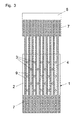
Fig. 1 und - Fig. 3
- eine schematische Darstellung der Füllung des Folienelementes von
Fig. 1 mit Granulat. - Ein Folienelement 1, das je nach Größe und Formgebung zur Immobilisierung und Stabilisierung eines verletzten Körperteils, beispielsweise eines gebrochenen Armes oder Beines, oder einer verletzten Person geeignet ist, weist zwei Folien 2 aus einem luftdichten Kunststoff, beispielsweise aus einem Polyurethan, auf, die entlang des Randes umlaufend und an Stellen 3 im Inneren miteinander verbunden, insbesondere verschweißt sind. Der Innenraum 4 enthält ein Granulat 7 aus einem leichten Kunststoff, insbesondere aus einem geschäumten Polystyrol, wobei der Durchmesser der einzelnen Kugeln insbesondere zwischen 0,5 und 2 mm liegt. Eine der beiden Folien 2 ist mit einem nicht gezeigten Ventil versehen, über das die im Innenraum 4 eingeschlossene Luft abgesaugt werden kann, wodurch das lose eingefüllte und im Innenraum 4 durch äußere Einwirkung verschiebbare bzw. verlagerbare Granulat 7 in eine dichte Packung überführt wird, die das Folienelement 1 ausreichend versteift, um eine Bewegung des verletzten Körpers bzw. Körperteils zu unterbinden. Da das Folienelement 1 nicht nur in horizontaler Lage eingesetzt werden kann, sind die Verbindungsstellen 3 im Inneren so angeordnet, dass das Granulat auch beim Anheben des Folienelementes 1 bzw. bei Verwendung in vertikaler Lage, etwa bei der Oberkörperstabilisierung eines sitzenden Verletzten, nicht nach unten rutschen kann, sondern annähernd gleichmäßig verteilt bleibt. Die Anordnung der Verbindungsstellen 3 folgt dabei einem Vierpunktraster, wie aus den in
Fig. 1 strichliert eingezeichneten Rasterlinien 5 ersichtlich ist, wobei die Rasterlinien 5 schräg zu den Seitenwänden des Folienelementes 1 verlaufend dargestellt sind. Die Rasterlinien 5 können aber ebenso auch parallel zu den Seitenrändern sein. Der Abstand zwischen je zwei Verbindungsstellen 3 ist bevorzugt gleich groß, das heißt, das Raster ist quadratisch, gegebenenfalls rhombisch, und beträgt ca. 10 cm. Die Maße und Anordnung können etwas variieren, jedoch sind sie in jedem Fall so, dass in Längsrichtung des Folienelementes durchgehende, parallele Kanäle 6 verbleiben. Ein derartiges Folienelement kann wie folgt hergestellt werden: - Zwei in der passenden Größe zugeschnittene Folien 2 werden an drei Seitenrändern und an den durch das Vierpunktraster vorgegebenen Verbindungsstellen 3 im Inneren miteinander verschweißt, sodass ein oben offenes sackähnliches Gebilde entsteht. Wie aus
Fig. 3 ersichtlich, werden in die Kanäle 2 des oben offenen Folienelementes 1 zueinander parallele Fülllanzen 9 bzw. Füllrohre eingeführt, die von der Unterseite eines Granulat 7 beinhaltenden Behälters 8 ausgehen. Werden die nicht gezeigten Bodenauslässe des Behälters 8 geöffnet, rieselt das Granulat 7 durch jede Füllzone 9 nach unten in das Folienelement 1, das langsam nach unten abgesenkt wird, und sich dadurch mit dem Granulat 7 füllt. Anschließend werden die Folien 2 auch entlang des oberen Randes verbunden. Wie ausFig. 3 ersichtlich, können die Fülllanzen 9 über die gesamte Höhe des Folienelementes 1 die Verbindungsstellen 3 passieren, und die Füllung verteilt sich beim Absenken des Folienelementes in die zwischen den Kanälen 6 liegenden Freiräume, die direkt zwischen zwei übereinander liegenden Verbindungsstellen 3 liegen.
Claims (9)
- Einrichtung zur Stützung und Stabilisierung eines Verletzten, mit einem flexiblen, am Verletzten festlegbaren Folienelement (1), das zwei Folien (2) und einen Granulat (9) enthaltenden, evakuierbaren Innenraum (4) aufweist, wobei die beiden Folien (2) entlang des Randes und an Stellen (3) im Inneren im Wesentlichen punktförmig so miteinander verbunden sind, dass Kanäle (6) parallel zu mindestens einem Seitenrand verbleiben, dadurch gekennzeichnet, dass die inneren Verbindungen (3) in einem Vierpunktraster (5) angeordnet sind.
- Einrichtung nach Anspruch 1, dadurch gekennzeichnet, dass das Vierpunktraster (5) schräg zu den Kanälen (6) ist.
- Einrichtung nach Anspruch 2, dadurch gekennzeichnet, dass das Vierpunktraster (5) gleiche Seitenlängen aufweist.
- Einrichtung nach einem der Ansprüche 1 bis 3, dadurch gekennzeichnet, dass die Anordnung der inneren Verbindungen mehrere Zeilen und Spalten mit jeweils mehr als zwei Verbindungsstellen (3) umfasst.
- Einrichtung nach einem der Ansprüche 1 bis 4, dadurch gekennzeichnet, dass das Granulat (9) aus geschäumtem Polystyrol mit einem Gewicht zwischen 20 kg/m3 und 70 kg/m3 besteht.
- Einrichtung nach einem der Ansprüche 1 bis 4, dadurch gekennzeichnet, dass das Granulat (9) aus geschäumtem Polystyrol mit einem Durchmesser zwischen 0,4 mm und 5 mm besteht.
- Einrichtung nach einem der Ansprüche 1 bis 6, dadurch gekennzeichnet, dass das Granulat (9) aus geschäumtem Polystyrol mit einem Gewicht von 60 kg/m3 und einem Durchmesser zwischen 0,5 mm und 2 mm besteht.
- Einrichtung nach einem der Ansprüche 1 bis 7, dadurch gekennzeichnet, dass die Kanäle eine Breite von ca. 10 cm und eine Dicke von ca. 3 cm aufweisen.
- Verfahren zur Herstellung einer Einrichtung nach einem der Ansprüche 1 bis 8, dadurch gekennzeichnet, dass zwei Folien (2) unten, seitlich und punktuell im Inneren so miteinander verbunden werden, dass zueinander parallele, nach oben offene Kanäle (6) verbleiben, dass in jeden Kanal (6) eine Fülllanze (9) eingeschoben und durch die Fülllanzen (9) Granulat (7) zugeführt wird, wobei die Fülllanzen (9) entsprechend dem Füllfortschritt wieder herausgezogen werden, und dass schließlich die Folien (2) am offenen oberen Querrand verbunden werden.
Applications Claiming Priority (2)
| Application Number | Priority Date | Filing Date | Title |
|---|---|---|---|
| AT13952011A AT510555B1 (de) | 2011-09-27 | 2011-09-27 | Einrichtung zur stützung und stabilisierung eines verletzten sowie verfahren zur herstellung der einrichtung |
| PCT/AT2012/000239 WO2013044277A1 (de) | 2011-09-27 | 2012-09-17 | Einrichtung zur stützung und stabilisierung eines verletzten |
Publications (2)
| Publication Number | Publication Date |
|---|---|
| EP2760385A1 EP2760385A1 (de) | 2014-08-06 |
| EP2760385B1 true EP2760385B1 (de) | 2015-09-16 |
Family
ID=46052377
Family Applications (1)
| Application Number | Title | Priority Date | Filing Date |
|---|---|---|---|
| EP12775428.1A Not-in-force EP2760385B1 (de) | 2011-09-27 | 2012-09-17 | Einrichtung zur stützung und stabilisierung eines verletzten |
Country Status (3)
| Country | Link |
|---|---|
| EP (1) | EP2760385B1 (de) |
| AT (1) | AT510555B1 (de) |
| WO (1) | WO2013044277A1 (de) |
Families Citing this family (2)
| Publication number | Priority date | Publication date | Assignee | Title |
|---|---|---|---|---|
| AT523472A1 (de) * | 2020-01-28 | 2021-08-15 | Kohlbrat & Bunz Gmbh | Verfahren zur Herstellung einer Einrichtung zur Stützung und Stabilisierung eines Verletzten |
| AT18570U1 (de) * | 2020-01-28 | 2025-11-15 | Kohlbrat & Bunz Gmbh | Verfahren zum Befüllen eines flexiblen Elementes zur Stützung und Stabilisierung eines Verletzten |
Family Cites Families (4)
| Publication number | Priority date | Publication date | Assignee | Title |
|---|---|---|---|---|
| US5154185A (en) | 1990-11-14 | 1992-10-13 | Hartwell Medical Corporation | Air evacuable support |
| JP2001508693A (ja) | 1997-09-28 | 2001-07-03 | ヴォルフガング シュテルツェンミューラー | 個々の肢或いは身体各部分を固定するための救急用支持器具 |
| WO2001030280A1 (de) | 1999-10-25 | 2001-05-03 | Kohlbrat & Bunz Gesellschaft M.B.H. | Einrichtung zur stützung und stabilisierung eines verletzten |
| AT501310B1 (de) * | 2002-07-09 | 2007-06-15 | Kohlbrat & Bunz Gmbh | Einrichtung zur stützung und stabilisierung eines verletzten menschen oder dessen verletzten körperteils sowie verfahren zu dessen herstellung |
-
2011
- 2011-09-27 AT AT13952011A patent/AT510555B1/de not_active IP Right Cessation
-
2012
- 2012-09-17 EP EP12775428.1A patent/EP2760385B1/de not_active Not-in-force
- 2012-09-17 WO PCT/AT2012/000239 patent/WO2013044277A1/de not_active Ceased
Also Published As
| Publication number | Publication date |
|---|---|
| AT510555B1 (de) | 2012-05-15 |
| AT510555A4 (de) | 2012-05-15 |
| WO2013044277A1 (de) | 2013-04-04 |
| EP2760385A1 (de) | 2014-08-06 |
Similar Documents
| Publication | Publication Date | Title |
|---|---|---|
| EP1223899B1 (de) | Einrichtung zur stützung und stabilisierung eines verletzten | |
| DE60125309T2 (de) | Luftmatratze | |
| DE3108607C2 (de) | ||
| EP2463449B1 (de) | Strukturkörper für ein Rigolensystem und Rigolensystem | |
| EP0040807A1 (de) | Bauelementsystem zur Erstellung bepflanzbarer Stützmauern | |
| DE102012023148A1 (de) | Vakuummatratze gemäß DE 10 2011 114 082.8 | |
| EP2760385B1 (de) | Einrichtung zur stützung und stabilisierung eines verletzten | |
| DE102015012579A1 (de) | Matratze vom Fluid-Zell-Typ | |
| AT501310B1 (de) | Einrichtung zur stützung und stabilisierung eines verletzten menschen oder dessen verletzten körperteils sowie verfahren zu dessen herstellung | |
| EP4096593B1 (de) | Verfahren zum befüllen eines flexiblen elementes zur stützung und stabilisierung eines verletzten | |
| WO2011009960A1 (de) | Gewächshaus | |
| AT523470A2 (de) | Verfahren zum Befüllen eines flexiblen Elementes zur Stützung und Stabilisierung eines Verletzten | |
| DE60000202T2 (de) | Matratze mit Luftkissen | |
| DE202017104249U1 (de) | Decke, insbesondere Bettdecke | |
| AT525236B1 (de) | Einrichtung zur Stützung und Stabilisierung von Lebewesen | |
| EP1319377B1 (de) | Vorrichtung zur Stützung und Stabilisierung eines Verletzten | |
| DE1504116B1 (de) | Mehrschichtige Verbundkonstruktion | |
| DE202013006180U1 (de) | Aufblasbare Matte | |
| DE3104720A1 (de) | Wassermatratze bzw. wasserbett | |
| DE8810361U1 (de) | Polster zur Hochlagerung der Beine | |
| EP2468143B1 (de) | Geschäumter Matratzenkörper | |
| DE7016676U (de) | Vorgefertigtes bauelement fuer die herstellung von silos oder anderen lagerbehaeltern. | |
| DE8012389U1 (de) | Stallbodenbelagsbahn | |
| DE2020975A1 (de) | Halle mit flexibler Huelle | |
| DE2615216B1 (de) | Stapelbarer,tablettartiger Traeger fuer Sektflaschendrahtbuegel |
Legal Events
| Date | Code | Title | Description |
|---|---|---|---|
| PUAI | Public reference made under article 153(3) epc to a published international application that has entered the european phase |
Free format text: ORIGINAL CODE: 0009012 |
|
| 17P | Request for examination filed |
Effective date: 20140217 |
|
| AK | Designated contracting states |
Kind code of ref document: A1 Designated state(s): AL AT BE BG CH CY CZ DE DK EE ES FI FR GB GR HR HU IE IS IT LI LT LU LV MC MK MT NL NO PL PT RO RS SE SI SK SM TR |
|
| DAX | Request for extension of the european patent (deleted) | ||
| RIN1 | Information on inventor provided before grant (corrected) |
Inventor name: RUGFELT, HAKAN |
|
| GRAP | Despatch of communication of intention to grant a patent |
Free format text: ORIGINAL CODE: EPIDOSNIGR1 |
|
| INTG | Intention to grant announced |
Effective date: 20150318 |
|
| GRAS | Grant fee paid |
Free format text: ORIGINAL CODE: EPIDOSNIGR3 |
|
| GRAA | (expected) grant |
Free format text: ORIGINAL CODE: 0009210 |
|
| AK | Designated contracting states |
Kind code of ref document: B1 Designated state(s): AL AT BE BG CH CY CZ DE DK EE ES FI FR GB GR HR HU IE IS IT LI LT LU LV MC MK MT NL NO PL PT RO RS SE SI SK SM TR |
|
| REG | Reference to a national code |
Ref country code: GB Ref legal event code: FG4D Free format text: NOT ENGLISH |
|
| REG | Reference to a national code |
Ref country code: CH Ref legal event code: EP |
|
| REG | Reference to a national code |
Ref country code: IE Ref legal event code: FG4D Free format text: LANGUAGE OF EP DOCUMENT: GERMAN |
|
| REG | Reference to a national code |
Ref country code: AT Ref legal event code: REF Ref document number: 749193 Country of ref document: AT Kind code of ref document: T Effective date: 20151015 |
|
| REG | Reference to a national code |
Ref country code: DE Ref legal event code: R096 Ref document number: 502012004608 Country of ref document: DE |
|
| REG | Reference to a national code |
Ref country code: FR Ref legal event code: PLFP Year of fee payment: 4 |
|
| REG | Reference to a national code |
Ref country code: NL Ref legal event code: MP Effective date: 20150916 |
|
| PG25 | Lapsed in a contracting state [announced via postgrant information from national office to epo] |
Ref country code: GR Free format text: LAPSE BECAUSE OF FAILURE TO SUBMIT A TRANSLATION OF THE DESCRIPTION OR TO PAY THE FEE WITHIN THE PRESCRIBED TIME-LIMIT Effective date: 20151217 Ref country code: NO Free format text: LAPSE BECAUSE OF FAILURE TO SUBMIT A TRANSLATION OF THE DESCRIPTION OR TO PAY THE FEE WITHIN THE PRESCRIBED TIME-LIMIT Effective date: 20151216 Ref country code: LV Free format text: LAPSE BECAUSE OF FAILURE TO SUBMIT A TRANSLATION OF THE DESCRIPTION OR TO PAY THE FEE WITHIN THE PRESCRIBED TIME-LIMIT Effective date: 20150916 Ref country code: LT Free format text: LAPSE BECAUSE OF FAILURE TO SUBMIT A TRANSLATION OF THE DESCRIPTION OR TO PAY THE FEE WITHIN THE PRESCRIBED TIME-LIMIT Effective date: 20150916 Ref country code: FI Free format text: LAPSE BECAUSE OF FAILURE TO SUBMIT A TRANSLATION OF THE DESCRIPTION OR TO PAY THE FEE WITHIN THE PRESCRIBED TIME-LIMIT Effective date: 20150916 |
|
| REG | Reference to a national code |
Ref country code: LT Ref legal event code: MG4D |
|
| PG25 | Lapsed in a contracting state [announced via postgrant information from national office to epo] |
Ref country code: SE Free format text: LAPSE BECAUSE OF FAILURE TO SUBMIT A TRANSLATION OF THE DESCRIPTION OR TO PAY THE FEE WITHIN THE PRESCRIBED TIME-LIMIT Effective date: 20150916 Ref country code: HR Free format text: LAPSE BECAUSE OF FAILURE TO SUBMIT A TRANSLATION OF THE DESCRIPTION OR TO PAY THE FEE WITHIN THE PRESCRIBED TIME-LIMIT Effective date: 20150916 Ref country code: RS Free format text: LAPSE BECAUSE OF FAILURE TO SUBMIT A TRANSLATION OF THE DESCRIPTION OR TO PAY THE FEE WITHIN THE PRESCRIBED TIME-LIMIT Effective date: 20150916 |
|
| PG25 | Lapsed in a contracting state [announced via postgrant information from national office to epo] |
Ref country code: NL Free format text: LAPSE BECAUSE OF FAILURE TO SUBMIT A TRANSLATION OF THE DESCRIPTION OR TO PAY THE FEE WITHIN THE PRESCRIBED TIME-LIMIT Effective date: 20150916 |
|
| PG25 | Lapsed in a contracting state [announced via postgrant information from national office to epo] |
Ref country code: EE Free format text: LAPSE BECAUSE OF FAILURE TO SUBMIT A TRANSLATION OF THE DESCRIPTION OR TO PAY THE FEE WITHIN THE PRESCRIBED TIME-LIMIT Effective date: 20150916 Ref country code: ES Free format text: LAPSE BECAUSE OF FAILURE TO SUBMIT A TRANSLATION OF THE DESCRIPTION OR TO PAY THE FEE WITHIN THE PRESCRIBED TIME-LIMIT Effective date: 20150916 Ref country code: SK Free format text: LAPSE BECAUSE OF FAILURE TO SUBMIT A TRANSLATION OF THE DESCRIPTION OR TO PAY THE FEE WITHIN THE PRESCRIBED TIME-LIMIT Effective date: 20150916 Ref country code: CZ Free format text: LAPSE BECAUSE OF FAILURE TO SUBMIT A TRANSLATION OF THE DESCRIPTION OR TO PAY THE FEE WITHIN THE PRESCRIBED TIME-LIMIT Effective date: 20150916 Ref country code: IS Free format text: LAPSE BECAUSE OF FAILURE TO SUBMIT A TRANSLATION OF THE DESCRIPTION OR TO PAY THE FEE WITHIN THE PRESCRIBED TIME-LIMIT Effective date: 20160116 |
|
| REG | Reference to a national code |
Ref country code: CH Ref legal event code: PL |
|
| PG25 | Lapsed in a contracting state [announced via postgrant information from national office to epo] |
Ref country code: PL Free format text: LAPSE BECAUSE OF FAILURE TO SUBMIT A TRANSLATION OF THE DESCRIPTION OR TO PAY THE FEE WITHIN THE PRESCRIBED TIME-LIMIT Effective date: 20150916 Ref country code: RO Free format text: LAPSE BECAUSE OF FAILURE TO SUBMIT A TRANSLATION OF THE DESCRIPTION OR TO PAY THE FEE WITHIN THE PRESCRIBED TIME-LIMIT Effective date: 20150916 Ref country code: PT Free format text: LAPSE BECAUSE OF FAILURE TO SUBMIT A TRANSLATION OF THE DESCRIPTION OR TO PAY THE FEE WITHIN THE PRESCRIBED TIME-LIMIT Effective date: 20160118 |
|
| REG | Reference to a national code |
Ref country code: DE Ref legal event code: R097 Ref document number: 502012004608 Country of ref document: DE |
|
| REG | Reference to a national code |
Ref country code: IE Ref legal event code: MM4A |
|
| PG25 | Lapsed in a contracting state [announced via postgrant information from national office to epo] |
Ref country code: MC Free format text: LAPSE BECAUSE OF FAILURE TO SUBMIT A TRANSLATION OF THE DESCRIPTION OR TO PAY THE FEE WITHIN THE PRESCRIBED TIME-LIMIT Effective date: 20150916 |
|
| PLBE | No opposition filed within time limit |
Free format text: ORIGINAL CODE: 0009261 |
|
| STAA | Information on the status of an ep patent application or granted ep patent |
Free format text: STATUS: NO OPPOSITION FILED WITHIN TIME LIMIT |
|
| PG25 | Lapsed in a contracting state [announced via postgrant information from national office to epo] |
Ref country code: IE Free format text: LAPSE BECAUSE OF NON-PAYMENT OF DUE FEES Effective date: 20150917 Ref country code: CH Free format text: LAPSE BECAUSE OF NON-PAYMENT OF DUE FEES Effective date: 20150930 Ref country code: LI Free format text: LAPSE BECAUSE OF NON-PAYMENT OF DUE FEES Effective date: 20150930 |
|
| 26N | No opposition filed |
Effective date: 20160617 |
|
| PG25 | Lapsed in a contracting state [announced via postgrant information from national office to epo] |
Ref country code: DK Free format text: LAPSE BECAUSE OF FAILURE TO SUBMIT A TRANSLATION OF THE DESCRIPTION OR TO PAY THE FEE WITHIN THE PRESCRIBED TIME-LIMIT Effective date: 20150916 |
|
| REG | Reference to a national code |
Ref country code: FR Ref legal event code: PLFP Year of fee payment: 5 |
|
| PG25 | Lapsed in a contracting state [announced via postgrant information from national office to epo] |
Ref country code: SI Free format text: LAPSE BECAUSE OF FAILURE TO SUBMIT A TRANSLATION OF THE DESCRIPTION OR TO PAY THE FEE WITHIN THE PRESCRIBED TIME-LIMIT Effective date: 20150916 |
|
| PG25 | Lapsed in a contracting state [announced via postgrant information from national office to epo] |
Ref country code: MT Free format text: LAPSE BECAUSE OF FAILURE TO SUBMIT A TRANSLATION OF THE DESCRIPTION OR TO PAY THE FEE WITHIN THE PRESCRIBED TIME-LIMIT Effective date: 20150916 |
|
| PG25 | Lapsed in a contracting state [announced via postgrant information from national office to epo] |
Ref country code: BG Free format text: LAPSE BECAUSE OF FAILURE TO SUBMIT A TRANSLATION OF THE DESCRIPTION OR TO PAY THE FEE WITHIN THE PRESCRIBED TIME-LIMIT Effective date: 20150916 Ref country code: HU Free format text: LAPSE BECAUSE OF FAILURE TO SUBMIT A TRANSLATION OF THE DESCRIPTION OR TO PAY THE FEE WITHIN THE PRESCRIBED TIME-LIMIT; INVALID AB INITIO Effective date: 20120917 Ref country code: SM Free format text: LAPSE BECAUSE OF FAILURE TO SUBMIT A TRANSLATION OF THE DESCRIPTION OR TO PAY THE FEE WITHIN THE PRESCRIBED TIME-LIMIT Effective date: 20150916 |
|
| PG25 | Lapsed in a contracting state [announced via postgrant information from national office to epo] |
Ref country code: CY Free format text: LAPSE BECAUSE OF FAILURE TO SUBMIT A TRANSLATION OF THE DESCRIPTION OR TO PAY THE FEE WITHIN THE PRESCRIBED TIME-LIMIT Effective date: 20150916 |
|
| PG25 | Lapsed in a contracting state [announced via postgrant information from national office to epo] |
Ref country code: BE Free format text: LAPSE BECAUSE OF NON-PAYMENT OF DUE FEES Effective date: 20150930 |
|
| REG | Reference to a national code |
Ref country code: FR Ref legal event code: PLFP Year of fee payment: 6 |
|
| PG25 | Lapsed in a contracting state [announced via postgrant information from national office to epo] |
Ref country code: LU Free format text: LAPSE BECAUSE OF NON-PAYMENT OF DUE FEES Effective date: 20150917 |
|
| PG25 | Lapsed in a contracting state [announced via postgrant information from national office to epo] |
Ref country code: MK Free format text: LAPSE BECAUSE OF FAILURE TO SUBMIT A TRANSLATION OF THE DESCRIPTION OR TO PAY THE FEE WITHIN THE PRESCRIBED TIME-LIMIT Effective date: 20150916 Ref country code: TR Free format text: LAPSE BECAUSE OF FAILURE TO SUBMIT A TRANSLATION OF THE DESCRIPTION OR TO PAY THE FEE WITHIN THE PRESCRIBED TIME-LIMIT Effective date: 20150916 |
|
| REG | Reference to a national code |
Ref country code: FR Ref legal event code: PLFP Year of fee payment: 7 |
|
| PG25 | Lapsed in a contracting state [announced via postgrant information from national office to epo] |
Ref country code: AL Free format text: LAPSE BECAUSE OF FAILURE TO SUBMIT A TRANSLATION OF THE DESCRIPTION OR TO PAY THE FEE WITHIN THE PRESCRIBED TIME-LIMIT Effective date: 20150916 |
|
| REG | Reference to a national code |
Ref country code: AT Ref legal event code: MM01 Ref document number: 749193 Country of ref document: AT Kind code of ref document: T Effective date: 20170917 |
|
| PG25 | Lapsed in a contracting state [announced via postgrant information from national office to epo] |
Ref country code: AT Free format text: LAPSE BECAUSE OF NON-PAYMENT OF DUE FEES Effective date: 20170917 |
|
| PGFP | Annual fee paid to national office [announced via postgrant information from national office to epo] |
Ref country code: IT Payment date: 20190925 Year of fee payment: 8 Ref country code: FR Payment date: 20190930 Year of fee payment: 8 |
|
| PGFP | Annual fee paid to national office [announced via postgrant information from national office to epo] |
Ref country code: GB Payment date: 20190916 Year of fee payment: 8 |
|
| PGFP | Annual fee paid to national office [announced via postgrant information from national office to epo] |
Ref country code: DE Payment date: 20190927 Year of fee payment: 8 |
|
| REG | Reference to a national code |
Ref country code: DE Ref legal event code: R119 Ref document number: 502012004608 Country of ref document: DE |
|
| GBPC | Gb: european patent ceased through non-payment of renewal fee |
Effective date: 20200917 |
|
| PG25 | Lapsed in a contracting state [announced via postgrant information from national office to epo] |
Ref country code: DE Free format text: LAPSE BECAUSE OF NON-PAYMENT OF DUE FEES Effective date: 20210401 Ref country code: FR Free format text: LAPSE BECAUSE OF NON-PAYMENT OF DUE FEES Effective date: 20200930 |
|
| PG25 | Lapsed in a contracting state [announced via postgrant information from national office to epo] |
Ref country code: GB Free format text: LAPSE BECAUSE OF NON-PAYMENT OF DUE FEES Effective date: 20200917 |
|
| PG25 | Lapsed in a contracting state [announced via postgrant information from national office to epo] |
Ref country code: IT Free format text: LAPSE BECAUSE OF NON-PAYMENT OF DUE FEES Effective date: 20200917 |