EP2760432B1 - Procédé pour fonctionnaliser une couverture de membrane d'un capteur optique pour faciliter le couplage d'un agent antithrombogène - Google Patents
Procédé pour fonctionnaliser une couverture de membrane d'un capteur optique pour faciliter le couplage d'un agent antithrombogène Download PDFInfo
- Publication number
- EP2760432B1 EP2760432B1 EP12835936.1A EP12835936A EP2760432B1 EP 2760432 B1 EP2760432 B1 EP 2760432B1 EP 12835936 A EP12835936 A EP 12835936A EP 2760432 B1 EP2760432 B1 EP 2760432B1
- Authority
- EP
- European Patent Office
- Prior art keywords
- heparin
- membrane
- sensor
- coating
- disclosures
- Prior art date
- Legal status (The legal status is an assumption and is not a legal conclusion. Google has not performed a legal analysis and makes no representation as to the accuracy of the status listed.)
- Active
Links
- 0 **(*)(*)Cc1ccccc1 Chemical compound **(*)(*)Cc1ccccc1 0.000 description 1
Images




Classifications
-
- G—PHYSICS
- G01—MEASURING; TESTING
- G01N—INVESTIGATING OR ANALYSING MATERIALS BY DETERMINING THEIR CHEMICAL OR PHYSICAL PROPERTIES
- G01N33/00—Investigating or analysing materials by specific methods not covered by groups G01N1/00 - G01N31/00
- G01N33/48—Biological material, e.g. blood, urine; Haemocytometers
- G01N33/50—Chemical analysis of biological material, e.g. blood, urine; Testing involving biospecific ligand binding methods; Immunological testing
- G01N33/66—Chemical analysis of biological material, e.g. blood, urine; Testing involving biospecific ligand binding methods; Immunological testing involving blood sugars, e.g. galactose
-
- A—HUMAN NECESSITIES
- A61—MEDICAL OR VETERINARY SCIENCE; HYGIENE
- A61L—METHODS OR APPARATUS FOR STERILISING MATERIALS OR OBJECTS IN GENERAL; DISINFECTION, STERILISATION OR DEODORISATION OF AIR; CHEMICAL ASPECTS OF BANDAGES, DRESSINGS, ABSORBENT PADS OR SURGICAL ARTICLES; MATERIALS FOR BANDAGES, DRESSINGS, ABSORBENT PADS OR SURGICAL ARTICLES
- A61L33/00—Antithrombogenic treatment of surgical articles, e.g. sutures, catheters, prostheses, or of articles for the manipulation or conditioning of blood; Materials for such treatment
- A61L33/0005—Use of materials characterised by their function or physical properties
- A61L33/0011—Anticoagulant, e.g. heparin, platelet aggregation inhibitor, fibrinolytic agent, other than enzymes, attached to the substrate
- A61L33/0023—Anticoagulant, e.g. heparin, platelet aggregation inhibitor, fibrinolytic agent, other than enzymes, attached to the substrate using a quaternized group or a protonated amine group of the substrate
-
- G—PHYSICS
- G01—MEASURING; TESTING
- G01N—INVESTIGATING OR ANALYSING MATERIALS BY DETERMINING THEIR CHEMICAL OR PHYSICAL PROPERTIES
- G01N33/00—Investigating or analysing materials by specific methods not covered by groups G01N1/00 - G01N31/00
- G01N33/48—Biological material, e.g. blood, urine; Haemocytometers
- G01N33/50—Chemical analysis of biological material, e.g. blood, urine; Testing involving biospecific ligand binding methods; Immunological testing
- G01N33/53—Immunoassay; Biospecific binding assay; Materials therefor
- G01N33/543—Immunoassay; Biospecific binding assay; Materials therefor with an insoluble carrier for immobilising immunochemicals
- G01N33/54393—Improving reaction conditions or stability, e.g. by coating or irradiation of surface, by reduction of non-specific binding, by promotion of specific binding
-
- B—PERFORMING OPERATIONS; TRANSPORTING
- B05—SPRAYING OR ATOMISING IN GENERAL; APPLYING FLUENT MATERIALS TO SURFACES, IN GENERAL
- B05D—PROCESSES FOR APPLYING FLUENT MATERIALS TO SURFACES, IN GENERAL
- B05D3/00—Pretreatment of surfaces to which liquids or other fluent materials are to be applied; After-treatment of applied coatings, e.g. intermediate treating of an applied coating preparatory to subsequent applications of liquids or other fluent materials
- B05D3/14—Pretreatment of surfaces to which liquids or other fluent materials are to be applied; After-treatment of applied coatings, e.g. intermediate treating of an applied coating preparatory to subsequent applications of liquids or other fluent materials by electrical means
- B05D3/141—Plasma treatment
- B05D3/142—Pretreatment
-
- G—PHYSICS
- G01—MEASURING; TESTING
- G01N—INVESTIGATING OR ANALYSING MATERIALS BY DETERMINING THEIR CHEMICAL OR PHYSICAL PROPERTIES
- G01N2400/00—Assays, e.g. immunoassays or enzyme assays, involving carbohydrates
- G01N2400/10—Polysaccharides, i.e. having more than five saccharide radicals attached to each other by glycosidic linkages; Derivatives thereof, e.g. ethers, esters
- G01N2400/38—Heteroglycans, i.e. polysaccharides having more than one sugar residue in the main chain in either alternating or less regular sequence, e.g. gluco- or galactomannans, Konjac gum, Locust bean gum or Guar gum
- G01N2400/40—Glycosaminoglycans, i.e. GAG or mucopolysaccharides, e.g. chondroitin sulfate, dermatan sulfate, hyaluronic acid, heparin, heparan sulfate, and related sulfated polysaccharides
-
- G—PHYSICS
- G01—MEASURING; TESTING
- G01N—INVESTIGATING OR ANALYSING MATERIALS BY DETERMINING THEIR CHEMICAL OR PHYSICAL PROPERTIES
- G01N2650/00—Assays involving polymers whose constituent monomers bore biological functional groups before polymerization, i.e. vinyl, acryl derivatives of amino acids, sugars
-
- Y—GENERAL TAGGING OF NEW TECHNOLOGICAL DEVELOPMENTS; GENERAL TAGGING OF CROSS-SECTIONAL TECHNOLOGIES SPANNING OVER SEVERAL SECTIONS OF THE IPC; TECHNICAL SUBJECTS COVERED BY FORMER USPC CROSS-REFERENCE ART COLLECTIONS [XRACs] AND DIGESTS
- Y10—TECHNICAL SUBJECTS COVERED BY FORMER USPC
- Y10T—TECHNICAL SUBJECTS COVERED BY FORMER US CLASSIFICATION
- Y10T436/00—Chemistry: analytical and immunological testing
- Y10T436/14—Heterocyclic carbon compound [i.e., O, S, N, Se, Te, as only ring hetero atom]
- Y10T436/142222—Hetero-O [e.g., ascorbic acid, etc.]
- Y10T436/143333—Saccharide [e.g., DNA, etc.]
- Y10T436/144444—Glucose
Definitions
- Embodiments of the present invention generally relate to thromboresistant coatings for medical devices, such as intravascular glucose sensors, having a blood-contacting surface, as well as to methods for forming such coatings, and to the medical devices thus formed.
- Achieving glycemic control is facilitated by continuous or nearly continuous monitoring of patient blood glucose levels.
- One method for accomplishing such monitoring is through the use of an implanted glucose sensor.
- an optical glucose sensor such as those disclosed in U.S. Patent Nos. 5,137,033 , 5,512,246 , 5,503,770 , 6,627,177 , 7,417,164 and 7,470,420 , and U.S. Patent Publ. Nos. 2006/0083688 , 2008/0188722 , 2008/0188725 , 2008/0187655 , 2008/0305009 , 2009/0018426 , 2009/0018418 , and co-pending U.S. Patent Appl. Nos.
- 11/296,898 , 12/187,248 , 12/172,059 , 12/274,617 and 61/045,887 can be deployed in the vascular system of the patient, with glucose readings taken continuously, or as needed.
- any indwelling intravascular glucose sensor can potentially be used in monitoring glucose for the purpose of achieving glycemic control.
- thrombus can result in the restriction of blood flow through the blood vessel, impairing functionality of the sensor and/or health of the patient.
- the thrombus can break off and travel through the bloodstream to other parts of the body, such as the heart or brain, leading to severe health problems. As result, it is desirable to minimize the formation of a thrombus on or near the sensor.
- Heparin has been used clinically for decades as an intravenous anticoagulant to treat clotting disorders and to prevent thrombus formation during surgery and interventional procedures.
- Coating the outer surface of a medical device, e.g., stents, prostheses, catheters, tubing, and blood storage vessels, with heparin or a heparin containing complex See, e.g., U.S. Reissued Patent No. RE39,438 to Shah, et al.
- the heparin coating substantially shields the blood from the underlying surface of the medical device, such that the blood components contact the heparin coating rather than the device surface, thus reducing the formation of thrombi or emboli (blood clots that release and travel downstream).
- PSF polysulfone
- WO9115952A1 discloses thrombo-resistant coatings of cross-linked siloxane membranes for gas permeable surfaces, using amino functionalized siloxane membranes obtained by plasma treatment by radio frequency glow discharge plasma using ammonia, and coupling heparin to said amino-functionalized membranes.
- heparin may not provide a lasting and/or contiguous thromboresistant coating.
- Various strategies have been implemented to enhance the integrity of the heparin coating. For example, photo-activated coupling methods can be used to covalently bind heparin to a device surface thereby extending the useful life of the coating (See e.g., Surmodics' PHOTOLINK® process at www.surmodics.com/technologies-surface-biocompatibility-heparin.html).
- linkers such as tridodecylmethyl ammonium chloride (TDMAC) and PEO-polyethylene oxide, among others, have been used to space the heparin molecule away from the PVC surfaces (See e.g., US Pat. No. 5,441,759 to Crouther et al. ). Heparin may be cross-linked to polypeptides to create a thromboresistant hydrogel with peptide-specific functionality (See e.g., U.S. Patent No. 7,303,814 to Lamberti, et al. disclosing a wound-healing functionality).
- TDMAC tridodecylmethyl ammonium chloride
- PEO-polyethylene oxide among others
- Heparin derivatives or complexes such as heparin benzalkonium chloride (hereinafter "HBAC") have also been applied as a thromboresistant coating for medical devices.
- HBAC heparin benzalkonium chloride
- devices such as intravascular analyte sensors, that require passage of the analyte in the blood through the coating.
- Hsu US Patent No. 5,047,020 ) disclosed use of various heparin complexes for coating blood gas sensors and noted that the benzalkonium heparin complex was unsuitable for such an intravascular sensor.
- an analyte sensor comprising: an elongate member; an analyte-responsive indicator disposed along a distal portion of the elongate member, wherein the indicator is capable of generating a signal related to a concentration of analyte in the blood vessel; a semipermeable membrane covering at least the indicator along the distal portion of the elongate member; and a coating comprising heparin and benzalkonium stably associated with at least a portion of the semipermeable membrane.
- the elongate member comprises an optical fiber comprising a light path.
- the analyte-responsive indicator preferably comprises a fluorophore operably coupled to an analyte binding moiety, wherein analyte binding causes a change in the emission intensity of the fluorophore, and wherein the analyte responsive indictor is disposed within the light path of the optical fiber.
- the fluorophore is HPTS-triCysMA and the binding moiety is 3,3'-oBBV.
- the semipermeable membrane is a porous membrane.
- the porous membrane may comprise one or more polymers selected from a group consisting of the polyolefins, the fluoropolymers, the polycarbonates, and the polysulfones. More preferably, the porous membrane comprises at least one polysulfone. The at least one polysulfone may be selected from the group consisting of polyethersulfone.
- the porous membrane comprises at least one polyolefin.
- the polyolefin is preferably polyethylene.
- the semipermeable membrane does not include polysulfone (PSF).
- the semipermeable membrane comprises polyethersulfone/polyvinylpyrrolidone (PES/PVP).
- an analyte sensor comprising: an elongate member; an analyte-responsive indicator disposed along a distal portion of the elongate member, wherein said indicator is capable of generating a signal related to a concentration of analyte in a blood vessel; a semipermeable membrane covering at least the indicator along the distal portion of the elongate member; and a coating comprising heparin covalently bound to at least a portion of the semipermeable membrane, wherein said heparin is indirectly attached via a spacer to an amino-functionalized membrane and/or wherein said heparin is attached from a single site in said heparin to a single site on said amino-functionalized membrane or to said spacer.
- the spacer is polyethylene glycol.
- the semipermeable membrane is a porous membrane.
- the semipermeable membrane is associated with a hollow fiber that encloses an analyte responsive indicator.
- a cross-sectional geometry of at least a portion of the sensor is tapered so as to produce generally desirable blood flow characteristics when the sensor is placed in a blood vessel lumen.
- the equilibrium intravascular analyte sensor comprises: an optical fiber configured for positioning within a blood vessel and comprising a light path and an outer surface; a chemical indicator system comprising a fluorophore operably coupled to an analyte binding moiety, wherein the fluorophore and analyte binding moiety are immobilized within a water-insoluble organic polymer, and wherein the chemical indicator system is disposed within the light path along a distal portion of the optical fiber; and an antithrombogenic, analyte-permeable coating on at least a portion of the outer surface of the optical fiber and overlying the chemical indicator system disposed therein, wherein the coating comprises heparin covalently cross-linked to the outer surface.
- the fluorophore is preferably HPTS-triCysMA and the binding moiety is preferably 3,3'-oBBV.
- the equilibrium intravascular analyte sensor may further comprise a porous, analyte-permeable membrane disposed between the chemical indicator system and the antithrombogenic coating.
- a method for reducing the thrombogenicity of an analyte sensor comprises: providing the analyte sensor comprising an elongate optical fiber defining a light path, an equilibrium fluorescent chemical indicator system disposed along a distal region of the optical fiber within the light path, and an analyte-permeable porous membrane, which forms an outer layer of at least a portion of the distal region, wherein the indicator system is covered by the porous membrane; contacting the analyte sensor with a single solution comprising a mixture of heparin and benzalkonium, or with separate first and second solutions, wherein the first solution comprises heparin and the second solution comprises benzalkonium; drying the analyte sensor; and repeating the contacting and drying steps between 2 and 10 times.
- the equilibrium fluorescent chemical indicator system comprises a fluorophore and an analyte binding moiety, immobilized within a water-insoluble organic polymer.
- the fluorophore may be HPTS-triCysMA
- the binding moiety may be 3,3'-oBBV
- the water-insoluble organic polymer may be a DMAA ( N , N -dimethylacrylamide) hydrogel matrix.
- Another method for reducing the thrombogenicity of an analyte sensor.
- the method comprises: providing the analyte sensor comprising an elongate optical fiber defining a light path, an equilibrium fluorescent chemical indicator system disposed along a distal region of the optical fiber within the light path, and an analyte-permeable porous membrane, which forms an outer surface over at least a portion of the distal region, wherein the indicator system is covered by the porous membrane; providing a photoactivatable chemical linking agent and an antithrombogenic molecule, wherein the linking agent is capable, upon activation, of covalent attachment to the outer surface and the antithrombogenic molecule, wherein the linking agent comprises a charged, nonpolymeric di- or higher functional photoactivatable compound comprising two or more photoreactive groups and one or more charged groups; and activating the two or more photoreactive groups, thereby cross-linking the antithrombogenic molecule to the outer surface.
- the equilibrium fluorescent chemical indicator system preferably comprises a fluorophore and an analyte binding moiety, immobilized within a water-insoluble organic polymer.
- the fluorophore is HPTS-triCysMA
- the binding moiety is 3,3'-oBBV
- the water-insoluble organic polymer is a DMAA ( N , N -dimethylacrylamide) hydrogel matrix.
- the porous membrane comprises microporous polyethylene.
- Instant invention relates to a method of covalently attaching heparin to a membrane comprising: plasma treating the membrane to produce an amino-functionalized membrane; and reacting the amino-functionalized membrane with heparin under conditions in which heparin becomes covalently attached to the amino-functionalized membrane, wherein said heparin is indirectly attached via a spacer to said amino-functionalized membrane, wherein said heparin is attached from a single site in the heparin to a single site on the amino-functionalized membrane via the spacer, wherein said spacer is polyethylene glycol (PEG).
- PEG polyethylene glycol
- the plasma treatment is conducted with radio frequency glow discharge plasma.
- the plasma is selected from the group consisting of O 2 , allylamine and NH 3 , wherein said membrane is High Density Polyethylene (HDPE) membrane.
- HDPE High Density Polyethylene
- the method of covalently attaching heparin to a membrane additionally comprises the following step, wherein mpm means micro-porous membrane:
- the method of covalently attaching heparin to a membrane comprises the following steps:
- the EDC/NHS concentration is 10 mM.
- the membrane is PES membrane.
- the membrane is associated with a hollow fiber that encloses an analyte-responsive indicator.
- analyte sensors configured for in vivo deployment (e.g., intravascular, interstitial, etc.), preferably glucose sensors, wherein the sensors further comprise a thromboresistant outer surface, preferably a coating.
- Methods of coating sensors to create a thromoboresistant outer surface are also disclosed.
- intravascular sensors for detecting other analytes besides glucose may also benefit from aspects of the invention, e.g., reducing, inhibiting, and/or preventing blood clot or thrombus formation around the sensor.
- Porous is used herein to refer to material that has pores in it to allow permeation of chemical species through the material.
- the material can be “nanoporous” meaning the material has a mean pore diameter of less than about 2 nm.
- the material can be “microporous” meaning the material has a mean pore diameter between about 2 nm and about 50 nm.
- the material can be “mesoporous” meaning that the material has a mean pore diameter of greater than about 50 nm.
- the material can also be semipermeable, allowing only some chemical species to pass through while preventing or inhibiting other materials from passing through.
- Polyolefin is used herein to refer to polymers produced from olefins, including copolymers. Two primary examples are polyethylene and polypropylene. Many different grades of these are available, with the grades frequently described in terms of molecular weight or density. Polymers from longer chain monomers than two or three carbons are also included.
- Fluoropolymer is used herein to refer to polymers that contain chlorine and/or fluorine atoms. Examples include polytetrafluoroethylene, perfluoroalkoxy polymer, fluorinated ethylene-propylene, polyethylenetetrafluoroethylene, polyvinylfluoride, polyethylenechlorotrifluoroethylene, polyvinylidene fluoride, polychlorotrifluoroethylene, perfluoropolyether, perfluoroelastomer, and fluoroelastomer. These materials may be rigid or elastomeric.
- Trade names include TEFLON, TEFZEL, FLUON, TEDLAR, HALAR, KYNAR, KEL-F, CTFE, KALREZ, TECNOFLON, FFKM, VITON, FOMBLIN, and GALDEN.
- Polycarbonate is used herein to refer to polymers having functional groups linked by carbonate groups. Trade names include LEXAN, CALIBRE, MAKROLON, PANLITE, and MAKROLIFE.
- Polysulfone is used herein to refer to polymers containing the sulfone or sulfonyl group, and are most commonly made up of the subunit (aryl 1)-SO 2 -(aryl 2).
- Heparin as used herein includes polysaccharide materials having anticoagulant and/or antithrombotic properties, and is frequently referred to as containing alternating derivatives of D-glycocyamine (N-sulfated or N-acetylated) and uranic acid (L-iduronic acid with varying sulfate or D-glucuronic acid) joined by glycosidic linkages, or as including heterogeneous mixtures of variably sulfated polysaccharide chains composed of repeating units of D-glucosamine and either L-iduronic or D- glucuronic acids. Heparin can be derived from natural sources, such as bovine or porcine mucosal tissue, such as from the lung or intestine, and can have varying molecular weight.
- Benzalkonium chloride is used herein to refer to halogen salts of quaternary ammonium compounds and mixtures of quaternary ammonium compounds primarily having a benzyl and three R-groups attached to the nitrogen, as depicted in the following structure: where R1 is in alkyl group having from about one to about five carbons, R2 is an alkyl group having about one to about five carbons, R3 is an alkyl group having about six to about 22 carbons, and X - is a halogen counterion.
- chloride refers to a specific halogen counter ion having atomic number 17
- any halogen counter ion such as fluoride, chloride, bromide, iodide, etc.
- benzalkonium is used herein to refer to the quaternary ammonium compound itself.
- the halogen salt “benzalkonium chloride” comprises “benzalkonium” and a chloride counter ion.
- HBAC is used herein to refer to complexes of heparin and benzalkonium chloride. Varying grades and molecular weights of heparin can be used. Varying grades of benzalkonium chloride, as well as other salts of benzalkonium ion having various chain lengths for the R-groups, whether in purified or mixed forms, or combined with other related or unrelated compounds can also be used.
- GLUCATH® is the proprietary name for an optical glucose sensor configured for intravascular or subcutaneous deployment.
- the GLUCATH® sensor has an equilibrium fluorescent chemical indicator system preferably comprising a fluorophore and an analyte binding moiety, immobilized within a water-insoluble organic polymer.
- the fluorophore is HPTS-triCysMA
- the binding moiety is 3,3'-oBBV
- the water-insoluble organic polymer is a DMAA ( N , N -dimethylacrylamide) hydrogel matrix.
- the equilibrium optical glucose sensor may utilize fluorescent lifetime chemistry as described in US 2009/0018418A1 .
- Analyte sensors suitable for coating with a thromboresistant surface include those analyte sensors having a polymeric external surface on at least a portion of the sensor. Preferably, that portion of the sensor is configured for in vivo deployment, and more preferably for intravascular deployment.
- Polymeric materials known to be utilized as a portion of the external surface include hydrophobic polymers such as polyolefins (for example polyethylene and polypropylene), polycarbonate, and fluorocarbons.
- the polymeric material can be nanoporous. In some embodiments, the polymeric material can be microporous.
- the mean pore diameter may be between about 2nm and about 10nm, or between about 10nm and about 20nm, or between about 20nm and 30nm, or between about 30nm and about 40nm, or between about 40nm and about 50nm, including combinations of the aforementioned ranges.
- the mean pore diameter may be between about 10nm and about 30nm, or between about 20nm and about 40nm.
- the polymeric material can be mesoporous.
- the porous polymeric surface can be a covering or sheath for at least a portion of the body of the sensor.
- the polymeric surface can be made and/or applied by any suitable method.
- Sensors can be constructed in various ways, appropriate to the sensing chemistry/technique that is utilized by the sensor.
- an optical sensor such as a sensor producing a fluorescent response in relation to the analyte concentration can have a porous polymeric outer surface for at least a portion of the sensor assembly.
- a sensor can include an insoluble polymeric matrix, which immobilizes the analyte sensitive chemical indicator systems and is sufficiently permeable to the analyte of interest.
- Suitable polymeric matrix materials include those related to acrylic polymers.
- fluorophores and/or binders/quenchers can be incorporated into the polymeric matrix (See e.g., U.S. Patent Nos. 6,627,177 , 7,470,420 and 7,417,164 .
- an analyte sensor comprising: an elongate member; an analyte-responsive indicator disposed along a distal portion of the elongate member, wherein said indicator is capable of generating a signal related to a concentration of analyte in a blood vessel; a semipermeable membrane covering at least the indicator along the distal portion of the elongate member; and a coating comprising heparin covalently bound to at least a portion of the semipermeable membrane, wherein said heparin is indirectly attached via a spacer to an amino-functionalized membrane and/or wherein said heparin is attached from a single site in said heparin to a single site on said amino-functionalized membrane or to said spacer.
- any other intravascular glucose sensor may be used in accordance with the disclosure including for example the electrochemical sensors disclosed in U.S. Publication Nos. 2008/0119704 , 2008/0197024 , 2008/0200788 , 2008/0200789 and 2008/0200791 .
- the glucose sensor can be configured for implantation into a patient.
- implantation of the sensor may be made in the arterial or venous systems for direct testing of glucose levels in blood.
- the site of implantation may affect the particular shape, components, and configuration of the sensor.
- the sensor may be configured for interstitial deployment.
- glucose-sensing chemical indicator systems and glucose sensor configurations for intravascular glucose monitoring include the optical sensors disclosed in U.S. Patent Nos. 5,137,033 , 5,512,246 , 5,503,770 , 6,627,177 , 7,417,164 and 7,470,420 , and U.S. Patent Publ. Nos. 2008/0188722 , 2008/0188725 , 2008/0187655 , 2008/0305009 , 2009/0018426 , 2009/0018418 , and co-pending U.S. Patent Appl. Nos. 11/296,898 , 12/187,248 , 12/172,059 , 12/274,617 and 12/424,902 .
- glucose sensors configured for intravascular deployment include electrochemical sensors, such as those disclosed in U.S. Patent Publ. Nos. 2008/0119704 , 2008/0197024 , 2008/0200788 , 2008/0200789 and 2008/0200791 .
- An optical glucose sensor in accordance with preferred embodiments of the present disclosure comprises a chemical indicator system.
- Some useful indicator systems comprise a fluorophore operably coupled to an analyte binding moiety, wherein analyte binding causes an apparent optical change in the fluorophore concentration (e.g., emission intensity).
- a glucose binding moiety such as 3,3'-oBBV that is operably coupled to a fluorescent dye such as HPTS-triCysMA will quench the emission intensity of the fluorescent dye, wherein the extent of quenching is reduced upon glucose binding resulting in an increase in emission intensity related to glucose concentration.
- the indicator systems also comprise a means for immobilizing the sensing moieties (e.g., dye-quencher) such that they remain physically close enough to one another to react (quenching).
- immobilizing means are preferably insoluble in an aqueous environment (e.g., intravascular), permeable to the target analytes, and impermeable to the sensing moieties.
- the immobilizing means comprises a water-insoluble organic polymer matrix.
- the HPTS-triCysMA dye and 3,3'-oBBV quencher may be effectively immobilized within a DMAA ( N , N -dimethylacrylamide) hydrogel matrix.
- Some preferred fluorophores e.g., HPTS-triCysMA
- quenchers/analyte binding moieties e.g., 3,3'-oBBV
- immobilizing means e.g., N,N-dimethylacrylamide
- methods for synthesizing and assembling such indicator systems are set forth in greater detail in U.S. Patent Nos. 6,627,177 , 7,417,164 and 7,470,420 , and U.S. Patent Publ. Nos. 2008/0188722 , 2008/0188725 , 2008/0187655 , 2008/0305009 , 2009/0018426 , 2009/0018418 , and co-pending U.S. Patent Appl. Nos. 12/187,248 , 12/172,059 , 12/274,617 and 12/424,902 .
- An indicator system may comprise an analyte binding protein operably coupled to a fluorophore, such as the indicator systems and glucose binding proteins disclosed in U.S. Patent Nos. 6,197,534 , 6,227,627 , 6,521,447 , 6,855,556 , 7,064,103 , 7,316,909 , 7,326,538 , 7,345,160 , and 7,496,392 , U.S. Patent Application Publication Nos.
- FIG. 1 discloses a sensor 2 .
- the sensor comprises an optical fiber 10 with a distal end 12 disposed in a porous membrane sheath 14.
- the optical fiber 10 has cavities, such as holes 6A, in the fiber optic wall that can be formed by, for example, mechanical means such as drilling or cutting.
- the holes 6A in the optical fiber 10 can be filled with a suitable compound, such as a polymer.
- the polymer is a hydrogel 8.
- the optical fiber 10 does not have holes 6A, and instead, the hydrogel 8 is disposed in a space distal to the distal end 12 of the optical fiber 10 and proximal to the mirror 23.
- the sensor 2 is a glucose sensor.
- the glucose sensor is an intravascular glucose sensor.
- the porous membrane sheath 14 can be made from a polymeric material such as polyethylene, polycarbonate, polyethersulfone, a blend of polyethersulfone/polyvinylpyrrolidone, a high density polyethylene or polypropylene.
- the porous membrane sheath 14 is a hollow fiber membrane or associated with a hollow fiber membrane.
- the porous membrane sheath 14 is not made from polysulfone.
- Other materials can also be used to make the porous membrane sheath 14 such as zeolites, ceramics, metals, or combinations of these materials.
- the porous membrane sheath 14 may be nanoporous.
- the porous membrane sheath 14 may be microporous.
- the porous membrane sheath 14 may be mesoporous.
- the membrane according to the present invention is a high density polyethylene membrane.
- the porous membrane sheath 14 is attached to the optical fiber 10 by a connector 16.
- the connector 16 can be an elastic collar that holds the porous membrane sheath 14 in place by exerting a compressive force on the optical fiber 10, as shown in FIG. 2 .
- the connector 16 is an adhesive or a thermal weld.
- a mirror 23 and thermistor 25 can be placed within the porous membrane sheath 14 distal the distal end 12 of the optical fiber 10.
- Thermistor leads 27 can be made to run in a space between the optical fiber 10 and porous membrane sheath 14.
- a thermistor 25 is shown, other devices such as a thermocouple, pressure transducer, an oxygen sensor, a carbon dioxide sensor or a pH sensor for example can be used instead.
- the distal end 18 of the porous membrane sheath 14 is open and can be sealed with, for example, an adhesive 20.
- the adhesive 20 can comprise a polymerizable material that can fill the distal end 18 and then be polymerized into a plug.
- the distal end 18 can be thermally welded by melting a portion of the polymeric material on the distal end 18, closing the opening and allowing the melted polymeric material to resolidify.
- a polymeric plug 21 can be inserted into the distal end 18 and thermally heated to weld the plug to the porous membrane sheath 14.
- Themoplastic polymeric materials such as polyethylene, polypropylene, polycarbonate and polysulfone are particularly suited for thermal welding.
- the distal end 18 of the porous membrane sheath 14 can be sealed against the optical fiber 10.
- the sensor 2 can be vacuum filled with a first solution comprising a monomer, a crosslinker and a first initiator.
- a first solution comprising a monomer, a crosslinker and a first initiator.
- Vacuum filling of a polymerizable solution through a porous membrane and into a cavity in a sensor is described in detail in US Patent No. 5,618,587 to Markle et al. .
- the first solution is allowed to fill the cavity 6 within the optical fiber 10.
- the first solution is aqueous and the monomer, the crosslinker and the first initiator are soluble in water.
- the monomer is acrylamide
- the crosslinker is bisacrylamide
- the first initiator is ammonium persulfate.
- the monomer is dimethylacrylamide or N-hydroxymethylacrylamide.
- the first solution further comprises an analyte indicator system comprising a fluorophore and an analyte binding moiety that functions to quench the fluorescent emission of the fluorophore by an amount related to the concentration of the analyte.
- analyte indicator system comprising a fluorophore and an analyte binding moiety that functions to quench the fluorescent emission of the fluorophore by an amount related to the concentration of the analyte.
- the fluorophore and analyte binding moiety are immobilized during polymerization, such that the fluorophore and analyte binding moiety are operably coupled.
- the fluorophore and analyte binding moiety are covalently linked.
- the indicator system chemistry may also be covalently linked to the polymeric matrix.
- the optical fiber 10 and the first solution filled porous membrane sheath 14 and cavity 6 are transferred to and immersed into a second solution comprising a second initiator.
- the second solution is aqueous and the second initiator is tetramethylethylenediamine (TEMED).
- the second solution further comprises the same fluorescent dye and/or quencher found in the first solution and in substantially the same concentrations. By having the fluorescent dye and quencher in both the first solution and the second solution, diffusion of fluorescent dye and quencher out of the first solution and into the second solution can be reduced.
- the second solution further comprises monomer in substantially the same concentration as in the first solution. This reduces diffusion of monomer out of the first solution by reducing the monomer gradient between the first solution and the second solution.
- the first initiator and the second initiator can react together to generate a radical.
- the first initiator and the second initiator react together in a redox reaction.
- the radical can be generated by thermal decomposition, photolytic initiation or initiation by ionizing radiation. In these other disclosures, the radical may be generated anywhere in the first solution. Once the radical is generated, the radical can then initiate polymerization of the monomer and crosslinker in the first solution.
- the polymerization proceeds generally from the interface between the first and second solutions to the interior of the porous membrane sheath 14 and towards the cavity in the optical fiber 10. Rapid initiation of polymerization can help reduce the amount of first initiator that can diffuse from the first solution and into the second solution. Reducing the amount of first initiator that diffuses out of the first solution helps reduce polymerization of monomer outside the porous membrane sheath 14 which helps in forming a smooth external surface. Polymerization of the monomer and crosslinker results in a hydrogel 8 that in some embodiments substantially immobilizes the indicator system, forming the sensor 2. Further variations on polymerization methodologies are disclosed in U.S. Patent Publ. No. 2008/0187655 .
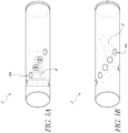
- the glucose sensor 2 is a solid optical fiber with a series holes 6A drilled straight through the sides of the optical fiber.
- the holes 6A are filled with the hydrogels 8.
- the series of holes 6A that are drilled through the glucose sensor 2 are evenly spaced horizontally and evenly rotated around the sides of the glucose sensor 2 to form a spiral or helical configuration.
- the series of holes 6A are drilled through the diameter of the glucose sensor 2.
- the glucose sensor 2 is a solid optical fiber with a series of holes 6A drilled through the sides of the fiber at an angle.
- the series of holes 6A drilled at an angle, which are filled with hydrogel 8, are evenly spaced horizontally and evenly rotated around the sides the glucose sensor 2.
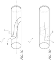
- the optical fiber comprises a groove 6B along the length of the optical fiber, wherein the groove 6B is filled with hydrogel 8.
- the depth of the groove 6B extends to the center of the optical fiber.
- the groove 6B spirals around the optical fiber.
- the groove 6B spirals around the optical fiber to complete at least one rotation.
- the glucose sensor 2 is a solid optical fiber with triangular wedges 6C cut from the fiber.
- the triangular wedge areas 6C are filled with hydrogel 8.
- the triangular wedges cut-outs 6C are evenly spaced horizontally and around the sides of the glucose sensor 2.
- all light traveling in the glucose sensor 2 is transmitted through at least one hole 6A or groove 6B filled with hydrogel 8.
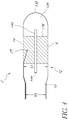
- the glucose sensor 2 comprises an optical fiber 10 having a distal end 12, an atraumatic tip portion 134 having a proximal end 136 and a distal end 138, a cavity 6 between the distal end 12 of the optical fiber 10 and the proximal end 136 of the atraumatic tip portion 134, and a rod 140 connecting the distal end 12 of the optical fiber 10 to the proximal end 136 of the atraumatic tip portion 134.
- a hydrogel 8 containing glucose sensing chemistry for example a fluorophore and quencher, fills the cavity 6. Covering the hydrogel filled cavity 6 is a selectively permeable membrane 14 that allows passage of glucose into and out of the hydrogel 8.
- the proximal portion of the sensor 2 comprises the proximal portion of the optical fiber 10.
- the diameter, D1, of the distal portion of the sensor 2 is greater than the diameter, D2, of the proximal portion of the sensor 2.
- the diameter D1 of the distal portion of the sensor 2 can be between about 0.0080 inches and 0.020 inches, while the diameter D2 of the proximal portion of the sensor 2 can be between about 0.005 inches to 0.015 inches.
- the diameter D1 of the distal portion of the sensor 2 is about 0.012 inches, while the diameter D2 of the proximal portion of the sensor 2 is about 0.010 inches.
- the glucose sensor 2 includes a temperature sensor 25, such as thermocouple or thermistor.
- the temperature sensor 25 can measure the temperature of the hydrogel 8 and glucose sensing chemistry system.
- the temperature sensor 25 is particularly important when the glucose sensing chemistry, such as a fluorophore system, is affected by temperature change.
- the fluorescence intensity emitted by the fluorophore system is dependent on the temperature of the fluorophore system.
- the hydrogels are associated with a plurality of fluorophore systems.
- the fluorophore systems comprise a quencher with a glucose receptor site.
- the quencher prevents the fluorophore system from emitting light when the dye is excited by an excitation light.
- the quencher allows the fluorophore system to emit light when the dye is excited by an excitation light.
- the emission produced by the fluorophore system varies with the pH of the solution (for example, blood), such that different excitation wavelengths (one exciting the acid form of the fluorophore and the other the base form of the fluorophore) produce different emissions signals.
- the ratio of the emission signal from the acid form of the fluorophore over the emission signal from the base form of the fluorophore is related to the pH level of the blood; the simultaneous measurement of glucose and pH is described in detail in U.S. Patent Publication No. 2008/0188722 .
- an interference filter is employed to ensure that the two excitation lights are exciting only one form (the acid form or the base form) of the fluorophore.
- optical sensing systems light sources, hardware, filters, and detection systems are described in detail in U.S. Publication No. 2008/0188725 . See e.g., FIG. 5 , wherein certain disclosures comprise at least two light sources.
- the light sources 301A, 301B generate excitation light that is transmitted through a collimator lens 302A, 302B.
- the resulting light from collimator lens 302A, 302B is transmitted to interference filters 303A, 303B.
- the resulting light from interference filters 303A, 303B is focused by focusing lens 304A, 304B into fiber optic lines 305A, 305B.
- fiber optic lines may be a single fiber or a bundle of fibers.
- the fiber optic line 309 may be a single fiber or a bundle of fibers.
- fiber optic lines 305A, 305B, 309 are bundled together at junction 306 and are connected at glucose sensor 307.
- the glucose sensor 307 comprises hydrogels 8.
- the emission light and the excitation light are reflected off the mirror 13 and into the fiber optic line 309.
- the fiber optic line 309 is connected to micro spectrometer 310 that measures the entire spectrum of light in the glucose measurement system 300.
- the micro spectrometer 310 may be coupled to a data processing module 311, e.g., the sensor control unit and/or receiver/display unit.
- the ratio of emission light over the corresponding excitation light is related to the concentration of glucose.
- the ratio of the emissions light (for example, the acid form) produced by the first excitation light over the emission light (for example, the base form) produced by the second excitation light is related to pH levels in the test solution, for example blood.
- the micro spectrometer is the UV/VIS Microspectrometer Module manufactured by Boehringer Ingelheim. Any micro spectrometer can be used. Alternatively, the micro spectrometer could be substituted with other spectrometer, such as those manufactured by Ocean Optics Inc.
- the ratiometric calculations require measurements of various light intensities. In certain disclosures, these measurements are determined by measuring the peak amplitudes at a particular wavelength or wavelength band. In certain disclosures, these measurements are determined by calculating the area under the curve between two particular wavelengths as for example with the output from a microspectrometer.
- FIGS. 6A and 6B another disclosure of an intravascular optical glucose sensor is illustrated; this sensor configuration is disclosed in greater detail in WO2009/019470 .
- sensors have been developed with internal reinforced walls, such as those depicted in FIGS. 6A and 6B.
- FIG. 6A shows a tube having a densely packed mesh 501A made of a first material and coated with an outer wall 502 of a second material.
- Three square cutouts 503 in the outer wall 502 of the tube arranged in a line can be seen in FIG. 6A , but cutouts of other shapes, positioned in other arrangements, are clearly feasible, depending on the embodiments.
- the mesh 501A shows a high density of filament crossovers. This disclosure therefore has an increased strength and a reduced porosity.
- the braid is able to provide strength to the sensor, while allowing the tubular structure to flex and be maneuvered to the correct sensing position.
- FIG. 6B depicts an disclosure in which the first material is in the form of a coil 501B which is coated with an outer wall 502 of the second material. Similar to FIG. 6A , three square cutouts 503 in the outer wall 502 of the tube arranged in a line can be seen in FIG. 6B , but cutouts of other shapes, positioned in other arrangements, are clearly feasible, depending on the embodiments.
- the coil 501B is densely packed, providing increased strength and reduced porosity in a similar manner to the disclosure depicted in FIG. 6A .
- the reinforced walls can be provided in a number of ways, for example by providing a braided tubular structure which contains the sensing apparatus, as described in International patent publication WO2004/054438 .
- the first material is in the form of a mesh 501A
- the density of filament crossovers may be varied in order to control the properties of the resulting tube.
- a high density mesh may have greater strength and a low density mesh a greater flexibility.
- Variation in mesh density will also vary the porosity of the mesh. This is significant at the location of the opening in the outer wall since the porosity of the mesh will control the speed of diffusion of the material to be tested into the tube. Variation in the tightness of a coil can provide a similar effect.
- the second material is used to coat the first material in order to form a continuous substantially impermeable outer wall 502 of the hollow tube.
- substantially impermeable means that the second material forms an effectively closed tube, which is impermeable to the ingress of material from outside the tube to inside the tube. Accordingly, until a portion of the second material is removed, the tube is effectively sealed along its length, except, in some disclosures, at its ends.
- Suitable materials for use as the second material generally include polymeric materials, more particularly polyesters, polyolefins such as polyethylene (PE), e.g. low density polyethylene (LDPE), fluoropolymers such as fluorinated ethylene propylene (FEP), polytetrafluoroethylene (PTFE) and perfluoroalkoxy polymer (PFA), polyvinylchloride (PVC), polyamides such as polyether block amide (PEBA), Pebax®, nylon and polyurethane.
- PETs and polyolefins are preferred due to their suitability for extrusion over the coil 501B or tubular mesh 501A.
- the selective removal of a portion of a polyester or polyolefin coating, e.g. by laser ablation, is also straightforward.
- Polyolefins are particularly preferred due to the ease of laser ablating these materials.
- the second material is first used to coat the coil or tubular mesh formed by the first material.
- the second material can either coat the outer surfaces of the first material, and in effect form a continuous substantially impermeable tube around the coil or tubular mesh formed by the first material, or the second material can entirely encapsulate the first material, effectively forming a tube of the second material in which is embedded the coil or tubular mesh formed by the first material.
- the second material can be applied to the first material by dip coating the coil or tubular mesh formed by the first material.
- the second material is probably a polyamide, which results in a very stiff tube.
- a tube of the second material can be provided, around which is formed the coil or tubular mesh of the first material. A further layer of the second material is then applied over the first material, resulting in the first material being sandwiched between two layers of the second material.
- the first material is metallic and the second material is polymeric.
- the second material is polymeric.
- further materials in the tubes disclosed herein it is possible to include further materials in the tubes disclosed herein.
- a radiopaque additive to enable the sensor incorporating the tube to be visible in vivo.
- radiopaque additives such as barium sulfate, bismuth subcarbonate, bismuth trioxide and tungsten can be added. Where present, these are preferably doped within the second material.
- a portion of the second material is selectively removed in order to generate at least one opening in a region of the outer wall, while retaining the first material in that region.
- the first material is present in the form of a coil or a tubular mesh, the first material does not form a completely closed tube. Accordingly, when the second material is removed in said region, this effectively forms a break in the continuous substantially impermeable wall of the tube.
- the second material simply coats the first material, it is necessary simply to remove the coating provided by this second material in the region where the opening is to be formed.
- the second material effectively encapsulates the first material, it is necessary to remove all of the second material which surrounds and encapsulates the first material in the region where the opening is to be formed.
- the chemical indicator system of the sensor is located adjacent to the opening formed by selective removal of the second material. This allows sensing of the environment in the region of the opening on the tube wall.
- the sensor is a glucose sensor
- glucose is able to pass from the blood vessel or other cavity where the sensor is introduced through the opening and into the tube where its presence can be detected and measured by the probe.
- the size of the opening in the outer wall will generally be between 1 and 400 mm 2 , for example between 25 and 225 mm 2 .
- the size of the opening must not be too small otherwise the blood or other substance into which the sensor is introduced will not be able to pass through the opening or will pass through in insufficient quantities for an accurate measurement to be made.
- the opening must also be large enough to allow positioning of the probe such that it is adjacent to the opening, even if it moves slightly when the sensor is introduced into the body.
- only one opening is generated in the tube wall, i.e. only one region of the second material is selectively removed.
- the opening extends only a portion of the way around the circumference of the tube.
- the opening extends around up to a maximum 75%, more preferably up to 50%, of the circumference of the tube.
- a plurality of openings can be generated in the tube wall, i.e. more than one region of the second material can be selectively removed.
- This disclosure allows for probes to be located at a number of points along the length of the tube, and for multiple measurements to be taken.
- a number of probes it is possible for a number of probes to be located within the tube, each tube being adjacent to a different opening within the tube wall.
- a single probe could be located within the tube and be provided with means for moving it from one opening to another opening, hence allowing measurements to be taken at a number of points along the length of the tube.
- Molecules of a biocompatible agent are attached to the surfaces of the medical device to improve biocompatibility, such as antithrombogenic agents like heparin, albumin, streptokinase, tissue plasminogin activator (TPA) or urokinase.
- the biocompatible agent may comprise molecules of both albumin and heparin.
- the molecules of a biocompatible material are joined to one another to form a film that is attached to a solid surface by a linking moiety.
- various surface treatments of the optical glucose sensor can be used, such as those disclosed in U.S. Patent Nos.
- the chemical linking moiety has the formula AX--B in which A represents a photochemically reactive group capable of bonding covalently to a solid surface; B represents a different reactive group capable desirably in response to specific activation to which group A is unresponsive, of forming a covalent bond to a biocompatible agent and X represents a relatively inert, noninterfering skeletal moiety joining groups "A", and "B", that is resistant to cleavage in aqueous physiological fluid.
- the physiological fluid referred to is such fluid with which X will come in contact (e.g., blood, interstitial fluid, etc.).
- group "A" of the linking moiety is covalently bound to the solid surface, with a sufficient population density to enable the molecules of the biocompatible agent to effectively shield the solid surface when the molecules are covalently bound to group "B" to provide a biocompatible effective surface.
- a biocompatible device includes a solid surface to which molecules of a biocompatible agent have been bound via the chemical-linking moiety as follows: solid surface-A residue-X--B residue-molecules of a biocompatible agent.
- the molecules of the biocompatible agent are selectively bound to the solid surface with a sufficient population density to provide a biocompatible effective surface using a chemically linking moiety that has the formula: in which R represents a selector group that is a member of a specific bonding pair and that is reactive to form a bond with a receptor forming the other member of the specific binding pair and carried by a selected biocompatible agent and A, and B represent the groups described above as A and B.
- X represents a relatively inert, non-interfering skeletal radical joining groups "A", "B” and “R” and sterically enabling group “B” to separate from group “R” by at least about 10 ⁇ .
- Groups "B” and “R” are preferably sterically distinct groups; that is, they may, during the course of thermal vibration and rotation separate by a distance of at least about 10 ⁇ .
- Group R a “selector” group, representing a member of a specific binding pair, commonly forms a bond, usually noncovalent, with the biocompatible agent at an epitopic or other binding site of the latter (which site typifies a "receptor” herein).
- the group “B”, which upon activation can covalently bond to the biocompatible agent may be sterically spaced from the group "R", thereby enabling the covalent bond to be formed at a site spaced from the receptor site.
- the selector receptor bond may be disassociated from the receptor site through breakage of a fragile bond between the selector group and the chemical linking moiety followed by removal of the selector by, e.g., dialysis, environmental changes (pH, ionic strength, temperature, solvent polarity, etc.) or through spontaneous catalytic modification of the selector group (as when the biocompatible agent is an enzyme), etc.
- the receptor thus is reactivated to permit subsequent reaction with members of the specific binding pair.
- specific binding pair refers to pairs of substances having a specific binding affinity for one another.
- substances include antigens and their antibodies, haptens and their antibodies, enzymes and their binding partners (including cofactors, inhibitors and chemical moieties whose reaction the enzymes promote), hormones and their receptors, specific carbohydrate groups and lectins, vitamins and their receptors, antibiotics and their antibodies and naturally occuring binding proteins, etc.
- the concept of employing specific binding pairs in analytical chemistry is well known and requires little further explanation. Reference is made to Adams, U.S. Pat. No. 4,039,652 , Maggio, et al, U.S. Pat. No. 4,233,402 and Murray, et al, U.S. Pat. No. 4,307,071 .
- X is preferably a C 1 -C 10 alkyl group such as polymethylene, a carbohydrate such as polymethylol, a polyoxyethylene, such as polyethylene glycol or a polypeptide such as polylysine.
- the reactive group B is preferably a group that upon suitable activation covalently bonds to proteinaceous or other biocompatible agents.
- groups are typified by thermochemical groups and photochemical groups, as described and exemplified in Guire, U.S. Pat. No. 3,959,078 .
- the photochemically reactive groups (A) may be typified by aryl, alkyl and acyl azides, oxazidines, isocyanates (nitrene generators), alkyl and 2 ketodiazo derivatives and diazirines (carbene generators), aromatic ketones (triplet oxygen generators), aromatic diazonium derivatives and numerous classes of carbonium ion and radical generators.
- Azidonitrophenyls, fluoroazido nitrobenzenes, and aromatic ketones form a preferred group due to their stability to chemical reaction conditions in the dark and their susceptibility to activation by light of wave lengths harmless to most biomaterials, to form short-lived reactive intermediates capable of forming covalent bonds in useful yield with most sites on the biomaterial.
- Nitrophenylazide derivatives (shown as including the X group) appropriate for use as photochemically reactive groups for the most part can be derived from fluoro-2-nitro-4-azidobenzene, and include 4-azido-2-nitrophenyl(ANP)-4-aminobutyryl, ANP-6-aminocaproyl, ANP-11-aminoundecanoyl, ANP-glycyl, ANP-aminopropyl, ANP-mercaptoethylamino, ANP-diaminohexyl, ANP-diaminopropyl, and ANP-polyethylene glycol.
- Aromatic ketones preferred for use as photochemically reactive groups include benzylbenzoyl and nitrobenzylbenzoyl.
- Thermochemical reactive groups are typified by and include nitrophenylhalides, alkylamino, alkylcarboxyl, alkylthiol, alkylaldehyde, alkylmethylimidate, alkylisocyanate, alkylisothiocyanate and alkylhalide groups.
- thermochemically reactive groups include carboxyl groups, hydroxyl groups, primary amino groups, thiol groups, maleimides and halide groups.
- N-oxysuccinimide carboxylic esters of such groups as 6-amino hexanoic acid and amino undecanoic acid, alkylthiol groups such as mercaptosuccinic anhydride and beta-mercaptopropionic acid, homocysteinethiolactones, and polyetheylene glycol derivatives are preferred.
- linking agents can also be used in the embodiments of the present disclosure, such as those disclosed in U.S. Patent No. 6,077,698 .
- a chemical linking agent comprising a di- or higher functional photoactivatable charged compound can be used.
- the linking agent preferably provides at least one group that is charged under the conditions of use in order to provide improved water solubility.
- the linking agent may further provide two or more photoactivatable groups in order to allow the agent to be used as a cross-linking agent in aqueous systems.
- the charge is provided by the inclusion of one or more quaternary ammonium radicals, and the photoreactive groups are provided by two or more radicals of an aryl ketone such as benzophenone.
- the thromboresistant agent may carry one or more latent reactive groups covalently bonded to them.
- the latent reactive groups are groups which respond to specific applied external stimuli to undergo active specie generation with resultant covalent bonding to an adjacent support surface.
- Latent reactive groups are those groups of atoms in a molecule which retain their covalent bonds unchanged under conditions of storage but which, upon activation, form covalent bonds with other molecules.
- the latent reactive groups generate active species such as free radicals, nitrenes, carbenes, and excited states of ketones upon absorption of external electromagnetic or kinetic (thermal) energy.
- Latent reactive groups may be chosen to be responsive to various portions of the electromagnetic spectrum, and latent reactive groups that are responsive to ultraviolet, visible or infrared portions of the spectrum are preferred. Latent reactive groups as described are generally well known.
- the azides constitute a preferred class of latent reactive groups and include arylazides, such as those disclosed in U.S. Patent No. 5,002,582 , for example phenyl azide and particularly 4-fluoro-3-nitrophenyl azide, acyl azides such as benzoyl azide and p-methylbenzoyl azide, azido formates such as ethyl azidoformate, phenyl azidoformate, sulfonyl azides such as benzenesulfonyl azide, and phosphoryl azides such as diphenyl phosphoryl azide and diethyl phosphoryl azide.
- arylazides such as those disclosed in U.S. Patent No. 5,002,582 , for example phenyl azide and particularly 4-fluoro-3-nitrophenyl azide, acyl azides such as benzoyl azide and p-methylbenzoyl azide, azido formates such as ethyl
- Diazo compounds constitute another class of latent reactive groups and include diazoalkanes (-CHN 2 ) such as diazomethane and diphenyldiazomethane, diazoketones such as diazoacetophenone and 1-trifluoromethyl-1-diazo-2-pentanone, such as t-butyl diazoacetate and phenyl diazoacetates, and beta-ketone-alpha-diazoacetates such as t butyl alpha diazoacetoacetate.
- diazoalkanes -CHN 2
- diazoketones such as diazoacetophenone and 1-trifluoromethyl-1-diazo-2-pentanone
- beta-ketone-alpha-diazoacetates such as t butyl alpha diazoacetoacetate.
- Peroxy compounds are contemplated as another class of latent reactive groups and include dialkyl peroxides such as di-t-butyl peroxide and dicyclohexyl peroxide and diacyl peroxides such as dibenzoyl peroxide and diacetyl peroxide and peroxyesters such as ethyl peroxybenzoate.
- the polymer molecules are covalently attached to the surfaces by means of residues of the latent reactive groups.
- Exemplary latent reactive groups are recited in U.S. Patent No. 5,002,582 .
- the polymers and oligomers used may have one or more latent reactive groups.
- the polymers have at least one latent reactive group per molecule with the ratio of reactive groups extended polymer length, in Angstroms, ranging from about 1/10 to about 1/700 and preferably from about 1/50 to 1/400.
- photoreactive latent reactive groups are for the most part aromatic and hence generally are hydrophobic rather than hydrophilic in nature.
- the latent reactive groups and the polymer molecules to which they are bonded may have substantially different solvophilic properties.
- the latent reactive groups may be relatively hydrophobic, whereas the polymer molecules may be relatively hydrophilic; when solution of the molecules is contacted with a relatively hydrophobic surface, it is believed that the latent reactive groups, being hydrophobic, tend to orient nearer the surface so as to improve bonding efficiency when the latent reactive groups are activated.
- the preferred latent reactive groups are benzophenones, acetophenones, and aryl azides.
- the loading density of polymers upon a surface may be improved by a process in which a latent reactive molecule (a molecule having a latent reactive group) is first brought into close association (as by means of a solvent solution) to a surface, and thereafter the polymer to be bonded to the surface is brought into contact with and is covalently bonded to the latent reactive molecule, as to a reactive group different from the latent reactive group. Thereafter, the latent reactive groups may be activated to cause them to covalently bond to the surface to thereby link the polymers to the surface.
- a latent reactive molecule a molecule having a latent reactive group
- polymer chains may be provided upon a surface or other substrate by first covalently bonding to the substrate through a latent reactive group a monomer, oligomer or other reactive chemical unit.
- a monomer, oligomer or other reactive chemical unit to the thus bonded reactive units are covalently bonded monomers or oligomers in a polymerization reaction or polymers via covalent bonding (grafting) of the reactive units onto the polymer chains.
- the reactive chemical units of the invention carry covalently bonded thereto latent reactive groups as described herein for covalent attachment to a non pretreated surface or other substrate.
- These molecules are characterized as having reactive groups capable of covalent bonding to polymer molecules of a polymer having the desired characteristics, or of entering into a polymerization reaction with added monomers or oligomers to produce polymer chains having the desired characteristics.
- Reactive chemical molecules capable of covalently bonding to polymer molecules include not only monomers and oligomers of various types but also molecules having such functional groups as carboxyl, hydroxyl, amino, and N-oxysuccinimide, such groups being reactive with reactive groups carried by the polymer chain to bond to the chain.
- the reactive chemical molecules are preferably monomers or oligomers and most preferably are ethylenically unsaturated monomers capable of entering into an addition polymerization reaction with other ethylenically unsaturated monomers.
- Particularly preferred are the acrylate and methacrylate monomers which are the esterification products of acrylic or methacrylic acid and hydroxy-functional latent reactive groups. Examples of such molecules include 4-benzoylbenzoyl-lysyl-acrylate.
- reactive chemical units bearing latent reactive groups one may first coat a surface or other substrate with a solvent solution of such molecules. Upon removal of solvent, the application of an appropriate external stimulus such as U.V. light will cause the molecules to covalently bond, through the latent reactive groups, to the substrate. The substrate may then be appropriately contacted with a solution containing the desired polymer, monomer or oligomer molecules to cause bonding to these molecules.
- the reactive chemical unit molecule is carboxyl functional, it may be reactive with, and covalently bonded to, an appropriate hydroxyl-functional polymer such as dihydroxy polyethylene glycol.
- the substrate to which the molecule is covalently bonded may be contacted with a solution of addition-polymerizable monomers such as hydroxyethyl methacrylate and a free-radical addition polymerization initiator such as dibenzoyl peroxide under addition polymerization conditions to result in the growth of polymer chains from the monomer molecules bound covalently to the substrate.
- addition-polymerizable monomers such as hydroxyethyl methacrylate
- a free-radical addition polymerization initiator such as dibenzoyl peroxide
- the thromboresistant coating can adhere better by surface modification of the medical device by adsorbing a layer of a polyamine having a high average molecular weight on to the surface.
- the polyamine is stabilised by cross-linking with crotonaldehyde, which is a mono-aldehyde having a C-C double bond in conjugation with the aldehyde function.
- crotonaldehyde which is a mono-aldehyde having a C-C double bond in conjugation with the aldehyde function.
- one or more alternating layers of an anionic polysaccharide and the cross-linked polyamine, followed by a final layer of the said polyamine, not cross-linked may be adsorbed onto the first layer of cross-linked polyamine, whereby a surface modification carrying free primary amino groups is achieved.
- the thromboresistant coating is made by bringing the substrate into contact with an aqueous solution of the polyamine at pH 8-10, for example pH 9.
- the concentration of the initial polyamine solution will range from 1-10% by weight, especially 5% by weight, 1 ml of which may be diluted to a final volume of 500-2000 ml, especially 1000 ml.
- This final solution may also comprise from 100-1000 ⁇ l, especially 340 ⁇ l crotonaldehyde.
- the substrate will be treated first with a solution of polyamine of said concentration and pH, and then with a solution of the crotonaldehyde of the said concentration and pH.
- the temperature is not critical, so it is preferred for the treatment to be at room temperature.
- the substrate After rinsing with water, the substrate is treated with a solution of an anionic polysaccharide, containing from about 10 toabout 500 mg, preferably about 100 mg of the polysaccharide in a volume of 1000 ml.
- This step is executed at a temperature in the range of 40°-70°C., preferably about 55°C and pH 1-5, preferably about pH 3.
- the substrate may be treated with a polyamine solution having a concentration 1-20 times, preferably 10 times, that mentioned above, at the said temperature and pH.
- the polyamine will preferably be a polymeric aliphatic amine, especially polyethylene imine having a high average molecular weight, but any polyamine having a high average molecular weight and carrying free primary amino groups may be used.
- the anionic polysaccharide will preferably be a sulfated polysaccharide.
- the aminated surface may optionally be further stabilized by reduction with a suitable reducing agent such as sodium cyanoborohydride.
- the modified surface according to present invention has free primary amino groups by which chemical entities may be bound either ionically or covalently. Also aldehyde containing chemical entities may be bound by formation of Schiff's bases, eventually followed by a stabilization reaction such as a reduction to convert the Schiffs bases to secondary amines. Further examples are disclosed in U.S. Patent No. 5,049,403 .
- a composition is prepared to include a solvent, a combination of complementary polymers dissolved in the solvent, and the bioactive agent or agents dispersed in the polymer/solvent mixture.
- the solvent is preferably one in which the polymers form a true solution.
- the pharmaceutical agent itself may either be soluble in the solvent or form a dispersion throughout the solvent.
- sensors can be difficult to coat with conventional anticoagulants, or anti-thrombogenics, e.g., heparin, to obtain a suitable anticoagulant coating, which is sufficiently stable, long-lasting, and active for preferred intravascular applications, and yet is sufficiently invisible to analytes of interest and non-interfering with the sensor chemistry to allow reliable and sufficiently long-lasting operation.
- anticoagulants or anti-thrombogenics, e.g., heparin
- Various issues can arise relating to the suitability of a particular coating including, for example, stability of the coating during manufacturing and handling of the sensor, resistance of the coating to removals during use, such as by solubilization, reaction, etc., resistance to diffusion through the coating of analytes of interest, and interaction between species in the coating and the sensor technology, whether by hydrolysis of detectable species from the coating or by other means.
- Coating materials comprising heparin are preferred, but other polysaccharide and biologically derived materials and analogs can be utilized as well, either with heparin or in place of heparin.
- Preferred methods of applying the coating include application of a heparin-quaternary ammonium complex in isopropanol to a sensor wetted with water or water/surfactant under vacuum, but other suitable methods of applying a coating can also be successfully employed, such as application of a heparin-quaternary ammonium complex from combinations of solvents, such as nonpolar solvents and polar solvents; sequential application of quaternary ammonium compound and heparin, such as to form a heparin-quaternary ammonium complex in-situ; covalently bonding heparin molecules to the surface of the sensor, including methods for attaching individual ends of heparin molecules to the surface such as described by Carmeda AB (Upplands Vasby, Sweden); and application of cross-linked forms of hepar
- a coating of heparin or a heparin containing material can be applied to at least a portion of the sensor surface to limit or prevent thrombus formation.
- application of such a coating can be difficult due to problems of adhesion where the coating will not properly adhere to the surface initially or will tend to detach or dissolve from the surface upon use.
- the coating detaches upon use can be particularly problematic due to the possibility of particulate impurities being released into the bloodstream and the possibility that these can result in plugging of small blood vessels.
- detachment or dissolution of heparin coating material can result in therapeutic or sub-therapeutic dosing of the patient with an anticoagulant material.
- adhesion problems can be particularly pronounced when applied to certain types of materials, especially plastics such as polyolefins, fluoropolymers, polycarbonate.
- plastics such as polyolefins, fluoropolymers, polycarbonate.
- polyolefins and fluoropolymers in particular are especially difficult to adhere materials to, as evidenced by the difficulty and limited strength that is typically achieved when these plastics are glued.
- a coating comprising heparin and benzalkonium can be effectively applied and will maintain an acceptably stable and active coating over polymeric surfaces of analyte sensors disclosed herein, including polymeric surfaces such as polyolefins, fluoropolymers, polycarbonate, porous polymeric surfaces, and porous polymeric surfaces on sensors incorporating immobilizing polymeric matrices, while still maintaining acceptable functionality of the analyte sensor.
- the porous surfaces capable of maintaining an acceptably stable and active coating comprising heparin and benzalkonium are more specifically described as microporous, nanoporous, or mesoporous.
- the coating comprising heparin and benzalkonium may include pharmaceutical grade heparin, such as heparin sodium or heparin calcium as described in the U.S. Pharmacopeia, revised June 18, 2008, however, other grades and forms of heparin can be utilized in various applications, including instances where pharmaceutical regulations do not apply.
- Preferred grades of heparin can have an average molecular weight of about 12 to about 15kDa, however, individual strands can have molecular weights as high as about 40 kDa or 50kDA or even higher, and as low as about 5 kDa or 3 kDa or even lower.
- heparin with average molecular weights higher or lower than about 12 to about 15 kDa can be successfully utilized, such as those as high as about 20 or 30 kDa or as low as about 7 or 10 kDa.
- the coating comprising heparin and benzalkonium may include molecules of benzalkonium chloride having alkyl groups of about 1 to about 5 carbons for two of the R-groups and an alkyl group of about six to about 22 carbons for the third R-group, either as a single pure compound or as a combination of compounds with differing R-groups.
- grades of benzalkonium chloride include those having compounds and mixtures of compounds having primarily two methyl groups and an alkyl group of about six to about 22 carbons, or more preferably two methyl groups and an alkyl group of about 10 to about 18 carbons as the R-groups.
- ammonium complexes can be used, e.g., particular alkylbenzyl dimethyl ammonium cationic salts, which can be used in high loading concentrations with heparin to form coatings, as disclosed in U.S. Patent No. 5,047,020 to Hsu .
- Hsu found that commercially available benzalkonium chloride may comprise a mixture of alkylbenzyldimethylammonium chloride of the general formula, [C 6 H 5 CH 2 N(CH 3 ) 2 R]Cl, in which R represents a mixture of alkyls, including all or some of the groups comprising C8 and greater, with C12, C14 and C16 comprising the major portion.
- the composition breaks down to more than 20% C14, more than 40%, C12 and a less than 30% mixture of C8, C10 and C16.
- preferred heparin/quaternary ammonium complexes have at least about 50 weight percent of the organic cationic salt, and preferably from 60 to 70 weight percent. Hsu found that optimum results were achieved with complexes consisting of cetalkonium heparin and/or stearylkonium heparin and mixtures thereof.
- Hsu teaches that coatings for medical devices consisting of complexes of cetalkonium heparin and/or stearylkonium heparin and mixtures thereof, exhibit "vastly superior hydrophobicity and surface adhesion over the presently and most commonly used complexes of heparin and benzalkonium chloride.” Accordingly, in another aspect of the disclosure, other heparin/quaternary ammonium complexes besides those comprising benzalkonium, like those disclosed by Hsu, may be used to coat and render thromboresistant the glucose sensors disclosed herein.
- the present disclosure provides a compound comprising a nonpolymeric core molecule comprising an aromatic group, the core molecule having attached thereto, either directly or indirectly, one or more substituents comprising negatively charged groups, and two or more photoreactive species, wherein the photoreactive species are provided as independent photoreactive groups.
- the first and second photoreactive species of the present coating agent can, independently, be identical or different.
- the core is provided as the residue of a polyhydroxy benzene starting material (e.g., formed as a derivative of hydroquinone, catechol, or resorcinol), in which the hydroxy groups have been reacted to form an ether (or ether carbonyl) linkage to a corresponding plurality of photogroups.
- a coating agent of this invention further comprises one or more optional spacers that serve to attach a core molecule to corresponding photoreactive species, the spacer being selected from radicals with the general formula: wherein n is a number greater or equal to 1 and less than about 5, and m is a number greater or equal to 1 and less than about 4.
- such coating agents are selected from the group 4,5-bis(4-benzoylphenylmethyleneoxy)benzene-1,3-disulfonic acid di(potassium and/or sodium) salt, 2,5-bis(4-beizoylphenylmethyleneoxy)benzene-1,4-disulfonic acid di(potassium and/or sodium) salt, 2,5-bis(4-benzoylphenylmethyleneoxy)benzene-1-sulfonic acid monopotassium and/or monosodium salt.
- Suitable core molecules used in the present invention include nonpolymeric radicals having a low molecular weight (e.g., 100-1000 MW). Suitable core molecules provide an improved combination of such properties as coating density, structural stability, ease of manufacture, and cost. Further, core molecules can be provided with water soluble regions, biodegradable regions, hydrophobic regions, as well as polymerizable regions. Examples of suitable core molecules include cyclic hydrocarbons, such as benzene and derivatives thereof.
- the type and number of charged groups in a preferred coating agent are sufficient to provide the agent with a water solubility (at room temperature and optimal pH) of at least about 0.1 mg/ml, and preferably at least about 0.5 mg/ml, and more preferably at least about 1 mg/ml.
- a water solubility at room temperature and optimal pH
- coating agent solubility levels of at least about 0.1 mg/ml are generally adequate for providing useful coatings of target molecules (e.g., polymer layers) on surfaces.
- the coating agent can thus be contrasted with many coating agents in the art, which are typically considered to be insoluble in water (e.g., having a comparable water solubility in the range of about 0.1 mg/ml or less, and more often about 0.01 mg/ml or less). For this reason, conventional coating agents are typically provided and used in solvent systems in which water is either absent or is provided as a minor (e.g., less than about 50% by volume) component.
- Suitable charged groups include salts of organic acids (e.g., sulfonate, phosphonate, and carboxylate groups), as well as combinations thereof.
- a preferred charged group for use in preparing coating agents used in the present invention is a sulfonic acid salt, e.g., derivatives of SO 3 - in which the counterion is provided by the salts of Group I alkaline metals (Na, K, Li ions) to provide a suitable positively charged species.
- photoreactive species in the form of photoreactive aryl ketones are preferred, such as acetophenone, benzophenone, anthraquinone, anthrone, and anthrone-like heterocycles (i.e., heterocyclic analogs of anthrone such as those having N, O, or S in the 10-position), or their substituted (e.g., ring substituted) derivatives.
- preferred aryl ketones include heterocyclic derivatives of anthrone, including acridone, xanthone, and thioxanthone, and their ring substituted derivatives. Particularly preferred are thioxanthone, and its derivatives, having excitation energies greater than about 360 nm.
- ketones are preferred since they are readily capable of undergoing the activation/inactivation/reactivation cycle described herein.
- Benzophenone is a particularly preferred photoreactive moiety, since it is capable of photochemical excitation with the initial formation of an excited singlet state that undergoes intersystem crossing to the triplet state.
- the excited triplet state can insert into carbon-hydrogen bonds by abstraction of a hydrogen atom (from a support surface, for example), thus creating a radical pair. Subsequent collapse of the radical pair leads to formation of a new carbon-carbon bond.
- a reactive bond e.g., carbon-hydrogen
- the ultravieolet light-induced exitation of the benzophenome group is reversible and the molecule returns to ground state energy level upon removal of the energy source.
- Photoactivatible aryl ketones such as benzophenone and acetophenone are of particular importance inasmuch as these groups are subject to multiple reactivation in water and hence provide increased coating efficiency.
- the coating processes disclosed herein include: 1) direct coating of the heparin complex by straight application, as in the case of dip coating, as well as 2) indirect coating, as in the case of sequential applications of a quarternary ammonium salt plus surfactant and the ionic heparin.
- Suitable methods for applying a coating comprising heparin and benzalkonium may include multistep layering techniques as well as single step application of heparin complexes.
- pretreatment methods are used, such as soaking the sensors in sodium heparin solutions.
- adhesion can be facilitated by chemically treating the surfaces in order to provide hydroxyl groups on or near the surface thereof.
- exemplary chemical surface treatments include such known procedures as chemical etching, surfactant adsorption, coextrusion, plasma discharge, surface oxidation or reduction, radiation activation and oxidation, and surface grafting with materials such as polyvinyl alcohol, poly(2-hydroxyethyl methacrylate) and the like.
- Bulk modifications of the substrate surface can also be accomplished in order to provide active hydrogens. Examples of conventional modifications of this type include blending with polymers having active hydrogens, partial degradation of polymers, end group modification, monomer functionalization, oxidation, reduction, copolymerization, and the like.
- a three-dimensional highly crosslinked matrix containing aminosilanes is formed on the medical device surface.
- the aminosilane is cured, crosslinked or polymerized in place on the surface to be rendered thromboresistant. This is carried out in a manner such that a three-dimensional matrix is formed.
- the matrix can be either an aminosilane homopolymer or a copolymer, including a graft copolymer, of an aminosilane with another silane that is not an aminosilane.
- Representative aminosilanes include 3-aminopropyltrimethoxysilane, 3-aminopropyltriethoxysilane, 2-aminoundecyltrimethoxysilane, aminophenyltrimethoxysilane, N-(2-aminoethyl-3-aminopropyl)trimethoxysilane, and trimethoxysilylpropyldiethylenetriamine.
- Aminosilanes of this type can be used alone in order to form a homopolymer matrix.
- certain aminosilanes are trifunctional and provide a highly crosslinked matrix.
- the hydrophilicity can be reduced, when desired, by combining the hydrophilic aminosilane with a less hydrophilic silane that is not an aminosilane.
- Other methods and coating agents are also known in the art, including U.S. Patent No. 5,053,048 , 4,973,493 , 5,049,403 .
- a coating comprising heparin and benzalkonium is applied by first wetting the sensor surface with water or a combination of water and surfactant.
- Preferred surfactants include anionic surfactants, however other surfactants such as cationic surfactants or non-ionic surfactants may also be successfully employed in some embodiments.
- suitable surfactants include sodium laurel sulfate, sodium dodecyl sulfate, ammonium lauryl sulfate, sodium laureth sulfate. The wetted sensor is then treated with an alcoholic solution of heparin-quaternary ammonium complex.
- the alcoholic solution comprises isopropanol, however other alcohol based solutions may be used as well, depending on the embodiment.
- Preferred solutions of isopropanol may include about 1 to about 99 % (wt.) of heparin-benzalkonium complex in isopropanol, including 5%, 10%, 25%, 50%, 75%, 90%, and 95% (and also including ranges of weight percentages bordered on each end by these recited weight percentages).
- One preferred solution of heparin-benzalkonium in isopropanol is manufactured by Celsus Laboratories, Inc.
- the wetted sensor can be dipped in the heparin-benzalkonium solution, or it can be sprayed onto the surface of the sensor or applied by another suitable technique.
- the sensor with coating solution applied is then dried. Additional coating material, such as to improve consistency of a coating or to thicken a coating, can be applied by dipping, spraying or other suitable means.
- preferred methods include those where the sensor is exposed to the heparin-benzalkonium solution for only a limited time, such as less than one minute, or less than about 30 seconds or about 10 seconds or even about 1 or 2 seconds, such as by dipping the sensor into the solution for only about a second (and also including time intervals bordered on the high end and the low end by the recited durations such as dipping the sensor into the solution for between 10 and 30 seconds).
- a limited time such as less than one minute, or less than about 30 seconds or about 10 seconds or even about 1 or 2 seconds, such as by dipping the sensor into the solution for only about a second (and also including time intervals bordered on the high end and the low end by the recited durations such as dipping the sensor into the solution for between 10 and 30 seconds).
- short time intervals can prevent undesirable results, such as excessive solubilization of material from the sensor surface or excessive dehydration of the sensor.
- longer time periods can successfully be utilized by, for example, increasing the concentration of heparin-benzalkonium concentration of the solution or by supplementing the solution with additional benzalkonium material or heparin material, or by adjusting the pH, or ionic strength of the solution.
- the sensor can be rehydrated as needed or desired by application of water or a combination of water and surfactant and/or solvent.
- Suitable multistep layering techniques include those techniques where an heparin and benzalkonium are applied by a process comprising application of a suitable form and grade of benzalkonium chloride followed by application of a suitable form and grade of heparin.
- Any suitable solvent or combinations of solvents can be used for heparin, such as water or aqueous alcohol, and for benzalkonium chloride, such as nonpolar organic solvents (for example, toluene, petroleum ether, etc.).
- Preferred heparin solutions include those comprising heparin in a weight percentage of about 0.05%, 1%, 5%, 10%, 25%, 50%, 75%, 90%, and 95% (and also including ranges of weight percentages bordered on each end by these recited weight percentages). In certain such disclosures, a preferred heparin solution comprises a weight percent of heparin between about 0.05% to about 1%.
- Preferred benzalkonium chloride solutions include those comprising benzalkonium in a weight percentage of about 0.05%, 1%, 5%, 10%, 20%, 25%, 50%, 75%, 90%, and 95% (and also including ranges of weight percentages bordered on each end by these recited weight percentages). In certain such disclosures, a preferred benzalkonium chloride solution comprises a weight percent of benzalkonium chloride between about 1.0% to about 20%.
- Single step application of heparin complexes can comprise applying a solution comprising heparin and benzalkonium of a suitable grade and form to the sensor, such as is described in U.S. Patent No. 5,047,020, to Hsu .
- the solution may include benzalkonium chloride.
- Suitable solvents for the heparin and benzalkonium include those comprising polar organic solvents, alone or as mixtures, such as alcohols (e.g. isopropanol), halogenated solvents (e.g. trifluoro-trichloro ethane), etc.
- the solution to be applied to the polymeric surface may include heparin and benzalkonium in a combined weight percentage of 0.1%, 1%, 5%, 10%, 25%, 50%, 75%, or about 90% of the total weight of the solution (also including ranges of weight percentages bordered on each end by these recited weight percentages).
- a solution may contain between about 0.1% to about 75% heparin/benzalkonium by weight.
- successive layers of heparin/benzalkonium complex can be applied to the surface of the sensor, for example, to build up a coating having a desired thickness and/or durability.
- the distal portion of a pre-wetted sensor is dipped in a solution comprising heparin and benzalkonium in isopropanol, preferably for about 0.1 to about 30 seconds, and more preferably for about 1 to about 10 seconds, and even more preferably for about 1 second.
- the dipped sensor is subsequently air dried, preferably for at least about 10 seconds, and more preferably for about 0.5 minutes to about 10 minutes, and even more preferably for about 1 minute.
- heparin/benzalkonium coating and drying steps are repeated in accordance with various embodiments, preferably from about 1 to about 20 times, or more preferably from about 2 to about 10 times, or even more preferably from about 3 to about 8 times, and even more preferably still from about 4 to about 6 times.
- a sustained release of heparin from the sensor surface into the surrounding vessel is achieved by soaking the sensor.
- the sensor which optionally contains a hydrogel underneath the optional microporous membrane, is soaked in a solution of heparin for infusion of heparin into the swollen hydrogel.
- a solution of heparin for infusion of heparin into the swollen hydrogel.
- an aqueous solution of at least about 10% sodium heparin is used.
- an aqueous solution of at least about 20% sodium heparin is used.
- an aqueous solution of at least about 30% sodium heparin is used.
- other organic solvents and other forms of heparin may be used.
- the sodium heparin solution is in phosphate buffered saline of about pH 5.
- the sensor is removed from the solution and allowed to dry.
- the sensor is soaked for at least about 1 hour. In a preferred embodiment, the sensor is soaked for about 2 hours. In one disclosure, the sensor is soaked for at least about 3 hour.
- the hydrogel re-swells in the bloodstream thus releasing the heparin gradually over time.
- Additional steps can be utilized as necessary, such as, for example, cleaning the surface of the sensor with suitable agents such as solvents, surfactants, etc. and/or drying the coating, such as with a gas stream, or with heat, or with a heated gas stream, or with one or more dehydrating agents.
- suitable agents such as solvents, surfactants, etc.
- drying the coating such as with a gas stream, or with heat, or with a heated gas stream, or with one or more dehydrating agents.
- heparin-based coating includes covalently bonding heparin, or a heparin derivative, to the surface of the sensor or to an intermediate material applied to the surface of the sensor.
- Suitable techniques include those that covalently bond the end of a heparin molecule to the surface of the sensor or an intermediate, such as the techniques utilized by Carmeda AB (Upplands Vasby, Sweden).
- Suitable methods also include those utilizing photoimmobilization to attach heparin, or a heparin derivative to the surface of a sensor or an intermediate material applied to the surface of the sensor, such as are described herein and by Surmodics (Eden Prairie, MN), as well as those depositing heparin complexes with polar and nonpolar solvents, such as are described in U.S. Patent No. 6,833,253 to Roorda, et al. WORKING EXAMPLES Example 1. Application of Thromboresistant Coating (not part of present invention)
- An optical glucose sensor as described above was prepared for coating with benzalkonium/heparin by immersing the portion of the sensor to be coated in a pH 3 phosphate buffered saline solution (although it is feasible to use many types of aqueous buffer solutions or even just water).
- a coating solution of 1.5% (by weight) benzalkonium heparin in isopropanol was added to a test tube. After equilibrating in the buffered saline solution, the distal end portion of the sensing end of the sensor was immersed in the benzalkonium heparin solution and immediately removed (with the time of immersion in the benzalkonium heparin solution being approximately one second). The wet sensor was allowed to air dry for approximately 1 minute, resulting in a coating of benzalkonium heparin on the sensor surface.
- a sensor blank was prepared from a polyethylene microporous membrane (of 0.017 inch outside diameter) surrounding a poly(methyl methacrylate) optical fiber (of 0.010 inch diameter).
- the polyethylene microporous membrane was obtained from Biogeneral 9925 Mesa Rim Road, San Diego CA 92121-2911).
- the distal end of the sensor blank (the end to be coated) is heat welded to a rounded polyethylene plug. The other end is sealed with a silicone backfill.
- the distal end was then immersed in the buffered saline solution of Example 1 for about 18 hours (although a shorter time interval would also have been suitable).
- the distal end of the sensor blank was immersed in the coating solution of Example 1 and subsequently air dried as in Example 1. The steps of immersing in the coating solution and air drying were repeated four times.
- Coated sensors and coated sensor blanks prepared as described in Examples 1 and 2, each having five dip coats of heparin/benzalkonium applied, were subjected to handling tests as follows.
- Sensors consisted of a 1.3-inch long hollow, microporous High Density Polyethylene (HDPE) membrane (0.017 inches O.D., Biogeneral 9925 Mesa Rim Road, San Diego CA 92121-2911, this is a custom part) butt-welded to a 1.0-inch long, smooth (nonporous) HDPE tube.
- the microporous end was heat-welded to a rounded polyethylene plug.
- Inside of the hollow assembly was threaded a 0.010 inch PMMA optical fiber
- the smooth HDPE end was filled with silicone backfill up to, but not including, the microporous membrane.
- the area between the PMMA optical fiber and the hollow microporous membrane was filled with a dimethyl acrylamide gel which also contained covalently-bound fluorescent dye and quencher.
- the sensor was prepared for application of the coating comprising heparin and benzalkonium by immersing the distal ("sensor") end in an aqueous solution of phosphate buffered saline as described in Example 1 for about 18 hours (although this amount of time may not be necessary). The sensor was then immersed in the heparin/benzalkonium solution and air dried as described in Example 1. The immersion and drying steps were repeated 4 times.
- the sensors and sensor blanks were prepared for the handling tests by staining with toluidine blue. Specifically, the sensors and sensor blanks were pulled through the silicone rubber seal, and then dipped in a 0.04% solution of toluidine blue in water for 1 minute, rinsed with water and allowed to air dry for 30 minutes.
- Toluidine blue stains heparin a purple color, and so a darker purple color tends to indicate a higher concentration of heparin than a lighter purple color or no purple color at all.
- the stained sensors and sensor blanks were subjected to the following handling tests and subsequently visually examined under 20X magnification to discern voids and thinness in the heparin coating indicated by the lightening of the toluidine stain. The results are described below as well.
- a coated sensor was placed into a sensor housing assembly, consisting of a polyurethane tubing and sealed with a parylene-coated silicone rubber seal.
- the housing assembly was filled with pH 7.4 phosphate buffered saline and the sensor was soaked in the housing for 1 hour at room temperature.
- the nonporous polyethylene section displayed (under magnification) clear signs of damage to the heparin coating, with apparent scrapes and voids in the purple stain.
- the microporous membrane section looked unaffected, with a consistent and smooth purple stain.
- Abrasion A sensor was soaked in pH 7.4 phosphate buffered saline for 1 hour at room temperature, then rubbed vigorously with a wet nitrile glove for one minute. It was then stained with toluidine blue. Under magnification, the nonporous polyethylene section was almost completely devoid of purple stain, indicating a total loss of the heparin coating. The microporous membrane section looked to be diminished and somewhat patchy, although there was still a strong purple color along the entire length. It should be noted that the handling in this portion of the test was very extreme.
- Test condition Microporous membrane stain Nonporous polyethylene stain Storage in phosphate buffered saline solution Dark, even purple stain Lighter color, less even Storage in sensor housing assembly Dark, even purple stain Clear signs of abrasion, large voids in purple stain Abrasion Lighter purple stain, still evenly coated Purple stain completely removed Sonication with isopropanol Lighter purple stain, still evenly coated Purple stain completely removed Control (no handling tests) Dark, even purple stain Dark, even purple stain stain
- 12 GLUCATH® sensors with a benzalkonium/heparin coating and 12 BD L-Cath PICC lines (outside diameter 0.037 cm, 0.0145 inches; polyurethane) as controls without coating were prepared for insertion into the cardiovascular system of four sheep.
- the coated GluCath sensor was constructed of a fluorophore/quencher indicator system embedded in a hydrophilic acrylic matrix, as described in U.S. Patent Application No. 12/026,396 .
- the benzalkonium heparin coating was applied as described in Example 3.
- Sensors and control catheters were inserted into the left and right jugular veins and left and right cephalic veins, with the sensor on one side and the control catheter on the other of the same sheep. After 25 hours, two sheep were euthanized and the sensors and controls were surgically exposed and examined by incising and reflecting the skin and surrounding tissues overlying the test article and vein, and then opening the vein longitudinally taking care not to disturb the sensor or catheter or any cellular accumulation or debris on the test articles or in the veins. After 22 additional hours (47 hours elapsed time), two additional sheep were euthanized and the sensors surgically exposed and examined as described above.
- GluCath sensors were soaked in a 30% solution of sodium heparin in pH 5 phosphate buffered saline for two hours to saturate the hydrogel. After removal from the soak solution, the sensors were dip-coated with heparin benzalkonium in isopropyl alcohol to coat the outer surface. To serve as controls, other sensors which had not undergone the sodium heparin soaking step were also heparin benzalkonium dip-coated. After air drying overnight, the sensors were subjected to flowing buffer (pH 7.4 phosphate buffered saline at 37°C) for up to 48 hours.
- flowing buffer pH 7.4 phosphate buffered saline at 37°C
- the sensors were removed from the buffer and tested for heparin activity using a chromogenic anti-FXa activity assay.
- the results, shown in Figure 8 showed that the heparin-soaked sensors retained higher levels of activity than the control sensors at each time point.
- PES membranes To a 13 ⁇ 100 mm borosilicate culture tube was added 3 mL of Boc-amido-dPEG4-acid (4°C), 3 mL of 0.2M NHS (4°C), and 3 mL of 0.2M EDC (4°C) and the solution was stored at 4°C for 15 min. Eight PES membranes were glued to polyimide tubing and inserted into the solution through a septum and stored at 4°C for 15h. The excess reagent was removed and the membranes were washed with water (3 ⁇ 9 mL). In a separate tube, the membranes were treated with 0.275M HCl in 70% EtOH/H 2 O for 3 h.
- HDPE membranes To a 12 ⁇ 75 mm borosilicate culture tube was added 2 mL of Boc-amido-dPEG4-acid (4°C), 2 mL of 0.2M NHS (4°C), and 2 mL of 0.2M EDC (4°C) and the solution was stored at 4°C for 15 min. Five HDPE membranes were added to the solution and the mixture was stored at 4°C for 15 h. The excess solution was removed and the membranes were washed with water (3 ⁇ 6 mL). In a separate tube, the membranes were treated with 0.275M HCl in 70% EtOH/H 2 O for 3 h. The excess solution was removed and the membranes were washed with water (3 ⁇ 4 mL).
- radio frequency glow discharges fed with NH 3 may be used to attach chemical groups onto polymers that are suitable for biomolecule immobilization.
- Condition D was the most aggressive treatment resulting in the greatest amount of amine functionalization on the surface of the membrane without damaging the integrity of the membrane. Proof of surface modification was established by staining with Porphyrin-CO 2 H or Bradford reagent. As indicated in Figure 9 , the untreated mpms (controls) do not change color when dipped in staining solution, whereas the plasma treated samples become yellow or blue depending on the stain. The optimum conditions were chosen based on the intensity of the stain; condition D was selected for all future experiments.
- the PEG-spacer is thought to allow for more degrees of freedom for heparin.
- the PEG lines up on the surface in a vertical arrangement and leaves room for heparin to move about with less restriction than if it was bound directly to the surface. This is believed to improve the heparin activity.
- FIG. 10 examples of heparin bound to the surface of a biomaterial are given in Figure 10 .
- Panel A depicts Hep ionically bound to the surface
- B describes Hep ionically bound to a counterion
- C represents the current HBAC (Surmodics) method where Hep physically coats the surface
- D and E represent single point attachment of heparin with and without a spacer
- F illustrates Hep dispersed in a hydrophobic polymer
- G illustrates Hep immobilized as a conjugate with albumin.
- heparin When heparin is attached at a single point (as in D, E, and G), it has more degrees of freedom and retains its activity and ability to bind antithrombin. In some cases, heparin is attached from a single site in the heparin to a single site on an amino-functionalized membrane or to a spacer. As it relates to our system, direct attachment of heparin (D) and PEG-spaced attachment (E) can be considered attempts at single point attachment. In these cases, heparin is attached from a single site in the heparin molecule to a single site on an amino-functionalized membrane via a spacer. True single point attachment is obtained by chemically modifying heparin with periodate, which is the approach that Carmeda AB (Upplands Vasby, Sweden) uses. The strategy disclosed herein is novel and simpler.
- both PES membranes have a higher long term activity (24 h wash) then HDPE.
- PES2 has higher initial activity (after brine wash). This demonstrates that PES is a better substrate for covalent attachment of heparin.
Landscapes
- Health & Medical Sciences (AREA)
- Life Sciences & Earth Sciences (AREA)
- Engineering & Computer Science (AREA)
- Chemical & Material Sciences (AREA)
- Immunology (AREA)
- Hematology (AREA)
- Molecular Biology (AREA)
- Biomedical Technology (AREA)
- Urology & Nephrology (AREA)
- General Health & Medical Sciences (AREA)
- Analytical Chemistry (AREA)
- Pathology (AREA)
- Cell Biology (AREA)
- Food Science & Technology (AREA)
- Medicinal Chemistry (AREA)
- Physics & Mathematics (AREA)
- Biotechnology (AREA)
- Biochemistry (AREA)
- Microbiology (AREA)
- General Physics & Mathematics (AREA)
- Materials Engineering (AREA)
- Surgery (AREA)
- Epidemiology (AREA)
- Animal Behavior & Ethology (AREA)
- Public Health (AREA)
- Veterinary Medicine (AREA)
- Chemical Kinetics & Catalysis (AREA)
- Diabetes (AREA)
- Measurement Of The Respiration, Hearing Ability, Form, And Blood Characteristics Of Living Organisms (AREA)
- Investigating, Analyzing Materials By Fluorescence Or Luminescence (AREA)
- Separation Using Semi-Permeable Membranes (AREA)
- Investigating Or Analysing Materials By The Use Of Chemical Reactions (AREA)
Claims (8)
- Procédé de fixation par covalence d'héparine à une membrane, comprenant :le traitement au plasma de la membrane pour produire une membrane à fonctionnalisation amino ; etla réaction de la membrane à fonctionnalisation amino avec de l'héparine dans des conditions dans lesquelles l'héparine se fixe par covalence à la membrane à fonctionnalisation amino, dans lequel ladite héparine est fixée indirectement via un groupe espaceur à ladite membrane à fonctionnalisation amino, dans lequel ladite héparine est fixée à partir d'un site unique dans ladite héparine à un site unique sur ladite membrane à fonctionnalisation amino via ledit groupe espaceur,dans lequel ledit groupe espaceur est du polyéthylène glycol, etdans lequel ladite membrane est une membrane en polyéthylène à haute densité (HDPE).
- Procédé selon la revendication 1, dans lequel ledit traitement au plasma est effectué avec un plasma à décharge luminescente à radiofréquence.
- Procédé selon la revendication 1, dans lequel ledit plasma est choisi dans le groupe constitué d'allylamine et NH3.
- Procédé selon la revendication 1, comprenant en outre l'étape suivante :
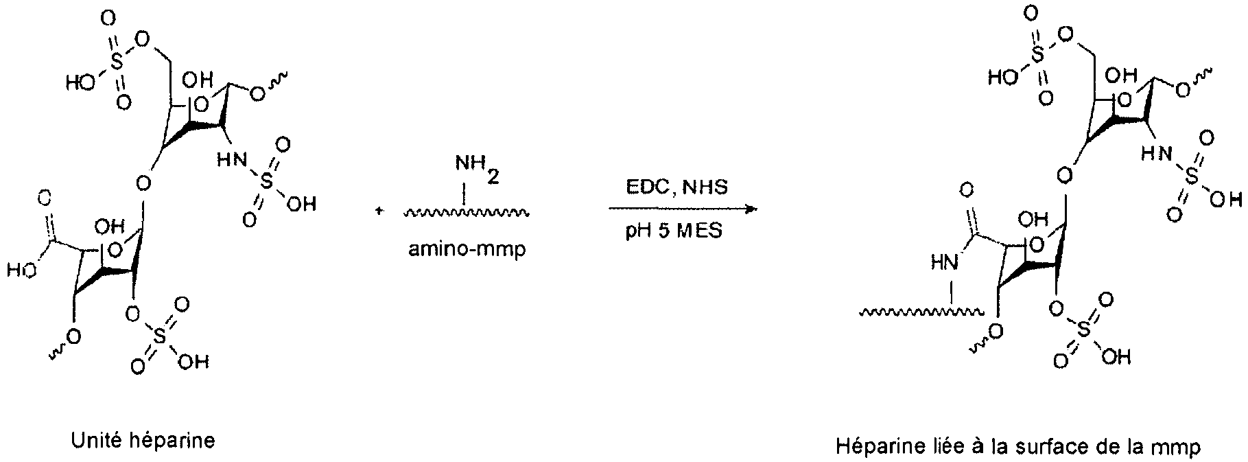
- Procédé selon la revendication 1, comprenant les étapes suivantes :

- Procédé selon la revendication 4 ou 5, dans lequel ladite concentration en EDC/NHS est de 10 mM.
- Procédé selon la revendication 1, dans lequel ladite membrane est associée à une fibre creuse qui entoure un indicateur sensible à un analyte.
- Capteur d'analyte comprenant une membrane à laquelle de l'héparine est fixée par covalence par le procédé de fixation par covalence d'héparine à une membrane, comprenant :le traitement au plasma de la membrane pour produire une membrane à fonctionnalisation amino ; etla réaction de la membrane à fonctionnalisation amino avec de l'héparine dans des conditions dans lesquelles l'héparine se fixe par covalence à la membrane à fonctionnalisation amino, dans lequel ladite héparine est fixée indirectement via un groupe espaceur à ladite membrane à fonctionnalisation amino, dans lequel ladite héparine est fixée à partir d'un site unique dans ladite héparine à un site unique sur ladite membrane à fonctionnalisation amino via ledit groupe espaceur,dans lequel ledit groupe espaceur est du polyéthylène glycol, etdans lequel ladite membrane est une membrane en polyéthylène à haute densité (HDPE).
Applications Claiming Priority (2)
| Application Number | Priority Date | Filing Date | Title |
|---|---|---|---|
| US201161539832P | 2011-09-27 | 2011-09-27 | |
| PCT/US2012/057127 WO2013049068A1 (fr) | 2011-09-27 | 2012-09-25 | Procédé pour fonctionnaliser une couverture de membrane d'un capteur optique pour faciliter le couplage d'un agent antithrombogène |
Publications (3)
| Publication Number | Publication Date |
|---|---|
| EP2760432A1 EP2760432A1 (fr) | 2014-08-06 |
| EP2760432A4 EP2760432A4 (fr) | 2015-09-30 |
| EP2760432B1 true EP2760432B1 (fr) | 2019-03-20 |
Family
ID=47996341
Family Applications (1)
| Application Number | Title | Priority Date | Filing Date |
|---|---|---|---|
| EP12835936.1A Active EP2760432B1 (fr) | 2011-09-27 | 2012-09-25 | Procédé pour fonctionnaliser une couverture de membrane d'un capteur optique pour faciliter le couplage d'un agent antithrombogène |
Country Status (5)
| Country | Link |
|---|---|
| US (1) | US10352941B2 (fr) |
| EP (1) | EP2760432B1 (fr) |
| CA (1) | CA2850148C (fr) |
| DK (1) | DK2760432T3 (fr) |
| WO (1) | WO2013049068A1 (fr) |
Families Citing this family (9)
| Publication number | Priority date | Publication date | Assignee | Title |
|---|---|---|---|---|
| AU2008213677A1 (en) | 2007-02-06 | 2008-08-14 | Glumetrics, Inc. | Optical systems and methods for rationmetric measurement of blood glucose concentration |
| WO2009067626A1 (fr) | 2007-11-21 | 2009-05-28 | Glumetrics, Inc. | Utilisation d'un capteur intravasculaire à l'équilibre pour parvenir à une maîtrise précise de la glycémie |
| GB201416593D0 (en) * | 2014-09-19 | 2014-11-05 | Jozef Stefan Inst And University Of Maribor | Method for immobilization of heparin on a polymeric material |
| EP3095509A1 (fr) * | 2015-05-18 | 2016-11-23 | Defymed | Membranes fonctionnalisées pour organes bioartificiels |
| US9855000B2 (en) | 2015-05-18 | 2018-01-02 | Milo Sensors, Inc. | Transdermal analyte sensing device |
| US9925497B2 (en) * | 2015-07-13 | 2018-03-27 | Hamilton Sunstrand Corporation | Condition monitoring for an air separation module |
| US11673831B2 (en) * | 2019-10-01 | 2023-06-13 | The Hong Kong University Of Science And Technology | Method for preparing optical fibers with high-particle-coated porous polymeric outer coating layers |
| CN111961466B (zh) * | 2020-07-27 | 2022-05-13 | 太原理工大学 | 一种用于检测肝素的碳量子点荧光探针 |
| CN117138131B (zh) * | 2023-10-31 | 2024-03-15 | 北京航天长峰股份有限公司 | 一种抗凝血涂层及其制备方法和应用 |
Family Cites Families (105)
| Publication number | Priority date | Publication date | Assignee | Title |
|---|---|---|---|---|
| US5338157B1 (en) | 1992-09-09 | 1999-11-02 | Sims Deltec Inc | Systems and methods for communicating with ambulat |
| US3846353A (en) | 1970-06-08 | 1974-11-05 | Department Of Health Education | Nonthrombogenic plastic material and method for making the same |
| US4588708A (en) | 1985-04-15 | 1986-05-13 | Kansas State University Research Foundation | Bimetallic solvated metal atom dispersed catalysts |
| US4755173A (en) | 1986-02-25 | 1988-07-05 | Pacesetter Infusion, Ltd. | Soft cannula subcutaneous injection set |
| US5047020A (en) | 1987-09-14 | 1991-09-10 | Baxter International Inc. | Ionic heparin coating |
| US5338770A (en) * | 1988-06-08 | 1994-08-16 | Cardiopulmonics, Inc. | Gas permeable thrombo-resistant coatings and methods of manufacture |
| US5512246A (en) | 1989-09-21 | 1996-04-30 | Anthony P. Russell | Method and means for detecting polyhydroxyl compounds |
| US5137033A (en) | 1991-07-15 | 1992-08-11 | Norton John L | Patient monitoring device |
| US5441759A (en) | 1992-09-03 | 1995-08-15 | Sherwood Medical Company | Method to stabilize TDMAC heparin coating |
| US5956501A (en) | 1997-01-10 | 1999-09-21 | Health Hero Network, Inc. | Disease simulation system and method |
| US5832448A (en) | 1996-10-16 | 1998-11-03 | Health Hero Network | Multiple patient monitoring system for proactive health management |
| US5307263A (en) | 1992-11-17 | 1994-04-26 | Raya Systems, Inc. | Modular microprocessor-based health monitoring system |
| US5545143A (en) | 1993-01-21 | 1996-08-13 | T. S. I. Medical | Device for subcutaneous medication delivery |
| DK25793A (da) | 1993-03-09 | 1994-09-10 | Pharma Plast Int As | Infusionssæt til intermitterende eller kontinuerlig indgivelse af et terapeutisk middel |
| KR0180315B1 (ko) | 1993-06-30 | 1999-03-20 | 알렌 제이. 스피겔 | 환자혈액중의 다수 변수들의 생체내 측정을 위한 다-변수 카테터 |
| GB2284809B (en) | 1993-11-07 | 1998-04-29 | Japan Res Dev Corp | A fluorescent phenylboronic acid suitable for use in the detection of saccharides |
| US5536249A (en) | 1994-03-09 | 1996-07-16 | Visionary Medical Products, Inc. | Pen-type injector with a microprocessor and blood characteristic monitor |
| US5391250A (en) | 1994-03-15 | 1995-02-21 | Minimed Inc. | Method of fabricating thin film sensors |
| US5650234A (en) * | 1994-09-09 | 1997-07-22 | Surface Engineering Technologies, Division Of Innerdyne, Inc. | Electrophilic polyethylene oxides for the modification of polysaccharides, polypeptides (proteins) and surfaces |
| US5643580A (en) * | 1994-10-17 | 1997-07-01 | Surface Genesis, Inc. | Biocompatible coating, medical device using the same and methods |
| IE72524B1 (en) | 1994-11-04 | 1997-04-23 | Elan Med Tech | Analyte-controlled liquid delivery device and analyte monitor |
| US5665065A (en) | 1995-05-26 | 1997-09-09 | Minimed Inc. | Medication infusion device with blood glucose data input |
| EP0862648B1 (fr) | 1995-11-22 | 2004-10-06 | Medtronic MiniMed, Inc. | Detection de molecules biologiques par amplification chimique et au moyen de detecteurs optiques |
| US6766183B2 (en) | 1995-11-22 | 2004-07-20 | Medtronic Minimed, Inc. | Long wave fluorophore sensor compounds and other fluorescent sensor compounds in polymers |
| US6607509B2 (en) | 1997-12-31 | 2003-08-19 | Medtronic Minimed, Inc. | Insertion device for an insertion set and method of using the same |
| DE19717107B4 (de) | 1997-04-23 | 2005-06-23 | Disetronic Licensing Ag | System aus Behältnis und Antriebsvorrichtung für einen Kolben, der in dem ein Medikamentfluid enthaltenden Behältnis gehalten ist |
| US6186982B1 (en) | 1998-05-05 | 2001-02-13 | Elan Corporation, Plc | Subcutaneous drug delivery device with improved filling system |
| US6558351B1 (en) | 1999-06-03 | 2003-05-06 | Medtronic Minimed, Inc. | Closed loop system for controlling insulin infusion |
| US5954643A (en) | 1997-06-09 | 1999-09-21 | Minimid Inc. | Insertion set for a transcutaneous sensor |
| US7647237B2 (en) | 1998-04-29 | 2010-01-12 | Minimed, Inc. | Communication station and software for interfacing with an infusion pump, analyte monitor, analyte meter, or the like |
| US6175752B1 (en) | 1998-04-30 | 2001-01-16 | Therasense, Inc. | Analyte monitoring device and methods of use |
| US6736797B1 (en) | 1998-06-19 | 2004-05-18 | Unomedical A/S | Subcutaneous infusion set |
| US6355021B1 (en) | 1998-07-14 | 2002-03-12 | Maersk Medical A/S | Medical puncturing device |
| US6558320B1 (en) | 2000-01-20 | 2003-05-06 | Medtronic Minimed, Inc. | Handheld personal data assistant (PDA) with a medical device and method of using the same |
| US6248067B1 (en) | 1999-02-05 | 2001-06-19 | Minimed Inc. | Analyte sensor and holter-type monitor system and method of using the same |
| US6554798B1 (en) | 1998-08-18 | 2003-04-29 | Medtronic Minimed, Inc. | External infusion device with remote programming, bolus estimator and/or vibration alarm capabilities |
| JP4469504B2 (ja) | 1998-10-08 | 2010-05-26 | メドトロニック ミニメド インコーポレイテッド | 遠隔形質モニタシステム |
| DE69928827T2 (de) | 1998-10-29 | 2006-08-31 | Medtronic MiniMed, Inc., Northridge | Reservoiranschluss |
| US6248093B1 (en) | 1998-10-29 | 2001-06-19 | Minimed Inc. | Compact pump drive system |
| US7193521B2 (en) | 1998-10-29 | 2007-03-20 | Medtronic Minimed, Inc. | Method and apparatus for detecting errors, fluid pressure, and occlusions in an ambulatory infusion pump |
| US7806886B2 (en) | 1999-06-03 | 2010-10-05 | Medtronic Minimed, Inc. | Apparatus and method for controlling insulin infusion with state variable feedback |
| US6453956B2 (en) | 1999-11-05 | 2002-09-24 | Medtronic Minimed, Inc. | Needle safe transfer guard |
| US7003336B2 (en) | 2000-02-10 | 2006-02-21 | Medtronic Minimed, Inc. | Analyte sensor method of making the same |
| US6895263B2 (en) | 2000-02-23 | 2005-05-17 | Medtronic Minimed, Inc. | Real time self-adjusting calibration algorithm |
| US7890295B2 (en) | 2000-02-23 | 2011-02-15 | Medtronic Minimed, Inc. | Real time self-adjusting calibration algorithm |
| US20010041869A1 (en) | 2000-03-23 | 2001-11-15 | Causey James D. | Control tabs for infusion devices and methods of using the same |
| CA2771723C (fr) | 2000-09-08 | 2016-03-29 | Insulet Corporation | Dispositifs, systemes et procedes de perfusion d'un patient |
| US7470420B2 (en) | 2000-12-05 | 2008-12-30 | The Regents Of The University Of California | Optical determination of glucose utilizing boronic acid adducts |
| US6627177B2 (en) | 2000-12-05 | 2003-09-30 | The Regents Of The University Of California | Polyhydroxyl-substituted organic molecule sensing optical in vivo method utilizing a boronic acid adduct and the device thereof |
| JP2004532670A (ja) | 2001-02-22 | 2004-10-28 | インシュレット コーポレイション | モジュール式の輸液装置及び方法 |
| DK3210637T3 (da) | 2001-04-06 | 2021-04-06 | Hoffmann La Roche | Infusionssæt |
| US20020071225A1 (en) | 2001-04-19 | 2002-06-13 | Minimed Inc. | Direct current motor safety circuits for fluid delivery systems |
| US6544212B2 (en) | 2001-07-31 | 2003-04-08 | Roche Diagnostics Corporation | Diabetes management system |
| US7399277B2 (en) | 2001-12-27 | 2008-07-15 | Medtronic Minimed, Inc. | System for monitoring physiological characteristics |
| US8010174B2 (en) | 2003-08-22 | 2011-08-30 | Dexcom, Inc. | Systems and methods for replacing signal artifacts in a glucose sensor data stream |
| WO2003072155A1 (fr) | 2002-02-21 | 2003-09-04 | Encelle, Inc. | Matrices d'hydrogel bioactif reticule |
| US7041082B2 (en) | 2002-02-28 | 2006-05-09 | Smiths Medical Md, Inc. | Syringe pump control systems and methods |
| US6960192B1 (en) | 2002-04-23 | 2005-11-01 | Insulet Corporation | Transcutaneous fluid delivery system |
| US20040068230A1 (en) | 2002-07-24 | 2004-04-08 | Medtronic Minimed, Inc. | System for providing blood glucose measurements to an infusion device |
| US7278983B2 (en) | 2002-07-24 | 2007-10-09 | Medtronic Minimed, Inc. | Physiological monitoring device for controlling a medication infusion device |
| US7488601B2 (en) | 2003-06-20 | 2009-02-10 | Roche Diagnostic Operations, Inc. | System and method for determining an abused sensor during analyte measurement |
| US8275437B2 (en) | 2003-08-01 | 2012-09-25 | Dexcom, Inc. | Transcutaneous analyte sensor |
| US7699807B2 (en) | 2003-11-10 | 2010-04-20 | Smiths Medical Asd, Inc. | Device and method for insertion of a cannula of an infusion device |
| EP2316331B1 (fr) | 2003-12-09 | 2016-06-29 | Dexcom, Inc. | Traitement de signal pour capteur d'analyte continu |
| GB0329161D0 (en) | 2003-12-16 | 2004-01-21 | Precisense As | Reagant for detecting an analyte |
| GB0329849D0 (en) | 2003-12-23 | 2004-01-28 | Precisense As | Fluorometers |
| US9561309B2 (en) * | 2004-05-27 | 2017-02-07 | Advanced Cardiovascular Systems, Inc. | Antifouling heparin coatings |
| US7344500B2 (en) | 2004-07-27 | 2008-03-18 | Medtronic Minimed, Inc. | Sensing system with auxiliary display |
| US8313433B2 (en) | 2004-08-06 | 2012-11-20 | Medtronic Minimed, Inc. | Medical data management system and process |
| US20060039950A1 (en) * | 2004-08-23 | 2006-02-23 | Zhengrong Zhou | Multi-functional biocompatible coatings for intravascular devices |
| US7468033B2 (en) | 2004-09-08 | 2008-12-23 | Medtronic Minimed, Inc. | Blood contacting sensor |
| CN101180093B (zh) | 2005-03-21 | 2012-07-18 | 雅培糖尿病护理公司 | 用于提供结合的药剂输液以及分析物监测系统的方法和系统 |
| US8298172B2 (en) | 2005-04-13 | 2012-10-30 | Novo Nordisk A/S | Medical skin mountable device and system |
| US20080097291A1 (en) | 2006-08-23 | 2008-04-24 | Hanson Ian B | Infusion pumps and methods and delivery devices and methods with same |
| US8137314B2 (en) | 2006-08-23 | 2012-03-20 | Medtronic Minimed, Inc. | Infusion medium delivery device and method with compressible or curved reservoir or conduit |
| US7569050B2 (en) | 2005-05-06 | 2009-08-04 | Medtronic Minimed, Inc. | Infusion device and method with drive device in infusion device and method with drive device in separable durable housing portion |
| US8277415B2 (en) | 2006-08-23 | 2012-10-02 | Medtronic Minimed, Inc. | Infusion medium delivery device and method with drive device for driving plunger in reservoir |
| US7713240B2 (en) | 2005-09-13 | 2010-05-11 | Medtronic Minimed, Inc. | Modular external infusion device |
| DE602006008494D1 (de) | 2005-11-08 | 2009-09-24 | M2 Medical As | Infusionspumpensystem |
| US8114268B2 (en) | 2005-12-30 | 2012-02-14 | Medtronic Minimed, Inc. | Method and system for remedying sensor malfunctions detected by electrochemical impedance spectroscopy |
| US7985330B2 (en) | 2005-12-30 | 2011-07-26 | Medtronic Minimed, Inc. | Method and system for detecting age, hydration, and functional states of sensors using electrochemical impedance spectroscopy |
| US8114269B2 (en) | 2005-12-30 | 2012-02-14 | Medtronic Minimed, Inc. | System and method for determining the point of hydration and proper time to apply potential to a glucose sensor |
| US20070255125A1 (en) | 2006-04-28 | 2007-11-01 | Moberg Sheldon B | Monitor devices for networked fluid infusion systems |
| ATE514755T1 (de) | 2006-07-25 | 2011-07-15 | Glumetrics Inc | Fluoreszenzfarbstoffe zur verwendung bei der glukoseerfassung |
| US7828764B2 (en) | 2006-08-23 | 2010-11-09 | Medtronic Minimed, Inc. | Systems and methods allowing for reservoir filling and infusion medium delivery |
| US7682338B2 (en) | 2006-08-23 | 2010-03-23 | Medtronic Minimed, Inc. | Infusion medium delivery system, device and method with needle inserter and needle inserter device and method |
| US20080125700A1 (en) | 2006-11-29 | 2008-05-29 | Moberg Sheldon B | Methods and apparatuses for detecting medical device acceleration, temperature, and humidity conditions |
| US7946985B2 (en) | 2006-12-29 | 2011-05-24 | Medtronic Minimed, Inc. | Method and system for providing sensor redundancy |
| AU2008213677A1 (en) | 2007-02-06 | 2008-08-14 | Glumetrics, Inc. | Optical systems and methods for rationmetric measurement of blood glucose concentration |
| US7751863B2 (en) | 2007-02-06 | 2010-07-06 | Glumetrics, Inc. | Optical determination of ph and glucose |
| EP2122334B1 (fr) | 2007-02-06 | 2018-01-24 | Medtronic Minimed, Inc. | Procédé de polymérisation d'une solution de monomère dans une cavité pour générer une surface de polymère lisse |
| US20080269714A1 (en) | 2007-04-25 | 2008-10-30 | Medtronic Minimed, Inc. | Closed loop/semi-closed loop therapy modification system |
| US8323250B2 (en) | 2007-04-30 | 2012-12-04 | Medtronic Minimed, Inc. | Adhesive patch systems and methods |
| US7963954B2 (en) | 2007-04-30 | 2011-06-21 | Medtronic Minimed, Inc. | Automated filling systems and methods |
| JP5706686B2 (ja) | 2007-05-01 | 2015-04-22 | メドトロニック ミニメド インコーポレイテッド | ピリジニウムボロン酸消光体、その製造方法、およびグルコースセンサー |
| JP5517919B2 (ja) | 2007-05-10 | 2014-06-11 | グルメトリクス、 インク. | 即時血管内グルコース測定のための平衡非消費蛍光センサー |
| EP2150814A2 (fr) | 2007-05-10 | 2010-02-10 | Glumetrics, Inc. | Dispositif et procédés de calibrage de détecteurs d'analytes |
| JP2010534085A (ja) | 2007-07-20 | 2010-11-04 | メディンゴ・リミテッド | 手動操作可能な携帯式注入装置 |
| EP2055369A1 (fr) * | 2007-10-30 | 2009-05-06 | Sensile Pat AG | Membrane revêtue perméable sensiblement |
| US7888754B2 (en) * | 2007-12-28 | 2011-02-15 | Yamaha Corporation | MEMS transducer |
| US8207859B2 (en) | 2008-04-28 | 2012-06-26 | Medtronic Minimed, Inc. | Automobile physiological monitoring system and method for using the same |
| US8181849B2 (en) | 2008-12-30 | 2012-05-22 | Medtronic Minimed, Inc. | Color detection system for detecting reservoir presence and content in device |
| US8308679B2 (en) | 2009-12-30 | 2012-11-13 | Medtronic Minimed, Inc. | Alignment systems and methods |
| EP2483679A4 (fr) * | 2009-09-30 | 2013-04-24 | Glumetrics Inc | Capteurs dotés de revêtements thromborésistants |
| EP2412798A1 (fr) * | 2010-07-27 | 2012-02-01 | Gambro Lundia AB | Membrane biomimétique pour cultiver des cellules |
-
2012
- 2012-09-25 EP EP12835936.1A patent/EP2760432B1/fr active Active
- 2012-09-25 WO PCT/US2012/057127 patent/WO2013049068A1/fr not_active Ceased
- 2012-09-25 DK DK12835936.1T patent/DK2760432T3/da active
- 2012-09-25 US US14/347,567 patent/US10352941B2/en active Active
- 2012-09-25 CA CA2850148A patent/CA2850148C/fr active Active
Non-Patent Citations (1)
| Title |
|---|
| XIN QU ET AL: "Surface modification of high density polyethylene tubes by coating chitosan, chitosan hydrogel and heparin", POLYMER BULLETIN., vol. 46, no. 2-3, 1 April 2001 (2001-04-01), DE, pages 223 - 229, XP055295643, ISSN: 0170-0839, DOI: 10.1007/s002890170078 * |
Also Published As
| Publication number | Publication date |
|---|---|
| WO2013049068A8 (fr) | 2013-06-20 |
| US10352941B2 (en) | 2019-07-16 |
| EP2760432A1 (fr) | 2014-08-06 |
| DK2760432T3 (da) | 2019-06-11 |
| CA2850148A1 (fr) | 2013-04-04 |
| US20140242710A1 (en) | 2014-08-28 |
| EP2760432A4 (fr) | 2015-09-30 |
| WO2013049068A1 (fr) | 2013-04-04 |
| CA2850148C (fr) | 2020-02-25 |
Similar Documents
| Publication | Publication Date | Title |
|---|---|---|
| US8715589B2 (en) | Sensors with thromboresistant coating | |
| US10352941B2 (en) | Method for functionalizing a porous membrane covering of an optical sensor to facilitate coupling of an antithrom-bogenic agent | |
| US8377461B2 (en) | Multifunctional medical articles | |
| US8632877B2 (en) | Ultra-thin photo-polymer coatings and uses thereof | |
| US20120053427A1 (en) | Optical sensor configuration and methods for monitoring glucose activity in interstitial fluid | |
| US6303179B1 (en) | Method for attachment of biomolecules to surfaces through amine-functional groups | |
| CA2732939C (fr) | Entites biologiques immobilisees | |
| ES2668220T3 (es) | Nuevas entidades de heparina y métodos de uso | |
| AU704572B2 (en) | Biocompatible coating, medical device using the same and methods | |
| JP2020108864A (ja) | 固定された生物学的実体 | |
| Sharma et al. | Nanostructured antifouling poly (ethylene glycol) films for silicon-based microsystems |
Legal Events
| Date | Code | Title | Description |
|---|---|---|---|
| PUAI | Public reference made under article 153(3) epc to a published international application that has entered the european phase |
Free format text: ORIGINAL CODE: 0009012 |
|
| 17P | Request for examination filed |
Effective date: 20140407 |
|
| AK | Designated contracting states |
Kind code of ref document: A1 Designated state(s): AL AT BE BG CH CY CZ DE DK EE ES FI FR GB GR HR HU IE IS IT LI LT LU LV MC MK MT NL NO PL PT RO RS SE SI SK SM TR |
|
| DAX | Request for extension of the european patent (deleted) | ||
| RIC1 | Information provided on ipc code assigned before grant |
Ipc: A61K 9/00 20060101AFI20150526BHEP Ipc: A61L 33/00 20060101ALI20150526BHEP Ipc: G01N 33/543 20060101ALI20150526BHEP Ipc: B05D 3/00 20060101ALI20150526BHEP |
|
| RAP1 | Party data changed (applicant data changed or rights of an application transferred) |
Owner name: MEDTRONIC MINIMED, INC. |
|
| RA4 | Supplementary search report drawn up and despatched (corrected) |
Effective date: 20150828 |
|
| RIC1 | Information provided on ipc code assigned before grant |
Ipc: A61K 9/00 20060101AFI20150824BHEP Ipc: B05D 3/00 20060101ALI20150824BHEP Ipc: G01N 33/543 20060101ALI20150824BHEP Ipc: A61L 33/00 20060101ALI20150824BHEP |
|
| STAA | Information on the status of an ep patent application or granted ep patent |
Free format text: STATUS: EXAMINATION IS IN PROGRESS |
|
| 17Q | First examination report despatched |
Effective date: 20161111 |
|
| GRAP | Despatch of communication of intention to grant a patent |
Free format text: ORIGINAL CODE: EPIDOSNIGR1 |
|
| STAA | Information on the status of an ep patent application or granted ep patent |
Free format text: STATUS: GRANT OF PATENT IS INTENDED |
|
| INTG | Intention to grant announced |
Effective date: 20181026 |
|
| GRAS | Grant fee paid |
Free format text: ORIGINAL CODE: EPIDOSNIGR3 |
|
| GRAA | (expected) grant |
Free format text: ORIGINAL CODE: 0009210 |
|
| STAA | Information on the status of an ep patent application or granted ep patent |
Free format text: STATUS: THE PATENT HAS BEEN GRANTED |
|
| AK | Designated contracting states |
Kind code of ref document: B1 Designated state(s): AL AT BE BG CH CY CZ DE DK EE ES FI FR GB GR HR HU IE IS IT LI LT LU LV MC MK MT NL NO PL PT RO RS SE SI SK SM TR |
|
| REG | Reference to a national code |
Ref country code: GB Ref legal event code: FG4D |
|
| REG | Reference to a national code |
Ref country code: CH Ref legal event code: EP |
|
| REG | Reference to a national code |
Ref country code: DE Ref legal event code: R096 Ref document number: 602012058116 Country of ref document: DE |
|
| REG | Reference to a national code |
Ref country code: AT Ref legal event code: REF Ref document number: 1109772 Country of ref document: AT Kind code of ref document: T Effective date: 20190415 |
|
| REG | Reference to a national code |
Ref country code: IE Ref legal event code: FG4D |
|
| REG | Reference to a national code |
Ref country code: DK Ref legal event code: T3 Effective date: 20190607 |
|
| REG | Reference to a national code |
Ref country code: NL Ref legal event code: MP Effective date: 20190320 |
|
| PG25 | Lapsed in a contracting state [announced via postgrant information from national office to epo] |
Ref country code: NO Free format text: LAPSE BECAUSE OF FAILURE TO SUBMIT A TRANSLATION OF THE DESCRIPTION OR TO PAY THE FEE WITHIN THE PRESCRIBED TIME-LIMIT Effective date: 20190620 Ref country code: FI Free format text: LAPSE BECAUSE OF FAILURE TO SUBMIT A TRANSLATION OF THE DESCRIPTION OR TO PAY THE FEE WITHIN THE PRESCRIBED TIME-LIMIT Effective date: 20190320 Ref country code: SE Free format text: LAPSE BECAUSE OF FAILURE TO SUBMIT A TRANSLATION OF THE DESCRIPTION OR TO PAY THE FEE WITHIN THE PRESCRIBED TIME-LIMIT Effective date: 20190320 Ref country code: LT Free format text: LAPSE BECAUSE OF FAILURE TO SUBMIT A TRANSLATION OF THE DESCRIPTION OR TO PAY THE FEE WITHIN THE PRESCRIBED TIME-LIMIT Effective date: 20190320 |
|
| REG | Reference to a national code |
Ref country code: LT Ref legal event code: MG4D |
|
| PG25 | Lapsed in a contracting state [announced via postgrant information from national office to epo] |
Ref country code: LV Free format text: LAPSE BECAUSE OF FAILURE TO SUBMIT A TRANSLATION OF THE DESCRIPTION OR TO PAY THE FEE WITHIN THE PRESCRIBED TIME-LIMIT Effective date: 20190320 Ref country code: HR Free format text: LAPSE BECAUSE OF FAILURE TO SUBMIT A TRANSLATION OF THE DESCRIPTION OR TO PAY THE FEE WITHIN THE PRESCRIBED TIME-LIMIT Effective date: 20190320 Ref country code: NL Free format text: LAPSE BECAUSE OF FAILURE TO SUBMIT A TRANSLATION OF THE DESCRIPTION OR TO PAY THE FEE WITHIN THE PRESCRIBED TIME-LIMIT Effective date: 20190320 Ref country code: BG Free format text: LAPSE BECAUSE OF FAILURE TO SUBMIT A TRANSLATION OF THE DESCRIPTION OR TO PAY THE FEE WITHIN THE PRESCRIBED TIME-LIMIT Effective date: 20190620 Ref country code: GR Free format text: LAPSE BECAUSE OF FAILURE TO SUBMIT A TRANSLATION OF THE DESCRIPTION OR TO PAY THE FEE WITHIN THE PRESCRIBED TIME-LIMIT Effective date: 20190621 Ref country code: RS Free format text: LAPSE BECAUSE OF FAILURE TO SUBMIT A TRANSLATION OF THE DESCRIPTION OR TO PAY THE FEE WITHIN THE PRESCRIBED TIME-LIMIT Effective date: 20190320 |
|
| REG | Reference to a national code |
Ref country code: AT Ref legal event code: MK05 Ref document number: 1109772 Country of ref document: AT Kind code of ref document: T Effective date: 20190320 |
|
| PG25 | Lapsed in a contracting state [announced via postgrant information from national office to epo] |
Ref country code: ES Free format text: LAPSE BECAUSE OF FAILURE TO SUBMIT A TRANSLATION OF THE DESCRIPTION OR TO PAY THE FEE WITHIN THE PRESCRIBED TIME-LIMIT Effective date: 20190320 Ref country code: PT Free format text: LAPSE BECAUSE OF FAILURE TO SUBMIT A TRANSLATION OF THE DESCRIPTION OR TO PAY THE FEE WITHIN THE PRESCRIBED TIME-LIMIT Effective date: 20190720 Ref country code: AL Free format text: LAPSE BECAUSE OF FAILURE TO SUBMIT A TRANSLATION OF THE DESCRIPTION OR TO PAY THE FEE WITHIN THE PRESCRIBED TIME-LIMIT Effective date: 20190320 Ref country code: EE Free format text: LAPSE BECAUSE OF FAILURE TO SUBMIT A TRANSLATION OF THE DESCRIPTION OR TO PAY THE FEE WITHIN THE PRESCRIBED TIME-LIMIT Effective date: 20190320 Ref country code: IT Free format text: LAPSE BECAUSE OF FAILURE TO SUBMIT A TRANSLATION OF THE DESCRIPTION OR TO PAY THE FEE WITHIN THE PRESCRIBED TIME-LIMIT Effective date: 20190320 Ref country code: RO Free format text: LAPSE BECAUSE OF FAILURE TO SUBMIT A TRANSLATION OF THE DESCRIPTION OR TO PAY THE FEE WITHIN THE PRESCRIBED TIME-LIMIT Effective date: 20190320 Ref country code: SK Free format text: LAPSE BECAUSE OF FAILURE TO SUBMIT A TRANSLATION OF THE DESCRIPTION OR TO PAY THE FEE WITHIN THE PRESCRIBED TIME-LIMIT Effective date: 20190320 Ref country code: CZ Free format text: LAPSE BECAUSE OF FAILURE TO SUBMIT A TRANSLATION OF THE DESCRIPTION OR TO PAY THE FEE WITHIN THE PRESCRIBED TIME-LIMIT Effective date: 20190320 |
|
| PG25 | Lapsed in a contracting state [announced via postgrant information from national office to epo] |
Ref country code: PL Free format text: LAPSE BECAUSE OF FAILURE TO SUBMIT A TRANSLATION OF THE DESCRIPTION OR TO PAY THE FEE WITHIN THE PRESCRIBED TIME-LIMIT Effective date: 20190320 Ref country code: SM Free format text: LAPSE BECAUSE OF FAILURE TO SUBMIT A TRANSLATION OF THE DESCRIPTION OR TO PAY THE FEE WITHIN THE PRESCRIBED TIME-LIMIT Effective date: 20190320 |
|
| PG25 | Lapsed in a contracting state [announced via postgrant information from national office to epo] |
Ref country code: AT Free format text: LAPSE BECAUSE OF FAILURE TO SUBMIT A TRANSLATION OF THE DESCRIPTION OR TO PAY THE FEE WITHIN THE PRESCRIBED TIME-LIMIT Effective date: 20190320 Ref country code: IS Free format text: LAPSE BECAUSE OF FAILURE TO SUBMIT A TRANSLATION OF THE DESCRIPTION OR TO PAY THE FEE WITHIN THE PRESCRIBED TIME-LIMIT Effective date: 20190720 |
|
| REG | Reference to a national code |
Ref country code: DE Ref legal event code: R097 Ref document number: 602012058116 Country of ref document: DE |
|
| PLBE | No opposition filed within time limit |
Free format text: ORIGINAL CODE: 0009261 |
|
| STAA | Information on the status of an ep patent application or granted ep patent |
Free format text: STATUS: NO OPPOSITION FILED WITHIN TIME LIMIT |
|
| 26N | No opposition filed |
Effective date: 20200102 |
|
| PG25 | Lapsed in a contracting state [announced via postgrant information from national office to epo] |
Ref country code: SI Free format text: LAPSE BECAUSE OF FAILURE TO SUBMIT A TRANSLATION OF THE DESCRIPTION OR TO PAY THE FEE WITHIN THE PRESCRIBED TIME-LIMIT Effective date: 20190320 |
|
| PG25 | Lapsed in a contracting state [announced via postgrant information from national office to epo] |
Ref country code: TR Free format text: LAPSE BECAUSE OF FAILURE TO SUBMIT A TRANSLATION OF THE DESCRIPTION OR TO PAY THE FEE WITHIN THE PRESCRIBED TIME-LIMIT Effective date: 20190320 |
|
| PG25 | Lapsed in a contracting state [announced via postgrant information from national office to epo] |
Ref country code: MC Free format text: LAPSE BECAUSE OF FAILURE TO SUBMIT A TRANSLATION OF THE DESCRIPTION OR TO PAY THE FEE WITHIN THE PRESCRIBED TIME-LIMIT Effective date: 20190320 |
|
| REG | Reference to a national code |
Ref country code: CH Ref legal event code: PL |
|
| PG25 | Lapsed in a contracting state [announced via postgrant information from national office to epo] |
Ref country code: IE Free format text: LAPSE BECAUSE OF NON-PAYMENT OF DUE FEES Effective date: 20190925 Ref country code: LU Free format text: LAPSE BECAUSE OF NON-PAYMENT OF DUE FEES Effective date: 20190925 Ref country code: LI Free format text: LAPSE BECAUSE OF NON-PAYMENT OF DUE FEES Effective date: 20190930 Ref country code: CH Free format text: LAPSE BECAUSE OF NON-PAYMENT OF DUE FEES Effective date: 20190930 |
|
| REG | Reference to a national code |
Ref country code: BE Ref legal event code: MM Effective date: 20190930 |
|
| PG25 | Lapsed in a contracting state [announced via postgrant information from national office to epo] |
Ref country code: BE Free format text: LAPSE BECAUSE OF NON-PAYMENT OF DUE FEES Effective date: 20190930 |
|
| PGFP | Annual fee paid to national office [announced via postgrant information from national office to epo] |
Ref country code: GB Payment date: 20200819 Year of fee payment: 9 |
|
| PG25 | Lapsed in a contracting state [announced via postgrant information from national office to epo] |
Ref country code: CY Free format text: LAPSE BECAUSE OF FAILURE TO SUBMIT A TRANSLATION OF THE DESCRIPTION OR TO PAY THE FEE WITHIN THE PRESCRIBED TIME-LIMIT Effective date: 20190320 |
|
| PG25 | Lapsed in a contracting state [announced via postgrant information from national office to epo] |
Ref country code: MT Free format text: LAPSE BECAUSE OF FAILURE TO SUBMIT A TRANSLATION OF THE DESCRIPTION OR TO PAY THE FEE WITHIN THE PRESCRIBED TIME-LIMIT Effective date: 20190320 Ref country code: HU Free format text: LAPSE BECAUSE OF FAILURE TO SUBMIT A TRANSLATION OF THE DESCRIPTION OR TO PAY THE FEE WITHIN THE PRESCRIBED TIME-LIMIT; INVALID AB INITIO Effective date: 20120925 |
|
| GBPC | Gb: european patent ceased through non-payment of renewal fee |
Effective date: 20210925 |
|
| PG25 | Lapsed in a contracting state [announced via postgrant information from national office to epo] |
Ref country code: MK Free format text: LAPSE BECAUSE OF FAILURE TO SUBMIT A TRANSLATION OF THE DESCRIPTION OR TO PAY THE FEE WITHIN THE PRESCRIBED TIME-LIMIT Effective date: 20190320 |
|
| PG25 | Lapsed in a contracting state [announced via postgrant information from national office to epo] |
Ref country code: GB Free format text: LAPSE BECAUSE OF NON-PAYMENT OF DUE FEES Effective date: 20210925 |
|
| REG | Reference to a national code |
Ref country code: DE Ref legal event code: R082 Ref document number: 602012058116 Country of ref document: DE Representative=s name: MEISSNER BOLTE PATENTANWAELTE RECHTSANWAELTE P, DE |
|
| PGFP | Annual fee paid to national office [announced via postgrant information from national office to epo] |
Ref country code: DK Payment date: 20250820 Year of fee payment: 14 Ref country code: DE Payment date: 20250820 Year of fee payment: 14 |
|
| PGFP | Annual fee paid to national office [announced via postgrant information from national office to epo] |
Ref country code: FR Payment date: 20250820 Year of fee payment: 14 |