EP2761232B1 - Wärmeaustauschsystem zur konditionierung von rauminnenluft - Google Patents
Wärmeaustauschsystem zur konditionierung von rauminnenluft Download PDFInfo
- Publication number
- EP2761232B1 EP2761232B1 EP12775765.6A EP12775765A EP2761232B1 EP 2761232 B1 EP2761232 B1 EP 2761232B1 EP 12775765 A EP12775765 A EP 12775765A EP 2761232 B1 EP2761232 B1 EP 2761232B1
- Authority
- EP
- European Patent Office
- Prior art keywords
- heat exchanger
- exchange system
- heat exchange
- heat
- chamber
- Prior art date
- Legal status (The legal status is an assumption and is not a legal conclusion. Google has not performed a legal analysis and makes no representation as to the accuracy of the status listed.)
- Not-in-force
Links
- 230000003750 conditioning effect Effects 0.000 title description 4
- 239000013529 heat transfer fluid Substances 0.000 claims description 8
- 238000007664 blowing Methods 0.000 claims description 5
- 238000009434 installation Methods 0.000 claims description 2
- 238000004378 air conditioning Methods 0.000 claims 1
- 230000000284 resting effect Effects 0.000 claims 1
- 235000021183 entrée Nutrition 0.000 description 12
- 230000006835 compression Effects 0.000 description 11
- 238000007906 compression Methods 0.000 description 11
- 239000002826 coolant Substances 0.000 description 9
- 238000005192 partition Methods 0.000 description 4
- 238000010438 heat treatment Methods 0.000 description 2
- 239000002689 soil Substances 0.000 description 2
- 238000013517 stratification Methods 0.000 description 2
- 241001080024 Telles Species 0.000 description 1
- 238000001816 cooling Methods 0.000 description 1
- 230000000694 effects Effects 0.000 description 1
- 239000012530 fluid Substances 0.000 description 1
- 239000003507 refrigerant Substances 0.000 description 1
- 238000009418 renovation Methods 0.000 description 1
- XLYOFNOQVPJJNP-UHFFFAOYSA-N water Substances O XLYOFNOQVPJJNP-UHFFFAOYSA-N 0.000 description 1
Images


Classifications
-
- F—MECHANICAL ENGINEERING; LIGHTING; HEATING; WEAPONS; BLASTING
- F24—HEATING; RANGES; VENTILATING
- F24F—AIR-CONDITIONING; AIR-HUMIDIFICATION; VENTILATION; USE OF AIR CURRENTS FOR SCREENING
- F24F1/00—Room units for air-conditioning, e.g. separate or self-contained units or units receiving primary air from a central station
- F24F1/02—Self-contained room units for air-conditioning, i.e. with all apparatus for treatment installed in a common casing
- F24F1/022—Self-contained room units for air-conditioning, i.e. with all apparatus for treatment installed in a common casing comprising a compressor cycle
-
- F—MECHANICAL ENGINEERING; LIGHTING; HEATING; WEAPONS; BLASTING
- F24—HEATING; RANGES; VENTILATING
- F24F—AIR-CONDITIONING; AIR-HUMIDIFICATION; VENTILATION; USE OF AIR CURRENTS FOR SCREENING
- F24F13/00—Details common to, or for air-conditioning, air-humidification, ventilation or use of air currents for screening
- F24F13/08—Air-flow control members, e.g. louvres, grilles, flaps or guide plates
- F24F13/082—Grilles, registers or guards
-
- F—MECHANICAL ENGINEERING; LIGHTING; HEATING; WEAPONS; BLASTING
- F24—HEATING; RANGES; VENTILATING
- F24F—AIR-CONDITIONING; AIR-HUMIDIFICATION; VENTILATION; USE OF AIR CURRENTS FOR SCREENING
- F24F13/00—Details common to, or for air-conditioning, air-humidification, ventilation or use of air currents for screening
- F24F13/22—Means for preventing condensation or evacuating condensate
- F24F13/222—Means for preventing condensation or evacuating condensate for evacuating condensate
Definitions
- the invention relates to a heat exchange system for conditioning the interior air of a space.
- the invention relates, in particular, to a heat exchange system which allows, in a heat pump mode, to take heat from an external environment situated outside the space to transfer it to the interior air located inside the space, and thus heat the space, or, in an air conditioner mode, to take heat from the indoor air to transfer it to the outside environment, and thus to cool the space.
- a heat exchange system uses two heat exchangers in which circulates a coolant and alternately forming an evaporator, adapted to collect heat, and a condenser, adapted to transfer the heat.
- the invention finds application in the context of the renovation of heating system, for example electric Joule effect.
- the heat exchange system may then comprise an enclosure having a base near which one of the heat exchangers is disposed.
- the heat exchanger can then advantageously be arranged obliquely facing an air inlet opening formed in the base and partially closed by a grid.
- the document US 4,733,542 describes a heat exchange system of the aforementioned type.
- the document US 5,918,666 describes, moreover, a heat exchange system according to the preamble of claim 1.
- the known heat exchange system does not provide optimum efficiency.
- the heat exchange system poses problems of pressure drop at the air inlet.
- the heat exchange system does not provide a satisfactory drainage of condensates which, in air conditioner mode, form on the evaporator heat exchanger and can reach up to 0.5 to 0.8 l / h per cold kW.
- the invention aims to overcome the problems mentioned above.
- the base and the grid which have a slope towards the front face of the enclosure make it possible to increase the passage section of the interior air, thus significantly reducing the pressure losses at the air inlet.
- the inclination of the grid makes it possible to increase the section of passage between the fins and thus to limit the one-off pressure losses.
- the inclination of the base and the grid makes it possible to work the first heat exchanger more homogeneously and more efficiently by better distributing the internal air flows that pass through it.
- the conformation of the fins makes it possible to increase the collection area of the condensates, to standardize it at any point of the first heat exchanger and thus to improve the evacuation of the condensates.
- the interior air flow can enter being oriented orthogonally with respect to the first heat exchanger, so as to optimize the thermal efficiency of the heat exchange system.
- the provisions concerning the base and the grid also improve the compactness of the heat exchange system.
- the base and the first heat exchanger can extend generally parallel to each other, the grid extending generally parallel to the first heat exchanger.
- the base and the grid can thus have an inclination identical (within plus or minus 20 °) to that of the first heat exchanger.
- each fin may have a concavity facing the first heat exchanger and the lower surface of each fin may have an outwardly facing convexity.
- the fins may be shaped so that a projection of the upper surfaces on a projection plane perpendicular to the vertical direction completely covers a projection of the air inlet opening on the projection plane.
- Each fin may extend in a longitudinal direction perpendicular to the vertical direction, the fins being spaced from each other in a transverse direction perpendicular to the longitudinal and vertical directions, and spaced from each other in the vertical direction.
- Each fin may then have a generally V-shaped cross section and have front and rear walls respectively on the front and rear sides of the enclosure, the front wall being substantially vertical and the rear wall being oblique.
- the grid may comprise at least one gutter connecting the fins to each other, each fin converging towards the gutter.
- each fin may extend between two opposite ends, the gutter connecting the fins to each other between the ends of said fins.
- the heat exchange system may further include an air circuit adapted to circulate the interior air between the air inlet opening and the air outlet opening therethrough.
- the first heat exchanger having front and rear edges respectively of the side of the front and rear faces of the enclosure, said air circuit comprising at least one fan placed opposite the first heat exchanger, opposite the base, the fan extending in a spacing, measured perpendicularly to the vertical direction, between the front and rear edges of the first heat exchanger, and having a blowing opening positioned substantially opposite the front edge of the first heat exchanger.
- the enclosure may be adapted to allow installation in the space such that the base is placed close to the ground, the enclosure comprising, in particular, a rear wall on the rear face provided with 'Hanging elements to a wall of space or feet to rest on the floor of the space.
- the heat exchange system may be one-piece and include an indoor unit including the enclosure, the first and second heat exchangers and the coolant circuit, the first and second heat exchangers and the heat exchanger circuit. heat transfer fluid being placed in the enclosure.
- the figure 1 represents a heat exchange system 1 for conditioning the interior air of a space 2, such as a room of a dwelling, a technical room or other.
- the space comprises in particular a floor S and a wall M which extends from the floor S.
- the heat exchange system 1 allows either to heat the space 2 by taking heat from an external environment located outside of space 2, such as outside air or water, (cold source) and transferring the heat taken to the indoor air (hot source), or to cool the space 2 by taking from it heat (cold source) and transferring to the outside environment (hot source) the heat taken.
- the heat exchange system 1 is of monobloc type and comprises an indoor unit placed inside the space 2.
- the indoor unit then includes an enclosure 5, first 25 and second 35 heat exchangers and a coolant circuit.
- the invention also applies to any other heat exchange system.
- the invention applies in particular to a split-type heat exchange system comprising an indoor unit comprising one of the heat exchangers and an outdoor unit comprising the other heat exchanger.
- the enclosure 5 comprises a lower compartment 10 and an upper compartment 30 superimposed in a vertical direction Z.
- the lower compartment 10 respectively comprises a rear wall 11 and a front wall, not shown for reasons of clarity.
- the rear wall 11 defines a vertical plane XZ which comprises the vertical direction Z and a longitudinal direction X perpendicular to the vertical direction Z.
- the lower compartment 10 also comprises two side walls 12 extending facing one another, between the rear walls 11 and front, in a transverse direction Y perpendicular to the vertical plane XY.
- the rear wall 11, rectangular, has a vertical dimension greater than that of the front wall.
- the side walls 12, trapezoidal, have rear edges 13 and 14 before parallel, respectively connected to the rear walls 11 and front.
- the rear edges 13 and 14 front have vertical dimensions that correspond to those of the rear walls 11 and before which they are connected.
- the front, rear 11 and side walls 12 have upper edges 15 which extend in a horizontal plane XY comprising the longitudinal directions X and transverse Y, and which receive an upper partition 16, horizontal.
- lower edges 17 of the front, rear 11 and side walls 12 define a base 20 of the enclosure 5.
- the lower edges 17 of the side walls 12 are inclined between their rear edges 13 and 14.
- the base therefore extends obliquely, that is to say, being inclined relative to the horizontal plane XY and with respect to vertical plane XZ, so as to approach the upper partition 16 from the lower edge 17 of the rear wall 11 to the lower edge of the front wall.
- the base 20 is then provided with an air inlet opening delimited by the lower edges 17 of the front, rear 11 and side walls 12.
- the base 20 has an inclination so as to present the inlet opening of 5
- the inclination of the base 20 may be between 30 ° and 60 °, and preferably between 40 ° and 50 °.
- a grid 50 which will be described in more detail in the following description in connection with the Figures 2 to 5 is secured to the base 20 to partially close the air inlet opening and protect the heat exchange system 1 from the intrusion of external elements into the lower compartment 10.
- the first heat exchanger 25 is placed near the base 20 with a lower surface 26 facing the air inlet opening.
- the first heat exchanger 25 is disposed obliquely, that is to say by being inclined relative to the horizontal plane XY and relative to the vertical plane XZ, in the lower compartment 10 so as to approach the upper partition 16 from a rear edge 27 located near the rear wall 11 to a front edge 28 located near the front wall.
- the first heat exchanger 25 is then inclined so as to have its lower surface 26 towards the front face 5b of the enclosure 5.
- the first heat exchanger 25 and the base 20 extend parallel to each other. one with respect to the other.
- the first heat exchanger 25 and the air inlet opening have similar dimensions, the first heat exchanger 25 having edges substantially in correspondence with the edges of the air inlet opening.
- the first heat exchanger 25 selectively forms an evaporator or a condenser and makes it possible to exchange heat with the air inside the space 2.
- the heat exchange system 1 then also comprises an air circuit adapted to make circulating the interior air through the first heat exchanger 25 between the air inlet opening and an air outlet opening, for example made on the front wall.
- the air circuit comprises one or more fans 22 (two on the figure 1 ) placed opposite the first heat exchanger 25, opposite the base 20.
- the fans 22 extend in a spacing, measured perpendicularly to the vertical plane XZ, between the 27 and 28 front edges of the first heat exchanger 25, and each have a blowing opening 23 placed substantially opposite the front edge 28 of the first heat exchanger 25 and in correspondence with the air outlet opening.
- the upper compartment 30, generally parallelepipedal, rests on the upper partition 16 of the lower compartment 10.
- the upper compartment 30 respectively comprises a rear wall 31 in a vertical plane XZ preferably coplanar with that of the rear wall 11 of the lower compartment 10, and a front wall, not shown for reasons of clarity.
- the upper compartment 30 also comprises two side walls 32 extending between the rear walls 31 and before, facing one another, and upper walls 33 and lower 34 generally horizontal, facing one of the 'other.
- the second heat exchanger 35 is placed in the upper compartment 30.
- the second heat exchanger 35 selectively forms an evaporator or a condenser and makes it possible to exchange heat with the external medium.
- a circuit, not shown, is associated with the second heat exchanger 35 to allow the circulation of the external medium in the vicinity of the second heat exchanger 35.
- a fan 36 is also provided in the upper compartment 30 to be able to circulate the interior air in the vicinity of the second heat exchanger 35.
- the enclosure 5 also encloses a heat transfer fluid circuit connected to the first 25 and second 35 heat exchangers and adapted to circulate a heat transfer fluid, such as a fluid refrigerant, between the first heat exchanger 25 and the second heat exchanger 35.
- the heat transfer fluid circuit comprises in particular a compression unit, an expansion unit and a distribution circuit for circulating the coolant from the unit of heat. compression to the first heat exchanger 25 or from the compression unit to the second heat exchanger 35 to ensure the reversibility, or invertibility, of the heat exchange system 1.
- the enclosure 5 is installed in the space 2 so that the base 20 is placed facing and close to the ground S, the rear face 5a being turned towards the wall M and the front face 5b facing towards the
- the enclosure 5 is installed in such a way that the blowing openings 23 of the fans 22 of the lower compartment 10 and the corresponding air outlet opening are placed at a height H with respect to soil S less than 50 cm, for example of the order of 30 cm.
- the base 20 and the first heat exchanger 25 deviate from the ground S from their rear edges to their front edges and are directed towards the interior of the space 2.
- the enclosure 5 comprises wall hooking elements M on at least one of the rear walls 11, 31 of the lower compartments 10 and upper 30.
- the enclosure 5 could include feet to rest on the floor S of the space 2.
- the first heat exchanger 25 forms the evaporator which takes heat from the indoor air and the second heat exchanger 35 forms the condenser transferring the heat to the outside environment.
- the second heat exchanger 35 forms the evaporator collecting heat from the outside environment and the first heat exchanger 25 forms the condenser transferring the heat to the indoor air.
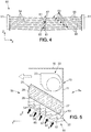
- the gate 50 extending into the air inlet opening is now described in connection with the Figures 2 to 5 .
- the gate 50 comprises two parallel sections 51 spaced from each other in the longitudinal direction X and a plurality of fins 52 extending parallel to each other. Each fin 52 extends in the longitudinal direction X between two ends respectively fixed to the profiles 51.
- the fins 52 have a cross section and a geometry adapted to minimize the impact on the aeraulic input of the first heat exchanger 25 (reduction of losses and therefore of the work of the fan), to protect the first heat exchanger 25 any type of intrusion and to recover the condensates that form on the first heat exchanger 25 when the heat exchange system 1 operates in air conditioner mode.
- the shape and slope of the fins 52 are optimized to treat the volume of indoor air to pass on the first heat exchanger 25, on the one hand, and to treat the volume of condensate to be discharged, on the other.
- each fin 52 is generally V-shaped defining a concavity on an upper surface 53 visible on the figures 3 and 5 , and a convexity on a lower surface 54, visible on the figures 2 and 5 .
- Each fin 52 comprises, in particular, a front wall 55 on the side of a front edge of the gate 50 and a rear wall 56 on the side of a rear edge of the gate 50.
- the front wall 55 is substantially vertical and the wall rear 56 is inclined, for example at an angle less than 45 °, relative to the horizontal plane XY and the vertical plane XZ.
- each fin 52 has, moreover, in the vertical plane XZ, a V shape with two parts extending on either side of a bend 57 with a slope, for example less than 10%, especially less than 5%, preferably between 2 and 4%.
- the fins 52 are fixed to the profiles 51 so as to be spaced from each other in the transverse direction Y and spaced from each other in the vertical direction Z.
- the fins 52 are arranged to deviate from the reference plane P from the rear edge of the grid 50 to the front edge.
- the grid 50 further comprises a channel 60 connecting the fins 52 to each other to ensure continuity of condensate flow between the fins 52 to the fin 52 closest to the rear edge of the grid 50, positioned at the lowest before evacuating them by any appropriate means.
- the channel 60 is central and connects the fins 52 between their ends, at their elbows 57, so that each fin 52 converges to the gutter 60.
- the gutter 60 is composed of a plurality of gutter portions 61 each extending between an opening 62 on the rear wall 56 (oblique) of one of the fins 52 and a notch 63 on the front wall 55 (vertical) of the following fin 52; , located lower.
- one or more differently arranged gutters could be provided.
- the gate 50 is mounted in the air inlet opening of the base 20 of the enclosure 5 with its front edge on the side of the front face 5b of the enclosure 5 and its rear edge on the side of the face rear 5a of the enclosure 5.
- the grid 50 inclined relative to the horizontal plane XY and the vertical plane XZ away from the ground S from its rear edge to its front edge, then extends obliquely, parallel to the first heat exchanger 25, so as to present the lower surface 54 of the front walls 55 of the fins 52 towards the front face 5b of the enclosure 5 ( figures 1 and 4 ).
- the concavity of the upper surfaces 53 of the fins 52 is turned towards the first heat exchanger 25 and the convexity of the lower surfaces 54 of the fins 52 is turned outwards, and in particular the soil S.
- Each of the fins 52 has a length corresponding to a longitudinal dimension of the first heat exchanger 25.
- the fins 52 are shaped so that a projection of the upper surfaces 53 on a horizontal projection plane completely covers a projection of the air inlet opening on the projection plane.
- one end of the rear wall 56 of one of the fins 52 is located in line with one end of the front wall 55 of the fin 52 following.
- the air inlet opening extends over the entire base 20 so that the entire base 20 has been described as oblique.
- the air inlet opening could extend only on a base portion, only this portion of the base being oblique.
- the invention has been described in relation to a base 20 and a grid 50 extending rectilinearly between front and rear edges, parallel to the first heat exchanger 25.
- the base 20 and / or the grid 50 could however extend generally parallel to the first heat exchanger 25 having a slight inclination, plus or minus 20 °, with respect to the first heat exchanger 25.
- the base 20 and / or the grid 50 could have a curvature between their leading and trailing edges and extending generally parallel to the first heat exchanger 25 to the extent that a plane joining the front and rear base edges 20 and / or the grid 50 is parallel to the first heat exchanger 25; or minus 20 °.
Landscapes
- Engineering & Computer Science (AREA)
- Chemical & Material Sciences (AREA)
- Combustion & Propulsion (AREA)
- Mechanical Engineering (AREA)
- General Engineering & Computer Science (AREA)
- Air Filters, Heat-Exchange Apparatuses, And Housings Of Air-Conditioning Units (AREA)
Claims (11)
- Wärmeaustauschsystem (1) zur Konditionierung der Innenluft eines Raums (2), wobei das Wärmeaustauschsystem (1) Folgendes umfasst:- ein Gehäuse (5), umfassend eine Basis (20), die dazu bestimmt ist, gegenüber einem Boden (S) des Raums (2) angeordnet zu werden, und eine Vorderseite (5b) und eine gegenüberliegende Rückseite (5a), die sich in eine Vertikalrichtung (Z) von der Basis (20) erstrecken, wobei das Gehäuse (5) eine Lufteintrittsöffnung, die auf mindestens einem Teil der Basis (20) vorgesehen ist, und eine Luftaustrittsöffnung aufweist,- ein Gitter (50), das sich in der Lufteintrittsöffnung des Gehäuses (5) erstreckt,- einen ersten (25) und einen zweiten (35) Wärmetauscher, von den einer einen Kondensator und der andere einen Verdampfer bildet, wobei der erste Wärmetauscher (25) in dem Gehäuse (5) angeordnet ist und eine Unterseite (26) aufweist, die sich in der Nähe der Basis (20) und gegenüber der Lufteintrittsöffnung befindet,- eine Kühlflüssigkeitsschaltung, die geeignet ist, eine Kühlflüssigkeit in dem ersten (25) und dem zweiten (35) Wärmetauscher zirkulieren zu lassen,wobei das Wärmeaustauschsystem (1) dadurch gekennzeichnet ist, dass der erste Wärmetauscher (25) schräg in dem Gehäuse (5) angeordnet ist, so dass die Unterseite (26) zur Vorderseite (5b) des Gehäuses (5) gerichtet ist,
dass sich mindestens der Teil der Basis (20), auf dem die Lufteintrittsöffnung vorgesehen ist, schräg erstreckt, so dass die Lufteintrittsöffnung zur Vorderseite (5b) des Gehäuses (5) gerichtet ist,
und dass das Gitter (50) eine Vielzahl von zueinander parallelen Lamellen (52) umfasst, wobei jede Lamelle (52) gegenüberliegende Oberseiten (53) und Unterseiten (54) hat, die zu dem ersten Wärmetauscher (25) bzw. nach außen gerichtet sind, wobei sich das Gitter (50) schräg erstreckt, so dass ein Teil der Unterseite (54) der Lamellen (52) zur Vorderseite (5b) des Gehäuses (5) gerichtet ist, wobei die Oberseiten (53) der Lamellen (52) dazu vorgesehen sind, Kondensat zu sammeln, das sich auf dem ersten Wärmetauscher (25) bildet, und wobei die Unterseiten (54) der Lamellen (52) dazu vorgesehen sind, einen inneren Luftdurchgang durch die Lufteintrittsöffnung zu ermöglichen. - Wärmeaustauschsystem (1) nach Anspruch 1, bei dem sich die Basis (20) und der erste Wärmetauscher (25) global parallel zueinander erstrecken, wobei sich das Gitter (50) global parallel zu dem ersten Wärmetauscher (25) erstreckt.
- Wärmeaustauschsystem (1) nach Anspruch 1 oder 2, bei dem die Oberseite (53) jeder Lamelle (52) eine zum ersten Wärmetauscher (25) gewandte Konkavität aufweist, und die Unterseite (54) jeder Lamelle (52) eine nach außen gewandte Konvexität aufweist.
- Wärmeaustauschsystem (1) nach einem der Ansprüche 1 bis 3, bei dem die Lamellen (52) derart ausgeführt sind, dass eine Projektion der Oberseiten (53) auf eine Projektionsfläche senkrecht zur Vertikalrichtung (Z) vollkommen eine Projektion der Lufteintrittsöffnung auf die Projektionsebene abdeckt.
- Wärmeaustauschsystem (1) nach einem der Ansprüche 1 bis 4, bei dem sich jede Lamelle (52) in eine Längsrichtung (X) senkrecht zur Vertikalrichtung (Z) erstreckt, wobei die Lamellen (52) zueinander in eine Transversalrichtung (Y) senkrecht zu der Längsrichtung (X) und der Vertikalrichtung (Z) beabstandet sind, und zueinander in Vertikalrichtung (Z) beabstandet sind.
- Wärmeaustauschsystem (1) nach Anspruch 5, bei dem jede Lamelle (52) einen im Allgemeinen V-förmigen Querschnitt aufweist und eine vordere (55) und eine hintere (56) Wand auf der Seite der Vorderseite (5b) bzw. Rückseite (5a) des Gehäuses (5) umfasst, wobei die vordere Wand (55) im Wesentlichen vertikal und die hintere Wand (56) schräg ist.
- Wärmeaustauschsystem (1) nach einem der Ansprüche 1 bis 6, bei dem das Gitter (50) mindestens eine Rinne (60) umfasst, die die Lamellen (52) miteinander verbindet, wobei jede Lamelle (52) zu der Rinne (60) hin konvergierend ist.
- Wärmeaustauschsystem (1) nach Anspruch 7, bei dem sich jede Lamelle (52) zwischen zwei gegenüberliegenden Enden erstreckt, wobei die Rinne (60) die Lamellen (52) miteinander zwischen den Enden der Lamellen (52) verbindet.
- Wärmeaustauschsystem (1) nach einem der Ansprüche 1 bis 8, ferner umfassend einen Luftkreislauf, der dazu vorgesehen ist, die Innenluft zwischen der Lufteintrittsöffnung und der Luftaustrittsöffnung durch den ersten Wärmetauscher (25) zirkulieren zu lassen, wobei der erste Wärmetauscher (25) einen vorderen (28) und einen hinteren Rand (27) auf der Seite der Vorderseite (5b) bzw. der Rückseite (5a) des Gehäuses (5) aufweist, wobei der Luftkreislauf mindestens einen Ventilator (22) umfasst, der vor dem ersten Wärmetauscher (25), gegenüber der Basis (20) angeordnet ist, wobei sich der Ventilator (22) in einem Abstand, gemessen senkrecht zu der Vertikalrichtung (Z), zwischen dem vorderen (28) und dem hinteren Rand (27) des ersten Wärmetauschers (25) erstreckt und eine Gebläseöffnung (23) aufweist, die im Wesentlichen vor dem vorderen Rand (28) des ersten Wärmetauschers (25) angeordnet ist.
- Wärmeaustauschsystem (1) nach einem der Ansprüche 1 bis 9, bei dem das Gehäuse (5) dazu vorgesehen ist, eine Installation im Raum (2) zu ermöglichen, so dass die Basis (20) in der Nähe des Bodens (S) angeordnet ist, wobei der Raum (5) insbesondere eine Rückwand (11, 31) auf der Rückseite (5a) umfasst, die mit Elementen zur Verankerung an einer Mauer (M) des Raums (2) oder Füßen zum Aufstellen am Boden (S) des Raums (2) versehen ist.
- Wärmeaustauschsystem (1) nach einem der Ansprüche 1 bis 10, umfassend eine innere Einheit, die das Gehäuse (5), den ersten (25) und den zweiten Wärmetauscher (35) und die Kühlflüssigkeitsschaltung einschließt, wobei der erste (25) und der zweite Wärmetauscher (35) und die Kühlflüssigkeitsschaltung in dem Gehäuse (5) angeordnet sind.
Applications Claiming Priority (2)
| Application Number | Priority Date | Filing Date | Title |
|---|---|---|---|
| FR1158715A FR2980560B1 (fr) | 2011-09-28 | 2011-09-28 | Systeme d'echange thermique pour conditionner l'air interieur d'un espace |
| PCT/FR2012/052129 WO2013045801A1 (fr) | 2011-09-28 | 2012-09-25 | Système d'échange thermique pour conditionner l'air intérieur d'un espace |
Publications (2)
| Publication Number | Publication Date |
|---|---|
| EP2761232A1 EP2761232A1 (de) | 2014-08-06 |
| EP2761232B1 true EP2761232B1 (de) | 2017-09-06 |
Family
ID=47071350
Family Applications (1)
| Application Number | Title | Priority Date | Filing Date |
|---|---|---|---|
| EP12775765.6A Not-in-force EP2761232B1 (de) | 2011-09-28 | 2012-09-25 | Wärmeaustauschsystem zur konditionierung von rauminnenluft |
Country Status (3)
| Country | Link |
|---|---|
| EP (1) | EP2761232B1 (de) |
| FR (1) | FR2980560B1 (de) |
| WO (1) | WO2013045801A1 (de) |
Family Cites Families (6)
| Publication number | Priority date | Publication date | Assignee | Title |
|---|---|---|---|---|
| US2130327A (en) * | 1932-12-24 | 1938-09-13 | Baldwin Southwark Corp | Air conditioning apparatus |
| DE1604301B1 (de) * | 1965-04-24 | 1970-01-29 | Steeb Christian | Geraet zum Temperieren eines Raumes |
| US4733542A (en) * | 1986-12-05 | 1988-03-29 | Enviromaster International Corporation | Cabinet for air conditioning system |
| US5533357A (en) * | 1995-02-15 | 1996-07-09 | Carrier Corporation | Air conditioning apparatus |
| KR100214639B1 (ko) * | 1996-12-21 | 1999-08-02 | 구자홍 | 공기조화기의 상방흡입 횡류형 실내기 |
| DE19937083C1 (de) * | 1999-08-06 | 2001-02-15 | Hagenuk Faiveley Gmbh & Co | Tropfenabscheider für Fahrzeuge, insbesondere für Schienenfahrzeuge |
-
2011
- 2011-09-28 FR FR1158715A patent/FR2980560B1/fr active Active
-
2012
- 2012-09-25 EP EP12775765.6A patent/EP2761232B1/de not_active Not-in-force
- 2012-09-25 WO PCT/FR2012/052129 patent/WO2013045801A1/fr not_active Ceased
Non-Patent Citations (1)
| Title |
|---|
| None * |
Also Published As
| Publication number | Publication date |
|---|---|
| EP2761232A1 (de) | 2014-08-06 |
| FR2980560A1 (fr) | 2013-03-29 |
| FR2980560B1 (fr) | 2013-10-18 |
| WO2013045801A1 (fr) | 2013-04-04 |
Similar Documents
| Publication | Publication Date | Title |
|---|---|---|
| EP2633245B1 (de) | Wärmeaustauschsystem zwischen zuluft und abluft und verfahren mit einem solchen system | |
| EP3537082B1 (de) | Gebläsekonvektor mit wärmetauscher und optimierter luftdurchsatzverteilung | |
| FR3055342A1 (fr) | Profile d'accroche permettant le passage d'air et ensemble de plafond comprenant un tel profile | |
| FR2943775A1 (fr) | Echangeur de stockage pourvu d'un materiau stockeur et boucle de climatisation ou circuit de refroidissement comprenant un tel echangeur. | |
| FR2480422A1 (fr) | Appareil d'echange de chaleur et support interne de celui-ci | |
| EP2339253B1 (de) | Wohngebäude mit einem passiven Klimatisierungssystem | |
| FR3048763B1 (fr) | Systeme de rafraichissement, climatisation ou chauffage a unites separees et caisson renfermant l'une des unites | |
| EP2761232A1 (de) | Wärmeaustauschsystem zur klimatisierung in einem raum | |
| FR2991034A1 (fr) | Intercalaire pour echangeur thermique et echangeur thermique associe | |
| EP2633242B1 (de) | Luftwärmetauschersystem zwischen innenluft und aussenluft | |
| FR3136835A1 (fr) | Générateur d’air réversible mobile pour le conditionnement thermique des constructions légères, permanentes ou éphémères | |
| KR100964564B1 (ko) | 공기조화기의 동파 방지용 경사형 코일 | |
| WO2011128755A2 (fr) | Dispositif thermodynamique pour chauffer et/ou climatiser un batiment | |
| FR3055344A1 (fr) | Profile d'accroche permettant le passage d'air et ensemble de plafond comprenant un tel profile | |
| FR2962525A1 (fr) | Dispositif de conditionnement d'air pour prevenir, a basse temperature exterieure, l'apparition de givre sur les pompes a chaleur, et pour ameliorer leur fonctionnement a temperature exterieure elevee | |
| EP1967797A1 (de) | Heizgerät mit verbundenem Luftauslass | |
| FR3007618A1 (fr) | Armoire d'exterieur a rafraichissement aeraulique | |
| EP4127569B1 (de) | Kühl- oder heizdecken und wänden | |
| WO2023099555A1 (fr) | Dispositif émetteur de chaleur ou de froid et système de chauffage ou de rafraichissement intégrant ce dispositif | |
| FR3167196A1 (fr) | Dispositif de refroidissement ou de chauffage de l’air ambiant dans un espace intérieur, plus particulièrement dans un espace intérieur d’un bâtiment. | |
| FR2844774A1 (fr) | Armoire climatisee perfectionnee pour equipements, notamment de telephonie | |
| FR3024216A1 (fr) | Systeme de rafraichissement, climatisation ou chauffage a unites separees et caisson renfermant l'une des unites | |
| FR2889299A1 (fr) | Element echangeur de temperature realise par extrusion et ses applications | |
| CA3192478A1 (fr) | Systeme de chauffage solaire | |
| WO2011018332A1 (fr) | Echangeur de chaleur à au moins deux passes et boucle de climatisation comprenant un tel échangeur de chaleur. |
Legal Events
| Date | Code | Title | Description |
|---|---|---|---|
| PUAI | Public reference made under article 153(3) epc to a published international application that has entered the european phase |
Free format text: ORIGINAL CODE: 0009012 |
|
| 17P | Request for examination filed |
Effective date: 20140328 |
|
| AK | Designated contracting states |
Kind code of ref document: A1 Designated state(s): AL AT BE BG CH CY CZ DE DK EE ES FI FR GB GR HR HU IE IS IT LI LT LU LV MC MK MT NL NO PL PT RO RS SE SI SK SM TR |
|
| DAX | Request for extension of the european patent (deleted) | ||
| GRAP | Despatch of communication of intention to grant a patent |
Free format text: ORIGINAL CODE: EPIDOSNIGR1 |
|
| STAA | Information on the status of an ep patent application or granted ep patent |
Free format text: STATUS: GRANT OF PATENT IS INTENDED |
|
| INTG | Intention to grant announced |
Effective date: 20170511 |
|
| GRAS | Grant fee paid |
Free format text: ORIGINAL CODE: EPIDOSNIGR3 |
|
| GRAA | (expected) grant |
Free format text: ORIGINAL CODE: 0009210 |
|
| STAA | Information on the status of an ep patent application or granted ep patent |
Free format text: STATUS: THE PATENT HAS BEEN GRANTED |
|
| AK | Designated contracting states |
Kind code of ref document: B1 Designated state(s): AL AT BE BG CH CY CZ DE DK EE ES FI FR GB GR HR HU IE IS IT LI LT LU LV MC MK MT NL NO PL PT RO RS SE SI SK SM TR |
|
| REG | Reference to a national code |
Ref country code: GB Ref legal event code: FG4D Free format text: NOT ENGLISH |
|
| REG | Reference to a national code |
Ref country code: CH Ref legal event code: EP Ref country code: AT Ref legal event code: REF Ref document number: 926311 Country of ref document: AT Kind code of ref document: T Effective date: 20170915 |
|
| REG | Reference to a national code |
Ref country code: IE Ref legal event code: FG4D Free format text: LANGUAGE OF EP DOCUMENT: FRENCH |
|
| REG | Reference to a national code |
Ref country code: DE Ref legal event code: R096 Ref document number: 602012037004 Country of ref document: DE |
|
| REG | Reference to a national code |
Ref country code: FR Ref legal event code: PLFP Year of fee payment: 6 |
|
| REG | Reference to a national code |
Ref country code: NL Ref legal event code: MP Effective date: 20170906 |
|
| REG | Reference to a national code |
Ref country code: LT Ref legal event code: MG4D |
|
| PG25 | Lapsed in a contracting state [announced via postgrant information from national office to epo] |
Ref country code: HR Free format text: LAPSE BECAUSE OF FAILURE TO SUBMIT A TRANSLATION OF THE DESCRIPTION OR TO PAY THE FEE WITHIN THE PRESCRIBED TIME-LIMIT Effective date: 20170906 Ref country code: LT Free format text: LAPSE BECAUSE OF FAILURE TO SUBMIT A TRANSLATION OF THE DESCRIPTION OR TO PAY THE FEE WITHIN THE PRESCRIBED TIME-LIMIT Effective date: 20170906 Ref country code: NO Free format text: LAPSE BECAUSE OF FAILURE TO SUBMIT A TRANSLATION OF THE DESCRIPTION OR TO PAY THE FEE WITHIN THE PRESCRIBED TIME-LIMIT Effective date: 20171206 Ref country code: SE Free format text: LAPSE BECAUSE OF FAILURE TO SUBMIT A TRANSLATION OF THE DESCRIPTION OR TO PAY THE FEE WITHIN THE PRESCRIBED TIME-LIMIT Effective date: 20170906 Ref country code: FI Free format text: LAPSE BECAUSE OF FAILURE TO SUBMIT A TRANSLATION OF THE DESCRIPTION OR TO PAY THE FEE WITHIN THE PRESCRIBED TIME-LIMIT Effective date: 20170906 |
|
| REG | Reference to a national code |
Ref country code: AT Ref legal event code: MK05 Ref document number: 926311 Country of ref document: AT Kind code of ref document: T Effective date: 20170906 |
|
| PG25 | Lapsed in a contracting state [announced via postgrant information from national office to epo] |
Ref country code: RS Free format text: LAPSE BECAUSE OF FAILURE TO SUBMIT A TRANSLATION OF THE DESCRIPTION OR TO PAY THE FEE WITHIN THE PRESCRIBED TIME-LIMIT Effective date: 20170906 Ref country code: BG Free format text: LAPSE BECAUSE OF FAILURE TO SUBMIT A TRANSLATION OF THE DESCRIPTION OR TO PAY THE FEE WITHIN THE PRESCRIBED TIME-LIMIT Effective date: 20171206 Ref country code: GR Free format text: LAPSE BECAUSE OF FAILURE TO SUBMIT A TRANSLATION OF THE DESCRIPTION OR TO PAY THE FEE WITHIN THE PRESCRIBED TIME-LIMIT Effective date: 20171207 Ref country code: ES Free format text: LAPSE BECAUSE OF FAILURE TO SUBMIT A TRANSLATION OF THE DESCRIPTION OR TO PAY THE FEE WITHIN THE PRESCRIBED TIME-LIMIT Effective date: 20170906 Ref country code: LV Free format text: LAPSE BECAUSE OF FAILURE TO SUBMIT A TRANSLATION OF THE DESCRIPTION OR TO PAY THE FEE WITHIN THE PRESCRIBED TIME-LIMIT Effective date: 20170906 |
|
| PG25 | Lapsed in a contracting state [announced via postgrant information from national office to epo] |
Ref country code: NL Free format text: LAPSE BECAUSE OF FAILURE TO SUBMIT A TRANSLATION OF THE DESCRIPTION OR TO PAY THE FEE WITHIN THE PRESCRIBED TIME-LIMIT Effective date: 20170906 |
|
| REG | Reference to a national code |
Ref country code: DE Ref legal event code: R119 Ref document number: 602012037004 Country of ref document: DE |
|
| PG25 | Lapsed in a contracting state [announced via postgrant information from national office to epo] |
Ref country code: RO Free format text: LAPSE BECAUSE OF FAILURE TO SUBMIT A TRANSLATION OF THE DESCRIPTION OR TO PAY THE FEE WITHIN THE PRESCRIBED TIME-LIMIT Effective date: 20170906 Ref country code: CZ Free format text: LAPSE BECAUSE OF FAILURE TO SUBMIT A TRANSLATION OF THE DESCRIPTION OR TO PAY THE FEE WITHIN THE PRESCRIBED TIME-LIMIT Effective date: 20170906 Ref country code: PL Free format text: LAPSE BECAUSE OF FAILURE TO SUBMIT A TRANSLATION OF THE DESCRIPTION OR TO PAY THE FEE WITHIN THE PRESCRIBED TIME-LIMIT Effective date: 20170906 |
|
| REG | Reference to a national code |
Ref country code: CH Ref legal event code: PL |
|
| PG25 | Lapsed in a contracting state [announced via postgrant information from national office to epo] |
Ref country code: SK Free format text: LAPSE BECAUSE OF FAILURE TO SUBMIT A TRANSLATION OF THE DESCRIPTION OR TO PAY THE FEE WITHIN THE PRESCRIBED TIME-LIMIT Effective date: 20170906 Ref country code: SM Free format text: LAPSE BECAUSE OF FAILURE TO SUBMIT A TRANSLATION OF THE DESCRIPTION OR TO PAY THE FEE WITHIN THE PRESCRIBED TIME-LIMIT Effective date: 20170906 Ref country code: AT Free format text: LAPSE BECAUSE OF FAILURE TO SUBMIT A TRANSLATION OF THE DESCRIPTION OR TO PAY THE FEE WITHIN THE PRESCRIBED TIME-LIMIT Effective date: 20170906 Ref country code: EE Free format text: LAPSE BECAUSE OF FAILURE TO SUBMIT A TRANSLATION OF THE DESCRIPTION OR TO PAY THE FEE WITHIN THE PRESCRIBED TIME-LIMIT Effective date: 20170906 Ref country code: IS Free format text: LAPSE BECAUSE OF FAILURE TO SUBMIT A TRANSLATION OF THE DESCRIPTION OR TO PAY THE FEE WITHIN THE PRESCRIBED TIME-LIMIT Effective date: 20180106 Ref country code: IT Free format text: LAPSE BECAUSE OF FAILURE TO SUBMIT A TRANSLATION OF THE DESCRIPTION OR TO PAY THE FEE WITHIN THE PRESCRIBED TIME-LIMIT Effective date: 20170906 |
|
| REG | Reference to a national code |
Ref country code: IE Ref legal event code: MM4A |
|
| REG | Reference to a national code |
Ref country code: BE Ref legal event code: MM Effective date: 20170930 |
|
| PG25 | Lapsed in a contracting state [announced via postgrant information from national office to epo] |
Ref country code: MC Free format text: LAPSE BECAUSE OF FAILURE TO SUBMIT A TRANSLATION OF THE DESCRIPTION OR TO PAY THE FEE WITHIN THE PRESCRIBED TIME-LIMIT Effective date: 20170906 Ref country code: LU Free format text: LAPSE BECAUSE OF NON-PAYMENT OF DUE FEES Effective date: 20170925 |
|
| PLBE | No opposition filed within time limit |
Free format text: ORIGINAL CODE: 0009261 |
|
| STAA | Information on the status of an ep patent application or granted ep patent |
Free format text: STATUS: NO OPPOSITION FILED WITHIN TIME LIMIT |
|
| PG25 | Lapsed in a contracting state [announced via postgrant information from national office to epo] |
Ref country code: DK Free format text: LAPSE BECAUSE OF FAILURE TO SUBMIT A TRANSLATION OF THE DESCRIPTION OR TO PAY THE FEE WITHIN THE PRESCRIBED TIME-LIMIT Effective date: 20170906 Ref country code: DE Free format text: LAPSE BECAUSE OF NON-PAYMENT OF DUE FEES Effective date: 20180404 Ref country code: LI Free format text: LAPSE BECAUSE OF NON-PAYMENT OF DUE FEES Effective date: 20170930 Ref country code: CH Free format text: LAPSE BECAUSE OF NON-PAYMENT OF DUE FEES Effective date: 20170930 Ref country code: IE Free format text: LAPSE BECAUSE OF NON-PAYMENT OF DUE FEES Effective date: 20170925 |
|
| 26N | No opposition filed |
Effective date: 20180607 |
|
| GBPC | Gb: european patent ceased through non-payment of renewal fee |
Effective date: 20171206 |
|
| PG25 | Lapsed in a contracting state [announced via postgrant information from national office to epo] |
Ref country code: SI Free format text: LAPSE BECAUSE OF FAILURE TO SUBMIT A TRANSLATION OF THE DESCRIPTION OR TO PAY THE FEE WITHIN THE PRESCRIBED TIME-LIMIT Effective date: 20170906 Ref country code: BE Free format text: LAPSE BECAUSE OF NON-PAYMENT OF DUE FEES Effective date: 20170930 |
|
| PG25 | Lapsed in a contracting state [announced via postgrant information from national office to epo] |
Ref country code: MT Free format text: LAPSE BECAUSE OF FAILURE TO SUBMIT A TRANSLATION OF THE DESCRIPTION OR TO PAY THE FEE WITHIN THE PRESCRIBED TIME-LIMIT Effective date: 20170906 |
|
| REG | Reference to a national code |
Ref country code: FR Ref legal event code: PLFP Year of fee payment: 7 |
|
| PG25 | Lapsed in a contracting state [announced via postgrant information from national office to epo] |
Ref country code: GB Free format text: LAPSE BECAUSE OF NON-PAYMENT OF DUE FEES Effective date: 20171206 |
|
| PG25 | Lapsed in a contracting state [announced via postgrant information from national office to epo] |
Ref country code: HU Free format text: LAPSE BECAUSE OF FAILURE TO SUBMIT A TRANSLATION OF THE DESCRIPTION OR TO PAY THE FEE WITHIN THE PRESCRIBED TIME-LIMIT; INVALID AB INITIO Effective date: 20120925 |
|
| PG25 | Lapsed in a contracting state [announced via postgrant information from national office to epo] |
Ref country code: CY Free format text: LAPSE BECAUSE OF NON-PAYMENT OF DUE FEES Effective date: 20170906 |
|
| PG25 | Lapsed in a contracting state [announced via postgrant information from national office to epo] |
Ref country code: MK Free format text: LAPSE BECAUSE OF FAILURE TO SUBMIT A TRANSLATION OF THE DESCRIPTION OR TO PAY THE FEE WITHIN THE PRESCRIBED TIME-LIMIT Effective date: 20170906 |
|
| PG25 | Lapsed in a contracting state [announced via postgrant information from national office to epo] |
Ref country code: TR Free format text: LAPSE BECAUSE OF FAILURE TO SUBMIT A TRANSLATION OF THE DESCRIPTION OR TO PAY THE FEE WITHIN THE PRESCRIBED TIME-LIMIT Effective date: 20170906 |
|
| PG25 | Lapsed in a contracting state [announced via postgrant information from national office to epo] |
Ref country code: PT Free format text: LAPSE BECAUSE OF FAILURE TO SUBMIT A TRANSLATION OF THE DESCRIPTION OR TO PAY THE FEE WITHIN THE PRESCRIBED TIME-LIMIT Effective date: 20170906 |
|
| PG25 | Lapsed in a contracting state [announced via postgrant information from national office to epo] |
Ref country code: AL Free format text: LAPSE BECAUSE OF FAILURE TO SUBMIT A TRANSLATION OF THE DESCRIPTION OR TO PAY THE FEE WITHIN THE PRESCRIBED TIME-LIMIT Effective date: 20170906 |
|
| PGFP | Annual fee paid to national office [announced via postgrant information from national office to epo] |
Ref country code: FR Payment date: 20210824 Year of fee payment: 10 |
|
| PG25 | Lapsed in a contracting state [announced via postgrant information from national office to epo] |
Ref country code: FR Free format text: LAPSE BECAUSE OF NON-PAYMENT OF DUE FEES Effective date: 20220930 |