EP2761863B1 - Détection de défauts d'impression - Google Patents
Détection de défauts d'impression Download PDFInfo
- Publication number
- EP2761863B1 EP2761863B1 EP11873051.4A EP11873051A EP2761863B1 EP 2761863 B1 EP2761863 B1 EP 2761863B1 EP 11873051 A EP11873051 A EP 11873051A EP 2761863 B1 EP2761863 B1 EP 2761863B1
- Authority
- EP
- European Patent Office
- Prior art keywords
- image
- digital image
- color
- matched reference
- scanned
- Prior art date
- Legal status (The legal status is an assumption and is not a legal conclusion. Google has not performed a legal analysis and makes no representation as to the accuracy of the status listed.)
- Not-in-force
Links
Images



Classifications
-
- G—PHYSICS
- G06—COMPUTING OR CALCULATING; COUNTING
- G06T—IMAGE DATA PROCESSING OR GENERATION, IN GENERAL
- G06T7/00—Image analysis
- G06T7/0002—Inspection of images, e.g. flaw detection
- G06T7/0004—Industrial image inspection
- G06T7/001—Industrial image inspection using an image reference approach
-
- G—PHYSICS
- G03—PHOTOGRAPHY; CINEMATOGRAPHY; ANALOGOUS TECHNIQUES USING WAVES OTHER THAN OPTICAL WAVES; ELECTROGRAPHY; HOLOGRAPHY
- G03G—ELECTROGRAPHY; ELECTROPHOTOGRAPHY; MAGNETOGRAPHY
- G03G15/00—Apparatus for electrographic processes using a charge pattern
- G03G15/50—Machine control of apparatus for electrographic processes using a charge pattern, e.g. regulating differents parts of the machine, multimode copiers, microprocessor control
- G03G15/5062—Machine control of apparatus for electrographic processes using a charge pattern, e.g. regulating differents parts of the machine, multimode copiers, microprocessor control by measuring the characteristics of an image on the copy material
-
- G—PHYSICS
- G06—COMPUTING OR CALCULATING; COUNTING
- G06T—IMAGE DATA PROCESSING OR GENERATION, IN GENERAL
- G06T7/00—Image analysis
- G06T7/0002—Inspection of images, e.g. flaw detection
-
- G—PHYSICS
- G06—COMPUTING OR CALCULATING; COUNTING
- G06T—IMAGE DATA PROCESSING OR GENERATION, IN GENERAL
- G06T7/00—Image analysis
- G06T7/90—Determination of colour characteristics
-
- H—ELECTRICITY
- H04—ELECTRIC COMMUNICATION TECHNIQUE
- H04N—PICTORIAL COMMUNICATION, e.g. TELEVISION
- H04N1/00—Scanning, transmission or reproduction of documents or the like, e.g. facsimile transmission; Details thereof
- H04N1/00002—Diagnosis, testing or measuring; Detecting, analysing or monitoring not otherwise provided for
- H04N1/00007—Diagnosis, testing or measuring; Detecting, analysing or monitoring not otherwise provided for relating to particular apparatus or devices
- H04N1/00015—Reproducing apparatus
-
- H—ELECTRICITY
- H04—ELECTRIC COMMUNICATION TECHNIQUE
- H04N—PICTORIAL COMMUNICATION, e.g. TELEVISION
- H04N1/00—Scanning, transmission or reproduction of documents or the like, e.g. facsimile transmission; Details thereof
- H04N1/00002—Diagnosis, testing or measuring; Detecting, analysing or monitoring not otherwise provided for
- H04N1/00007—Diagnosis, testing or measuring; Detecting, analysing or monitoring not otherwise provided for relating to particular apparatus or devices
- H04N1/00023—Colour systems
-
- H—ELECTRICITY
- H04—ELECTRIC COMMUNICATION TECHNIQUE
- H04N—PICTORIAL COMMUNICATION, e.g. TELEVISION
- H04N1/00—Scanning, transmission or reproduction of documents or the like, e.g. facsimile transmission; Details thereof
- H04N1/00002—Diagnosis, testing or measuring; Detecting, analysing or monitoring not otherwise provided for
- H04N1/00026—Methods therefor
- H04N1/00045—Methods therefor using a reference pattern designed for the purpose, e.g. a test chart
-
- H—ELECTRICITY
- H04—ELECTRIC COMMUNICATION TECHNIQUE
- H04N—PICTORIAL COMMUNICATION, e.g. TELEVISION
- H04N1/00—Scanning, transmission or reproduction of documents or the like, e.g. facsimile transmission; Details thereof
- H04N1/00002—Diagnosis, testing or measuring; Detecting, analysing or monitoring not otherwise provided for
- H04N1/00026—Methods therefor
- H04N1/00047—Methods therefor using an image not specifically designed for the purpose
-
- H—ELECTRICITY
- H04—ELECTRIC COMMUNICATION TECHNIQUE
- H04N—PICTORIAL COMMUNICATION, e.g. TELEVISION
- H04N1/00—Scanning, transmission or reproduction of documents or the like, e.g. facsimile transmission; Details thereof
- H04N1/00002—Diagnosis, testing or measuring; Detecting, analysing or monitoring not otherwise provided for
- H04N1/00026—Methods therefor
- H04N1/0005—Methods therefor in service, i.e. during normal operation
-
- H—ELECTRICITY
- H04—ELECTRIC COMMUNICATION TECHNIQUE
- H04N—PICTORIAL COMMUNICATION, e.g. TELEVISION
- H04N1/00—Scanning, transmission or reproduction of documents or the like, e.g. facsimile transmission; Details thereof
- H04N1/00002—Diagnosis, testing or measuring; Detecting, analysing or monitoring not otherwise provided for
- H04N1/00026—Methods therefor
- H04N1/00063—Methods therefor using at least a part of the apparatus itself, e.g. self-testing
-
- H—ELECTRICITY
- H04—ELECTRIC COMMUNICATION TECHNIQUE
- H04N—PICTORIAL COMMUNICATION, e.g. TELEVISION
- H04N1/00—Scanning, transmission or reproduction of documents or the like, e.g. facsimile transmission; Details thereof
- H04N1/00002—Diagnosis, testing or measuring; Detecting, analysing or monitoring not otherwise provided for
- H04N1/00026—Methods therefor
- H04N1/00068—Calculating or estimating
-
- H—ELECTRICITY
- H04—ELECTRIC COMMUNICATION TECHNIQUE
- H04N—PICTORIAL COMMUNICATION, e.g. TELEVISION
- H04N1/00—Scanning, transmission or reproduction of documents or the like, e.g. facsimile transmission; Details thereof
- H04N1/00002—Diagnosis, testing or measuring; Detecting, analysing or monitoring not otherwise provided for
- H04N1/00071—Diagnosis, testing or measuring; Detecting, analysing or monitoring not otherwise provided for characterised by the action taken
- H04N1/00082—Adjusting or controlling
-
- H—ELECTRICITY
- H04—ELECTRIC COMMUNICATION TECHNIQUE
- H04N—PICTORIAL COMMUNICATION, e.g. TELEVISION
- H04N1/00—Scanning, transmission or reproduction of documents or the like, e.g. facsimile transmission; Details thereof
- H04N1/46—Colour picture communication systems
- H04N1/56—Processing of colour picture signals
-
- H—ELECTRICITY
- H04—ELECTRIC COMMUNICATION TECHNIQUE
- H04N—PICTORIAL COMMUNICATION, e.g. TELEVISION
- H04N1/00—Scanning, transmission or reproduction of documents or the like, e.g. facsimile transmission; Details thereof
- H04N1/46—Colour picture communication systems
- H04N1/56—Processing of colour picture signals
- H04N1/60—Colour correction or control
- H04N1/603—Colour correction or control controlled by characteristics of the picture signal generator or the picture reproducer
- H04N1/6033—Colour correction or control controlled by characteristics of the picture signal generator or the picture reproducer using test pattern analysis
- H04N1/6036—Colour correction or control controlled by characteristics of the picture signal generator or the picture reproducer using test pattern analysis involving periodic tests or tests during use of the machine
-
- H—ELECTRICITY
- H04—ELECTRIC COMMUNICATION TECHNIQUE
- H04N—PICTORIAL COMMUNICATION, e.g. TELEVISION
- H04N1/00—Scanning, transmission or reproduction of documents or the like, e.g. facsimile transmission; Details thereof
- H04N1/46—Colour picture communication systems
- H04N1/56—Processing of colour picture signals
- H04N1/60—Colour correction or control
- H04N1/603—Colour correction or control controlled by characteristics of the picture signal generator or the picture reproducer
- H04N1/6033—Colour correction or control controlled by characteristics of the picture signal generator or the picture reproducer using test pattern analysis
- H04N1/6047—Colour correction or control controlled by characteristics of the picture signal generator or the picture reproducer using test pattern analysis wherein the test pattern is part of an arbitrary user image
-
- G—PHYSICS
- G06—COMPUTING OR CALCULATING; COUNTING
- G06K—GRAPHICAL DATA READING; PRESENTATION OF DATA; RECORD CARRIERS; HANDLING RECORD CARRIERS
- G06K15/00—Arrangements for producing a permanent visual presentation of the output data, e.g. computer output printers
- G06K15/02—Arrangements for producing a permanent visual presentation of the output data, e.g. computer output printers using printers
-
- G—PHYSICS
- G06—COMPUTING OR CALCULATING; COUNTING
- G06T—IMAGE DATA PROCESSING OR GENERATION, IN GENERAL
- G06T2207/00—Indexing scheme for image analysis or image enhancement
- G06T2207/10—Image acquisition modality
- G06T2207/10004—Still image; Photographic image
-
- G—PHYSICS
- G06—COMPUTING OR CALCULATING; COUNTING
- G06T—IMAGE DATA PROCESSING OR GENERATION, IN GENERAL
- G06T2207/00—Indexing scheme for image analysis or image enhancement
- G06T2207/30—Subject of image; Context of image processing
- G06T2207/30108—Industrial image inspection
- G06T2207/30144—Printing quality
Definitions
- Industrial printing systems are used to print images onto large volumes of substrates such as paper.
- the images are often stored as a digital image that is sent to the printing system to be printed. It is often important to an operator of such printing systems that any defects in the printing process be detected so that the problem can be quickly fixed before subsequent defective images are printed.
- a defect is any unwanted discoloration, marking, or characteristic of the printed image.
- US2011/0149331 discloses a method for detecting print errors in which a source document is used to produce a printed image which is scanned. The scanned image is compared to an expected digital representation which is generated by applying modelled parameters of the printing and scanning system to the source document.
- US2008/0212844 discloses a method of determining deviations from a reference image, the reference image being a scanned image which has been determined to be of good quality.
- US2005/240376 discloses a method of detecting printing defects in which an original image is adjusted to model image capturing techniques of a camera capturing an image of a printed image, before being compared to the captured image.
- US2011/069894 discloses a method of detecting printing defects in which a reference image may be formatted or downscaled in resolution to match the image resolution produced by a scanner, before being compared to a scanned image.
- the present specification discloses methods and systems for detecting defects within printed images.
- the methods and systems disclosed herein are particularly effective in detecting low contrast defects.
- an image that has been printed is scanned and put into a digital format.
- This scanning process can be done by an inline scanner that scans the image immediately after it has been printed onto the paper and as the paper continues to move along its path. Because the scanning process does not produce an exact replica of the original digital image, a color adjustment function is then applied to the original digital image used to print the image. This color adjustment function creates a matched reference image. The colors of the matched reference image are adjusted to better match the coloring of the scanned image. More detail on an example of how such a function may work will be provided below.
- the matched reference image is then compared with the scanned image.
- the comparison function used to compare this function is designed to be robust enough to handle slight coloring variations and misregistration issues.
- a misregistration issue refers to an alignment issue between the scanned image and the matched reference image for purposes of the comparison.
- Significant differences between the scanned image and the matched reference image may be identified as defects. More details on how the comparison function may work will be described below.
- a validation process may be used to ensure that differences are a result of actual defects and not random errors in the comparison function.
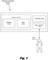
- Fig. 1 is a diagram showing an illustrative physical computing system (100) that can be used to operate a printing system.
- the physical computing system (100) includes a memory (102) having software (104) and data (106) stored thereon.
- the physical computing system (100) also includes a processor (108) and a user interface (110).
- RAM Random Access Memory
- the physical computing system (100) also includes a processor (108) for executing the software (104) and using or updating the data (106) stored in memory (102).
- the software (104) may include an operating system. An operating system allows other applications to interact properly with the hardware of the physical computing system.
- a user interface (110) may provide a means for the user (112) to interact with the physical computing system (100).
- the user interface may include any collection of devices for interfacing with a human user (112).
- the user interface (110) may include an input device such as a keyboard or mouse and an output device such as a monitor.
- Fig. 2 is a diagram showing an illustrative printing system (200).
- an industrial printing system may include a printing subsystem (204) and a scanning subsystem (206). Both the printing subsystem (204) and the scanning subsystem (206) may be controlled by a computing system (202).
- the printing subsystem (204) prints images onto a substrate (208) passing in relation to one or more printheads associated with the printing subsystem. After these images have been printed onto the substrate (208), the scanning subsystem (206) can scan those printed images for the purpose of detecting defects within those printed images.
- the computing system (202) can compare the scanned image with the digital image that was printed onto the substrate (208) in order to determine if any defects are present. By immediately scanning printed images, defects can be detected and corrected before subsequent defective images are printed.
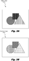
- Fig. 3A is a diagram showing an illustrative digital image.
- the images printed by printing systems are first stored as digital images.
- the digital image is created by a separate computing system and transferred to the printing system.
- the colors within a digital image are often represented using a Red Greed Blue (RGB) color scheme.
- RGB Red Greed Blue
- a digital image is represented by storing a value for each individual pixel within the image. Each pixel stores intensity values for red, blue, and green. The varying intensity between these colors defines the variety of colors able to be formed by the RGB color scheme.
- the color scheme is converted into the Cyan, Magenta, Yellow, and blacK (CMYK) color scheme.
- CMYK Cyan, Magenta, Yellow, and blacK
- a standard printer uses half-toning functions with cyan, magenta, yellow, and black inks in order to create the appropriate image on the substrate.
- certain methods may be used to provide a relatively accurate conversion between the RGB color scheme and the CMYK color scheme, the scanning process does not quite capture the colors in a consistent manner.
- Fig. 3B is a diagram showing an illustrative scanned image (302).
- the scanning process also introduces variations.
- the scanning process can introduce color instabilities, noise, drift and other issues that cause inconsistencies.
- Scanning hardware detects the colors that were printed onto the substrate and scanning software converts the image into a digital scanned image. The comparison between the digital image (300) and the scanned image (302) shows a slight variation in coloring.
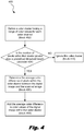
- Fig. 4 is a flowchart showing an illustrative process for creating a matched reference image.
- the digital image is first adjusted to better match the coloring of the scanned image.
- the adjusted digital image will be referred to as the matched reference image.
- the color matching process (400) factors in the colors on each color channel.
- a color cluster is defined (block 402) that includes a range of color values from each channel.
- a color value refers to the digital number used to represent the intensity of a particular color at a particular pixel.
- the variation in color intensity for the red channel may be represented as an eight bit value.
- the color value may range from 0 - 255.
- the color matching process may define a cluster with red values between 20 and 30, green values between 50 and 60, and blue values between 120 and 130.
- the color matching process will then determine (decision 404) whether or not the number of pixels within this color cluster exceeds a predefined threshold level.
- this predefined threshold value may be 50 pixels.
- this color cluster is ignored (block 410). This is because there may not be enough pixels within the image within this color cluster to accurately match to the scanned image. Thus, it may be more beneficial to ignore these pixels.
- pixels within that cluster can be matched. This can be done by determining (block 406) the difference between the average color within that range from the digital image and the average color within that range from the scanned image. This average difference is then added (block 408) to the color values for each pixel within that color cluster to form the matched reference image. This process is then performed for the remaining color value ranges within each of the color channels.
- the scanning system will read the same color on the printed image differently. This may be due to a variety of factors including the varying distance between the substrate and the scanner sensors. This varying distance is dues to the motion of the paper as it moves underneath the scanner. These variations are referred to as the scanner instability. This instability tends to be greater for brighter colors than for darker colors. In order to compensate for this instability, a stability measure is created for each color value range of each channel.
- the stability measure can be defined as the standard deviation in the difference between the scanned image colors and the digital image colors within the color value range.
- the standard deviation is a measurement of the variation from the mean value.
- the stability measure from each color value range from each color channel can be combined to form a stability map. With the stability map and the matched reference image, a more accurate comparison can be made to the scanned image for the purpose of detecting defects.
- Fig. 5 is a diagram showing an illustrative matched reference image (500).
- the matched reference image includes omitted regions (502).
- the omitted regions (502) are those in which the color value of the pixels was a value within a range that had less than the predefined threshold number of pixels. Thus, these pixels were ignored during the matching process. However, the majority of the picture has been matched and appears similar in color to the scanned image (e.g. 302, Fig. 302).
- Fig. 6 is a diagram showing an illustrative process for comparing the similarity between a matched reference image and a scanned image. After the matched reference image has been created, it can be compared with the scanned image. Significant differences between the matched reference image and the scanned image may indicate a defect within the printed image. According to certain illustrative examples, the process includes comparing (block 602) the average color value between corresponding regions of the matched reference image and the scanned image. The process further includes using (block 604) the comparison to form a similarity image that has darker regions for more dissimilar regions.
- the similarity image may be represented in values between zero and one. A value of zero indicates no similarity and a value of one indicates absolute similarity.
- This similarity image can be rendered as a grayscale image with values closer to zero being darker and values closer to one being lighter.
- the manner in which the similarity is measured is designed to be robust against the variations between the matched reference image and the scanned image which may still exist. Additionally, the similarity measurement is robust against spatial misregistration between the matched reference image and the scanned image.
- the similarity measure may start by measuring the luminance similarity between two corresponding patches from the matched reference image and the scanned image.
- Luminance is a measurement of the brightness of a color or region of colors.
- a patch may be a group of pixels such as a 5x5 square or a 9x9 square of pixels.
- the comparison of two patches may be referred to as the comparison between patch A and patch B.
- CALum context aware luminance
- a B C min 1 SPLum A B selfLum C
- CALum(A, B, C) the context aware luminance between patches A, B, and C
- selfLum C Lum 0.5 + C / 2 , 0.5 ⁇ C / 2
- Lum a , b 2 ⁇ a ⁇ b / ⁇ a 2 + ⁇ b 2 .
- CALum(A, B, C) can be determined where A is a patch from the scanned image, B is a corresponding patch from the matched reference image, and C is a corresponding patch from the stability map. This function can be applied to each color channel and the pixel-wise minimum between each color channel can be used to form the similarity image.
- Fig. 7 is a diagram showing an illustrative similarity image (700).
- the similarity image (700) may be a grayscale image where values closer to zero are represented by darker shades of gray and values closer to one are represented by lighter shades of gray.
- various anomalous regions (702) where darker colors exist will be present.
- various noise regions (704) may be present. These noise regions (704) may be anomalous but do not necessarily represent a defect. For example, variations in the scanning system and anomalies in the similarity measurement function may lead to various noise regions (704) which do not actually correspond to a defect.
- a validation process may be performed.
- Fig. 8 is a diagram showing an illustrative process for validating defects.
- the defect validation process (800) may involve analyzing the coloring within the boundary (806) of a region on the scanned image that corresponds with the anomalous region of the similarity image. The inside region (804) of region boundary (806) is then compared with the coloring immediately outside (802) of the region boundary (806).
- the coloring between the outside region (802) and the inside region (804) are similar, then it is likely that the anomalous region is not a defect. However, if the inside region (804) and the outside region (802) are somewhat different, then it is likely that the anomalous region within the similarity image does in fact correspond to a defect.
- Various methods of comparing the coloring between the inside region and the outside region may be used such as comparing the average color between the two regions.
- Fig. 9 is a flowchart showing an illustrative method (900) for detecting image defects.
- the method (900) includes, with a physical computing system, creating (block 902) a matched reference image from a digital image, colors of the matched reference image being closer matched to a scanned image of the digital image.
- the method further includes, determining (block 904) a color difference between corresponding points on the matched reference and the scanned image. Determining this difference may be done by creating a similarity image that represents differences with a value from zero to one. A value closer to zero indicates dissimilarity while a value closer to one indicates similarity.
- the method further includes, with the physical computing system, identifying (block 906) points that have the color distance greater than a predefined threshold as potential defects. These points that have a color distance greater than a predefined threshold may be manifested in the similarity image as anomalous regions.
- the anomalous regions may be darker regions indicating more dissimilarity.
- an effective method for determining defects in printed images is realized.
- the methods and systems described herein are particularly effective at determining low contrast defects.
- the methods are robust enough to handle color variations in the scanned image as well as spatial misregistration between the scanned image and the reference image.
Landscapes
- Engineering & Computer Science (AREA)
- Multimedia (AREA)
- Signal Processing (AREA)
- Health & Medical Sciences (AREA)
- Biomedical Technology (AREA)
- General Health & Medical Sciences (AREA)
- General Physics & Mathematics (AREA)
- Physics & Mathematics (AREA)
- Computer Vision & Pattern Recognition (AREA)
- Theoretical Computer Science (AREA)
- Quality & Reliability (AREA)
- Microelectronics & Electronic Packaging (AREA)
- Facsimile Image Signal Circuits (AREA)
- Image Analysis (AREA)
- Image Processing (AREA)
- Investigating Materials By The Use Of Optical Means Adapted For Particular Applications (AREA)
- Color Image Communication Systems (AREA)
Claims (13)
- Procédé de détection de défauts d'impression dans une image imprimée, le procédé comprenant :avec un système informatique (100), la réception d'une image numérisée (302), l'image numérisée étant une numérisation de l'image imprimée, l'image imprimée étant formée en imprimant une image numérique d'origine sur un substrat ;le procédé comprenant en outre les étapes suivantes :avec un système informatique (100), la création d'une image numérique de référence adaptée (500) à partir de l'image numérique d'origine en ajustant la coloration de l'image numérique d'origine (300), de sorte que la coloration de ladite image numérique de référence adaptée (500) soit plus adaptée à la coloration de l'image numérisée (302), l'ajustement de la coloration comprenant :pour une plage de valeurs de couleur d'un canal de couleur, la détermination d'une différence de couleur moyenne entre les pixels correspondants à l'intérieur de ladite image numérique d'origine (300) et ladite image numérisée (302) pour ladite plage ; etl'ajout de ladite différence de couleur moyenne aux valeurs de couleur de ladite image numérique d'origine (302) dans ladite plage pour former ladite image numérique de référence adaptée (500) ;avec ledit système informatique (100), la détermination d'une différence de couleur entre des points correspondants sur ladite image numérique de référence adaptée (500) et ladite image numérisée (302) ; etavec ledit système informatique (100), l'identification des points dont ladite différence de couleur est supérieure à un seuil prédéfini comme défauts potentiels dans l'image imprimée.
- Procédé selon la revendication 1, dans lequel, si un nombre de pixels dans ladite plage de valeurs de couleur dudit canal de couleur est inférieur à un seuil prédéfini, les pixels dans ladite plage sont omis de ladite image numérique de référence adaptée (500).
- Procédé selon la revendication 1, dans lequel la détermination d'une différence de couleur entre ladite image numérique de référence adaptée (500) et ladite image numérisée (302) comprend la formation d'une image de similarité (700), ladite image de similarité (700) comprenant une représentation sur l'échelle des gris des différences de couleur entre les points correspondants entre ladite image numérisée (302) et ladite image numérique de référence adaptée (500).
- Procédé selon la revendication 3, dans lequel une mesure de similarité utilisée pour déterminer lesdites différences de couleur comprend des caractéristiques permettant de tolérer au moins un élément parmi : un défaut de cadrage spatial et des instabilités de couleur du scanner.
- Procédé selon la revendication 4, comprenant en outre la détermination de si une région anormale (702) de ladite image de similarité (700) correspond à un défaut en comparant les couleurs à l'intérieur de régions sur ladite image numérisée (302) et ladite image numérique de référence adaptée (500) correspondant à ladite région anormale (702) avec des couleurs en dehors desdites régions.
- Procédé selon la revendication 1, dans lequel ledit système informatique (100) est intégré à un système d'impression utilisé pour imprimer ladite image numérique d'origine (300).
- Procédé selon la revendication 4, comprenant en outre la numérisation de l'image imprimée en utilisant un système de numérisation pour créer ladite image numérisée (302).
- Système informatique (100) comprenant :au moins un processeur (108) ;une mémoire (102) couplée d'une manière pouvant communiquer avec l'au moins un processeur (108), la mémoire (102) comprenant un code exécutable par ordinateur qui, lorsqu'il est exécuté par l'au moins un processeur, amène l'au moins un processeur à :recevoir une image numérisée, l'image numérisée étant une image imprimée numérisée, l'image imprimée étant formée en imprimant une image numérique d'origine sur un substrat ;créer une image numérique de référence adaptée (500) à partir de l'image numérique d'origine (300) en ajustant la coloration de l'image numérique d'origine de sorte que la coloration de ladite image numérique de référence adaptée (500) soit plus adaptée à l'image numérisée (302), la formation de l'image numérique de référence adaptée (500) comprenant :pour une plage de valeurs de couleur d'un canal de couleur, la détermination d'une différence de couleur moyenne entre les pixels correspondants à l'intérieur de ladite image numérique d'origine (300) et ladite image numérisée (302) pour ladite plage ; etl'ajout de ladite différence de couleur moyenne aux valeurs de couleur de ladite image numérique d'origine (302) dans ladite plage pour former ladite image numérique de référence adaptée (500) ;la détermination d'une différence de couleur entre des points correspondants sur ladite image numérique de référence adaptée (500) et ladite image numérisée (302) ; etl'identification des points dont ladite différence de couleur est supérieure à un seuil prédéfini comme des défauts potentiels dans l'image imprimée.
- Système selon la revendication 8, dans lequel, si un nombre de pixels dans ladite plage de valeurs de couleur dudit canal de couleur est inférieur à un seuil prédéfini, les pixels dans ladite plage sont omis de ladite image numérique de référence adaptée (500).
- Système selon la revendication 8, dans lequel, pour déterminer ladite différence de couleur entre ladite image numérique de référence adaptée (500) et ladite image numérisée (302), ledit code exécutable par ordinateur amène ledit processeur à former une image de similarité (700), ladite image de similarité (700) comprenant une représentation sur l'échelle des gris des différences de couleur entre les points correspondants entre ladite image numérisée (302) et ladite image numérique de référence adaptée (500).
- Système selon la revendication 10, dans lequel les différences de couleur sont calculées pour chaque canal de couleur et combinées pour former ladite image de similarité.
- Système selon la revendication 11, dans lequel ledit code exécutable par ordinateur amène en outre ledit processeur à déterminer si une zone anormale (702) de ladite image de similarité (700) correspond à un défaut en comparant les couleurs à l'intérieur de régions sur ladite image numérisée (302) et ladite image numérique de référence adaptée (500) correspondant à ladite région anormale (702) avec des couleurs en dehors desdites régions.
- Produit de programme informatique pour détecter des défauts d'image dans une image imprimée, ledit produit de programme informatique comprenant des instructions qui, lorsque le programme est exécuté par un ordinateur, amènent l'ordinateur à exécuter le procédé selon la revendication 1.
Applications Claiming Priority (1)
| Application Number | Priority Date | Filing Date | Title |
|---|---|---|---|
| PCT/US2011/053444 WO2013048373A1 (fr) | 2011-09-27 | 2011-09-27 | Détection de défauts d'impression |
Publications (3)
| Publication Number | Publication Date |
|---|---|
| EP2761863A1 EP2761863A1 (fr) | 2014-08-06 |
| EP2761863A4 EP2761863A4 (fr) | 2015-05-06 |
| EP2761863B1 true EP2761863B1 (fr) | 2019-08-28 |
Family
ID=47996121
Family Applications (1)
| Application Number | Title | Priority Date | Filing Date |
|---|---|---|---|
| EP11873051.4A Not-in-force EP2761863B1 (fr) | 2011-09-27 | 2011-09-27 | Détection de défauts d'impression |
Country Status (4)
| Country | Link |
|---|---|
| US (1) | US9704236B2 (fr) |
| EP (1) | EP2761863B1 (fr) |
| JP (1) | JP5815878B2 (fr) |
| WO (1) | WO2013048373A1 (fr) |
Families Citing this family (13)
| Publication number | Priority date | Publication date | Assignee | Title |
|---|---|---|---|---|
| JP6287180B2 (ja) * | 2013-03-15 | 2018-03-07 | 株式会社リコー | 画像検査装置、画像検査システム及び画像検査方法 |
| US10603924B2 (en) | 2015-06-30 | 2020-03-31 | Hewlett-Packard Development Company, L.P. | Print quality evaluation |
| CN106340012B (zh) * | 2016-08-23 | 2019-09-06 | 凌云光技术集团有限责任公司 | 印刷品颜色检测方法及装置 |
| US10899138B2 (en) * | 2017-01-11 | 2021-01-26 | Applied Vision Corporation | Container inspection system controlling printheads to correct for detected ink thickness errors |
| JP6852430B2 (ja) * | 2017-02-07 | 2021-03-31 | 株式会社リコー | 検査装置、検査方法及びプログラム |
| US10739695B2 (en) * | 2017-06-23 | 2020-08-11 | Hp Indigo B.V. | Generating an exposed image |
| US10878300B2 (en) | 2017-09-26 | 2020-12-29 | Hp Indigo B.V. | Adjusting a colour in an image |
| US11033361B2 (en) | 2017-10-19 | 2021-06-15 | Ormco Corporation | Methods for orthodontic treatment planning with augmented visual analysis |
| CN111656758B (zh) * | 2017-11-23 | 2023-02-28 | 系统陶瓷股份公司 | 用于陶瓷载体,特别是瓷砖的图形适配方法和系统 |
| EP3744081A4 (fr) * | 2018-01-25 | 2021-07-07 | Hewlett-Packard Development Company, L.P. | Prédiction d'épuisement de colorant de dispositif d'impression d'après une dégradation des couleurs |
| DE102018201794B3 (de) * | 2018-02-06 | 2019-04-11 | Heidelberger Druckmaschinen Ag | Adaptive Bildglättung |
| DE102019102581A1 (de) * | 2019-02-01 | 2020-08-06 | Windmöller & Hölscher Kg | Verfahren zur Qualitätssteigerung eines Inkjet-Druckbilds |
| JP7541840B2 (ja) * | 2020-03-17 | 2024-08-29 | キヤノン株式会社 | 画像処理装置、画像処理方法及びプログラム |
Family Cites Families (24)
| Publication number | Priority date | Publication date | Assignee | Title |
|---|---|---|---|---|
| DE3578768D1 (de) | 1985-03-14 | 1990-08-23 | Toppan Printing Co Ltd | Einrichtung zum ueberpruefen von abdruecken. |
| JPH0843317A (ja) | 1994-07-27 | 1996-02-16 | Hitachi Insatsu Kk | 中綴じされた印刷物の頁めくり紙面品質検査方法およびその装置 |
| US5642202A (en) * | 1994-12-01 | 1997-06-24 | Xerox Corporation | Scan image target locator system for calibrating a printing system |
| US6154561A (en) | 1997-04-07 | 2000-11-28 | Photon Dynamics, Inc. | Method and apparatus for detecting Mura defects |
| CH694160A5 (fr) | 2000-05-11 | 2004-08-13 | Bobst Sa | Dispositif de gestion des défauts d'impression détectés au sein d'une machine d'impression. |
| US6873436B1 (en) * | 2000-09-05 | 2005-03-29 | Fuji Xerox Co., Ltd. | Image processing device and recording medium |
| US7023584B2 (en) * | 2001-10-02 | 2006-04-04 | Hewlett-Packard Development Company, L.P. | Color calibration method and apparatus |
| US7162073B1 (en) | 2001-11-30 | 2007-01-09 | Cognex Technology And Investment Corporation | Methods and apparatuses for detecting classifying and measuring spot defects in an image of an object |
| JP2005265467A (ja) | 2004-03-16 | 2005-09-29 | Mec:Kk | 欠陥検出装置 |
| DE102004014547B4 (de) * | 2004-03-23 | 2010-06-10 | Koenig & Bauer Aktiengesellschaft | Verfahren zur frühzeitigen Erkennung einer Abweichung in von einer Druckmaschine erzeugten Druckbildern einer laufenden Produktion |
| JP4538845B2 (ja) * | 2004-04-21 | 2010-09-08 | 富士ゼロックス株式会社 | 故障診断方法および故障診断装置、画像形成装置、並びにプログラムおよび記憶媒体 |
| US7376269B2 (en) * | 2004-11-22 | 2008-05-20 | Xerox Corporation | Systems and methods for detecting image quality defects |
| US7519222B2 (en) * | 2005-01-14 | 2009-04-14 | Hewlett-Packard Development Company, L.P. | Print defect detection |
| JP4407588B2 (ja) * | 2005-07-27 | 2010-02-03 | ダックエンジニアリング株式会社 | 検査方法及び検査システム |
| JP4107332B2 (ja) * | 2005-07-29 | 2008-06-25 | セイコーエプソン株式会社 | キャリブレーションプログラム、キャリブレーション方法、及びキャリブレーションシステム |
| JP4882529B2 (ja) * | 2005-08-26 | 2012-02-22 | セイコーエプソン株式会社 | 欠陥検出方法および欠陥検出装置 |
| US8246138B2 (en) * | 2007-07-06 | 2012-08-21 | Hewlett-Packard Development Company, L.P. | Print emulation of test pattern |
| US7965414B2 (en) * | 2008-01-23 | 2011-06-21 | Xerox Corporation | Systems and methods for detecting image quality defects |
| US8150106B2 (en) * | 2008-04-30 | 2012-04-03 | Xerox Corporation | Printer characterization, monitoring and diagnosis using dynamic test patterns generated by sensing and analyzing customer documents |
| US20100165015A1 (en) | 2008-12-29 | 2010-07-01 | Lucas David Barkley | System and Method for Selecting and Applying Appropriate Print Quality Defect Correction Technique to Compensate for Specified Print Quality Defect |
| US8326079B2 (en) * | 2009-09-24 | 2012-12-04 | Hewlett-Packard Development Company, L.P. | Image defect detection |
| AU2009251147B2 (en) | 2009-12-23 | 2012-09-06 | Canon Kabushiki Kaisha | Dynamic printer modelling for output checking |
| CN101799434B (zh) | 2010-03-15 | 2011-06-29 | 深圳市中钞科信金融科技有限公司 | 一种印刷图像缺陷检测方法 |
| WO2012134451A1 (fr) * | 2011-03-29 | 2012-10-04 | Hewlett-Packard Development Company, L.P. | Détection de rayures sur une image |
-
2011
- 2011-09-27 US US14/345,389 patent/US9704236B2/en not_active Expired - Fee Related
- 2011-09-27 JP JP2014531782A patent/JP5815878B2/ja not_active Expired - Fee Related
- 2011-09-27 EP EP11873051.4A patent/EP2761863B1/fr not_active Not-in-force
- 2011-09-27 WO PCT/US2011/053444 patent/WO2013048373A1/fr not_active Ceased
Non-Patent Citations (1)
| Title |
|---|
| None * |
Also Published As
| Publication number | Publication date |
|---|---|
| EP2761863A4 (fr) | 2015-05-06 |
| US9704236B2 (en) | 2017-07-11 |
| EP2761863A1 (fr) | 2014-08-06 |
| JP5815878B2 (ja) | 2015-11-17 |
| WO2013048373A1 (fr) | 2013-04-04 |
| JP2014526856A (ja) | 2014-10-06 |
| US20140348393A1 (en) | 2014-11-27 |
Similar Documents
| Publication | Publication Date | Title |
|---|---|---|
| US9704236B2 (en) | Detecting printing effects | |
| US9310737B2 (en) | Image inspection of printed matter with a master image | |
| US9172824B2 (en) | Apparatus, system, and method of inspecting image, and recording medium storing image inspection control program | |
| US8767232B2 (en) | Image processing apparatus, image processing method, and computer-readable storage medium | |
| US9767546B2 (en) | Image inspection apparatus, image inspection system and image inspection method | |
| JP5080286B2 (ja) | モアレ・パターンを形成する周波数偏移されたハーフトーン・パターンを利用して、色分解の位置ずれを推定するためのシステム及び方法 | |
| US10250779B2 (en) | Image processing apparatus, image processing method, and program | |
| US9649839B2 (en) | Image processing apparatus and image processing method | |
| US20130044347A1 (en) | Apparatus, system, and method of inspecting image, and recording medium storing image inspection control program | |
| JP6489433B2 (ja) | 画像形成装置及び画像検査方法並びに画像検査プログラム | |
| CN102811863A (zh) | 打印图像的自动检查 | |
| US11514568B2 (en) | Image processing apparatus, image processing method, and storage medium | |
| CN102211476B (zh) | 图像处理装置 | |
| US12205308B2 (en) | Image processing apparatus, image processing method, and image processing system for estimating and correcting color drift between output images | |
| US8571269B2 (en) | Image quality defect detection via sensor characterization and halftone dot classification | |
| US20180246041A1 (en) | Print data processing method, print data processing device, and recording medium having recorded therein print data processing program | |
| US11665289B2 (en) | Registering an image based on printing data and read data using a position correction amount calculated for a printed image in a case where the corresponding image has a periodic structural feature or no structural feature | |
| JP4821718B2 (ja) | 画像形成システムのプログラム及び画像形成システム | |
| US20240106966A1 (en) | Image forming apparatus, control method of image forming apparatus, and storage medium | |
| US9135535B1 (en) | Method and system for prorating trapping parameters globally with respect to object size | |
| US20160134768A1 (en) | Image processing apparatus | |
| JP6387639B2 (ja) | 画像検査装置、画像検査方法、画像検査システム及び画像検査プログラム | |
| JP4862686B2 (ja) | 検査用プログラム、検査システム並びに検査方法 | |
| JP2009042814A (ja) | 画像評価装置及びプログラム | |
| US20220398860A1 (en) | Determination device, control method for determination device, determination system, control method for determination system, and program |
Legal Events
| Date | Code | Title | Description |
|---|---|---|---|
| PUAI | Public reference made under article 153(3) epc to a published international application that has entered the european phase |
Free format text: ORIGINAL CODE: 0009012 |
|
| 17P | Request for examination filed |
Effective date: 20140306 |
|
| AK | Designated contracting states |
Kind code of ref document: A1 Designated state(s): AL AT BE BG CH CY CZ DE DK EE ES FI FR GB GR HR HU IE IS IT LI LT LU LV MC MK MT NL NO PL PT RO RS SE SI SK SM TR |
|
| DAX | Request for extension of the european patent (deleted) | ||
| RA4 | Supplementary search report drawn up and despatched (corrected) |
Effective date: 20150402 |
|
| RIC1 | Information provided on ipc code assigned before grant |
Ipc: H04N 1/60 20060101ALI20150327BHEP Ipc: H04N 1/56 20060101AFI20150327BHEP Ipc: G03G 15/01 20060101ALI20150327BHEP |
|
| STAA | Information on the status of an ep patent application or granted ep patent |
Free format text: STATUS: EXAMINATION IS IN PROGRESS |
|
| 17Q | First examination report despatched |
Effective date: 20180413 |
|
| GRAP | Despatch of communication of intention to grant a patent |
Free format text: ORIGINAL CODE: EPIDOSNIGR1 |
|
| STAA | Information on the status of an ep patent application or granted ep patent |
Free format text: STATUS: GRANT OF PATENT IS INTENDED |
|
| INTG | Intention to grant announced |
Effective date: 20190319 |
|
| RAP1 | Party data changed (applicant data changed or rights of an application transferred) |
Owner name: HEWLETT-PACKARD DEVELOPMENT COMPANY, L.P. |
|
| GRAS | Grant fee paid |
Free format text: ORIGINAL CODE: EPIDOSNIGR3 |
|
| GRAA | (expected) grant |
Free format text: ORIGINAL CODE: 0009210 |
|
| STAA | Information on the status of an ep patent application or granted ep patent |
Free format text: STATUS: THE PATENT HAS BEEN GRANTED |
|
| AK | Designated contracting states |
Kind code of ref document: B1 Designated state(s): AL AT BE BG CH CY CZ DE DK EE ES FI FR GB GR HR HU IE IS IT LI LT LU LV MC MK MT NL NO PL PT RO RS SE SI SK SM TR |
|
| REG | Reference to a national code |
Ref country code: GB Ref legal event code: FG4D |
|
| REG | Reference to a national code |
Ref country code: CH Ref legal event code: EP |
|
| REG | Reference to a national code |
Ref country code: AT Ref legal event code: REF Ref document number: 1173877 Country of ref document: AT Kind code of ref document: T Effective date: 20190915 |
|
| REG | Reference to a national code |
Ref country code: IE Ref legal event code: FG4D |
|
| REG | Reference to a national code |
Ref country code: DE Ref legal event code: R096 Ref document number: 602011061709 Country of ref document: DE |
|
| REG | Reference to a national code |
Ref country code: NL Ref legal event code: MP Effective date: 20190828 |
|
| REG | Reference to a national code |
Ref country code: LT Ref legal event code: MG4D |
|
| PG25 | Lapsed in a contracting state [announced via postgrant information from national office to epo] |
Ref country code: PT Free format text: LAPSE BECAUSE OF FAILURE TO SUBMIT A TRANSLATION OF THE DESCRIPTION OR TO PAY THE FEE WITHIN THE PRESCRIBED TIME-LIMIT Effective date: 20191230 Ref country code: FI Free format text: LAPSE BECAUSE OF FAILURE TO SUBMIT A TRANSLATION OF THE DESCRIPTION OR TO PAY THE FEE WITHIN THE PRESCRIBED TIME-LIMIT Effective date: 20190828 Ref country code: NO Free format text: LAPSE BECAUSE OF FAILURE TO SUBMIT A TRANSLATION OF THE DESCRIPTION OR TO PAY THE FEE WITHIN THE PRESCRIBED TIME-LIMIT Effective date: 20191128 Ref country code: SE Free format text: LAPSE BECAUSE OF FAILURE TO SUBMIT A TRANSLATION OF THE DESCRIPTION OR TO PAY THE FEE WITHIN THE PRESCRIBED TIME-LIMIT Effective date: 20190828 Ref country code: HR Free format text: LAPSE BECAUSE OF FAILURE TO SUBMIT A TRANSLATION OF THE DESCRIPTION OR TO PAY THE FEE WITHIN THE PRESCRIBED TIME-LIMIT Effective date: 20190828 Ref country code: BG Free format text: LAPSE BECAUSE OF FAILURE TO SUBMIT A TRANSLATION OF THE DESCRIPTION OR TO PAY THE FEE WITHIN THE PRESCRIBED TIME-LIMIT Effective date: 20191128 Ref country code: NL Free format text: LAPSE BECAUSE OF FAILURE TO SUBMIT A TRANSLATION OF THE DESCRIPTION OR TO PAY THE FEE WITHIN THE PRESCRIBED TIME-LIMIT Effective date: 20190828 Ref country code: LT Free format text: LAPSE BECAUSE OF FAILURE TO SUBMIT A TRANSLATION OF THE DESCRIPTION OR TO PAY THE FEE WITHIN THE PRESCRIBED TIME-LIMIT Effective date: 20190828 |
|
| PG25 | Lapsed in a contracting state [announced via postgrant information from national office to epo] |
Ref country code: RS Free format text: LAPSE BECAUSE OF FAILURE TO SUBMIT A TRANSLATION OF THE DESCRIPTION OR TO PAY THE FEE WITHIN THE PRESCRIBED TIME-LIMIT Effective date: 20190828 Ref country code: LV Free format text: LAPSE BECAUSE OF FAILURE TO SUBMIT A TRANSLATION OF THE DESCRIPTION OR TO PAY THE FEE WITHIN THE PRESCRIBED TIME-LIMIT Effective date: 20190828 Ref country code: ES Free format text: LAPSE BECAUSE OF FAILURE TO SUBMIT A TRANSLATION OF THE DESCRIPTION OR TO PAY THE FEE WITHIN THE PRESCRIBED TIME-LIMIT Effective date: 20190828 Ref country code: AL Free format text: LAPSE BECAUSE OF FAILURE TO SUBMIT A TRANSLATION OF THE DESCRIPTION OR TO PAY THE FEE WITHIN THE PRESCRIBED TIME-LIMIT Effective date: 20190828 Ref country code: GR Free format text: LAPSE BECAUSE OF FAILURE TO SUBMIT A TRANSLATION OF THE DESCRIPTION OR TO PAY THE FEE WITHIN THE PRESCRIBED TIME-LIMIT Effective date: 20191129 Ref country code: IS Free format text: LAPSE BECAUSE OF FAILURE TO SUBMIT A TRANSLATION OF THE DESCRIPTION OR TO PAY THE FEE WITHIN THE PRESCRIBED TIME-LIMIT Effective date: 20191228 |
|
| REG | Reference to a national code |
Ref country code: AT Ref legal event code: MK05 Ref document number: 1173877 Country of ref document: AT Kind code of ref document: T Effective date: 20190828 |
|
| PG25 | Lapsed in a contracting state [announced via postgrant information from national office to epo] |
Ref country code: TR Free format text: LAPSE BECAUSE OF FAILURE TO SUBMIT A TRANSLATION OF THE DESCRIPTION OR TO PAY THE FEE WITHIN THE PRESCRIBED TIME-LIMIT Effective date: 20190828 |
|
| PG25 | Lapsed in a contracting state [announced via postgrant information from national office to epo] |
Ref country code: PL Free format text: LAPSE BECAUSE OF FAILURE TO SUBMIT A TRANSLATION OF THE DESCRIPTION OR TO PAY THE FEE WITHIN THE PRESCRIBED TIME-LIMIT Effective date: 20190828 Ref country code: IT Free format text: LAPSE BECAUSE OF FAILURE TO SUBMIT A TRANSLATION OF THE DESCRIPTION OR TO PAY THE FEE WITHIN THE PRESCRIBED TIME-LIMIT Effective date: 20190828 Ref country code: RO Free format text: LAPSE BECAUSE OF FAILURE TO SUBMIT A TRANSLATION OF THE DESCRIPTION OR TO PAY THE FEE WITHIN THE PRESCRIBED TIME-LIMIT Effective date: 20190828 Ref country code: DK Free format text: LAPSE BECAUSE OF FAILURE TO SUBMIT A TRANSLATION OF THE DESCRIPTION OR TO PAY THE FEE WITHIN THE PRESCRIBED TIME-LIMIT Effective date: 20190828 Ref country code: AT Free format text: LAPSE BECAUSE OF FAILURE TO SUBMIT A TRANSLATION OF THE DESCRIPTION OR TO PAY THE FEE WITHIN THE PRESCRIBED TIME-LIMIT Effective date: 20190828 Ref country code: EE Free format text: LAPSE BECAUSE OF FAILURE TO SUBMIT A TRANSLATION OF THE DESCRIPTION OR TO PAY THE FEE WITHIN THE PRESCRIBED TIME-LIMIT Effective date: 20190828 |
|
| PG25 | Lapsed in a contracting state [announced via postgrant information from national office to epo] |
Ref country code: CZ Free format text: LAPSE BECAUSE OF FAILURE TO SUBMIT A TRANSLATION OF THE DESCRIPTION OR TO PAY THE FEE WITHIN THE PRESCRIBED TIME-LIMIT Effective date: 20190828 Ref country code: SM Free format text: LAPSE BECAUSE OF FAILURE TO SUBMIT A TRANSLATION OF THE DESCRIPTION OR TO PAY THE FEE WITHIN THE PRESCRIBED TIME-LIMIT Effective date: 20190828 Ref country code: IS Free format text: LAPSE BECAUSE OF FAILURE TO SUBMIT A TRANSLATION OF THE DESCRIPTION OR TO PAY THE FEE WITHIN THE PRESCRIBED TIME-LIMIT Effective date: 20200224 Ref country code: SK Free format text: LAPSE BECAUSE OF FAILURE TO SUBMIT A TRANSLATION OF THE DESCRIPTION OR TO PAY THE FEE WITHIN THE PRESCRIBED TIME-LIMIT Effective date: 20190828 Ref country code: MC Free format text: LAPSE BECAUSE OF FAILURE TO SUBMIT A TRANSLATION OF THE DESCRIPTION OR TO PAY THE FEE WITHIN THE PRESCRIBED TIME-LIMIT Effective date: 20190828 |
|
| REG | Reference to a national code |
Ref country code: CH Ref legal event code: PL |
|
| REG | Reference to a national code |
Ref country code: DE Ref legal event code: R097 Ref document number: 602011061709 Country of ref document: DE |
|
| PLBE | No opposition filed within time limit |
Free format text: ORIGINAL CODE: 0009261 |
|
| STAA | Information on the status of an ep patent application or granted ep patent |
Free format text: STATUS: NO OPPOSITION FILED WITHIN TIME LIMIT |
|
| PG2D | Information on lapse in contracting state deleted |
Ref country code: IS |
|
| PG25 | Lapsed in a contracting state [announced via postgrant information from national office to epo] |
Ref country code: LU Free format text: LAPSE BECAUSE OF NON-PAYMENT OF DUE FEES Effective date: 20190927 Ref country code: LI Free format text: LAPSE BECAUSE OF NON-PAYMENT OF DUE FEES Effective date: 20190930 Ref country code: CH Free format text: LAPSE BECAUSE OF NON-PAYMENT OF DUE FEES Effective date: 20190930 Ref country code: IE Free format text: LAPSE BECAUSE OF NON-PAYMENT OF DUE FEES Effective date: 20190927 |
|
| 26N | No opposition filed |
Effective date: 20200603 |
|
| REG | Reference to a national code |
Ref country code: BE Ref legal event code: MM Effective date: 20190930 |
|
| PG25 | Lapsed in a contracting state [announced via postgrant information from national office to epo] |
Ref country code: BE Free format text: LAPSE BECAUSE OF NON-PAYMENT OF DUE FEES Effective date: 20190930 Ref country code: SI Free format text: LAPSE BECAUSE OF FAILURE TO SUBMIT A TRANSLATION OF THE DESCRIPTION OR TO PAY THE FEE WITHIN THE PRESCRIBED TIME-LIMIT Effective date: 20190828 |
|
| PGFP | Annual fee paid to national office [announced via postgrant information from national office to epo] |
Ref country code: FR Payment date: 20201214 Year of fee payment: 11 |
|
| PG25 | Lapsed in a contracting state [announced via postgrant information from national office to epo] |
Ref country code: CY Free format text: LAPSE BECAUSE OF FAILURE TO SUBMIT A TRANSLATION OF THE DESCRIPTION OR TO PAY THE FEE WITHIN THE PRESCRIBED TIME-LIMIT Effective date: 20190828 |
|
| PG25 | Lapsed in a contracting state [announced via postgrant information from national office to epo] |
Ref country code: MT Free format text: LAPSE BECAUSE OF FAILURE TO SUBMIT A TRANSLATION OF THE DESCRIPTION OR TO PAY THE FEE WITHIN THE PRESCRIBED TIME-LIMIT Effective date: 20190828 Ref country code: HU Free format text: LAPSE BECAUSE OF FAILURE TO SUBMIT A TRANSLATION OF THE DESCRIPTION OR TO PAY THE FEE WITHIN THE PRESCRIBED TIME-LIMIT; INVALID AB INITIO Effective date: 20110927 |
|
| PGFP | Annual fee paid to national office [announced via postgrant information from national office to epo] |
Ref country code: GB Payment date: 20210820 Year of fee payment: 11 Ref country code: DE Payment date: 20201214 Year of fee payment: 11 |
|
| PG25 | Lapsed in a contracting state [announced via postgrant information from national office to epo] |
Ref country code: MK Free format text: LAPSE BECAUSE OF FAILURE TO SUBMIT A TRANSLATION OF THE DESCRIPTION OR TO PAY THE FEE WITHIN THE PRESCRIBED TIME-LIMIT Effective date: 20190828 |
|
| REG | Reference to a national code |
Ref country code: DE Ref legal event code: R119 Ref document number: 602011061709 Country of ref document: DE |
|
| GBPC | Gb: european patent ceased through non-payment of renewal fee |
Effective date: 20220927 |
|
| PG25 | Lapsed in a contracting state [announced via postgrant information from national office to epo] |
Ref country code: FR Free format text: LAPSE BECAUSE OF NON-PAYMENT OF DUE FEES Effective date: 20220930 Ref country code: DE Free format text: LAPSE BECAUSE OF NON-PAYMENT OF DUE FEES Effective date: 20230401 |
|
| PG25 | Lapsed in a contracting state [announced via postgrant information from national office to epo] |
Ref country code: GB Free format text: LAPSE BECAUSE OF NON-PAYMENT OF DUE FEES Effective date: 20220927 |