EP2761982B1 - Sicherheitsventil für einen Kunststofftank, insbesondere einen Kunststoffgülletank - Google Patents
Sicherheitsventil für einen Kunststofftank, insbesondere einen Kunststoffgülletank Download PDFInfo
- Publication number
- EP2761982B1 EP2761982B1 EP14152363.9A EP14152363A EP2761982B1 EP 2761982 B1 EP2761982 B1 EP 2761982B1 EP 14152363 A EP14152363 A EP 14152363A EP 2761982 B1 EP2761982 B1 EP 2761982B1
- Authority
- EP
- European Patent Office
- Prior art keywords
- valve
- tank
- safety valve
- holding device
- safety
- Prior art date
- Legal status (The legal status is an assumption and is not a legal conclusion. Google has not performed a legal analysis and makes no representation as to the accuracy of the status listed.)
- Active
Links
Images
Classifications
-
- F—MECHANICAL ENGINEERING; LIGHTING; HEATING; WEAPONS; BLASTING
- F16—ENGINEERING ELEMENTS AND UNITS; GENERAL MEASURES FOR PRODUCING AND MAINTAINING EFFECTIVE FUNCTIONING OF MACHINES OR INSTALLATIONS; THERMAL INSULATION IN GENERAL
- F16K—VALVES; TAPS; COCKS; ACTUATING-FLOATS; DEVICES FOR VENTING OR AERATING
- F16K24/00—Devices, e.g. valves, for venting or aerating enclosures
- F16K24/06—Devices, e.g. valves, for venting or aerating enclosures for aerating only
-
- B—PERFORMING OPERATIONS; TRANSPORTING
- B60—VEHICLES IN GENERAL
- B60K—ARRANGEMENT OR MOUNTING OF PROPULSION UNITS OR OF TRANSMISSIONS IN VEHICLES; ARRANGEMENT OR MOUNTING OF PLURAL DIVERSE PRIME-MOVERS IN VEHICLES; AUXILIARY DRIVES FOR VEHICLES; INSTRUMENTATION OR DASHBOARDS FOR VEHICLES; ARRANGEMENTS IN CONNECTION WITH COOLING, AIR INTAKE, GAS EXHAUST OR FUEL SUPPLY OF PROPULSION UNITS IN VEHICLES
- B60K15/00—Arrangement in connection with fuel supply of combustion engines or other fuel consuming energy converters, e.g. fuel cells; Mounting or construction of fuel tanks
- B60K15/03—Fuel tanks
- B60K2015/03486—Fuel tanks characterised by the materials the tank or parts thereof are essentially made from
- B60K2015/03493—Fuel tanks characterised by the materials the tank or parts thereof are essentially made from made of plastics
Definitions
- the invention relates to a safety valve for a plastic tank, in particular a Kunststoffgülletank, with a formed on a tank top valve body with a valve seat and a valve plate which seals the tank against the valve seat.
- Another way to fill a manure tank is a foreign filling via a filling dome.
- a slurry tank such as a slurry pit
- the tank can be filled via a displacement pump arranged on the tank truck.
- the two last-mentioned types of filling are suitable both for pressure-stable tanks, in particular steel tanks, as well as for pressure-sensitive tanks, in particular plastic tanks.
- a filling slide can be opened.
- this has the disadvantage that when spreading the manure on hilly terrain or when braking the tanker manure through the opening, ie the filling slide, can splash.
- Such an overflow hose is connected to a tank opening at the top of the tank and initially runs vertically upwards, and then to point in an arc downwards.
- the hose can also be closed by a valve to prevent road pollution during transport.
- the valve When working, ie when spreading the manure on a floor to be fertilized, as well as when filling the tank, the valve must be open, however, to ensure a pressure equalization.
- a pressure compensation for the plastic tank is not or at least not guaranteed to the extent necessary, and there may be damage, especially cracks, on the tank.
- a safety valve for overpressure and underpressure relief of a pressurizable container, the valve comprising a valve body sealingly attachable to the tank, an elongate rod having a spring seat thereon, and a cover member for axial movement with the rod.
- the construction of this designed as a combination valve safety valve is too complex for an application in the agricultural sector.
- Object of the present invention is to provide a safety valve for a plastic tank, in particular a Kunststoffgülletank, which in addition to the pressure compensation devices according to the prior art, an additional means for protecting the tank against pressure differences, in particular against a negative pressure.
- the invention is based on the general idea to take advantage of the elasticity of a plastic tank, in particular a Kunststoffoffgülletanks in an advantageous manner.
- a valve body formed on a tank top with a valve seat and a valve disk which seals the tank against the valve seat, the valve disk being held in the tank via a holding device, the valve according to the invention is opened as soon as the tank volume decreases as a result of a reduced pressure.
- the tank wall will deform slightly concave at the top of the manure tank as a result of a negative pressure. This deformation is utilized according to the invention to separate the valve seat from the valve disk, so that air can flow into the tank and thus a pressure compensation is produced.
- valve disk is held stationary relative to the valve seat via a holding device in the tank. Accordingly, even a slight concave deformation of the tank wall enough to separate the valve seat from the valve disk, and thus to open the valve.
- This embodiment is particularly suitable for lightweight plastic tanks with thin tank walls.
- the valve disk is held in a positionally displaceable manner relative to the valve seat by means of a holding device in the tank.
- the valve disk is longitudinally displaceable, whereas the downward movement, for example, by a stop, is limited.
- the valve seat is separated from the valve disk by a concave deformation of the tank wall.
- valve disk spring-loaded. This has the advantage that initially a certain overpressure in the tank must prevail before the safety valve opens.
- the valve disk may be spring-loaded, when the spring device is arranged outside the tank or zugfederbelastet when the spring device is disposed within the tank.
- the valve body is formed on the upper side of the tank.
- the valve body may be integrally formed with the tank, for example, molded or cohesively connected to the tank wall.
- the valve body is a, preferably elastic insert, with two circumferential sealing lips, which is introduced into a corresponding opening of the tank wall.
- the valve disk is held in the tank via a holding device.
- the holding device is designed in one or more parts and attached to the tank bottom, or on existing in the tank space cross braces or baffles.
- the attachment to cross struts or baffles has the advantage that the holding device can be made shorter and thus more economical in terms of material.
- About the holding device of the valve plate is fixed or limited movable, especially longitudinally supported.
- the valve disk can be held longitudinally displaceably between two stops, for example, via a vertically arranged guide device.
- valve plate may be spherical or conical or flat, and should rest in a closed position on the valve seat sealingly.
- valve disk is a, preferably elastic, round body, for example a rubber ball, with a centrally arranged bore or aperture for fastening the holding device.
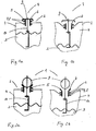
- FIG. 1 a shows a first embodiment of a safety valve 1 in a closed state.
- a valve body 5 with a valve seat 6 and two circumferential sealing lips 7, 8 is inserted into the tank wall.
- On the valve seat 6 is a flat valve plate 9, which is held in the tank 4 via a holding device 10.
- the valve disk 9 seals the tank 4 against the valve seat 6.
- the valve plate 9 in the case of a limited spatially displaceable embodiment can only rest on the valve seat 6 by its own weight or, in the case of a fixed embodiment, be firmly anchored by the holding device 10.
- FIG. 1b shows the safety valve 1 in an open state.
- emptying the slurry 3, for example during a working trip, and in the absence of a (fully) functioning or open pressure compensation device creates a negative pressure in the slurry tank 4.
- the tank wall at the top of the tank 2 has deformed concave.
- the valve seat 6 is separated from the valve disk 9, which is fixed in place or has a limited space. Air flows into the Kunststoffgülletank 4, whereby the negative pressure is compensated.
- FIG. 2a 2b shows a second embodiment of a safety valve 1 in a closed or opened state.
- a valve body 5 On a tank top 2 of a slurry tank 3 filled with slurry 3 is a valve body 5 with a valve seat 6 and two circumferential sealing lips 7, 8 introduced into the tank wall.
- a spherical valve plate 9 On the funnel-shaped seat surface of the valve seat 6 is a spherical valve plate 9, which is held in the tank 4 via a holding device 10.
- the spherical valve disk 9 seals the tank against the valve seat 6.
- the valve disk 9 can rest in the case of a limited spatially displaceable embodiment only by its own weight on the seat surface of the valve seat 6 or be firmly anchored in the case of a stationary embodiment by the holding device 10.
- the tank volume is reduced, causing the tank wall at the top of the tank 2 is concave deformed.
- the valve seat 6 is separated from the valve disk 9, which is fixed in place or has a limited space. Air may flow into the plastic slurry tank 4, thereby equalizing the negative pressure.
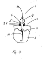
- FIG. 3 shows a third embodiment of a safety valve 1 in an open state.
- a valve body 5 with a valve seat 6 and two circumferential sealing lips 7, 8 is inserted into the tank wall.
- a spherical valve plate 9 On the funnel-shaped seat surface of the valve seat 6 is a spherical valve plate 9, which is held in the tank 4 via a holding device 10.
- the round valve disk 9 is spring-loaded by a spring device 11 in the direction of the valve seat 6.
- valve seat is separated from the valve disk in the case of a building ducking and concomitant concave deformation of the tank wall.
- valve disk supported by the locally displaceable holding device is pressed upward after overcoming the spring force of the spring device 9 until, finally, the valve disk 9 is separated from the valve seat 6.
- the safety valve according to the invention is particularly suitable as an additional safety device to prevent pressure damage to pressure-sensitive plastic tanks, in particular Kunststoffgülletanks.
- the valve is inexpensive, can also be installed later in already finished tanks and works reliably over the entire life of the tanks.
Landscapes
- Engineering & Computer Science (AREA)
- General Engineering & Computer Science (AREA)
- Mechanical Engineering (AREA)
- Treatment Of Sludge (AREA)
- Cooling, Air Intake And Gas Exhaust, And Fuel Tank Arrangements In Propulsion Units (AREA)
Description
- Die Erfindung betrifft ein Sicherheitsventil für einen Kunststofftank, insbesondere einen Kunststoffgülletank, mit einem an einer Tankoberseite ausgebildeten Ventilkörper mit einem Ventilsitz und einem Ventilteller, der den Tank gegen den Ventilsitz abdichtet.
- Es existieren grundsätzlich verschieden Arten einen Gülletank zu befüllen. So kann gemäß der
WO 2006/64701 A1 - Eine weitere Art einen Gülletank zu befüllen ist eine Fremdbefüllung über einen Einfülldom. Dabei wird mit Hilfe, beispielsweise einer Tauchschneidpumpe, die Gülle aus einem Güllevorratsbehälter, beispielsweise einer Güllegrube, in den Tank gepumpt. Ferner kann auch bei sog. Pumptankwagen, die in der Regel über leichte Kunststofftanks verfügen, der Tank über eine am Tankwagen angeordnete Verdrängerpumpe befüllt werden. Die beiden letztgenannten Arten einer Befüllung sind sowohl für druckstabile Tanks, insbesondere Stahltanks, wie auch für druckempfindliche Tanks, insbesondere Kunststofftanks geeignet.
- Werden druckempfindliche Kunststofftanks befüllt ist stets darauf zu achten, dass sich weder ein Über- noch ein Unterdruck in dem Tank aufbaut, da diese Drücke Schäden, insbesondere Brüche oder Risse in der Tankwand verursachen.
- Zur Vermeidung eines Unterdrucks, insbesondere bei Entleeren des Tanks kann beispielsweise ein Einfüllschieber geöffnet werden. Dies hat jedoch den Nachteil, dass beim Ausbringen der Gülle auf bergigem Gelände oder beim Bremsen des Tankwagens Gülle durch die Öffnung, d.h. den Einfüllschieber, verspritzen kann. Es ist daher üblich einen Druckausgleich für einen druckempfindlichen Kunststofftank über einen an der Tankoberseite angeordneten Überlaufschlauch zu bewerkstelligen. Ein derartiger Überlaufschlauch ist mit einer Tanköffnung an der Tankoberseite verbunden und verläuft zunächst senkrecht nach oben, um dann in einem Bogen nach unten zu zeigen. So wird zumindest ein Verspritzen der Gülle beim Bremsen oder bei Bergfahrten vermieden. Der Schlauch kann ferner durch ein Ventil verschlossen werden, um bei Transportfahrten eine Straßenverschmutzung zu vermeiden. Bei Arbeitsfahrten, d.h. beim Ausbringen der Gülle auf einen zu düngenden Boden, wie auch beim Befüllen des Tanks muss das Ventil jedoch geöffnet sein, um einen Druckausgleich zu gewährleisten.
- Für den Fall, dass eine Bedienperson vergisst nach einer Transportfahrt bzw. vor einer Arbeitsfahrt das Ventil des Überlaufschlauchs zu öffnen, oder aber sollte der Schlauch stark verschmutzt oder zugefroren sein, ist ein Druckausgleich für den Kunststofftank nicht oder zumindest nicht in dem nötigen Umfang gewährleistet, und es kann zu Schäden, insbesondere Rissen, am Tank kommen.
- Aus der gattungsgemäßen
US 5 803 115 A ist ein Sicherheitsventil zur Über- und Unterdruckentlastung eines unter Druck setzbaren Behälters bekannt, wobei das Ventil einen am Tank dichtend befestigbaren Ventilkörper, einen länglichen Stab mit einem Federsitz darauf, und ein Abdeckelement zur axialen Bewegung mit der Stange umfasst. Der Aufbau dieses als Kombinationsventil ausgebildeten Sicherheitsventils ist jedoch für eine Anwendung im landwirtschaftlichen Bereich zu komplex. - Aufgabe der vorliegenden Erfindung ist es ein Sicherheitsventil für einen Kunststofftank, insbesondere einen Kunststoffgülletank, bereitzustellen, das neben den Druckausgleichseinrichtungen gemäß dem Stand der Technik eine zusätzliche Einrichtung zum Schutz des Tanks vor Druckunterschieden, insbesondere vor einem Unterdruck darstellt.
- Diese Aufgabe wird von einem Sicherheitsventil mit den Merkmalen des Anspruchs 1 gelöst. Durch die Merkmale der abhängigen Ansprüche wird die Erfindung in vorteilhafterweise noch weiter ausgestaltet.
- Die Erfindung geht von dem allgemeinen Gedanken aus, die Elastizität eines Kunststofftanks, insbesondere eines Kunstoffgülletanks in vorteilhafterweise auszunützen. Durch einen an einer Tankoberseite ausgebildeten Ventilkörper mit einem Ventilsitz und einem Ventilteller, der den Tank gegen den Ventilsitz abdichtet, wobei der Ventilteller über eine Halteeinrichtung im Tank gehaltert ist, wird das erfindungsgemäße Ventil geöffnet sobald sich das Tankvolumen infolge eines Unterdrucks verringert.
- In der Regel wird sich in Folge eines Unterdrucks nämlich die Tankwand an der Oberseite des Gülletanks leicht konkav verformen. Diese Verformung wird erfindungsgemäß ausgenutzt um den Ventilsitz von dem Ventilteller zu trennen, so dass Luft in den Tank einströmen kann und damit ein Druckausgleich hergestellt wird.
- In einer vorteilhaften Ausführungsform des erfindungsgemäßen Sicherheitsventils ist der Ventilteller gegenüber dem Ventilsitz über eine Halteeinrichtung im Tank ortsfest gehaltert. Demnach reicht bereits eine geringfügige konkave Verformung der Tankwand um den Ventilsitz vom Ventilteller zu trennen, und damit das Ventil zu öffnen. Diese Ausführungsform eignet sich insbesondere für leichte Kunststofftanks mit dünnen Tankwänden.
- In einer weiteren vorteilhaften Ausführungsform des erfindungsgemäßen Sicherheitsventils ist der Ventilteller gegenüber dem Ventilsitz über eine Halteeinrichtung im Tank beschränkt ortsverschieblich gehaltert. Der Ventilteller ist nach oben längsverschieblich, wohingegen die Verschieblichkeit nach unten, beispielsweise durch einen Anschlag, beschränkt ist. Durch diese vertikal beschränkte Verschieblichkeit des Ventiltellers wird erfindungsgemäß der Ventilsitz durch eine konkave Verformung der Tankwand vom Ventilteller getrennt.
- Baut sich hingegen, beispielsweise beim Befüllen des Tanks ein Überdruck auf, wird der über eine Halteeinrichtung im Tank beschränkt ortsverschiebliche Ventilteller, gegebenenfalls bis zu einem oberen Anschlag, vertikal nach oben gedrückt, und das Sicherheitsventil öffnet in herkömmlicher Art und Weise wobei der Ventilteller vom Ventilsitz getrennt wird.
- Da sich beim Befüllen des Gülletanks oder bei Transportfahrten oftmals ein unschädlicher Überdruck im Tank aufbaut, ist in einer bevorzugten Weiterbildung der Ventilteller federbelastet. Dies hat den Vorteil, dass zunächst ein bestimmter Überdruck im Tank herrschen muss, bevor das Sicherheitsventil öffnet. Dabei kann der Ventilteller druckfederbelastet sein, wenn die Federeinrichtung außerhalb des Tanks angeordnet ist oder zugfederbelastet, wenn die Federeinrichtung innerhalb des Tanks angeordnet ist.
- Erfindungsgemäß ist der Ventilkörper an der Tankoberseite ausgebildet. Der Ventilkörper kann integral mit dem Tank ausgebildet, beispielsweise angespritzt oder stoffschlüssig mit der Tankwand verbunden sein. Bevorzugt ist der Ventilkörper ein, vorzugsweise elastischer Einsatz, mit zwei umlaufenden Dichtlippen, der in eine entsprechende Öffnung der Tankwand eingebracht wird. Dies hat den Vorteil, dass auch ältere Kunststofftanks über den Zubehörhandel mit einem erfindungsgemäßen Sicherheitsventil ausgestattet werden können.
- Erfindungsgemäß ist der Ventilteller über eine Halteeinrichtung im Tank gehaltert. Die Halteeinrichtung ist ein- oder mehrteilig ausgeführt und am Tankboden, oder an im Tankraum vorhandenen Querstreben oder Schwallwänden befestigt. Die Befestigung an Querstreben oder Schwallwänden hat den Vorteil, dass die Halteeinrichtung kürzer und damit materialökonomisch ausgeführt werden kann. Über die Halteeinrichtung ist der Ventilteller ortsfest oder beschränkt ortsverschieblich, insbesondere längsverschieblich gehaltert. Der Ventilteller kann beispielsweise über eine vertikal angeordnete Führungsvorrichtung zwischen zwei Anschlägen längsverschieblich gehaltert sein.
- Die Art, Größe und Ausführung des Ventiltellers ist nicht erfindungswesentlich. So kann der Ventilteller kugel- oder kegelförmig oder eben ausgebildet sein, und sollte in einer Schließstellung auf dem Ventilsitz dichtend aufliegen. Bevorzugt ist der Ventilteller ein, vorzugsweise elastischer runder Körper, beispielsweise eine Gummikugel, mit einer zentral angeordneten Bohrung oder Durchbruch zur Befestigung der Halteeinrichtung.
- Zusätzliche Einzelheiten und weitere Vorteile der Erfindung werden nachfolgend an Hand von drei Sicherheitsventilen, auf welche die vorliegende Erfindung jedoch nicht beschränkt ist, in Verbindung mit der beigefügten Zeichnung beschrieben. In den Figuren sind gleiche oder funktionsgleiche technische Merkmale mit den gleichen Bezugszeichen versehen.
- Darin zeigen schematisch:
- Fig. 1a und 1b
- eine erste Ausführungsform eines Sicherheitsventils in geschlossenem bzw. in einem aufgrund eines Unterdrucks geöffneten Zustand;
- Fig. 2b und 2b
- eine zweite Ausführungsform eines Sicherheitsventils in geschlossenem bzw. in einem aufgrund eines Unterdrucks geöffneten Zustand und
- Fig. 3
- eine dritte Ausführungsform eines Sicherheitsventils in einem aufgrund eines Überdrucks geöffneten Zustand.
-
Figur 1 a zeigt eine erste Ausführungsform eines Sicherheitsventils 1 in einem geschlossenen Zustand. Auf einer Tankoberseite 2 eines mit Gülle 3 gefüllten Gülletanks 4 ist ein Ventilkörper 5 mit einem Ventilsitz 6 und mit zwei umlaufenden Dichtlippen 7, 8 in die Tankwand eingebracht. Auf dem Ventilsitz 6 liegt ein flacher Ventilteller 9, der über eine Halteeinrichtung 10 im Tank 4 gehaltert ist. Der Ventilteller 9 dichtet den Tank 4 gegen den Ventilsitz 6 ab. Dabei kann der Ventilteller 9 im Fall einer beschränkt ortsverschieblichen Ausführungsform lediglich durch sein Eigengewicht auf dem Ventilsitz 6 aufliegen oder aber im Fall einer ortsfesten Ausführungsform durch die Halteeinrichtung 10 fest verankert sein. -
Figur 1b zeigt das Sicherheitsventil 1 in einem geöffneten Zustand. Durch das Entleeren der Gülle 3, beispielsweise während einer Arbeitsfahrt, und in Ermangelung einer (voll)funktionsfähigen bzw. geöffneten Druckausgleichseinrichtung entsteht ein Unterdruck in dem Gülletank 4. Die Tankwand an der Oberseite des Tanks 2 hat sich konkav verformt. Durch diese Verformung wird der Ventilsitz 6 von dem ortsfest oder beschränkt ortsverschieblich gehalterten Ventilteller 9 getrennt. Es strömt Luft in den Kunststoffgülletank 4 ein, wodurch der Unterdruck ausgeglichen wird. -
Figur 2a bzw. 2b zeigt eine zweite Ausführungsform eines Sicherheitsventils 1 in einem geschlossenen bzw. geöffneten Zustand. Auf einer Tankoberseite 2 eines mit Gülle 3 gefüllten Gülletanks 4 ist ein Ventilkörper 5 mit einem Ventilsitz 6 und mit zwei umlaufenden Dichtlippen 7, 8 in die Tankwand eingebracht. Auf der trichterförmigen Sitzfläche des Ventilsitzes 6 liegt ein kugelförmiger Ventilteller 9, der über eine Halteeinrichtung 10 im Tank 4 gehaltert ist. Der kugelförmige Ventilteller 9 dichtet den Tank gegen den Ventilsitz 6 ab. Dabei kann der Ventilteller 9 in Fall einer beschränkt ortsverschieblichen Ausführungsform lediglich durch sein Eigengewicht auf der Sitzfläche des Ventilsitzes 6 aufliegen oder aber im Fall einer ortsfesten Ausführungsform durch die Halteeinrichtung 10 fest verankert sein. - Durch ein Entleeren der Gülle 3 und in Ermangelung eines Druckausgleichs durch eine (voll)funktionsfähige Ausgleichseinrichtung, verringert sich das Tankvolumen, wodurch sich die Tankwand an der Oberseite des Tanks 2 konkav verformt. Durch diese Verformung wird der Ventilsitz 6 von dem ortsfest oder beschränkt ortsverschieblich gehalterten Ventilteller 9 getrennt. Es kann Luft in den Kunststoffgülletank 4 einströmen, wodurch der Unterdruck ausgeglichen wird.
-
Figur 3 zeigt eine dritte Ausführungsform eines Sicherheitsventils 1 in einem geöffneten Zustand. Auf einer Tankoberseite 2 eines mit Gülle 3 gefüllten Gülletanks 4 ist ein Ventilkörper 5 mit einem Ventilsitz 6 und mit zwei umlaufenden Dichtlippen 7, 8 in die Tankwand eingebracht. Auf der trichterförmigen Sitzfläche des Ventilsitzes 6 liegt ein kugelförmiger Ventilteller 9, der über eine Halteeinrichtung 10 im Tank 4 gehaltert ist. Der runde Ventilteller 9 ist durch eine Federeinrichtung 11 in Richtung Ventilsitz 6 druckfederbelastet. Durch eine beschränkt ortsverschiebliche Halteeinrichtung 11 des Ventiltellers 9 ist dieser, gegebenenfalls bis zu einem oberen Anschlag, noch oben längsverschieblich, wohingegen ein Verschieblichkeit nach unten blockiert ist. Dadurch wird im Falle eines sich aufbauenden Unterducks und einer damit einhergehenden konkaven Verformung der Tankwand der Ventilsitz vom Ventilteller getrennt. Im Falle eins sich aufbauenden Überdrucks wird der durch die beschränkt ortsverschiebliche Halteeinrichtung gehalterte Ventilteller nach Überwindung der Federkraft der Federeinrichtung 9 nach oben gedrückt bis schließlich der Ventilteller 9 von dem Ventilsitz 6 getrennt wird. - Das erfindungsgemäße Sicherheitsventil eignet sich insbesondere als zusätzliche Sicherheitseinrichtung zur Vermeidung von Druckschäden an druckempfindlichen Kunststofftanks, insbesondere Kunststoffgülletanks. Das Ventil ist kostengünstig, kann auch noch nachträglich in bereits fertiggestellte Tanks eingebaut werden und arbeitet zuverlässig über gesamte die Lebensdauer der Tanks.
Claims (9)
- Sicherheitsventil (1) für einen Kunststofftank, insbesondere einen Gülletank, mit einem an einer Tankoberseite (2) ausgebildeten Ventilkörper (5) mit einem Ventilsitz (6) und einem Ventilteller (9), der den Tank gegen den Ventilsitz (6) abdichtet, wobei der Ventilteller (9) über eine Halteeinrichtung (10) im Tank gehaltert ist, dadurch gekennzeichnet, dass die Halteeinrichtung (10) ein- oder mehrteilig ausgeführt ist und am Tankboden, an einer Querstrebe oder einer Schwallwand befestigt ist.
- Sicherheitsventil (1) nach Anspruch 1, dadurch gekennzeichnet, dass der Ventilteller (9) gegenüber dem Ventilsitz (6) über die Halteeinrichtung (10) ortsfest gehaltert ist.
- Sicherheitsventil nach Anspruch 1, dadurch gekennzeichnet, dass der Ventilteller (9) gegenüber dem Ventilsitz (6) über die Halteeinrichtung (10) beschränkt ortsverschieblich gehaltert ist.
- Sicherheitsventil (1) nach Anspruch 3, dadurch gekennzeichnet, dass der Ventilteller (9) federbelastet ist.
- Sicherheitsventil (1) nach Anspruch 3 oder 4, dadurch gekennzeichnet, dass die Verschieblichkeit nach unten durch einen Anschlag beschränkt ist.
- Sicherheitsventil (1) nach einem der vorstehenden Ansprüche, dadurch gekennzeichnet, dass der Ventilteller (9) kugel- oder kegelförmig oder eben ausgebildet ist und in einer Schließstellung auf dem Ventilsitz (6) aufliegt.
- Sicherheitsventil (1) nach einem der vorstehenden Ansprüche, dadurch gekennzeichnet, dass der Ventilkörper (5) als elastischer Einsatz, mit zwei umlaufenden Dichtlippen (7, 8) ausgebildet ist
- Sicherheitsventil (1) nach einem der vorstehenden Ansprüche, dadurch gekennzeichnet, dass der durch die Halteeinrichtung (10) gehalterte Ventilteller (9) bis zu einem oberen Anschlag, noch oben längsverschieblich ist, und dass eine Verschieblichkeit nach unten blockiert ist.
- Güllefass oder Selbstfahrer mit einem Sicherheitsventil (1) nach einem der vorstehenden Ansprüche.
Priority Applications (1)
| Application Number | Priority Date | Filing Date | Title |
|---|---|---|---|
| PL14152363T PL2761982T3 (pl) | 2013-01-25 | 2014-01-24 | Zawór bezpieczeństwa dla zbiornika z tworzywa sztucznego, w szczególności zbiornika z tworzywa sztucznego na gnojowicę |
Applications Claiming Priority (1)
| Application Number | Priority Date | Filing Date | Title |
|---|---|---|---|
| DE202013000718U DE202013000718U1 (de) | 2013-01-25 | 2013-01-25 | Sicherheitsventil für einen Kunststofftank, insbesondere für einen Kunststoffgülletank |
Publications (2)
| Publication Number | Publication Date |
|---|---|
| EP2761982A1 EP2761982A1 (de) | 2014-08-06 |
| EP2761982B1 true EP2761982B1 (de) | 2015-10-07 |
Family
ID=47828393
Family Applications (1)
| Application Number | Title | Priority Date | Filing Date |
|---|---|---|---|
| EP14152363.9A Active EP2761982B1 (de) | 2013-01-25 | 2014-01-24 | Sicherheitsventil für einen Kunststofftank, insbesondere einen Kunststoffgülletank |
Country Status (3)
| Country | Link |
|---|---|
| EP (1) | EP2761982B1 (de) |
| DE (1) | DE202013000718U1 (de) |
| PL (1) | PL2761982T3 (de) |
Families Citing this family (2)
| Publication number | Priority date | Publication date | Assignee | Title |
|---|---|---|---|---|
| CN110425317A (zh) * | 2019-08-22 | 2019-11-08 | 际华三五四二纺织有限公司 | 一种自动络筒机负压风机用回风风门装置 |
| CN111120634B (zh) * | 2020-02-28 | 2022-08-09 | 重庆长安汽车股份有限公司 | 一种膜片式排气塞 |
Family Cites Families (4)
| Publication number | Priority date | Publication date | Assignee | Title |
|---|---|---|---|---|
| DE1158464B (de) * | 1957-07-02 | 1963-12-05 | Leopold Quack | Membranrueckstromventil |
| GB1260040A (en) * | 1969-09-08 | 1972-01-12 | Tudor Accessories Ltd | Horticultural sprayers with improved pressure relief valves |
| US5803115A (en) * | 1997-08-26 | 1998-09-08 | Gits Manufacturing Company | Valve for relieving pressure and vacuum conditions in a tank |
| JP2006168813A (ja) | 2004-12-17 | 2006-06-29 | Nihon Tetra Pak Kk | 充填機 |
-
2013
- 2013-01-25 DE DE202013000718U patent/DE202013000718U1/de not_active Expired - Lifetime
-
2014
- 2014-01-24 PL PL14152363T patent/PL2761982T3/pl unknown
- 2014-01-24 EP EP14152363.9A patent/EP2761982B1/de active Active
Also Published As
| Publication number | Publication date |
|---|---|
| PL2761982T3 (pl) | 2016-05-31 |
| EP2761982A1 (de) | 2014-08-06 |
| DE202013000718U1 (de) | 2013-02-04 |
Similar Documents
| Publication | Publication Date | Title |
|---|---|---|
| EP2763863B1 (de) | Fahrzeug-radaufhängung mit einem hydraulischen schwingungs-dämpfer | |
| DE2946765C2 (de) | Entsperrbares Rückschlagventil | |
| DE1555435A1 (de) | Hydraulisches Fahrzeug-Bremssystem | |
| DE176442T1 (de) | Verlaengerbare anhaengerkupplung fuer strassenfahrzeuge und schienenfahrzeuge. | |
| DE2149406C3 (de) | Ventil zum Verhindern des Rückflusses | |
| DE112011105486T5 (de) | Kraftstofflanksystem | |
| DE102013005375A1 (de) | Druckmittelbehälter für eine hydraulische Kraftfahrzeugbremsanlage | |
| DE2056634C3 (de) | Luftfederung für Tandemachsen von Fahrzeugen mit Niveauregelung und Regelung der Achslastverteilung | |
| WO2020001962A1 (de) | FAHRZEUG-RADAUFHÄNGUNG MIT EINEM VERSTELLSYSTEM FÜR DEN FUßPUNKT EINER AUFBAU-TRAGFEDER | |
| DE102014207839A1 (de) | Druckmittelbehälter mit Absperrvorrichtung. | |
| EP2454134A1 (de) | Baugruppe bestehend aus einem druckmittelvorratsbehälter und einem manuell betätigbaren hauptzylinder, insbesondere für eine hydraulische kraftradbremsanlage | |
| EP2761982B1 (de) | Sicherheitsventil für einen Kunststofftank, insbesondere einen Kunststoffgülletank | |
| DE1505289C3 (de) | Vorrichtung an einem Gleiskettenfahrzeug | |
| DE102015010055A1 (de) | Hydraulikzylinder, insbesondere Nehmerzylinder für eine hydraulische Kupplungsbetätigung für Kraftfahrzeuge | |
| DE20319920U1 (de) | Entlüftungsventil | |
| EP2883733A1 (de) | Tankanlage für ein Fahrzeug | |
| DE102005043745A1 (de) | Entlüftungssystem mit Siphonentleerung | |
| WO1999028143A1 (de) | Vorrichtung zum verhindern des überfüllens eines kraftstofftankes | |
| CH686622A5 (de) | Distanzhalteanlage zum Begrenzen von extremen Abstonden von Gegenstonden sowie Strassen- oder Schienenfahrzeug mit einer solchen Distanzhalteanlage. | |
| EP2688781B1 (de) | Druckmittelbehälter für eine hydraulische kraftfahrzeugbremsanlage und verfahren zur befüllung | |
| DE102017202083A1 (de) | Schmiermittelreservoirsystem | |
| WO2021151562A1 (de) | Hydraulisch betätigbares ventil für einen hochdrucktank | |
| DE102005041437A1 (de) | Betankungswächter | |
| DE102020108821A1 (de) | Feder-Dämpfer-Einheit für ein einspuriges Kraftfahrzeug | |
| DE69918328T2 (de) | Kraftstofftankanordnung für kraftfahrzeug |
Legal Events
| Date | Code | Title | Description |
|---|---|---|---|
| PUAI | Public reference made under article 153(3) epc to a published international application that has entered the european phase |
Free format text: ORIGINAL CODE: 0009012 |
|
| 17P | Request for examination filed |
Effective date: 20140124 |
|
| AK | Designated contracting states |
Kind code of ref document: A1 Designated state(s): AL AT BE BG CH CY CZ DE DK EE ES FI FR GB GR HR HU IE IS IT LI LT LU LV MC MK MT NL NO PL PT RO RS SE SI SK SM TR |
|
| AX | Request for extension of the european patent |
Extension state: BA ME |
|
| R17P | Request for examination filed (corrected) |
Effective date: 20141210 |
|
| RBV | Designated contracting states (corrected) |
Designated state(s): AL AT BE BG CH CY CZ DE DK EE ES FI FR GB GR HR HU IE IS IT LI LT LU LV MC MK MT NL NO PL PT RO RS SE SI SK SM TR |
|
| RIC1 | Information provided on ipc code assigned before grant |
Ipc: F16K 17/164 20060101ALI20150429BHEP Ipc: F16K 17/04 20060101ALI20150429BHEP Ipc: F16K 17/12 20060101ALI20150429BHEP Ipc: A01C 23/00 20060101AFI20150429BHEP |
|
| GRAP | Despatch of communication of intention to grant a patent |
Free format text: ORIGINAL CODE: EPIDOSNIGR1 |
|
| INTG | Intention to grant announced |
Effective date: 20150622 |
|
| GRAS | Grant fee paid |
Free format text: ORIGINAL CODE: EPIDOSNIGR3 |
|
| GRAA | (expected) grant |
Free format text: ORIGINAL CODE: 0009210 |
|
| AK | Designated contracting states |
Kind code of ref document: B1 Designated state(s): AL AT BE BG CH CY CZ DE DK EE ES FI FR GB GR HR HU IE IS IT LI LT LU LV MC MK MT NL NO PL PT RO RS SE SI SK SM TR |
|
| REG | Reference to a national code |
Ref country code: GB Ref legal event code: FG4D Free format text: NOT ENGLISH |
|
| REG | Reference to a national code |
Ref country code: AT Ref legal event code: REF Ref document number: 753105 Country of ref document: AT Kind code of ref document: T Effective date: 20151015 Ref country code: CH Ref legal event code: EP |
|
| REG | Reference to a national code |
Ref country code: IE Ref legal event code: FG4D Free format text: LANGUAGE OF EP DOCUMENT: GERMAN |
|
| REG | Reference to a national code |
Ref country code: DE Ref legal event code: R096 Ref document number: 502014000127 Country of ref document: DE |
|
| REG | Reference to a national code |
Ref country code: FR Ref legal event code: PLFP Year of fee payment: 3 |
|
| REG | Reference to a national code |
Ref country code: NL Ref legal event code: MP Effective date: 20151007 |
|
| REG | Reference to a national code |
Ref country code: LT Ref legal event code: MG4D |
|
| PG25 | Lapsed in a contracting state [announced via postgrant information from national office to epo] |
Ref country code: IS Free format text: LAPSE BECAUSE OF FAILURE TO SUBMIT A TRANSLATION OF THE DESCRIPTION OR TO PAY THE FEE WITHIN THE PRESCRIBED TIME-LIMIT Effective date: 20160207 Ref country code: HR Free format text: LAPSE BECAUSE OF FAILURE TO SUBMIT A TRANSLATION OF THE DESCRIPTION OR TO PAY THE FEE WITHIN THE PRESCRIBED TIME-LIMIT Effective date: 20151007 Ref country code: ES Free format text: LAPSE BECAUSE OF FAILURE TO SUBMIT A TRANSLATION OF THE DESCRIPTION OR TO PAY THE FEE WITHIN THE PRESCRIBED TIME-LIMIT Effective date: 20151007 Ref country code: IT Free format text: LAPSE BECAUSE OF FAILURE TO SUBMIT A TRANSLATION OF THE DESCRIPTION OR TO PAY THE FEE WITHIN THE PRESCRIBED TIME-LIMIT Effective date: 20151007 Ref country code: LT Free format text: LAPSE BECAUSE OF FAILURE TO SUBMIT A TRANSLATION OF THE DESCRIPTION OR TO PAY THE FEE WITHIN THE PRESCRIBED TIME-LIMIT Effective date: 20151007 Ref country code: NL Free format text: LAPSE BECAUSE OF FAILURE TO SUBMIT A TRANSLATION OF THE DESCRIPTION OR TO PAY THE FEE WITHIN THE PRESCRIBED TIME-LIMIT Effective date: 20151007 Ref country code: NO Free format text: LAPSE BECAUSE OF FAILURE TO SUBMIT A TRANSLATION OF THE DESCRIPTION OR TO PAY THE FEE WITHIN THE PRESCRIBED TIME-LIMIT Effective date: 20160107 |
|
| PG25 | Lapsed in a contracting state [announced via postgrant information from national office to epo] |
Ref country code: SE Free format text: LAPSE BECAUSE OF FAILURE TO SUBMIT A TRANSLATION OF THE DESCRIPTION OR TO PAY THE FEE WITHIN THE PRESCRIBED TIME-LIMIT Effective date: 20151007 Ref country code: GR Free format text: LAPSE BECAUSE OF FAILURE TO SUBMIT A TRANSLATION OF THE DESCRIPTION OR TO PAY THE FEE WITHIN THE PRESCRIBED TIME-LIMIT Effective date: 20160108 Ref country code: FI Free format text: LAPSE BECAUSE OF FAILURE TO SUBMIT A TRANSLATION OF THE DESCRIPTION OR TO PAY THE FEE WITHIN THE PRESCRIBED TIME-LIMIT Effective date: 20151007 Ref country code: RS Free format text: LAPSE BECAUSE OF FAILURE TO SUBMIT A TRANSLATION OF THE DESCRIPTION OR TO PAY THE FEE WITHIN THE PRESCRIBED TIME-LIMIT Effective date: 20151007 Ref country code: PT Free format text: LAPSE BECAUSE OF FAILURE TO SUBMIT A TRANSLATION OF THE DESCRIPTION OR TO PAY THE FEE WITHIN THE PRESCRIBED TIME-LIMIT Effective date: 20160208 Ref country code: LV Free format text: LAPSE BECAUSE OF FAILURE TO SUBMIT A TRANSLATION OF THE DESCRIPTION OR TO PAY THE FEE WITHIN THE PRESCRIBED TIME-LIMIT Effective date: 20151007 |
|
| REG | Reference to a national code |
Ref country code: DE Ref legal event code: R097 Ref document number: 502014000127 Country of ref document: DE |
|
| PG25 | Lapsed in a contracting state [announced via postgrant information from national office to epo] |
Ref country code: CZ Free format text: LAPSE BECAUSE OF FAILURE TO SUBMIT A TRANSLATION OF THE DESCRIPTION OR TO PAY THE FEE WITHIN THE PRESCRIBED TIME-LIMIT Effective date: 20151007 |
|
| PLBE | No opposition filed within time limit |
Free format text: ORIGINAL CODE: 0009261 |
|
| STAA | Information on the status of an ep patent application or granted ep patent |
Free format text: STATUS: NO OPPOSITION FILED WITHIN TIME LIMIT |
|
| PG25 | Lapsed in a contracting state [announced via postgrant information from national office to epo] |
Ref country code: SK Free format text: LAPSE BECAUSE OF FAILURE TO SUBMIT A TRANSLATION OF THE DESCRIPTION OR TO PAY THE FEE WITHIN THE PRESCRIBED TIME-LIMIT Effective date: 20151007 Ref country code: EE Free format text: LAPSE BECAUSE OF FAILURE TO SUBMIT A TRANSLATION OF THE DESCRIPTION OR TO PAY THE FEE WITHIN THE PRESCRIBED TIME-LIMIT Effective date: 20151007 Ref country code: LU Free format text: LAPSE BECAUSE OF FAILURE TO SUBMIT A TRANSLATION OF THE DESCRIPTION OR TO PAY THE FEE WITHIN THE PRESCRIBED TIME-LIMIT Effective date: 20160124 Ref country code: RO Free format text: LAPSE BECAUSE OF FAILURE TO SUBMIT A TRANSLATION OF THE DESCRIPTION OR TO PAY THE FEE WITHIN THE PRESCRIBED TIME-LIMIT Effective date: 20151007 Ref country code: DK Free format text: LAPSE BECAUSE OF FAILURE TO SUBMIT A TRANSLATION OF THE DESCRIPTION OR TO PAY THE FEE WITHIN THE PRESCRIBED TIME-LIMIT Effective date: 20151007 Ref country code: SM Free format text: LAPSE BECAUSE OF FAILURE TO SUBMIT A TRANSLATION OF THE DESCRIPTION OR TO PAY THE FEE WITHIN THE PRESCRIBED TIME-LIMIT Effective date: 20151007 |
|
| 26N | No opposition filed |
Effective date: 20160708 |
|
| PG25 | Lapsed in a contracting state [announced via postgrant information from national office to epo] |
Ref country code: MC Free format text: LAPSE BECAUSE OF FAILURE TO SUBMIT A TRANSLATION OF THE DESCRIPTION OR TO PAY THE FEE WITHIN THE PRESCRIBED TIME-LIMIT Effective date: 20151007 |
|
| REG | Reference to a national code |
Ref country code: IE Ref legal event code: MM4A |
|
| PG25 | Lapsed in a contracting state [announced via postgrant information from national office to epo] |
Ref country code: SI Free format text: LAPSE BECAUSE OF FAILURE TO SUBMIT A TRANSLATION OF THE DESCRIPTION OR TO PAY THE FEE WITHIN THE PRESCRIBED TIME-LIMIT Effective date: 20151007 |
|
| REG | Reference to a national code |
Ref country code: FR Ref legal event code: PLFP Year of fee payment: 4 |
|
| PG25 | Lapsed in a contracting state [announced via postgrant information from national office to epo] |
Ref country code: IE Free format text: LAPSE BECAUSE OF NON-PAYMENT OF DUE FEES Effective date: 20160124 |
|
| PGFP | Annual fee paid to national office [announced via postgrant information from national office to epo] |
Ref country code: FR Payment date: 20170123 Year of fee payment: 4 |
|
| PGFP | Annual fee paid to national office [announced via postgrant information from national office to epo] |
Ref country code: BE Payment date: 20170124 Year of fee payment: 4 |
|
| PG25 | Lapsed in a contracting state [announced via postgrant information from national office to epo] |
Ref country code: MT Free format text: LAPSE BECAUSE OF FAILURE TO SUBMIT A TRANSLATION OF THE DESCRIPTION OR TO PAY THE FEE WITHIN THE PRESCRIBED TIME-LIMIT Effective date: 20151007 |
|
| REG | Reference to a national code |
Ref country code: CH Ref legal event code: PL |
|
| PG25 | Lapsed in a contracting state [announced via postgrant information from national office to epo] |
Ref country code: LI Free format text: LAPSE BECAUSE OF NON-PAYMENT OF DUE FEES Effective date: 20170131 Ref country code: CH Free format text: LAPSE BECAUSE OF NON-PAYMENT OF DUE FEES Effective date: 20170131 |
|
| PG25 | Lapsed in a contracting state [announced via postgrant information from national office to epo] |
Ref country code: HU Free format text: LAPSE BECAUSE OF FAILURE TO SUBMIT A TRANSLATION OF THE DESCRIPTION OR TO PAY THE FEE WITHIN THE PRESCRIBED TIME-LIMIT; INVALID AB INITIO Effective date: 20140124 Ref country code: CY Free format text: LAPSE BECAUSE OF FAILURE TO SUBMIT A TRANSLATION OF THE DESCRIPTION OR TO PAY THE FEE WITHIN THE PRESCRIBED TIME-LIMIT Effective date: 20151007 |
|
| PG25 | Lapsed in a contracting state [announced via postgrant information from national office to epo] |
Ref country code: MK Free format text: LAPSE BECAUSE OF FAILURE TO SUBMIT A TRANSLATION OF THE DESCRIPTION OR TO PAY THE FEE WITHIN THE PRESCRIBED TIME-LIMIT Effective date: 20151007 Ref country code: TR Free format text: LAPSE BECAUSE OF FAILURE TO SUBMIT A TRANSLATION OF THE DESCRIPTION OR TO PAY THE FEE WITHIN THE PRESCRIBED TIME-LIMIT Effective date: 20151007 |
|
| PG25 | Lapsed in a contracting state [announced via postgrant information from national office to epo] |
Ref country code: BG Free format text: LAPSE BECAUSE OF FAILURE TO SUBMIT A TRANSLATION OF THE DESCRIPTION OR TO PAY THE FEE WITHIN THE PRESCRIBED TIME-LIMIT Effective date: 20151007 |
|
| GBPC | Gb: european patent ceased through non-payment of renewal fee |
Effective date: 20180124 |
|
| PG25 | Lapsed in a contracting state [announced via postgrant information from national office to epo] |
Ref country code: AL Free format text: LAPSE BECAUSE OF FAILURE TO SUBMIT A TRANSLATION OF THE DESCRIPTION OR TO PAY THE FEE WITHIN THE PRESCRIBED TIME-LIMIT Effective date: 20151007 Ref country code: FR Free format text: LAPSE BECAUSE OF NON-PAYMENT OF DUE FEES Effective date: 20180131 |
|
| REG | Reference to a national code |
Ref country code: FR Ref legal event code: ST Effective date: 20180928 |
|
| REG | Reference to a national code |
Ref country code: BE Ref legal event code: MM Effective date: 20180131 |
|
| PG25 | Lapsed in a contracting state [announced via postgrant information from national office to epo] |
Ref country code: BE Free format text: LAPSE BECAUSE OF NON-PAYMENT OF DUE FEES Effective date: 20180131 Ref country code: GB Free format text: LAPSE BECAUSE OF NON-PAYMENT OF DUE FEES Effective date: 20180124 |
|
| PGFP | Annual fee paid to national office [announced via postgrant information from national office to epo] |
Ref country code: AT Payment date: 20230126 Year of fee payment: 10 |
|
| PGFP | Annual fee paid to national office [announced via postgrant information from national office to epo] |
Ref country code: DE Payment date: 20240131 Year of fee payment: 11 |
|
| PGFP | Annual fee paid to national office [announced via postgrant information from national office to epo] |
Ref country code: PL Payment date: 20240105 Year of fee payment: 11 |
|
| REG | Reference to a national code |
Ref country code: AT Ref legal event code: MM01 Ref document number: 753105 Country of ref document: AT Kind code of ref document: T Effective date: 20240124 |
|
| PG25 | Lapsed in a contracting state [announced via postgrant information from national office to epo] |
Ref country code: AT Free format text: LAPSE BECAUSE OF NON-PAYMENT OF DUE FEES Effective date: 20240124 |
|
| REG | Reference to a national code |
Ref country code: DE Ref legal event code: R082 Ref document number: 502014000127 Country of ref document: DE Representative=s name: EINSIEDLER, JOHANNES HERBERT, DIPL.-CHEM. UNIV, DE |
|
| PG25 | Lapsed in a contracting state [announced via postgrant information from national office to epo] |
Ref country code: AT Free format text: LAPSE BECAUSE OF NON-PAYMENT OF DUE FEES Effective date: 20240124 |
|
| REG | Reference to a national code |
Ref country code: DE Ref legal event code: R119 Ref document number: 502014000127 Country of ref document: DE |
|
| PG25 | Lapsed in a contracting state [announced via postgrant information from national office to epo] |
Ref country code: DE Free format text: LAPSE BECAUSE OF NON-PAYMENT OF DUE FEES Effective date: 20250801 |