EP2762038A1 - Unterputz-Regalträger zur Halterung eines Regals eines Möbelstücks und Regal mit besagter Vorrichtung - Google Patents
Unterputz-Regalträger zur Halterung eines Regals eines Möbelstücks und Regal mit besagter Vorrichtung Download PDFInfo
- Publication number
- EP2762038A1 EP2762038A1 EP14152100.5A EP14152100A EP2762038A1 EP 2762038 A1 EP2762038 A1 EP 2762038A1 EP 14152100 A EP14152100 A EP 14152100A EP 2762038 A1 EP2762038 A1 EP 2762038A1
- Authority
- EP
- European Patent Office
- Prior art keywords
- pin
- spring
- shelf
- sliding seat
- casing
- Prior art date
- Legal status (The legal status is an assumption and is not a legal conclusion. Google has not performed a legal analysis and makes no representation as to the accuracy of the status listed.)
- Granted
Links
- 230000006835 compression Effects 0.000 claims description 6
- 238000007906 compression Methods 0.000 claims description 6
- 238000000465 moulding Methods 0.000 description 6
- 230000008901 benefit Effects 0.000 description 3
- 238000012423 maintenance Methods 0.000 description 3
- 238000004519 manufacturing process Methods 0.000 description 3
- 239000000463 material Substances 0.000 description 3
- 230000009471 action Effects 0.000 description 2
- 238000010168 coupling process Methods 0.000 description 2
- 238000005859 coupling reaction Methods 0.000 description 2
- 230000004048 modification Effects 0.000 description 2
- 238000012986 modification Methods 0.000 description 2
- 230000001154 acute effect Effects 0.000 description 1
- 238000010276 construction Methods 0.000 description 1
- 230000008878 coupling Effects 0.000 description 1
- 230000006866 deterioration Effects 0.000 description 1
- 238000006073 displacement reaction Methods 0.000 description 1
- 230000005489 elastic deformation Effects 0.000 description 1
- 230000002452 interceptive effect Effects 0.000 description 1
- 230000009467 reduction Effects 0.000 description 1
- 230000001960 triggered effect Effects 0.000 description 1
Images


Classifications
-
- A—HUMAN NECESSITIES
- A47—FURNITURE; DOMESTIC ARTICLES OR APPLIANCES; COFFEE MILLS; SPICE MILLS; SUCTION CLEANERS IN GENERAL
- A47B—TABLES; DESKS; OFFICE FURNITURE; CABINETS; DRAWERS; GENERAL DETAILS OF FURNITURE
- A47B96/00—Details of cabinets, racks or shelf units not covered by a single one of groups A47B43/00 - A47B95/00; General details of furniture
- A47B96/06—Brackets or similar supporting means for cabinets, racks or shelves
- A47B96/066—Supporting means received within an edge of the shelf
-
- E—FIXED CONSTRUCTIONS
- E05—LOCKS; KEYS; WINDOW OR DOOR FITTINGS; SAFES
- E05B—LOCKS; ACCESSORIES THEREFOR; HANDCUFFS
- E05B15/00—Other details of locks; Parts for engagement by bolts of fastening devices
- E05B15/04—Spring arrangements in locks
-
- E—FIXED CONSTRUCTIONS
- E05—LOCKS; KEYS; WINDOW OR DOOR FITTINGS; SAFES
- E05C—BOLTS OR FASTENING DEVICES FOR WINGS, SPECIALLY FOR DOORS OR WINDOWS
- E05C1/00—Fastening devices with bolts moving rectilinearly
- E05C1/02—Fastening devices with bolts moving rectilinearly without latching action
- E05C1/04—Fastening devices with bolts moving rectilinearly without latching action with operating handle or equivalent member rigid with the bolt
-
- A—HUMAN NECESSITIES
- A47—FURNITURE; DOMESTIC ARTICLES OR APPLIANCES; COFFEE MILLS; SPICE MILLS; SUCTION CLEANERS IN GENERAL
- A47B—TABLES; DESKS; OFFICE FURNITURE; CABINETS; DRAWERS; GENERAL DETAILS OF FURNITURE
- A47B96/00—Details of cabinets, racks or shelf units not covered by a single one of groups A47B43/00 - A47B95/00; General details of furniture
- A47B96/06—Brackets or similar supporting means for cabinets, racks or shelves
- A47B96/068—Very short brackets, quickly attachable or detachable to a vertical support surface
Definitions
- the present invention relates to a flush-mounted shelf support for supporting a shelf of a piece of furniture, such as for example a wooden shelf.
- Shelf supports are known for supporting shelves in a piece of furniture which devices are configured to be inserted into suitable seats provided at the lateral sidewalls of the shelves.
- Such shelf supports are provided with respective pins elastically projecting from the side walls of the shelves in order to be inserted into corresponding holes formed in vertical walls of the piece of furniture.
- shelf supports are of the so-called “flush-mounted” type, in the sense that they are provided with construction features capable of allowing the pin to maintain two positions:
- a first device of known type described in EP 1228721 comprises:
- the structure of the aforementioned supports of known type which - due to cost and weight reasons - are substantially entirely made of plastic materials (except, in some cases, for the pin or parts thereof) is quite complicated to be manufactured by moulding since it is necessary to provide complex and costly moulds which also require considerable costs for the maintenance of the moulding equipment.
- shelf supports are therefore not fully satisfactory from this point of view given that the market requires that such supports should have a cost as low as possible.
- the support in order to be adaptable to shelves having a low thickness, should have a size as low as possible, a requirement which prevents the achievement of elastic fins and protrusions provided with the desired requirements of robustness and of both wear resistance and breakage resistance consequent to the friction between parts caused by repeated operations on the device.
- the Applicant perceived the possibility of at least partially overcoming the aforementioned drawbacks and, more in detail, the possibility of providing a flush-mounted shelf support for supporting a shelf of a piece of furniture that is particularly reliable, robust, inexpensive and easy to drive and having at the same time improved characteristics of robustness and wear resistance and breakage resistance consequent to repeated operations on the parts constituting the device and, this, by intervening on the configuration and on the positioning of the elements for unstably holding the pin in the non-operative position by making these elements no longer directly acting on the pin but by making them acting on the spring exerting an axial thrust on the pin.
- the present invention relates to a flush-mounted shelf support for supporting a shelf of a piece of furniture, said support being configured to be housed at a lateral sidewall of the shelf and comprising:
- the shelf support of the present invention is robust and extremely reliable, without any noticeable deterioration of performance over time.
- the configuration and position of the elements configured to unstably hold the pin in the non-operative position which elements are in this case constituted by the distal portion of the sliding seat of the spring, allow to avoid the use of protrusions employed in the prior art and which should be obtained in an accurate manner so as to have accurate calibrated interferences but which are also inevitably subjected to a rapid wear and to a frequent breakage, in particular in case of repeated assembling and disassembling operations of the shelves.
- the shelf support of the present invention and in particular its containment casing may be advantageously obtained by moulding a plastic material, using a mould and a moulding equipment having production, operating and maintenance costs lower than those used for the shelf supports of the prior art.
- the shelf support of the present invention has the advantage of having a greater compactness with respect to the supports of the prior art.
- the sliding seat of the pin in fact, may have a length smaller than the length of the supports of the prior art, given that the spring is no longer housed rearwardly and coaxially to the pin, but it is housed in a suitable sliding seat structurally distinct from and positioned alongside the sliding seat of the pin.
- shelf support of the present invention has the advantage of being extremely easy and comfortable to drive.
- the aforementioned spring acting on the pin is a torsion spring.
- the torsion spring allows to exert an adequate axial thrust force on the pin even though the spring has a reduced size and a low cost related to the limited use of material.
- the torsion spring is associated to a support element laterally projecting from the pin and extending at least in part in the sliding seat of the spring.
- a guiding and sliding channel of the support element of the torsion spring is formed between the sliding seat of the pin and the sliding seat of the spring.
- the torsion spring comprises a central portion formed by a spirally wound wire and associated to the aforementioned support element.
- the torsion spring comprises a pair of arms, preferably substantially coplanar with each other, extending from said central portion.
- each arm comprises a substantially rectilinear main portion connected via an intermediate connecting portion to a substantially rectilinear free end portion inclined with respect to the main portion.
- each free end portion of the arms of the spring constitutes a sliding shoe which facilitates the displacement of the spring in the distal portion of the respective sliding seat reducing the frictions and eliminating the risk of any sticking of the arms against the sidewalls of the sliding seat which may hamper or prevent a correct projection of the pin out of the front wall of the containment casing of the support.
- the sliding seat of the spring comprises a portion of the sliding seat of the spring proximal to the front wall of the containment casing and configured to cooperate with the spring to allow the spring to exert an axial thrust on the pin.
- the proximal portion of the sliding seat of the spring comprises opposite side walls axially diverging towards the front wall of the casing and cooperating with the arms of the spring to allow the arms to form with each other a rest angle of predetermined value in said operative position of the pin.
- the distal portion of the sliding seat of the spring comprises opposite side walls cooperating with the arms of the spring to move closer and hold close the aforementioned arms with each other, so that the arms form with each other a compression angle smaller than the aforementioned rest angle.
- the opposite side walls of the distal portion of the sliding seat of the spring and the opposite side walls of the proximal portion of the sliding seat of the spring are connected with each other via respective sharp edges or respective substantially curvilinear connecting portions.
- this configuration of the opposite side walls of the sliding seat of the spring allows to define as required the line or area where the release of the elastic energy stored in the spring is triggered to perform the axial thrust action on the pin.
- the connecting line or area between the opposite side walls of the distal portion and of the proximal portion of the sliding seat of the spring is defined in a part of the aforementioned seat configured to cause the release of the elastic energy of the spring when the pin is still completely housed in the containment casing of the support.
- the opposite side walls of the distal portion of the sliding seat of the spring are substantially parallel to each other or are axially diverging at a side opposite to the aforementioned proximal portion of the sliding seat of the spring.
- the spring advantageously exerts a thrust on the pin in the direction opposite to the projection direction of the pin from the seat itself (operative position of the pin) thereby more efficiently holding the pin in its non-operative position and increasing the amount of force required to cause the projection of the pin.
- the pin comprises a respective driving element laterally projecting therefrom and slidably mounted in a respective guiding and sliding groove formed in the containment casing.
- the driving element is operable from the outside of the casing to allow a driving of the pin.
- the driving element is advantageously operated from the outside of the casing in a manual manner.
- the driving element is associated to a drive plate slidable on the containment casing.
- the drive plate substantially forms a closing cover of the aforementioned guiding and sliding groove of the driving element.
- the driving element is removably associated to the drive plate, preferably by means of a snap coupling.
- the shelf support further comprises at least one stop element configured to hold the pin in the operative position.
- the aforementioned at least one stop element cooperates in abutting relationship with the driving element of the pin.
- the aforementioned at least one stop element comprises at least one shoulder formed in the guiding and sliding groove of the driving element of the pin at an end of the groove proximal to the front wall of the containment casing.
- the present invention relates to a shelf of a piece of furniture comprising at least one shelf support of the aforementioned type.
- the advantageous features of the shelf support according to the present invention outlined above lead to an equal number of advantageous features of the shelf of a piece of furniture comprising such a support, such as for example a reduction of production costs and an increase of operating reliability.
- a flush-mounted shelf support according to the invention for supporting a shelf 12 of a piece of furniture is generally indicated at 10.
- the shelf support 10 is configured to be housed at a lateral sidewall 12a of the shelf 12, in a corresponding seat 12b which is generally open towards the lateral sidewall 12a and towards a bottom wall 12c of the shelf 12 (in figure 1 the shelf is shown upside down, so as to better illustrate the shelf support 10).
- the shelf support 10 comprises a containment casing 14 and a pin 16 axially mounted in a sliding manner in a respective sliding seat 18 formed in the casing 14.
- the pin 16 is provided with lightening grooves 17.
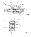
- the pin 16 is axially slidable between an operative position ( figures 1 , 5 , 6 and 7 ), in which the pin 16 at least partially projects from a front wall 14a of the casing 14 and out of the lateral sidewall 12a of the shelf 12, and a non-operative position ( figure 4 ), in which the pin 16 is retracted in the seat 18 so as to not project from the front wall 14a of the casing 14 and, when the support is mounted in the shelf 12, from the lateral sidewall 12a of the shelf 12.
- the operative position of the pin 16 allows the shelf 12 to be supported in the piece of furniture, while the non-operative position of the pin 16 allows to disassemble the shelf.
- a spring 20 is active on the pin 16 to push the latter towards the operative position.
- the spring 20 is configured to exert an axial thrust on the pin 16.
- the spring 20 is a torsion spring.
- the spring 20 is housed in a respective sliding seat 22 which is structurally distinct from and positioned alongside the sliding seat 18 of the pin 16.
- the seat 22 is positioned alongside the seat 18 at a side opposite to a lateral surface 32 of the casing 14 extending substantially flush with the bottom wall 12c of the shelf 12 in the assembled configuration of the device 10 (see figure 2 ).
- the sliding seat 22 of the spring 20 comprises a portion 22a axially distal with respect to the front wall 14a of the casing 14 and configured to cooperate with the spring 20 to prevent the spring 20 from exerting an axial thrust on the pin 16.
- the distal portion 22a constitutes a holding element configured to unstably hold the pin 16 in the non-operative position (as shown in figure 4 ).
- the sliding seat 22 of the spring 20 preferably comprises a portion 22b axially proximal to the front wall 14a of the casing 14 and configured to cooperate with the spring 20 and to allow the latter to exert an axial thrust on the pin 16, until the pin reaches its operative position (as shown in figure 5 ).
- the spring 20 is associated to a support element 16a laterally projecting from the pin 16 and at least partially extending in the sliding seat 22 of the spring 20.
- a guiding and sliding channel 24 of the support element 16a of the spring 20 is formed between the sliding seat 18 of the pin 16 and the sliding seat 22 of the spring 20.
- a driving element 26 laterally projects from the pin 16 and slides in a respective guiding and sliding groove 28 formed in the casing 14.
- the driving element 26 is operable from the outside of the casing 14 to allow an operation of the pin 16, preferably to and from the non-operative position.
- the driving element 26 is associated to a drive plate 30, which can be easily operated in a manual manner.
- the plate 30 is slidably mounted on the casing 14. Still more preferably, the plate 30 slides on the lateral surface 32 of the casing 14 extending substantially flush with the bottom wall 12c of the shelf 12 in the assembled configuration of the support 10.
- the drive plate 30 substantially forms a cover for closing the guiding and sliding groove 28 of the driving element 26.
- the driving element 26 is removably associated to the drive plate 30. More preferably, a snap-coupling of a free end 26a of the driving element 26 in a corresponding housing seat 30a formed in the drive plate 30 is provided.
- the seat 30a is formed between a pair of flexible walls 30b, extending from the plate 30 towards the free end 26a of the driving element 26 in the assembled configuration of the support 10 ( figure 6 ).
- the seat 30a is also advantageously provided with a slot 30d accessible from the outside to allow, if desired, a driving of the plate 30 by means of the tip of a screwdriver (see figure 2 ).
- the shelf support 10 further comprises a stop element 34 configured to hold the pin 16 in the operative position, preventing the pin 16 from being completely pushed out of its sliding seat 18.
- the stop element 34 cooperates in abutment relationship with the driving element 26.
- the stop element 34 preferably comprises at least one shoulder and, still more preferably, a pair of shoulders 35 formed at an end of the guiding and sliding groove 28 of the driving element 26 proximal to the front wall 14a of the casing 14. More preferably, the shoulders 35 are formed by a pair of teeth substantially shaped in a herringbone pattern, directed towards the inner part of the groove 28.
- the inclination and the size of the teeth allow the passage of the driving element 26 (by way of an elastic deformation thereof), when the device 10 is assembled by pushing the pin 16 in its seat 18. Afterwards, the inner edge of the teeth forms a stop element against which a front edge of the driving element 26 (shown with dashed lines in figure 7 ) abuts, so as to prevent the projection of the pin 16 beyond its operative position.
- the spring 20 preferably comprises a central portion 20a formed by a spirally wound wire 20b.
- the spring 20 is externally associated to the support element 16a by means of the central portion 20a, in which the support element 16a (for example constituted by a peg, as shown in figures 2 and 4-6 ) is inserted.
- the spring 20 comprises a pair of arms 20c substantially coplanar with each other and extending from the central portion 20a.
- the arms 20c are constituted by an extension of the wire 20b forming the central portion 20a of the spring 20, as conventionally known for torsion springs.
- each arm 20c comprises a substantially rectilinear main portion 20d connected - via an intermediate connecting portion 20e - to a substantially rectilinear free end portion 20f preferably inclined with respect to the main portion 20d.
- the intermediate connecting portion 20e is substantially curvilinear.
- the distal portion 22a of the sliding seat 22 of the spring 20 comprises opposite side walls 23a cooperating with the arms 20c to move closer and hold close to each other the arms 20c, so that the arms 20c form with each other a compression angle (as shown in figure 4 ).
- the arms 20c of the spring 20 are arranged on a side of the central portion 20a facing the front wall 14a of the casing 14.
- the opposite side walls 23a of the distal portion 22a of the seat 22 are substantially parallel to each other ( figures 4 and 5 ) and are also preferably substantially parallel to a longitudinal centreline plane of the casing 14 and of the seat 22, indicated at X-X in figures 4 and 5 .
- the opposite side walls 23a may be axially diverging at a side opposite to the proximal portion 22b of the seat 22.
- the proximal portion 22b of the sliding seat 22 of the spring 20 comprises opposite side walls 23b cooperating with the arms 20c, preferably with the substantially curvilinear intermediate connecting portion 20e, to allow the arms 20c to form with each other a rest angle having a predetermined value in the operative position of the pin 16 (shown in figure 5 ).
- the opposite side walls 23b are axially diverging (with respect to the axis of symmetry of the seat 22) towards the front wall 14a of the casing 14 so as to allow the arms 20c to slide on the opposite side walls 23b until the arms 20c form the rest angle with each other.
- the opposite side walls 23b of the proximal portion 22b are arranged according to an angle which can be lower than or substantially equal to said rest angle of the arms 20c of the spring 20 and which is greater than said compression angle of the arms 20c of the spring 20.
- the expression rest angle is used to indicate the maximum angle of opening formed by the arms 20c of the spring 20 with each other within the seat 22 of the spring 20 (see figure 5 ). Such an angle may be equal to or lower than the angle of complete release of the elastic energy of the torsion spring 20, which angle corresponds to the angle between the arms 20c of the spring 20 when the latter is completely extracted from the seat 22.
- the rest angle formed with each other by the arms 20c of the spring 20 - or rather by their main portion 20d - is comprised between 60° and 180°, more preferably between 60° and 120° and, still more preferably, between 80 and 100°.
- the compression angle formed with each other by the arms 20c of the spring 20 - or rather by their main portion 20d - is comprised between 10° and 50° and, more preferably, between 30° and 45°.
- the opposite side walls 23a of the distal axial portion 22a of the sliding seat 22 of the spring 20 and the opposite side walls 23b of the proximal axial portion 22b are connected with each other via respective sharp edges 23c.
- the side walls 23a and the side walls 23b may be connected with each other via respective substantially curvilinear connecting portions.
- the support operates as follows.
- a first operating step adapted to allow the assembling of the shelf 12 within a piece of furniture, it is required to "cock" the support 10, i.e. to displace the pin 16 in its non-operative position.
- Such operation is manually carried out by moving the driving element 26 (in the preferred embodiment illustrated by operating on the plate 30 associated to the driving element) so as to move the spring 20 in the distal portion 22a of the sliding seat 22 of the spring 20 overcoming the resistance exerted by the arms 20c of the spring.
- the spring 20 is "cocked", i.e. the arms 20c of the spring 20 are forced to move close to each other by the side walls 23a of the distal axial portion 22a and they are "loaded” with elastic energy.
- the pin 16 In a subsequent operating step, adapted to allow the shelf 12 to be supported within the piece of furniture, the pin 16 should be displaced in its operative position by moving the driving element 26 (preferably by acting on the plate 30 associated thereto) towards the front wall 14a of the casing 14.
- the arms 20c of the spring 20 pass beyond the sharp edges 23c, or the substantially curvilinear connecting portions, and enter in the proximal axial portion 22b of the seat 22, the arms 20c are "released” moving away from each other and releasing the elastic energy previously loaded and causing the axial sliding of the pin 16 in its sliding seat 18 towards the front wall 14a of the casing 14 up to the operative position of the pin 16.
- the substantially curvilinear intermediate connecting portions 20e and the free end portions 20f of the arms 20c (which form with each other an angle smaller than the angle formed by the two main portions 20d of the arms 20c) advantageously constitute as many slides which facilitate the movement of the spring 20 in the distal portion 22a of the seat 22 by reducing friction and eliminating the risk of a possible sticking of the arms 20c against the side walls 23a of the distal portion 22a which may hamper or prevent the correct projection of the pin 16.
- the pin 16 is moved back in its non-operative position by operating again on the driving element 26 (preferably by acting on the plate 30 associated thereto) so as to move the spring 20 in the distal axial portion 22a of the sliding seat 22 thereof and "cock" again the support 10.
- the spring 20 exerts a thrust on the pin 16 in a direction opposite to the projection direction of the pin 16 from the seat 18 (operative position of the pin 16) thereby more efficiently holding the pin 16 in its non-operative position and increasing the amount of force required to cause the projection of the pin 16.
Landscapes
- Engineering & Computer Science (AREA)
- Mechanical Engineering (AREA)
- Chairs For Special Purposes, Such As Reclining Chairs (AREA)
- Cephalosporin Compounds (AREA)
Priority Applications (1)
| Application Number | Priority Date | Filing Date | Title |
|---|---|---|---|
| SI201430010T SI2762038T1 (sl) | 2013-01-22 | 2014-01-22 | Poravnano nameščen nosilec police za nošenje police kosa pohištva in polica kosa pohištva, ki obsega omenjeni nosilec |
Applications Claiming Priority (1)
| Application Number | Priority Date | Filing Date | Title |
|---|---|---|---|
| IT000076A ITMI20130076A1 (it) | 2013-01-22 | 2013-01-22 | Dispositivo reggipiano a scomparsa per supportare un ripiano di un mobile e ripiano di mobile comprendente tale dispositivo |
Publications (2)
| Publication Number | Publication Date |
|---|---|
| EP2762038A1 true EP2762038A1 (de) | 2014-08-06 |
| EP2762038B1 EP2762038B1 (de) | 2015-09-30 |
Family
ID=47997661
Family Applications (1)
| Application Number | Title | Priority Date | Filing Date |
|---|---|---|---|
| EP14152100.5A Not-in-force EP2762038B1 (de) | 2013-01-22 | 2014-01-22 | Einbau-Regalträger zur Halterung eines Regals eines Möbelstücks und Regal eines Möbelstuckes mit besagtem Träger |
Country Status (4)
| Country | Link |
|---|---|
| EP (1) | EP2762038B1 (de) |
| ES (1) | ES2559836T3 (de) |
| IT (1) | ITMI20130076A1 (de) |
| SI (1) | SI2762038T1 (de) |
Cited By (4)
| Publication number | Priority date | Publication date | Assignee | Title |
|---|---|---|---|---|
| WO2017076467A1 (en) * | 2015-11-06 | 2017-05-11 | Arcelik Anonim Sirketi | Refrigerator having a stowable shelf holder |
| JP2017192506A (ja) * | 2016-04-19 | 2017-10-26 | 小島工芸株式会社 | 棚家具及び棚部材 |
| CN109008350A (zh) * | 2018-09-05 | 2018-12-18 | 杭州顾家定制家居有限公司 | 一种橱柜滑销式层板托 |
| CN114391068A (zh) * | 2019-09-16 | 2022-04-22 | 莱昂纳多有限公司 | 用于家具搁板的完善的支撑装置 |
Citations (3)
| Publication number | Priority date | Publication date | Assignee | Title |
|---|---|---|---|---|
| EP1228721A1 (de) | 2001-02-05 | 2002-08-07 | Ferramenta Livenza S.r.l. | Regalbodenstütze für eine schnelle Montage, für Möbel und dergleichen |
| US20040155163A1 (en) * | 2003-02-12 | 2004-08-12 | Agostino Ferrari S.P.A. | Disappearing device for shelf support in furniture |
| EP2177129A1 (de) * | 2008-10-14 | 2010-04-21 | Ferramenta Livenza S.r.l. | Verbesserte Befestigungsvorrichtung für Möbelregalbretter |
-
2013
- 2013-01-22 IT IT000076A patent/ITMI20130076A1/it unknown
-
2014
- 2014-01-22 SI SI201430010T patent/SI2762038T1/sl unknown
- 2014-01-22 EP EP14152100.5A patent/EP2762038B1/de not_active Not-in-force
- 2014-01-22 ES ES14152100.5T patent/ES2559836T3/es active Active
Patent Citations (4)
| Publication number | Priority date | Publication date | Assignee | Title |
|---|---|---|---|---|
| EP1228721A1 (de) | 2001-02-05 | 2002-08-07 | Ferramenta Livenza S.r.l. | Regalbodenstütze für eine schnelle Montage, für Möbel und dergleichen |
| US20040155163A1 (en) * | 2003-02-12 | 2004-08-12 | Agostino Ferrari S.P.A. | Disappearing device for shelf support in furniture |
| EP1454565A1 (de) | 2003-02-12 | 2004-09-08 | Agostino Ferrari S.p.A. | Eine verschwindende Vorrichtung für eine Möbelregalbodenstütze |
| EP2177129A1 (de) * | 2008-10-14 | 2010-04-21 | Ferramenta Livenza S.r.l. | Verbesserte Befestigungsvorrichtung für Möbelregalbretter |
Cited By (5)
| Publication number | Priority date | Publication date | Assignee | Title |
|---|---|---|---|---|
| WO2017076467A1 (en) * | 2015-11-06 | 2017-05-11 | Arcelik Anonim Sirketi | Refrigerator having a stowable shelf holder |
| JP2017192506A (ja) * | 2016-04-19 | 2017-10-26 | 小島工芸株式会社 | 棚家具及び棚部材 |
| CN109008350A (zh) * | 2018-09-05 | 2018-12-18 | 杭州顾家定制家居有限公司 | 一种橱柜滑销式层板托 |
| CN114391068A (zh) * | 2019-09-16 | 2022-04-22 | 莱昂纳多有限公司 | 用于家具搁板的完善的支撑装置 |
| CN114391068B (zh) * | 2019-09-16 | 2024-06-04 | 莱昂纳多有限公司 | 用于家具搁板的完善的支撑装置 |
Also Published As
| Publication number | Publication date |
|---|---|
| EP2762038B1 (de) | 2015-09-30 |
| ES2559836T3 (es) | 2016-02-16 |
| ITMI20130076A1 (it) | 2014-07-23 |
| SI2762038T1 (sl) | 2016-03-31 |
Similar Documents
| Publication | Publication Date | Title |
|---|---|---|
| EP3387952B1 (de) | Gleitschienenanordnung | |
| EP2762038B1 (de) | Einbau-Regalträger zur Halterung eines Regals eines Möbelstücks und Regal eines Möbelstuckes mit besagtem Träger | |
| EP3157312B1 (de) | Gleitschienenanordnung und schienenkit dafür | |
| CN100556338C (zh) | 阻尼移动机构及包括该机构的滑动装置 | |
| US8511763B2 (en) | Self-closing device for a drawer or for a moveable part of a piece of furniture | |
| EP3143901B1 (de) | Ausziehführung | |
| US7644849B2 (en) | Effort-saving stapler | |
| EP2567635A1 (de) | Schubladenvorrichtung und schubladen-hauptkörper damit | |
| US8276799B2 (en) | Front-depression stapling device | |
| JP4704861B2 (ja) | 引出側板 | |
| US6997529B1 (en) | Synchronizing device for a tri-sector slide | |
| EP3387950A1 (de) | Gleitschienenanordnung | |
| MXPA02010717A (es) | Guia de deslizamiento de cierre automatica y mecanismo para la misma. | |
| US9878753B2 (en) | Control unit for height adjustment of a bicycle seat post | |
| CN101384193B (zh) | 自动移动机构及包括该机构的滑动装置 | |
| US20100299938A1 (en) | Pruning Hook with Hidden Driving Mechanism | |
| EP3563723B1 (de) | Gleitschienenanordnung | |
| CN203334865U (zh) | 家具缓冲器和家具铰链 | |
| US20150042107A1 (en) | Latch Spring Mechanism | |
| CN115667650B (zh) | 运动控制装置 | |
| CN111031857B (zh) | 用于使家具或家用电器的可移动部件回缩到端部位置中的回缩装置 | |
| US10667607B2 (en) | Retracting mechanism for movable furniture parts | |
| TW201536489A (zh) | 用於手工具之伸縮桿 | |
| US11577374B2 (en) | Labor-saving stapler | |
| EP2371241A1 (de) | Schubladenschiene mit einer Öffnungsvorrichtung |
Legal Events
| Date | Code | Title | Description |
|---|---|---|---|
| PUAI | Public reference made under article 153(3) epc to a published international application that has entered the european phase |
Free format text: ORIGINAL CODE: 0009012 |
|
| 17P | Request for examination filed |
Effective date: 20140122 |
|
| AK | Designated contracting states |
Kind code of ref document: A1 Designated state(s): AL AT BE BG CH CY CZ DE DK EE ES FI FR GB GR HR HU IE IS IT LI LT LU LV MC MK MT NL NO PL PT RO RS SE SI SK SM TR |
|
| AX | Request for extension of the european patent |
Extension state: BA ME |
|
| R17P | Request for examination filed (corrected) |
Effective date: 20150204 |
|
| RBV | Designated contracting states (corrected) |
Designated state(s): AL AT BE BG CH CY CZ DE DK EE ES FI FR GB GR HR HU IE IS IT LI LT LU LV MC MK MT NL NO PL PT RO RS SE SI SK SM TR |
|
| GRAP | Despatch of communication of intention to grant a patent |
Free format text: ORIGINAL CODE: EPIDOSNIGR1 |
|
| INTG | Intention to grant announced |
Effective date: 20150408 |
|
| GRAS | Grant fee paid |
Free format text: ORIGINAL CODE: EPIDOSNIGR3 |
|
| GRAA | (expected) grant |
Free format text: ORIGINAL CODE: 0009210 |
|
| AK | Designated contracting states |
Kind code of ref document: B1 Designated state(s): AL AT BE BG CH CY CZ DE DK EE ES FI FR GB GR HR HU IE IS IT LI LT LU LV MC MK MT NL NO PL PT RO RS SE SI SK SM TR |
|
| REG | Reference to a national code |
Ref country code: CH Ref legal event code: EP Ref country code: GB Ref legal event code: FG4D |
|
| REG | Reference to a national code |
Ref country code: AT Ref legal event code: REF Ref document number: 751858 Country of ref document: AT Kind code of ref document: T Effective date: 20151015 |
|
| REG | Reference to a national code |
Ref country code: IE Ref legal event code: FG4D |
|
| REG | Reference to a national code |
Ref country code: DE Ref legal event code: R096 Ref document number: 602014000274 Country of ref document: DE |
|
| PG25 | Lapsed in a contracting state [announced via postgrant information from national office to epo] |
Ref country code: GR Free format text: LAPSE BECAUSE OF FAILURE TO SUBMIT A TRANSLATION OF THE DESCRIPTION OR TO PAY THE FEE WITHIN THE PRESCRIBED TIME-LIMIT Effective date: 20151231 Ref country code: LT Free format text: LAPSE BECAUSE OF FAILURE TO SUBMIT A TRANSLATION OF THE DESCRIPTION OR TO PAY THE FEE WITHIN THE PRESCRIBED TIME-LIMIT Effective date: 20150930 Ref country code: FI Free format text: LAPSE BECAUSE OF FAILURE TO SUBMIT A TRANSLATION OF THE DESCRIPTION OR TO PAY THE FEE WITHIN THE PRESCRIBED TIME-LIMIT Effective date: 20150930 Ref country code: NO Free format text: LAPSE BECAUSE OF FAILURE TO SUBMIT A TRANSLATION OF THE DESCRIPTION OR TO PAY THE FEE WITHIN THE PRESCRIBED TIME-LIMIT Effective date: 20151230 Ref country code: LV Free format text: LAPSE BECAUSE OF FAILURE TO SUBMIT A TRANSLATION OF THE DESCRIPTION OR TO PAY THE FEE WITHIN THE PRESCRIBED TIME-LIMIT Effective date: 20150930 |
|
| REG | Reference to a national code |
Ref country code: NL Ref legal event code: MP Effective date: 20150930 |
|
| REG | Reference to a national code |
Ref country code: LT Ref legal event code: MG4D |
|
| REG | Reference to a national code |
Ref country code: AT Ref legal event code: MK05 Ref document number: 751858 Country of ref document: AT Kind code of ref document: T Effective date: 20150930 |
|
| REG | Reference to a national code |
Ref country code: ES Ref legal event code: FG2A Ref document number: 2559836 Country of ref document: ES Kind code of ref document: T3 Effective date: 20160216 |
|
| PG25 | Lapsed in a contracting state [announced via postgrant information from national office to epo] |
Ref country code: RS Free format text: LAPSE BECAUSE OF FAILURE TO SUBMIT A TRANSLATION OF THE DESCRIPTION OR TO PAY THE FEE WITHIN THE PRESCRIBED TIME-LIMIT Effective date: 20150930 Ref country code: HR Free format text: LAPSE BECAUSE OF FAILURE TO SUBMIT A TRANSLATION OF THE DESCRIPTION OR TO PAY THE FEE WITHIN THE PRESCRIBED TIME-LIMIT Effective date: 20150930 Ref country code: SE Free format text: LAPSE BECAUSE OF FAILURE TO SUBMIT A TRANSLATION OF THE DESCRIPTION OR TO PAY THE FEE WITHIN THE PRESCRIBED TIME-LIMIT Effective date: 20150930 |
|
| PG25 | Lapsed in a contracting state [announced via postgrant information from national office to epo] |
Ref country code: NL Free format text: LAPSE BECAUSE OF FAILURE TO SUBMIT A TRANSLATION OF THE DESCRIPTION OR TO PAY THE FEE WITHIN THE PRESCRIBED TIME-LIMIT Effective date: 20150930 Ref country code: CZ Free format text: LAPSE BECAUSE OF FAILURE TO SUBMIT A TRANSLATION OF THE DESCRIPTION OR TO PAY THE FEE WITHIN THE PRESCRIBED TIME-LIMIT Effective date: 20150930 Ref country code: SK Free format text: LAPSE BECAUSE OF FAILURE TO SUBMIT A TRANSLATION OF THE DESCRIPTION OR TO PAY THE FEE WITHIN THE PRESCRIBED TIME-LIMIT Effective date: 20150930 Ref country code: IS Free format text: LAPSE BECAUSE OF FAILURE TO SUBMIT A TRANSLATION OF THE DESCRIPTION OR TO PAY THE FEE WITHIN THE PRESCRIBED TIME-LIMIT Effective date: 20160130 Ref country code: EE Free format text: LAPSE BECAUSE OF FAILURE TO SUBMIT A TRANSLATION OF THE DESCRIPTION OR TO PAY THE FEE WITHIN THE PRESCRIBED TIME-LIMIT Effective date: 20150930 |
|
| PG25 | Lapsed in a contracting state [announced via postgrant information from national office to epo] |
Ref country code: BE Free format text: LAPSE BECAUSE OF NON-PAYMENT OF DUE FEES Effective date: 20160131 Ref country code: AT Free format text: LAPSE BECAUSE OF FAILURE TO SUBMIT A TRANSLATION OF THE DESCRIPTION OR TO PAY THE FEE WITHIN THE PRESCRIBED TIME-LIMIT Effective date: 20150930 Ref country code: PT Free format text: LAPSE BECAUSE OF FAILURE TO SUBMIT A TRANSLATION OF THE DESCRIPTION OR TO PAY THE FEE WITHIN THE PRESCRIBED TIME-LIMIT Effective date: 20160201 Ref country code: RO Free format text: LAPSE BECAUSE OF FAILURE TO SUBMIT A TRANSLATION OF THE DESCRIPTION OR TO PAY THE FEE WITHIN THE PRESCRIBED TIME-LIMIT Effective date: 20150930 Ref country code: PL Free format text: LAPSE BECAUSE OF FAILURE TO SUBMIT A TRANSLATION OF THE DESCRIPTION OR TO PAY THE FEE WITHIN THE PRESCRIBED TIME-LIMIT Effective date: 20150930 |
|
| REG | Reference to a national code |
Ref country code: DE Ref legal event code: R097 Ref document number: 602014000274 Country of ref document: DE |
|
| REG | Reference to a national code |
Ref country code: DE Ref legal event code: R119 Ref document number: 602014000274 Country of ref document: DE |
|
| PLBE | No opposition filed within time limit |
Free format text: ORIGINAL CODE: 0009261 |
|
| STAA | Information on the status of an ep patent application or granted ep patent |
Free format text: STATUS: NO OPPOSITION FILED WITHIN TIME LIMIT |
|
| PG25 | Lapsed in a contracting state [announced via postgrant information from national office to epo] |
Ref country code: DK Free format text: LAPSE BECAUSE OF FAILURE TO SUBMIT A TRANSLATION OF THE DESCRIPTION OR TO PAY THE FEE WITHIN THE PRESCRIBED TIME-LIMIT Effective date: 20150930 Ref country code: LU Free format text: LAPSE BECAUSE OF FAILURE TO SUBMIT A TRANSLATION OF THE DESCRIPTION OR TO PAY THE FEE WITHIN THE PRESCRIBED TIME-LIMIT Effective date: 20160122 |
|
| 26N | No opposition filed |
Effective date: 20160701 |
|
| PG25 | Lapsed in a contracting state [announced via postgrant information from national office to epo] |
Ref country code: MC Free format text: LAPSE BECAUSE OF FAILURE TO SUBMIT A TRANSLATION OF THE DESCRIPTION OR TO PAY THE FEE WITHIN THE PRESCRIBED TIME-LIMIT Effective date: 20150930 |
|
| REG | Reference to a national code |
Ref country code: FR Ref legal event code: ST Effective date: 20160930 |
|
| PG25 | Lapsed in a contracting state [announced via postgrant information from national office to epo] |
Ref country code: DE Free format text: LAPSE BECAUSE OF NON-PAYMENT OF DUE FEES Effective date: 20160802 |
|
| REG | Reference to a national code |
Ref country code: IE Ref legal event code: MM4A |
|
| PG25 | Lapsed in a contracting state [announced via postgrant information from national office to epo] |
Ref country code: FR Free format text: LAPSE BECAUSE OF NON-PAYMENT OF DUE FEES Effective date: 20160201 |
|
| PG25 | Lapsed in a contracting state [announced via postgrant information from national office to epo] |
Ref country code: BE Free format text: LAPSE BECAUSE OF FAILURE TO SUBMIT A TRANSLATION OF THE DESCRIPTION OR TO PAY THE FEE WITHIN THE PRESCRIBED TIME-LIMIT Effective date: 20150930 |
|
| PG25 | Lapsed in a contracting state [announced via postgrant information from national office to epo] |
Ref country code: IE Free format text: LAPSE BECAUSE OF NON-PAYMENT OF DUE FEES Effective date: 20160122 |
|
| PG25 | Lapsed in a contracting state [announced via postgrant information from national office to epo] |
Ref country code: MT Free format text: LAPSE BECAUSE OF FAILURE TO SUBMIT A TRANSLATION OF THE DESCRIPTION OR TO PAY THE FEE WITHIN THE PRESCRIBED TIME-LIMIT Effective date: 20150930 |
|
| REG | Reference to a national code |
Ref country code: CH Ref legal event code: PL |
|
| PG25 | Lapsed in a contracting state [announced via postgrant information from national office to epo] |
Ref country code: LI Free format text: LAPSE BECAUSE OF NON-PAYMENT OF DUE FEES Effective date: 20170131 Ref country code: CH Free format text: LAPSE BECAUSE OF NON-PAYMENT OF DUE FEES Effective date: 20170131 |
|
| PG25 | Lapsed in a contracting state [announced via postgrant information from national office to epo] |
Ref country code: SM Free format text: LAPSE BECAUSE OF FAILURE TO SUBMIT A TRANSLATION OF THE DESCRIPTION OR TO PAY THE FEE WITHIN THE PRESCRIBED TIME-LIMIT Effective date: 20150930 Ref country code: CY Free format text: LAPSE BECAUSE OF FAILURE TO SUBMIT A TRANSLATION OF THE DESCRIPTION OR TO PAY THE FEE WITHIN THE PRESCRIBED TIME-LIMIT Effective date: 20150930 Ref country code: HU Free format text: LAPSE BECAUSE OF FAILURE TO SUBMIT A TRANSLATION OF THE DESCRIPTION OR TO PAY THE FEE WITHIN THE PRESCRIBED TIME-LIMIT; INVALID AB INITIO Effective date: 20140122 |
|
| PG25 | Lapsed in a contracting state [announced via postgrant information from national office to epo] |
Ref country code: MT Free format text: LAPSE BECAUSE OF FAILURE TO SUBMIT A TRANSLATION OF THE DESCRIPTION OR TO PAY THE FEE WITHIN THE PRESCRIBED TIME-LIMIT Effective date: 20160131 Ref country code: TR Free format text: LAPSE BECAUSE OF FAILURE TO SUBMIT A TRANSLATION OF THE DESCRIPTION OR TO PAY THE FEE WITHIN THE PRESCRIBED TIME-LIMIT Effective date: 20150930 Ref country code: MK Free format text: LAPSE BECAUSE OF FAILURE TO SUBMIT A TRANSLATION OF THE DESCRIPTION OR TO PAY THE FEE WITHIN THE PRESCRIBED TIME-LIMIT Effective date: 20150930 |
|
| PG25 | Lapsed in a contracting state [announced via postgrant information from national office to epo] |
Ref country code: BG Free format text: LAPSE BECAUSE OF FAILURE TO SUBMIT A TRANSLATION OF THE DESCRIPTION OR TO PAY THE FEE WITHIN THE PRESCRIBED TIME-LIMIT Effective date: 20150930 |
|
| GBPC | Gb: european patent ceased through non-payment of renewal fee |
Effective date: 20180122 |
|
| PG25 | Lapsed in a contracting state [announced via postgrant information from national office to epo] |
Ref country code: AL Free format text: LAPSE BECAUSE OF FAILURE TO SUBMIT A TRANSLATION OF THE DESCRIPTION OR TO PAY THE FEE WITHIN THE PRESCRIBED TIME-LIMIT Effective date: 20150930 |
|
| PG25 | Lapsed in a contracting state [announced via postgrant information from national office to epo] |
Ref country code: GB Free format text: LAPSE BECAUSE OF NON-PAYMENT OF DUE FEES Effective date: 20180122 |
|
| PGFP | Annual fee paid to national office [announced via postgrant information from national office to epo] |
Ref country code: IT Payment date: 20230719 Year of fee payment: 10 Ref country code: ES Payment date: 20230804 Year of fee payment: 10 |
|
| PGFP | Annual fee paid to national office [announced via postgrant information from national office to epo] |
Ref country code: SI Payment date: 20230719 Year of fee payment: 10 |
|
| PG25 | Lapsed in a contracting state [announced via postgrant information from national office to epo] |
Ref country code: SI Free format text: LAPSE BECAUSE OF NON-PAYMENT OF DUE FEES Effective date: 20240123 |
|
| PG25 | Lapsed in a contracting state [announced via postgrant information from national office to epo] |
Ref country code: SI Free format text: LAPSE BECAUSE OF NON-PAYMENT OF DUE FEES Effective date: 20240123 |
|
| REG | Reference to a national code |
Ref country code: SI Ref legal event code: KO00 Effective date: 20241001 |
|
| PG25 | Lapsed in a contracting state [announced via postgrant information from national office to epo] |
Ref country code: IT Free format text: LAPSE BECAUSE OF NON-PAYMENT OF DUE FEES Effective date: 20240122 |
|
| REG | Reference to a national code |
Ref country code: ES Ref legal event code: FD2A Effective date: 20250303 |
|
| PG25 | Lapsed in a contracting state [announced via postgrant information from national office to epo] |
Ref country code: ES Free format text: LAPSE BECAUSE OF NON-PAYMENT OF DUE FEES Effective date: 20240123 |