EP2762268A2 - Vorrichtung zur Überwachung der Lage eines Werkzeugs oder Werkzeugträgers an einer Arbeitsspindel - Google Patents
Vorrichtung zur Überwachung der Lage eines Werkzeugs oder Werkzeugträgers an einer Arbeitsspindel Download PDFInfo
- Publication number
- EP2762268A2 EP2762268A2 EP14150534.7A EP14150534A EP2762268A2 EP 2762268 A2 EP2762268 A2 EP 2762268A2 EP 14150534 A EP14150534 A EP 14150534A EP 2762268 A2 EP2762268 A2 EP 2762268A2
- Authority
- EP
- European Patent Office
- Prior art keywords
- work spindle
- stator
- channel
- channel section
- tool
- Prior art date
- Legal status (The legal status is an assumption and is not a legal conclusion. Google has not performed a legal analysis and makes no representation as to the accuracy of the status listed.)
- Granted
Links
Images



Classifications
-
- B—PERFORMING OPERATIONS; TRANSPORTING
- B23—MACHINE TOOLS; METAL-WORKING NOT OTHERWISE PROVIDED FOR
- B23Q—DETAILS, COMPONENTS, OR ACCESSORIES FOR MACHINE TOOLS, e.g. ARRANGEMENTS FOR COPYING OR CONTROLLING; MACHINE TOOLS IN GENERAL CHARACTERISED BY THE CONSTRUCTION OF PARTICULAR DETAILS OR COMPONENTS; COMBINATIONS OR ASSOCIATIONS OF METAL-WORKING MACHINES, NOT DIRECTED TO A PARTICULAR RESULT
- B23Q17/00—Arrangements for observing, indicating or measuring on machine tools
- B23Q17/002—Arrangements for observing, indicating or measuring on machine tools for indicating or measuring the holding action of work or tool holders
- B23Q17/003—Arrangements for observing, indicating or measuring on machine tools for indicating or measuring the holding action of work or tool holders by measuring a position
-
- B—PERFORMING OPERATIONS; TRANSPORTING
- B23—MACHINE TOOLS; METAL-WORKING NOT OTHERWISE PROVIDED FOR
- B23Q—DETAILS, COMPONENTS, OR ACCESSORIES FOR MACHINE TOOLS, e.g. ARRANGEMENTS FOR COPYING OR CONTROLLING; MACHINE TOOLS IN GENERAL CHARACTERISED BY THE CONSTRUCTION OF PARTICULAR DETAILS OR COMPONENTS; COMBINATIONS OR ASSOCIATIONS OF METAL-WORKING MACHINES, NOT DIRECTED TO A PARTICULAR RESULT
- B23Q17/00—Arrangements for observing, indicating or measuring on machine tools
- B23Q17/24—Arrangements for observing, indicating or measuring on machine tools using optics or electromagnetic waves
- B23Q17/2452—Arrangements for observing, indicating or measuring on machine tools using optics or electromagnetic waves for measuring features or for detecting a condition of machine parts, tools or workpieces
- B23Q17/2476—Arrangements for observing, indicating or measuring on machine tools using optics or electromagnetic waves for measuring features or for detecting a condition of machine parts, tools or workpieces of clamping devices, e.g. work or tool holders
-
- B—PERFORMING OPERATIONS; TRANSPORTING
- B23—MACHINE TOOLS; METAL-WORKING NOT OTHERWISE PROVIDED FOR
- B23Q—DETAILS, COMPONENTS, OR ACCESSORIES FOR MACHINE TOOLS, e.g. ARRANGEMENTS FOR COPYING OR CONTROLLING; MACHINE TOOLS IN GENERAL CHARACTERISED BY THE CONSTRUCTION OF PARTICULAR DETAILS OR COMPONENTS; COMBINATIONS OR ASSOCIATIONS OF METAL-WORKING MACHINES, NOT DIRECTED TO A PARTICULAR RESULT
- B23Q17/00—Arrangements for observing, indicating or measuring on machine tools
- B23Q17/24—Arrangements for observing, indicating or measuring on machine tools using optics or electromagnetic waves
- B23Q17/248—Arrangements for observing, indicating or measuring on machine tools using optics or electromagnetic waves using special electromagnetic means or methods
-
- H—ELECTRICITY
- H01—ELECTRIC ELEMENTS
- H01P—WAVEGUIDES; RESONATORS, LINES, OR OTHER DEVICES OF THE WAVEGUIDE TYPE
- H01P3/00—Waveguides; Transmission lines of the waveguide type
- H01P3/12—Hollow waveguides
Definitions
- the invention relates to a device for monitoring the position of a tool or tool carrier on a work spindle according to the preamble of claim 1.
- the clamping devices used for this purpose are usually designed in two parts modular and have mutually corresponding plan systems, which, supported by very large clamping forces, ensure a precise and rigid fit of the tools.
- the means used for this purpose e.g. Drilling and cutting emulsions, the possibility of chips adhering to the surface systems. This is to be expected in most cases, a misalignment of the tool and insufficient rigidity of the clamping. Very fine chips lead to barely noticeable misalignments, but nevertheless result in an insufficient processing result.
- a monitoring device for detecting such misfeeds is known.
- the function of this monitoring device is based on the propagation of a radar signal in a channel formed within the work spindle by a plurality of bores, which is completed in operation directly by a plan contact surface of the tool or tool carrier, wherein the end portion of the channel is formed as a cavity resonator.
- a faulty installation of the tool or tool carrier on the tool clamping device can be detected by means of a radar signal which is radiated into the channel from a transmitter arranged outside the work spindle, is reflected on the tool or tool carrier and returned to the transmitter through the channel.
- the transmitter is arranged on a stator in which the work spindle is rotatably mounted, and the radar signal is first in a channel in the stator, with which the channel in the work spindle in an angular position of the work spindle is aligned, irradiated and passes between the stator and the working spindle on the way back and forth an air gap between the stator and the work spindle.
- This air gap caused by reflection and attenuation deterioration of the quality of the measurement signal.
- the object of the invention is to improve the quality of the measuring signal in the case of the monitoring device known from the aforementioned document.
- a two-piece directionally symmetrical passive microwave coupler is arranged, of which a first part at or in one end of the channel section in the work spindle and a second part or disposed in one end of a channel section in the stator such that the two parts of the microwave coupler face each other in a predetermined angular position of the work spindle for transmitting a microwave signal across the air gap.
- the impairment of the signal quality of the measurement signal can be significantly reduced in the transition across the air gap by the arrangement of a two-part microwave coupler.
- Essential here is the directional symmetry of the transmission characteristic, since both a transmission signal, as well as a reflection signal must overcome the air gap in opposite directions as possible with low loss.
- the first part of the microwave coupler comprises a monopole antenna, which is arranged above the end of the channel section in the work spindle and electrically connected at one end to the work spindle, and the second part of the microwave coupler has a monopole antenna which is above the The End of the channel section in the stator is arranged in the same direction as the other monopole antenna and connected via a line to the measuring device.
- the channel section in the stator is in the form of a blind bore, the depth of which is preferably one quarter of the waveguide wavelength of the channel section in the stator.
- a low-loss microwave coupler can be realized by said channel sections respectively have an end portion filled by a dielectric and the inner conductor of the respective coaxial line extends by a predetermined amount in the dielectric in the end portion.
- the two parts of the microwave coupler each have an area with an enlarged cross-section of the channel sections ending at the air gap.
- a microwave coupler for the transmission of the measurement signal via a coaxial line is to arrange a coaxial line in the opposite channel sections in the work spindle and in the stator and to arrange a slot antenna connected to the respective coaxial line at the ends of both channel sections Longitudinal direction of the slot is the circumferential direction of the work spindle or the opposite surface of the stator. This also allows a low-loss overcoming of the air gap.
- a likewise advantageous embodiment of a microwave coupler for transmitting the measurement signal via a coaxial line is a patch antenna.
- a microwave coupler for signal transmission by channels acting as waveguides in the work spindle and in the stator consists in the formation of a region of increased cross-section at the end of each channel section at the air gap, said region at least one conical in the direction of the air gap expanding portion which is filled by two different dielectrics, by a conical body made of a dielectric with a higher and centered and coaxial to the longitudinal axis of the respective channel Permittivity is radially surrounded by a dielectric with a lower permittivity.
- the area of enlarged cross section in each case has a section of constant cross section ending at the air gap.
- Fig. 1 shows the front view of a work spindle 1, which is part of a processing machine, not shown, in particular a machine tool.
- the work spindle 1 has on its front side, one or more flat contact surfaces 2, on which a tool or a tool carrier in the tensioned state should rest flat. In the case of several separate contact surfaces 2, these are exactly plane-parallel to each other in a single plane.
- certain tools or tool carrier the latter in turn can accommodate different tools, also have on their back side corresponding contact surfaces on.
- the longitudinal axis of the tool or tool carrier runs exactly parallel to the longitudinal axis of the work spindle 1.
- the centering of the tool or tool carrier with respect to the work spindle 1 is effected by conical bearing surfaces in the interior of the work spindle 1.
- Fig. 3 shows a schematic longitudinal sectional view of a section of the work spindle 1 and a stator 6, in which the work spindle 1 at an in Fig. 3 not visible point is rotatably mounted, and of which they are in the in Fig. 3 visible area is separated by a thin air gap 7.
- a thin air gap 7 There is only the upper of the three axial channel sections 5 of Fig. 1 to see.
- an electronic measuring device 11 in the form of a radar system comprising a transmitter, a receiver and an antenna is arranged.
- the antenna is aligned with the channel section 10 in the stator 6 to allow the radar signal to be radiated into the channel section 10 and receive a radar signal from the channel section 10.
- the channel section 10 functions as well as the channel sections 5, 8 and 9 for an irradiated electromagnetic wave as a waveguide, as is well known from the radar technology.
- angular position of the work spindle 1 thus there is a total effective as a waveguide channel 5, 8, 9, 10 between the measuring device 11 and the rear support surface of the tool 4, with this rests on the support surface 2 of the work spindle 1.
- a radar signal radiated by the measuring device 11 into the channel section 10 propagates via the channel section 10, the channel section 8 aligned therewith and the channel sections 9 and 5 to the rear bearing surface of the tool 4, being deflected in the channel section 9 by 90 ° ,
- the channel 5, 8, 9, 10 the propagating in it electromagnetic wave in the sense of a waveguide.
- the radar signal is reflected and travels in the channel 5, 8, 9, 10 in the opposite direction to the measuring device 11, where it is received and processed to the exact position of the tool 4 with respect to the support surface 2 of the work spindle 1 to determine.
- the cut-off frequency at which the channel 5, 8, 9, 10 acts as a waveguide changes. It is extremely expedient to fill the channel 5, 8, 9, 10 with a dielectric, at least in the area of the tool-side section 5, in order to prevent the ingress of dirt and swarf, which would obviously disturb the wave propagation. However, in order to provide homogeneous propagation characteristics, it is preferred to fill the entire channel 5, 8, 9, 10 with a dielectric. Suitable for this purpose, for example, a potting compound based on polyurethane.
- Such a microwave resonator is detuned even with a slight deviation of the position of the tool 4 from a perfect plane contact with the support surface 2 of the work spindle 1, which detects a measurement of the reflection coefficient with a variation of the frequency of the irradiated signal by a signal processing device contained in the radar system 11 can be.
- the device described above corresponds to that of the aforementioned DE 10 2009 005 745 A1 known prior art.
- the function of this device has except the channel 5, 8, 9, 10 and the chamber 5A and the present between the stator 6 and the rotating work spindle 1 air gap 7, at which the channel sections 8 and 10 terminate flush with each other, an influence. How the device according to the invention can be improved in order to minimize the influence of this air gap 7, will be with reference to the other FIGS. 4 to 9 explained.
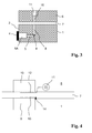
- Figure 4 shows a detailed view of a detail Fig. 3 with a first embodiment of a microwave coupler according to the invention for low-attenuation overcoming of the air gap 7 between the stator 6 and the work spindle 1.
- the channel section 8 is effective as a hollow waveguide
- the channel section 10 is as short as possible, preferably as in transitions between hollow waveguides and coaxial known in a length of one quarter of the waveguide wavelength , the channel section 10.
- a mounted on the surface of the channel section 10 monopoly 12 is connected via a supply line with a measuring device 11, which includes a transmitting and receiving unit for microwave signals and a signal processing device.
- the feed of a Microwave signal through the measuring device 11 and causes the excitation of itself in the direction of the channel section 8 in the work spindle 1 propagating waves.
- the measuring device 11 is arranged on the outside of the stator 6 and connected by a feed line, which is laid in an additional channel in the stator 6, with the monopole 12, which in Fig. 4 not shown in detail.
- This waveguide coupling across the air gap 7 can also be applied to the reverse propagation direction in the sense of the reciprocity theorem.
- a monopole 13 which is directly connected to the work spindle 1 at the edge 14 of the channel section 8, is likewise attached to the end of the channel section 8 in the work spindle 1. The close proximity between the monopole 12 on the side of the stator 6 and the monopole 13 connected to the work spindle 1 causes a coupling with low attenuation of the transfer of microwave power through the air gap 7 in both directions.
- Fig. 5 shows a further embodiment of a microwave coupler for low-attenuation overcoming of the air gap 7 between the work spindle 1 and the stator 6 of the machine tool.
- bodies of dielectric material such as potting compound or ceramic are attached. These have mutually coaxial bores, in each of which an end segment of the inner conductor 15 or 16 of a coaxial line is inserted.
- Such a dielectric body constitutes a waveguide which is excited by the end segment of the inner conductor 15 or 16 extending rectilinearly in it in the E01 mode.
- the outer conductor of the respective coaxial line is connected to the work spindle 1 or to the stator 6.
- the coaxial line with the inner conductor 15 extends from the channel section 8 on via channel sections 9 and 5 and is at the end of the channel section 5 to the microwave resonator 4, 5A (FIG. Fig. 3 ).
- the coaxial line with the inner conductor 16 extends in a continuous channel section 10 in the stator 6 and is connected at its other end to a measuring device 11.
- the H11 mode can also be stimulated.
- the respective inner conductor 15 or 16 of the coaxial line must be guided in the end section 8A or 10A of the channel 8 or 10 in the form of a loop, ie it must first be a certain length extend in its original direction perpendicular to the surface of the work spindle or the stator in the end portion 8A or 10A, then a certain length transverse to this direction and finally parallel to this direction back to the surface of the work spindle 1 and the stator 6, as is in Fig. 6 shown with dashed lines.
- the inner conductor 15 or 16 is electrically connected in this case with the surface of the work spindle 1 and the stator 6.
- the excitation of the H11 mode has the advantage of lower losses compared to the E01 mode.
- FIG. 6 schematically is a part of this embodiment of a microwave coupler according to the invention, namely the slot antenna in the work spindle 1 in a radial plan view of the work spindle 1 is shown.
- the longitudinal axis of the work spindle 1 is characterized by a dashed horizontal line.
- the slot antenna consists in a circumferentially extending slot 17, to which a coaxial line 18 is coupled, which in a radial section 8 of a in Fig. 6 invisible channel 5, 8, 9 inside the work spindle 1, as in Fig. 3 is shown is misplaced.
- the inner conductor 19 and the outer conductor 20 of the coaxial line 18 are electrically connected at opposite locations on the long sides of the slot 17 at a defined distance from a longitudinal end of the slot 17 with its edge.
- the slot antenna in the stator 6 is at the same axial position and is as in the embodiment of FIG Fig. 5 Connected via a laid in a continuous channel section 10 in the stator 6 coaxial line with a measuring device 11.
- the slot in the stator 6 also extends in the circumferential direction, so that for a maximum rotation angle range, an overlap of the opposing slot antennas, which allows a transmission of a microwave signal across the air gap 7 away.
- a patch antenna An alternative to a slot antenna as a component of a microwave coupler for signal transmission according to the invention across the air gap 7 is a patch antenna
- the arranged on the work spindle 1 part of this embodiment of a microwave coupler is in Fig. 7 in two views, namely left in a sectional view and right in a radial plan view of the work spindle 1 shown.
- the sectional view refers to the dashed line in the plan view, which as well as in Fig. 6 the longitudinal axis of the work spindle 1 corresponds.
- the patch antenna is arranged in a recess in the work spindle 1, which forms an end section 8A with an enlarged cross-section of a radial channel section 8.
- dielectric body 21 for example a printed circuit board made of plastic or ceramic material, with two mutually parallel surfaces.
- the lower surface is covered over its entire surface by a metal layer 22, which forms the ground plane of the patch antenna and rests on the bottom of the end portion 8A.
- a patch acting as a microwave radiator patch 23 On the opposite surface, which faces the air gap 7, there is a patch acting as a microwave radiator patch 23, namely a metal layer of rectangular shape and defined dimensions which are smaller than the overall dimensions of this surface.
- the inner conductor 15 of a laid in the channel section 8 coaxial line extends through a hole in the dielectric 21 through to the patch 23 and is electrically connected thereto at a defined location outside of its center.
- the outer conductor of the coaxial line is connected to the metal layer 22 on the opposite surface.
- the part of the channel section 8A above the patch antenna is preferably also filled by a dielectric, which may in particular be a potting compound made of plastic.
- a mirror image arrangement of a patch antenna is provided at the same axial position in the surface of the stator 6.
- FIG. 8 Another embodiment of a transmission device for low-damping overcoming of the air gap 7 between the work spindle 1 and the stator 6 of a machine tool is in Fig. 8 shown.
- the two channel sections 8 and 10 there extend first conically in transition sections 8B and 10B and end at the air gap 7 in cylindrical end sections 8A and 10A of larger diameter.
- the channel sections 8 and 10 act as hollow waveguides and are filled to their ends, ie including the conical transition sections 8B and 10B and the cylindrical end sections 8A and 10A, with a material of relatively low permittivity.
- the conical sections 8B and 10B are coaxially inserted or embedded bodies 24 and 25 of a material of higher permittivity, which also in the region of the cylindrical end portions 8A and 10A also a cylindrical shape and in the region of the conical transition portions 8B and Fig. 10B has a conical shape with the tip of the cone of a body 24 and 25 respectively extending to the inner end of the conical channel portion 8B and 10B, respectively.
- the bodies 24 and 25 of higher permittivity may also each be composed of two parts, namely a cylindrical part and a conical part.
- the lower permittivity dielectric in the region of the transition sections 8B and 10B and the end sections 8A and 10A may be a separate body from the dielectric filling of the adjoining channel sections 8 and 10, which in turn may in turn be composed of two parts.
- a plurality of channels 5, 8, 9 may be provided in the work spindle 1, the respective radial portions 8 alternately pass in the course of a revolution of the work spindle 1 with the channel section 10 in the stator 6 aligned position.
- several measuring devices 11 could be distributed on the circumference of the stator 6.
- the bipartite of the microwave coupler according to the invention does not therefore mean that it consists of only two parts. Rather, it means that at least one part on the work spindle 1 and at least one other second part suitable for signal transmission from and to the first part is arranged on the stator 6.
Landscapes
- Engineering & Computer Science (AREA)
- Mechanical Engineering (AREA)
- Physics & Mathematics (AREA)
- Optics & Photonics (AREA)
- Electromagnetism (AREA)
- Length-Measuring Devices Using Wave Or Particle Radiation (AREA)
- Magnetic Bearings And Hydrostatic Bearings (AREA)
- Machine Tool Sensing Apparatuses (AREA)
- Waveguide Connection Structure (AREA)
Abstract
Description
- Die Erfindung betrifft eine Vorrichtung zur Überwachung der Lage eines Werkzeugs oder Werkzeugträgers an einer Arbeitsspindel nach dem Oberbegriff des Anspruchs 1.
- Während der von modernen numerisch gesteuerten Werkzeugmaschinen vollzogenen Bearbeitungsvorgänge sind häufige schnelle, im Allgemeinen automatisch durchgeführte Werkzeugwechsel notwendig. Die hierfür eingesetzten Spannvorrichtungen sind meistens modular zweiteilig ausgeführt und weisen zueinander korrespondierende Plananlagen auf, die, unterstützt von sehr großen Spannkräften, für einen präzisen und steifen Sitz der Werkzeuge sorgen. Allerdings existiert bei der Kontaktierung der zueinander komplementären Plananlagen ein wesentlicher Störfaktor, der sich notwendigerweise aus den Betriebsbedingungen von spanabhebend bearbeitenden Werkzeugmaschinen ergibt. Sofern das in Form von mitunter sehr feinen Spänen vorhandene abgetragene Material aus dem Wirkbereich der Maschinen nicht vollständig entfernt werden kann, besteht in Zusammenwirken mit den hierfür verwendeten Mitteln, z.B. Bohr- und Schneidemulsionen, die Möglichkeit der Anhaftung von Spänen auf den Plananlagen. Hierdurch ist in den meisten Fällen eine Fehlausrichtung des Werkzeugs und unzureichende Steifigkeit der Einspannung zu erwarten. Sehr feine Späne führen zu kaum bemerkbaren Fehleinspannungen, die aber trotzdem ein unzureichendes Bearbeitungsergebnis zur Folge haben.
- Aus der
DE 10 2009 005 745 A1 ist eine Überwachungsvorrichtung zur Erkennung solcher Fehleinspannungen bekannt. Die Funktion dieser Überwachungsvorrichtung basiert auf der Ausbreitung eines Radarsignals in einem innerhalb der Arbeitsspindel durch mehrere Bohrungen gebildeten Kanal, der im Betrieb unmittelbar durch eine Plananlagefläche des Werkzeugs oder Werkzeugträgers abgeschlossen wird, wobei der Endbereich des Kanals als Hohlraumresonator ausgebildet ist. Eine fehlerhafte Anlage des Werkzeugs oder Werkzeugträgers an der Werkzeugspannvorrichtung kann anhand eines Radarsignals detektiert werden, das in den Kanal von einem außerhalb der Arbeitsspindel angeordneten Sender eingestrahlt, an dem Werkzeug oder Werkzeugträger reflektiert und durch den Kanal zu dem Sender zurückgeleitet wird. - Dabei ist der Sender an einem Stator angeordnet, in dem die Arbeitsspindel drehbar gelagert ist, und das Radarsignal wird zunächst in einen Kanal in dem Stator, mit dem der Kanal in der Arbeitsspindel in einer Winkelposition der Arbeitsspindel fluchtet, eingestrahlt und passiert zwischen dem Stator und der Arbeitsspindel auf den Hin- und Rückweg einen Luftspalt zwischen dem Stator und der Arbeitsspindel. Dieser Luftspalt verursacht durch Reflexion und Dämpfung eine Beeinträchtigung der Qualität des Messsignals.
- Die Aufgabe der Erfindung ist es, bei der aus der vorausgehend genannten Schrift bekannten Überwachungsvorrichtung die Qualität des Messsignals zu verbessern.
- Diese Aufgabe wird erfindungsgemäß durch eine Vorrichtung mit den Merkmalen des Anspruchs 1 gelöst. Vorteilhafte Ausgestaltungen sind in den Unteransprüchen angegeben.
- Erfindungsgemäß ist bei einer gattungsgemäßen Überwachungsvorrichtung an derjenigen axialen Position, an welcher ein Kanalabschnitt an der äußeren Oberfläche der Arbeitsspindel endet, ein zweiteiliger richtungssymmetrischer passiver Mikrowellenkoppler angeordnet, von dem ein erster Teil an oder in einem Ende des Kanalabschnitts in der Arbeitsspindel und ein zweiter Teil an oder in einem Ende eines Kanalabschnitts in dem Stator so angeordnet ist, dass sich die beiden Teile des Mikrowellenkopplers in einer vorbestimmten Winkelposition der Arbeitsspindel zur Übertragung eines Mikrowellensignals über den Luftspalt hinweg gegenüberstehen. Gegenüber dem Stand der Technik, bei dem in einer vorbestimmten Winkelposition lediglich zwei Bohrungen auf beiden Seiten des Luftspalts in eine fluchtende Ausrichtung gelangen, kann die Beeinträchtigung der Signalqualität des Messsignals beim Übergang über den Luftspalt durch die Anordnung eines zweiteiligen Mikrowellenkopplers deutlich verringert werden. Von wesentlicher Bedeutung ist hierbei die Richtungssymmetrie der Übertragungscharakteristik, da sowohl ein Sendesignal, als auch ein Reflexionssignal den Luftspalt in einander entgegengesetzten Richtungen möglichst verlustarm überwinden müssen.
- In einer vorteilhaften Ausführungsform weist der erste Teil des Mikrowellenkopplers eine Monopolantenne auf, die über dem Ende des Kanalabschnitts in der Arbeitsspindel angeordnet und an einem Ende mit der Arbeitsspindel elektrisch leitend verbunden ist, und der zweite Teil des Mikrowellenkopplers weist eine Monopolantenne auf, die über dem Ende des Kanalabschnitts in dem Stator in derselben Richtung wie die andere Monopolantenne angeordnet und über eine Leitung mit der Messeinrichtung verbunden ist. Der Kanalabschnitt in dem Stator hat die Form einer Sackbohrung, deren Tiefe vorzugsweise ein Viertel der Hohlleiterwellenlänge des Kanalabschnitts in dem Stator beträgt. Diese Ausführungsform eignet sich zur dämpfungsarmen Überwindung des Luftspalts, wenn der Kanal in der Arbeitsspindel als Hohlwellenleiter für das Messsignal benutzt werden soll.
- Wenn das Messsignal bis auf den Luftspalt über eine Koaxialleitung übertragen werden soll und folglich in den an dem Luftspalt endenden Kanalabschnitten sowohl in der Arbeitsspindel, als auch in dem Stator jeweils eine Koaxialleitung angeordnet ist, kann ein dämpfungsarmer Mikrowellenkoppler dadurch realisiert werden, dass besagte Kanalabschnitte jeweils einen von einem Dielektrikum ausgefüllten Endabschnitt aufweisen und sich der Innenleiter der jeweiligen Koaxialleitung um ein vorbestimmtes Maß in das Dielektrikum in dem Endabschnitt hinein erstreckt. Hierbei ist es vorteilhaft, wenn die zwei Teile des Mikrowellenkopplers jeweils einen Bereich mit vergrößertem Querschnitt der an dem Luftspalt endenden Kanalabschnitte aufweisen.
- Eine andere bevorzugte Ausführungsform eines Mikrowellenkopplers für die Übertragung des Messsignals über eine Koaxialleitung besteht darin, in den einander gegenüberliegenden Kanalabschnitten in der Arbeitsspindel und in dem Stator jeweils eine Koaxialleitung anzuordnen und an den Enden beider Kanalabschnitte eine an die jeweilige Koaxialleitung angeschlossene Schlitzantenne anzuordnen, wobei die Längsrichtung des Schlitzes die Umfangsrichtung der Arbeitsspindel bzw. der dieser gegenüberliegenden Oberfläche des Stators ist. Auch hierdurch wird eine verlustarme Überwindung des Luftspalts ermöglicht. Eine ebenfalls vorteilhafte Ausführungsform eines Mikrowellenkopplers für die Übertragung des Messsignals über eine Koaxialleitung ist eine Patchantenne.
- Eine andere vorteilhafte Ausführungsform eines Mikrowellenkopplers für die Signalübertragung durch als Hohlleiter wirksame Kanäle in der Arbeitsspindel und in dem Stator besteht in der Ausbildung jeweils eines Bereiches mit vergrößertem Querschnitt am Ende jedes Kanalabschnitts an dem Luftspalt, wobei dieser Bereich zumindest einen sich in Richtung des Luftspaltes konisch erweiternden Abschnitt aufweist, der durch zwei verschiedene Dielektrika ausgefüllt ist, indem mittig und koaxial zur Längsachse des jeweiligen Kanals ein konischer Körper aus einem Dielektrikum mit einer höheren Permittivität angeordnet ist, der radial von einem Dielektrikum mit einer niedrigeren Permittivität umgeben ist. Vorzugsweise weist der Bereich mit vergrößertem Querschnitt jeweils einen an dem Luftspalt endenden Abschnitt mit konstanten Querschnitt auf.
- Weitere besonders vorteilhafte Merkmale der Erfindung sind den Unteransprüchen zu entnehmen.
- Nachfolgend werden Ausführungsbeispiele der Erfindung unter Bezugnahme auf die Zeichnungen beschrieben. In diesen zeigt
- Fig. 1
- eine Vorderansicht einer Arbeitsspindel,
- Fig. 2
- eine schematische Schnittansicht einer fehlerhaften Werkzeugspannung,
- Fig.3
- eine schematische Längsschnittansicht einer Vorrichtung zur Überwachung der Werkzeugplananlage,
- Fig. 4
- eine schematische Darstellung einer ersten Ausführungsform eines erfindungsgemäßen Mikrowellenkopplers,
- Fig. 5
- eine schematische Darstellung einer zweiten Ausführungsform eines erfindungsgemäßen Mikrowellenkopplers,
- Fig. 6
- eine schematische Darstellung einer Schlitzantenne, die Bestandteil einer dritten Ausführungsform eines erfindungsgemäßen Mikrowellenkopplers ist,
- Fig. 7
- eine schematische Darstellung einer Patchantenne, die Bestandteil einer vierten Ausführungsform eines erfindungsgemäßen Mikrowellenkopplers ist, und
- Fig. 8
- eine schematische Darstellung einer fünften Ausführungsform eines
-
Fig. 1 zeigt die Vorderansicht einer Arbeitsspindel 1, die Bestandteil einer nicht dargestellten Bearbeitungsmaschine, insbesondere einer Werkzeugmaschine ist. Die Arbeitsspindel 1 weist an ihrer Stirnseite eine oder mehrere ebene Anlageflächen 2 auf, an denen ein Werkzeug oder ein Werkzeugträger im gespannten Zustand plan anliegen soll. Im Falle mehrerer separater Anlageflächen 2 liegen diese genau planparallel zueinander in einer einzigen Ebene. Zur Verwendung an der Arbeitsspindel 1 bestimmte Werkzeuge oder Werkzeugträger, wobei letztere ihrerseits verschiedene Werkzeuge aufnehmen können, weisen an ihrer Rückseite ebenfalls entsprechende stirnseitige Anlageflächen auf. Bei einer planen Anlage der werkzeugseitigen bzw. werkzeugträgerseitigen Anlageflächen an der spindelseitigen Anlagefläche 2 verläuft die Längsachse des Werkzeugs bzw. Werkzeugträgers genau parallel zur Längsachse der Arbeitsspindel 1. Die Zentrierung des Werkzeugs bzw. Werkzeugträgers bezüglich der Arbeitsspindel 1 erfolgt durch kegelförmige Auflageflächen im Inneren der Arbeitsspindel 1. - Im Fall einer Verschmutzung einer Anlagefläche 2 ist keine plane Anlage des Werkzeugs oder Werkzeugträgers an der Arbeitsspindel 1 mehr möglich. Insbesondere kann eine solche Verschmutzung durch bei der Bearbeitung eines Werkstücks anfallende Späne erfolgen. Schematisch ist eine solche Situation in
Fig. 2 dargestellt. Auf dem rechten Teil der Anlagefläche 2 liegt ein Span 3, der beim Spannen des Werkzeugs 4 an der Arbeitsspindel 1 zwischen dieser und dem Werkzeug 4 eingeklemmt wird und dafür sorgt, dass ein keilförmiger Spalt zwischen beiden besteht. Bei der Bearbeitung eines Werkstücks mit einem solchermaßen schrägstehenden Werkzeug 4 ist kein maßhaltiges Ergebnis, sondern Ausschuss zu erwarten. - An der Anlagefläche 2 sind mehrere, im gezeigten Beispiel drei in Axialrichtung der Arbeitsspindel 1 verlaufende Kanalabschnitte 5 in Form von Bohrungen vorgesehen, von denen in
Fig. 1 jeweils der stirnseitige Austritt aus der Arbeitsspindel 1 sichtbar ist.Fig. 3 zeigt eine schematische Längsschnittansicht eines Ausschnitts der Arbeitsspindel 1 und eines Stators 6, in dem die Arbeitsspindel 1 an einer inFig. 3 nicht sichtbaren Stelle drehbar gelagert ist, und von dem sie in dem inFig. 3 sichtbaren Bereich durch einen dünnen Luftspalt 7 getrennt ist. Dort ist nur der obere der drei axialen Kanalabschnitte 5 vonFig. 1 zu sehen. Dieser trifft im Inneren der Arbeitsspindel 1 auf einen in Radialrichtung der Arbeitsspindel 1 verlaufenden Kanalabschnitt 8, wodurch ein dritter Kanalabschnitt 9 definiert wird, in dem der durch die einzelnen Abschnitte 5, 8 und 9 gebildete, durchgehende Kanal seine Richtung um 90° ändert. In gleicher Weise trifft auch jeder der beiden anderen, inFig. 3 nicht sichtbaren axialen Kanalabschnitte 5 jeweils auf einen zugeordnete radialen Kanalabschnitt 8 in der Arbeitsspindel 1. In der inFig. 3 gezeigten Winkelstellung der Arbeitsspindel 1 fluchtet der radiale Kanalabschnitt 8 in der Arbeitsspindel 1 mit einem radialen Kanalabschnitt 10 in dem Stator 6. - In einem sich von außen in den Stator 6 erstreckenden Hohlraum ist eine elektronische Messeinrichtung 11 in Form eines Radarsystems, das einen Sender, einen Empfänger und eine Antenne umfasst, angeordnet. Die Antenne ist auf den Kanalabschnitt 10 in dem Stator 6 ausgerichtet, um die Einstrahlung eines Radarsignals in den Kanalabschnitt 10 und den Empfang eines Radarsignals aus dem Kanalabschnitt 10 zu ermöglichen. Der Kanalabschnitt 10 fungiert ebenso wie die Kanalabschnitte 5, 8 und 9 für eine eingestrahlte elektromagnetische Welle als Hohlleiter, wie aus der Radartechnik hinreichend bekannt ist.
- In der in
Fig. 3 gezeigten Winkelposition der Arbeitsspindel 1 besteht somit insgesamt ein als Hohlleiter wirksamer Kanal 5, 8, 9, 10 zwischen der Messeinrichtung 11 und der rückwärtigen Auflagefläche des Werkzeugs 4, mit dem dieses auf der Auflagefläche 2 der Arbeitsspindel 1 aufliegt. Ein von der Messeinrichtung 11 in den Kanalabschnitt 10 eingestrahltes Radarsignal breitet sich über den Kanalabschnitt 10, den damit fluchtenden Kanalabschnitt 8 und die Kanalabschnitte 9 und 5 bis zu der rückwärtigen Auflagefläche des Werkzeugs 4 aus, wobei es in dem Kanalabschnitt 9 um 90° umgelenkt wird. Dabei führt der Kanal 5, 8, 9, 10 die sich in ihm ausbreitende elektromagnetische Welle im Sinne eines Hohlleiters. An der rückwärtigen Auflagefläche des Werkzeugs 4 wird das Radarsignal reflektiert und läuft in dem Kanal 5, 8, 9, 10 in entgegengesetzter Richtung bis zu der Messeinrichtung 11 zurück, wo es empfangen und verarbeitet wird, um die exakte Lage des Werkzeugs 4 bezüglich der Auflagefläche 2 der Arbeitsspindel 1 zu ermitteln. - Falls der Kanal 5, 8, 9, 10 mit einem Dielektrikum gefüllt ist, ändert sich die Grenzfrequenz, ab welcher der Kanal 5, 8, 9, 10 als Hohlleiter wirksam ist. Es ist äußerst zweckmäßig, den Kanal 5, 8, 9, 10 zumindest im Bereich des werkzeugseitigen Abschnitts 5 mit einem Dielektrikum zu füllen, um ein Eindringen von Schmutz und Spänen, welches die Wellenausbreitung offensichtlich stören würde, zu verhindern. Zur Schaffung homogener Ausbreitungseigenschaften ist es jedoch bevorzugt, den gesamten Kanal 5, 8, 9, 10 mit einem Dielektrikum zu füllen. Geeignet ist hierfür beispielsweise eine Vergussmasse auf Polyurethanbasis.
- Zur Erhöhung der Empfindlichkeit ist es zweckmäßig, den Abschnitt 5 so zu gestalten, dass eine möglichst ausgeprägte Resonanz auftritt, was in
Fig. 3 durch eine Erweiterung am werkzeugseitigen Ende zu einer Kammer 5A, die zusammen mit der rückwärtigen Oberfläche des Werkzeugs 4 einen Mikrowellenresonator bildet, schematisch dargestellt ist. Hierdurch kann ein Resonator hoher Güte realisiert werden, dessen Resonanzfrequenz von der Lage der rückwärtigen Auflagefläche des Werkzeugs 4 bezüglich der Arbeitsspindel 1 abhängt. Ein solcher Mikrowellenresonator wird bereits bei einer geringfügigen Abweichung der Lage des Werkzeugs 4 von einer perfekten Plananlage an der Auflagefläche 2 der Arbeitsspindel 1 verstimmt, was anhand einer Messung des Reflexionskoeffizienten bei einer Variation der Frequenz des eingestrahlten Signals durch eine in dem Radarsystem 11 enthaltene Signalverarbeitungseinrichtung detektiert werden kann. - Die vorausgehend beschriebene Vorrichtung entspricht dem aus der zuvor genannten
DE 10 2009 005 745 A1 bekannten Stand der Technik. Auf die Funktion dieser Vorrichtung hat außer dem Kanal 5, 8, 9, 10 und der Kammer 5A auch der zwischen dem Stator 6 und der rotierenden Arbeitsspindel 1 vorhandenen Luftspalt 7, an dem die Kanalabschnitte 8 und 10 miteinander fluchtend enden, einen Einfluss. Wie die Vorrichtung erfindungsgemäß verbessert werden kann, um den Einfluß dieses Luftspalts 7 zu minimieren, wird nachfolgend anhand der weiterenFiguren 4 bis 9 erläutert. -
Fig.4 zeigt eine Detailansicht eines Ausschnitts ausFig. 3 mit einer ersten Ausführungsform eines erfindungsgemäßen Mikrowellenkopplers zur dämpfungsarmen Überwindung des Luftspalts 7 zwischen dem Stator 6 und der Arbeitsspindel 1. Während der Übertragung eines Messsignals über den Luftspalt 7 hinweg steht die Öffnung in der Arbeitsspindel 1, in welcher sich der als Hohlwellenleiter wirksame Kanalabschnitt 8 befindet, fluchtend gegenüber einem in diesem Fall als Sackbohrung ausgebildeten und ebenfalls als Hohlwellenleiter wirksamen Kanalabschnitt 10 gleichen Durchmessers in dem Stator 6. Der Kanalabschnitt 10 ist möglichst kurz ausgeführt, vorzugsweise wie bei Übergängen zwischen Hohlwellenleitern und Koaxialleitungen bekannt, in einer Länge von einem Viertel der Hohlleiterwellenlänge, des Kanalabschnitts 10. - Ein auf der Oberfläche des Kanalabschnitts 10 angebrachter Monopol 12 ist über eine Zuleitung mit einer Messeinrichtung 11 verbunden, die eine Sende- und Empfangseinheit für Mikrowellensignale sowie eine Signalverarbeitungseinrichtung enthält. Die Einspeisung eines Mikrowellensignals durch die Messeinrichtung 11 und bewirkt die Anregung von sich in Richtung des Kanalabschnitts 8 in der Arbeitsspindel 1 ausbreitenden Wellen. Die Messeinrichtung 11 ist an der Außenseite des Stators 6 angeordnet und durch eine Zuleitung, die in einem zusätzlichen Kanal in dem Stator 6 verlegt ist, mit dem Monopol 12 verbunden, was in
Fig. 4 nicht im einzelnen dargestellt ist. - Diese Wellenleiterkopplung über den Luftspalt 7 hinweg lässt sich im Sinne des Reziprozitätstheorems auch auf die umgekehrter Ausbreitungsrichtung anwenden. Zur Unterstützung der Überwindung des Luftspalts 7 ist hierzu am Ende des Kanalabschnitts 8 in der Arbeitsspindel 1 ebenfalls ein Monopol 13 angebracht, welcher mit der Arbeitsspindel 1 am Rand 14 des Kanalabschnitts 8 direkt verbunden ist. Die enge Nachbarschaft zwischen dem Monopol 12 auf der Seite des Stators 6 und dem mit der Arbeitsspindel 1 verbundenen Monopol 13 bewirkt eine Kopplung mit geringer Dämpfung des Übertritt von Mikrowellenleistung über den Luftspalt 7 in beiden Richtungen.
-
Fig. 5 zeigt eine weitere Ausführungsform eines Mikrowellenkopplers zur dämpfungsarmen Überwindung des Luftspalts 7 zwischen der Arbeitsspindel 1 und dem Stator 6 der Werkzeugmaschine. In zueinander spiegelsymmetrischen Ausnehmungen in der Arbeitsspindel 1 und dem Stator 6, welche Endabschnitte 8A und 10A der dortigen Kanalabschnitte 8 bzw. 10 bilden, sind Körper aus dielektrischem Material wie Vergussmasse oder Keramik angebracht. Diese weisen zueinander koaxiale Bohrungen auf, in welche jeweils ein Endsegment des Innenleiters 15 bzw. 16 einer Koaxialleitung eingeführt ist. Ein solcher dielektrischer Körper stellt einen Wellenleiter dar, der durch das Endsegment des sich geradlinig in ihn hinein erstreckenden Innenleiters 15 bzw. 16 im E01-Mode angeregt wird. Der Außenleiter der jeweiligen Koaxialleitung ist mit der Arbeitsspindel 1 bzw. mit dem Stator 6 verbunden. Die Koaxialleitung mit dem Innenleiter 15 verläuft von dem Kanalabschnitt 8 aus weiter über Kanalabschnitte 9 und 5 und ist am Ende des Kanalabschnitts 5 an den Mikrowellenresonator 4, 5A (Fig. 3 ) angekoppelt. Die Koaxialleitung mit dem Innenleiter 16 verläuft in einem durchgehenden Kanalabschnitt 10 in dem Stator 6 und ist an ihrem anderen Ende mit einer Messeinrichtung 11 verbunden. - Alternativ zum E01-Mode kann auch der H11-Mode angeregt werden. Hierzu muss der jeweilige Innenleiter 15 bzw. 16 der Koaxialleitung in dem Endabschnitt 8A bzw. 10A des Kanals 8 bzw. 10 in Form einer Schleife geführt werden, d.h. er muss sich zunächst eine bestimmte Länge in seiner ursprünglichen Richtung senkrecht zur Oberfläche der Arbeitsspindel bzw. des Stators in den Endabschnitt 8A bzw. 10A hinein erstrecken, dann eine bestimmte Länge quer zu dieser Richtung und schließlich parallel zu dieser Richtung zurück bis zur Oberfläche der Arbeitsspindel 1 bzw. des Stators 6, wie es in
Fig. 6 mit gestrichelten Linien dargestellt ist. An seinem Ende ist der Innenleiter 15 bzw. 16 in diesem Fall mit der Oberfläche der Arbeitsspindel 1 bzw. des Stators 6 elektrisch verbunden. Die Anregung des H11-Mode hat gegenüber dem E01-Mode den Vorteil geringerer Verluste. - Eine weitere verlustarme Möglichkeit der Überbrückung des Luftspalts 7 besteht in der Platzierung jeweils einer an die zu übertragende Wellenlänge angepassten Schlitzantenne auf der Arbeitsspindel 1 und an dem Stator 6, d.h. an den jeweiligen Enden der Kanalabschnitte 8 und 10 an dem Luftspalt 7. Die Schmalseiten dieser Schlitzantennen verlaufen in diesem Fall in Axialrichtung der Arbeitsspindel 1 und die Langseiten folglich in Umfangsrichtung. In
Fig. 6 ist schematisch ein Teil dieser Ausführungsform eines erfindungsgemäßen Mikrowellenkopplers, nämlich die Schlitzantenne in der Arbeitsspindel 1 in einer radialen Draufsicht auf die Arbeitsspindel 1 dargestellt. Die Längsachse der Arbeitsspindel 1 ist dort durch eine gestrichelte waagrechte Linie gekennzeichnet. - Die Schlitzantenne besteht in einem in Umfangsrichtung verlaufenden Schlitz 17, an den eine Koaxialleitung 18 gekoppelt ist, welche in einem radialen Abschnitt 8 eines in
Fig. 6 nicht sichtbaren Kanals 5, 8, 9 im Inneren der Arbeitsspindel 1, wie er inFig. 3 gezeigt ist, verlegt ist. Der Innenleiter 19 und der Außenleiter 20 der Koaxialleitung 18 sind an gegenüberliegenden Stellen an den Langseiten des Schlitzes 17 in einem definiertem Abstand von einem Längsende des Schlitzes 17 elektrisch mit dessen Rand verbunden. Die Schlitzantenne in dem Stator 6 befindet sich an derselben axialen Position und ist wie bei der Ausführungsform vonFig. 5 über eine in einem durchgehenden Kanalabschnitt 10 in dem Stator 6 verlegte Koaxialleitung mit einer Messeinrichtung 11 verbunden. Der Schlitz in dem Stator 6 verläuft ebenfalls in Umfangsrichtung, so dass für einen größtmöglichen Rotationswinkelbereich eine Überlappung der einander gegenüberliegenden Schlitzantennen besteht, die eine Übertragung eines Mikrowellensignals über den Luftspalt 7 hinweg ermöglicht. - Eine Alternative zu einer Schlitzantenne als Komponente eines Mikrowellenkopplers zur erfindungsgemäßen Signalübertragung über den Luftspalt 7 hinweg stellt eine Patchantenne dar. Der an der Arbeitsspindel 1 angeordnete Teil dieser Ausführungsform eines Mikrowellenkopplers ist in
Fig 7 in zwei Ansichten, nämlich links in einer Schnittansicht und rechts in einer radialen Draufsicht auf die Arbeitsspindel 1 gezeigt. Die Schnittansicht bezieht sich auf die gestrichelte Linie in der Draufsicht, welche ebenso wie inFig. 6 der Längsachse der Arbeitsspindel 1 entspricht. Die Patchantenne ist in einer Ausnehmung in der Arbeitsspindel 1, welche einen Endabschnitt 8A mit vergrößertem Querschnitt eines radialen Kanalabschnitts 8 bildet, angeordnet. - Sie weist einen dielektrischen Körper 21, beispielsweise eine Leiterplatte aus Kunststoff oder Keramikmaterial, mit zwei zueinander parallelen Oberflächen auf. Die untere Oberfläche ist ganzflächig von einer Metallschicht 22 bedeckt, welche die Masseebene der Patchantenne bildet und auf dem Boden des Endabschnitts 8A aufliegt. Auf der gegenüberliegenden Oberfläche, die dem Luftspalt 7 zugewandt ist, befindet sich ein als Mikrowellenstrahler wirkendes Patch 23, nämlich eine Metallschicht von rechteckiger Form und definierten Abmessungen, die geringer sind als die Gesamtabmessungen dieser Oberfläche.
- Der Innenleiter 15 einer in dem Kanalabschnitt 8 verlegten Koaxialleitung erstreckt sich durch eine Bohrung in dem Dielektrikum 21 hindurch bis zu dem Patch 23 und ist mit diesem an einer definierten Stelle außerhalb von dessen Zentrum elektrisch verbunden. Der Außenleiter der Koaxialleitung ist mit der Metallschicht 22 auf der gegenüberliegenden Oberfläche verbunden. Der Teil des Kanalabschnitts 8A oberhalb der Patchantenne ist vorzugsweise ebenfalls von einem Dielektrikum ausgefüllt, bei dem es sich insbesondere um eine Vergussmasse aus Kunststoff handeln kann. Eine spiegelbildliche Anordnung einer Patchantenne ist an der gleichen axialen Position in der Oberfläche des Stators 6 vorgesehen.
- Eine weitere Ausführungsform einer Übertragungseinrichtung zur dämpfungsarmen Überwindung des Luftspalts 7 zwischen der Arbeitsspindel 1 und dem Stator 6 einer Werkzeugmaschine ist in
Fig. 8 dargestellt. In der Arbeitsspindel 1 und im Stator 6 erweitern sich die beiden dortigen Kanalabschnitte 8 und 10 zunächst in Übergangsabschnitten 8B bzw. 10B konisch und enden an dem Luftspalt 7 in zylindrischen Endabschnitten 8A bzw. 10A mit größerem Durchmesser. Die Kanalabschnitte 8 und 10 fungieren als Hohlwellenleiter und sind bis zu ihren Enden, d.h. einschließlich der konischen Übergangsabschnitte 8B und 10B sowie der zylindrischen Endabschnitte 8A und 10A mit einem Material relativ niedriger Permittivität ausgefüllt. - In den Endabschnitten 8A und 10A und den konischen Abschnitten 8B und 10B sind koaxial Körper 24 bzw. 25 aus einem Material höherer Permittivität eingefügt oder eingebettet, die jeweils im Bereich der zylindrischen Endabschnitte 8A und 10A ebenfalls eine zylindrische Form und im Bereich der konischen Übergangsabschnitte 8B und 10B eine Kegelform haben, wobei die Spitze des Kegels eines Körpers 24 bzw. 25 jeweils bis zum inneren Ende des konischen Kanalabschnitts 8B bzw. 10B reicht. Die Körper 24 und 25 höherer Permittivität können auch jeweils aus zwei Teilen, nämlich einem zylindrischen und einem kegelförmigen Teil zusammengesetzt sein. Ebenso kann das Dielektrikum niedrigerer Permittivität im Bereich der Übergangsabschnitte 8B und 10B und der Endabschnitte 8A und 10A ein von der dielektrischen Füllung der anschließenden Kanalabschnitte 8 und 10 separater Körper sein, der wiederum seinerseits aus zwei Teilen zusammengesetzt sein kann.
- Aus einem der Kanalabschnitte 8 oder 10 ankommende Mikrowellen, die sich dort vorzugsweise im H11-Mode fortpflanzen, gehen aufgrund der beschriebenen Form und Permittivitätsverteilung der Übergangsabschnitte 8B und 10B und der Endabschnitte 8A und 10A innerhalb eines konischen Abschnitts 8B bzw. 10B in den LP01-Mode eines dielektrischen Wellenleiters über und treten in diesem Mode aus dem zylindrischen Endabschnitt 8A bzw. 10A in den Luftspalt 7 aus. Dessen Überwindung erfolgt aufgrund der stark reduzierten Wandströme des LP01-Modes mit einer reduzierten Reflexion.
- Auf die Funktionsweise der Messeinrichtung 11 wurde in der vorausgehenden Beschreibung nicht im einzelnen eingegangen, da hierzu in der eingangs genannten
DE 10 2009 005 745 A1 detaillierte Angaben vorhanden sind, auf die hiermit verwiesen wird. Diese Angaben beziehen sich zwar auf den Einsatz eines Radarsystems als Messeinrichtung 11 und setzen daher eine Wirkung des Kanals 5, 8, 9, 10 als Hohlwellenleiter für ein Radarsignal voraus. Wenn in dem Kanal 5, 8, 9, 10 stattdessen als Wellenleiter eine Koaxialleitung verlegt ist, ändert sich an der Messeinrichtung 11 lediglich deren Ankopplung an den Wellenleiter, für die in diesem Fall keine Antenne mehr benötigt wird, während das Funktionsprinzip der Reflexionsmessung aber dasselbe bleibt. Der korrekte Anschluss einer Koaxialleitung an eine Reflexionsmesseinrichtung ist in Fachkreisen bekannt und bedarf daher an dieser Stelle keiner Erläuterung. - Wie anhand
Fig. 1 erläutert wurde, können in der Arbeitsspindel 1 mehrere Kanäle 5, 8, 9 vorgesehen sein, deren jeweilige radiale Abschnitte 8 im Zuge einer Umdrehung der Arbeitsspindel 1 abwechselnd eine mit dem Kanalabschnitt 10 in dem Stator 6 fluchtende Position passieren. Auch könnten mehrere Messeinrichtungen 11 am Umfang des Stators 6 verteilt sein. Die Zweiteiligkeit des erfindungsgemäßen Mikrowellenkopplers bedeutet also nicht, dass er nur aus genau zwei Teilen besteht. Vielmehr ist damit gemeint, dass mindestens ein Teil an der Arbeitsspindel 1 und mindestens ein anderer zur Signalübertragung von und zu dem ersten Teil geeigneter zweiter Teil an dem Stator 6 angeordnet ist.
Claims (12)
- Vorrichtung zur Überwachung der Lage eines Werkzeugs (4) oder Werkzeugträgers an einer in einem Stator (6) drehbar gelagerten Arbeitsspindel (1), insbesondere in einer Bearbeitungsmaschine, mit mindestens einem Kanal (5, 8, 9), der von einer durch einen Luftspalt (7) von einer Oberfläche des Stators (6) getrennten äußeren Oberfläche der Arbeitsspindel (1) zu dem Werkzeug (4) oder Werkzeugträger führt und einen Pfad für die Ausbreitung eines elektromagnetischen Signals bildet, mit einer an dem Stator (6) angeordneten Messeinrichtung (11), welche eine Sendeeinheit zur Einkopplung eines elektromagnetischen Signals in den Kanal (5, 8, 9), eine Empfangseinheit zum Empfang eines aus dem Kanal (5, 8, 9) reflektierten Signals und eine Signalverarbeitungseinrichtung zur Ermittlung eines Maßes für die Lage des Werkzeugs (4) oder Werkzeughalters in Bezug auf die Arbeitsspindel (1) anhand des reflektierten Signals enthält, dadurch gekennzeichnet, dass an derjenigen axialen Position, an welcher ein Kanalabschnitt (8) an der äußeren Oberfläche der Arbeitsspindel (1) endet, ein zweiteiliger richtungssymmetrischer passiver Mikrowellenkoppler angeordnet ist, von dem ein erster Teil an oder in einem Ende des Kanalabschnitts (8) in der Arbeitsspindel (1) und ein zweiter Teil an oder in einem Ende eines Kanalabschnitts (10) in dem Stator (6) so angeordnet ist, dass sich die beiden Teile des Mikrowellenkopplers in einer vorbestimmten Winkelposition der Arbeitsspindel (1) zur Übertragung eines Mikrowellensignals über den Luftspalt (7) hinweg gegenüberstehen.
- Vorrichtung nach Anspruch 1, dadurch gekennzeichnet, dass sowohl der Kanalabschnitt (8) in der Arbeitsspindel (1), als auch der Kanalabschnitt (10) in dem Stator (6) von einem Dielektrikum ausgefüllt sind.
- Vorrichtung nach Anspruch 1 oder 2, dadurch gekennzeichnet, dass der erste Teil des Mikrowellenkopplers eine Monopolantenne (14) aufweist, die über dem Ende des Kanalabschnitts (8) in der Arbeitsspindel (1) angeordnet und an einem Ende mit der Arbeitsspindel (1) elektrisch leitend verbunden ist, dass der zweite Teil des Mikrowellenkopplers eine Monopolantenne (12) aufweist, die über dem Ende des Kanalabschnitts (10) in dem Stator (6) in derselben Richtung wie die andere Monopolantenne (14) angeordnet und über eine Leitung mit der Messeinrichtung (11) verbunden ist, und dass der Kanalabschnitt (10) in dem Stator (6) die Form einer Sackbohrung hat.
- Vorrichtung nach Anspruch 3, dadurch gekennzeichnet, dass die Tiefe der Sackbohrung ein Viertel der Hohlleiterwellenlänge des Kanalabschnitts (10) in dem Stator (6) beträgt.
- Vorrichtung nach Anspruch 1 oder 2, dadurch gekennzeichnet, dass der Kanalabschnitt (10) in dem Stator (6) bis zu der Messeinrichtung (11) führt und einen Pfad für elektromagnetische Signale zwischen der Messeinrichtung (11) und dem zweiten Teil des Mikrowellenkopplers bereitstellt.
- Vorrichtung nach einem Anspruch 5, dadurch gekennzeichnet, dass die zwei Teile des Mikrowellenkopplers jeweils einen Bereich (8A, 8B, 10A, 10B) mit vergrößertem Querschnitt des an dem Luftspalt (7) endenden Kanalabschnitts (8, 10) in der Arbeitsspindel (1) bzw. in dem Stator (6) aufweisen.
- Vorrichtung nach Anspruch 5 oder 6, dadurch gekennzeichnet, dass sowohl in dem Kanalabschnitt (8) in der Arbeitsspindel (1), als auch in dem Kanalabschnitt (10) in dem Stator (6) jeweils eine Koaxialleitung angeordnet ist, dass beide Teile des Mikrowellenkopplers einen von einem Dielektrikum ausgefüllten Endabschnitt (8A, 10A) des jeweiligen Kanalabschnitts (8, 10) aufweisen, und dass sich der Innenleiter (17, 18) der jeweiligen Koaxialleitung um ein vorbestimmtes Maß in das Dielektrikum in dem Endabschnitt (8A, 10A) hinein erstreckt.
- Vorrichtung nach Anspruch 7, dadurch gekennzeichnet, dass der Innenleiter in dem Dielektrikum in Form einer Schleife geführt ist und sein Ende mit einer Oberfläche des Endabschnitts (8A, 10A) des jeweiligen Kanalabschnitts (8, 10) elektrisch verbunden ist.
- Vorrichtung nach Anspruch 5 oder 6, dadurch gekennzeichnet, dass sowohl in dem Kanalabschnitt (8) in der Arbeitsspindel (1), als auch in dem Kanalabschnitt (10) in dem Stator (6) jeweils eine Koaxialleitung angeordnet ist, und dass beide Teile des Mikrowellenkopplers jeweils aus einer am Ende eines der Kanalabschnitte (8, 10) angeordneten und dort an die jeweilige Koaxialleitung angeschlossenen Schlitzantenne bestehen, wobei die Längsrichtung des Schlitzes (17) die Umfangsrichtung der Arbeitsspindel (1) bzw. der dieser gegenüberliegenden Oberfläche des Stators (6) ist.
- Vorrichtung nach Anspruch 5 oder 6, dadurch gekennzeichnet, dass sowohl in dem Kanalabschnitt (8) in der Arbeitsspindel (1), als auch in dem Kanalabschnitt (10) in dem Stator (6) jeweils eine Koaxialleitung angeordnet ist, und dass beide Teile des Mikrowellenkopplers jeweils aus einer am Ende eines der Kanalabschnitte (8, 10) angeordneten und dort an die jeweilige Koaxialleitung angeschlossenen Patchantenne (21, 22, 23) bestehen.
- Vorrichtung nach Anspruch 6, dadurch gekennzeichnet, dass der jeweilige Bereich mit vergrößertem Querschnitt (8A, 8B, 8A, 10B) zumindest einen sich in Richtung des Luftspaltes (7) konisch erweiternden Abschnitt (8B, 10B) enthält und durch zwei verschiedene Dielektrika ausgefüllt ist, indem mittig und koaxial zur Längsachse des jeweiligen Kanals (8, 10) ein ebenfalls konischer Körper (24, 25) aus einem Dielektrikum mit einer höheren Permittivität angeordnet ist, der radial von einem Dielektrikum mit einer niedrigeren Permittivität umgeben ist.
- Vorrichtung nach Anspruch 6 oder 11, dadurch gekennzeichnet, dass der Bereich mit vergrößertem Querschnitt (8A, 8B, 8A, 10B) jeweils einen an dem Luftspalt (7) endenden Abschnitt (8A, 10A) mit konstanten Querschnitt aufweist.
Applications Claiming Priority (1)
| Application Number | Priority Date | Filing Date | Title |
|---|---|---|---|
| DE102013100979.4A DE102013100979B3 (de) | 2013-01-31 | 2013-01-31 | Vorrichtung zur Überwachung der Lage eines Werkzeugs oder Werkzeugträgers an einer Arbeitsspindel |
Publications (3)
| Publication Number | Publication Date |
|---|---|
| EP2762268A2 true EP2762268A2 (de) | 2014-08-06 |
| EP2762268A3 EP2762268A3 (de) | 2014-09-03 |
| EP2762268B1 EP2762268B1 (de) | 2018-06-06 |
Family
ID=49943185
Family Applications (1)
| Application Number | Title | Priority Date | Filing Date |
|---|---|---|---|
| EP14150534.7A Not-in-force EP2762268B1 (de) | 2013-01-31 | 2014-01-09 | Vorrichtung zur Überwachung der Lage eines Werkzeugs oder Werkzeugträgers an einer Arbeitsspindel |
Country Status (3)
| Country | Link |
|---|---|
| EP (1) | EP2762268B1 (de) |
| DE (1) | DE102013100979B3 (de) |
| ES (1) | ES2685782T3 (de) |
Cited By (1)
| Publication number | Priority date | Publication date | Assignee | Title |
|---|---|---|---|---|
| US10476124B2 (en) | 2015-04-17 | 2019-11-12 | Bird Technologies Group Inc. | Radio frequency power sensor having a non-directional coupler |
Families Citing this family (5)
| Publication number | Priority date | Publication date | Assignee | Title |
|---|---|---|---|---|
| CN105706116B (zh) | 2013-09-12 | 2019-02-15 | 雷肖尔股份公司 | 用于机床的金属更换部件的射频识别标记 |
| DE102014112116A1 (de) | 2014-08-25 | 2016-02-25 | Ott-Jakob Spanntechnik Gmbh | Vorrichtung zur Überwachung der Lage eines Werkzeugs oder Werkzeugträgers an einer Arbeitsspindel |
| DE102015106097A1 (de) | 2015-04-21 | 2016-10-27 | Ott-Jakob Spanntechnik Gmbh | Vorrichtung zur Überwachung der Lage eines Werkzeugs oder Werkzeugträgers an einer Arbeitsspindel |
| DE102021119114A1 (de) * | 2021-07-23 | 2023-01-26 | Schaeffler Technologies AG & Co. KG | Elektrische Koppelanordnung zur kabellosen Signalübertragung im Bereich eines hohlen Maschinenelements |
| DE102021119115A1 (de) * | 2021-07-23 | 2023-01-26 | Schaeffler Technologies AG & Co. KG | Elektrische Koppelanordnung zur kabellosen Signalübertragung im Bereich eines hohlen Maschinenelements |
Citations (1)
| Publication number | Priority date | Publication date | Assignee | Title |
|---|---|---|---|---|
| DE102009005745A1 (de) | 2009-01-23 | 2010-07-29 | Ott-Jakob Spanntechnik Gmbh | Vorrichtung zur Überwachung der Lage eines Werkzeugs oder Maschinenelements |
Family Cites Families (7)
| Publication number | Priority date | Publication date | Assignee | Title |
|---|---|---|---|---|
| US4988963A (en) * | 1989-02-23 | 1991-01-29 | Dx Antenna Company, Limited | High frequency coaxial line coupling device |
| JP3735510B2 (ja) * | 2000-04-18 | 2006-01-18 | 株式会社村田製作所 | 伝送線路接続構造、高周波モジュールおよび通信装置 |
| US6433756B1 (en) * | 2001-07-13 | 2002-08-13 | Hrl Laboratories, Llc. | Method of providing increased low-angle radiation sensitivity in an antenna and an antenna having increased low-angle radiation sensitivity |
| US6850128B2 (en) * | 2001-12-11 | 2005-02-01 | Raytheon Company | Electromagnetic coupling |
| JP3855898B2 (ja) * | 2002-09-20 | 2006-12-13 | 株式会社村田製作所 | アンテナ装置および送受信装置 |
| WO2006022104A1 (ja) * | 2004-08-24 | 2006-03-02 | Murata Manufacturing Co., Ltd. | 伝送線路接続構造および送受信装置 |
| US7952528B2 (en) * | 2007-09-04 | 2011-05-31 | Sierra Wireless, Inc. | Antenna configurations for compact device wireless communication |
-
2013
- 2013-01-31 DE DE102013100979.4A patent/DE102013100979B3/de not_active Expired - Fee Related
-
2014
- 2014-01-09 ES ES14150534.7T patent/ES2685782T3/es active Active
- 2014-01-09 EP EP14150534.7A patent/EP2762268B1/de not_active Not-in-force
Patent Citations (1)
| Publication number | Priority date | Publication date | Assignee | Title |
|---|---|---|---|---|
| DE102009005745A1 (de) | 2009-01-23 | 2010-07-29 | Ott-Jakob Spanntechnik Gmbh | Vorrichtung zur Überwachung der Lage eines Werkzeugs oder Maschinenelements |
Cited By (3)
| Publication number | Priority date | Publication date | Assignee | Title |
|---|---|---|---|---|
| US10476124B2 (en) | 2015-04-17 | 2019-11-12 | Bird Technologies Group Inc. | Radio frequency power sensor having a non-directional coupler |
| US11211681B2 (en) | 2015-04-17 | 2021-12-28 | Bird Technologies Group Inc. | Radio frequency power sensor having a non-directional coupler |
| US12494562B2 (en) | 2015-04-17 | 2025-12-09 | Bird Technologies Group Inc. | Radio frequency power sensor having a non-directional coupler |
Also Published As
| Publication number | Publication date |
|---|---|
| EP2762268B1 (de) | 2018-06-06 |
| EP2762268A3 (de) | 2014-09-03 |
| ES2685782T3 (es) | 2018-10-11 |
| DE102013100979B3 (de) | 2014-05-15 |
Similar Documents
| Publication | Publication Date | Title |
|---|---|---|
| EP2762268B1 (de) | Vorrichtung zur Überwachung der Lage eines Werkzeugs oder Werkzeugträgers an einer Arbeitsspindel | |
| DE102009005745B4 (de) | Vorrichtung zur Überwachung der Lage eines Werkzeugs oder Maschinenelements | |
| DE3436227C2 (de) | Mikrostreifenleiter-Antennenanordnung | |
| EP2569820B1 (de) | Fahrerassistenzeinrichtung für ein fahrzeug, fahrzeug und verfahren zum betreiben eines radargeräts | |
| EP3100070B1 (de) | Radarsystem zur umfelderfassung für ein fahrzeug | |
| EP3465817B1 (de) | Antennenvorrichtung für einen radardetektor mit mindestens zwei strahlungsrichtungen und kraftfahrzeug mit zumindest einem radardetektor | |
| DE69324744T2 (de) | Antenne in gedruckter Schaltungstechnik | |
| EP3134748B1 (de) | Radarsystem zur umfelderfassung für ein fahrzeug sowie platine für ein solches radarsystem | |
| EP2272627B1 (de) | Arbeitsspindel mit einer Vorrichtung zur Überwachung der Lage eines Werkzeugs oder Werkzeugträgers an der Arbeitsspindel | |
| WO2009127190A1 (de) | Lager, insbesondere wälz- oder gleitlager oder linearführung, mit einem transponder | |
| DE2854133A1 (de) | Ebene antennengruppe | |
| DE102014101932B3 (de) | Vorrichtung zur Überwachung der Lage eines Werkzeugs oder Werkzeugträgers an einer in einem Stator drehbar gelagerten Arbeitsspindel | |
| EP2762269B1 (de) | Vorrichtung zur Überwachung der Lage eines Werkzeugs oder Werkzeugträgers an einer Arbeitsspindel | |
| DE112021001460T5 (de) | Doppelseitige Platte, Radarvorrichtung, Übertragungselement, und Verfahren zum Herstellen eines Übertragungselements | |
| EP2618425B1 (de) | Antennenabdeckung | |
| EP3813188B1 (de) | Hohlleiteranordnung und antenne | |
| WO2024002570A1 (de) | Radarsensor mit einer hohlleiterstruktur | |
| DE102006062492A1 (de) | Hochfrequenzsensor sowie Werkzeugmaschine mit einem Hochfrequenzsensor | |
| DE102006022160B3 (de) | Testvorrichtung mit HF-/UHF-Dualbandantenne zum Testen von RFID-Transpondern in einem Fertigungsgerät | |
| DE202017106950U1 (de) | Sensor zur Erfassung eines Objekts auf einer Rollenbahn | |
| DE102016201978A1 (de) | Antennenvorrichtung und Antennengruppenvorrichtung für Millimeterwellen | |
| EP2410461B1 (de) | Identifikationssystem, Verfahren zum berührungslosen Beschreiben und/oder Lesen eines Datenträgers und Anwendung | |
| DE102019134174A1 (de) | Richtkoppler | |
| DE102025122327A1 (de) | Flacher näherungssensor | |
| EP1511117A1 (de) | Antennensystem und Funkgerät mit einem solchen Antennensystem |
Legal Events
| Date | Code | Title | Description |
|---|---|---|---|
| PUAL | Search report despatched |
Free format text: ORIGINAL CODE: 0009013 |
|
| PUAI | Public reference made under article 153(3) epc to a published international application that has entered the european phase |
Free format text: ORIGINAL CODE: 0009012 |
|
| 17P | Request for examination filed |
Effective date: 20140109 |
|
| AK | Designated contracting states |
Kind code of ref document: A2 Designated state(s): AL AT BE BG CH CY CZ DE DK EE ES FI FR GB GR HR HU IE IS IT LI LT LU LV MC MK MT NL NO PL PT RO RS SE SI SK SM TR |
|
| AX | Request for extension of the european patent |
Extension state: BA ME |
|
| AK | Designated contracting states |
Kind code of ref document: A3 Designated state(s): AL AT BE BG CH CY CZ DE DK EE ES FI FR GB GR HR HU IE IS IT LI LT LU LV MC MK MT NL NO PL PT RO RS SE SI SK SM TR |
|
| AX | Request for extension of the european patent |
Extension state: BA ME |
|
| RIC1 | Information provided on ipc code assigned before grant |
Ipc: H01P 1/06 20060101ALI20140730BHEP Ipc: B23Q 17/24 20060101ALI20140730BHEP Ipc: H01Q 13/00 20060101ALI20140730BHEP Ipc: B23Q 17/00 20060101AFI20140730BHEP Ipc: H01P 5/02 20060101ALI20140730BHEP |
|
| R17P | Request for examination filed (corrected) |
Effective date: 20141220 |
|
| RBV | Designated contracting states (corrected) |
Designated state(s): AL AT BE BG CH CY CZ DE DK EE ES FI FR GB GR HR HU IE IS IT LI LT LU LV MC MK MT NL NO PL PT RO RS SE SI SK SM TR |
|
| 17Q | First examination report despatched |
Effective date: 20160517 |
|
| REG | Reference to a national code |
Ref country code: DE Ref legal event code: R079 Ref document number: 502014008455 Country of ref document: DE Free format text: PREVIOUS MAIN CLASS: B23Q0017000000 Ipc: H01P0003120000 |
|
| GRAP | Despatch of communication of intention to grant a patent |
Free format text: ORIGINAL CODE: EPIDOSNIGR1 |
|
| STAA | Information on the status of an ep patent application or granted ep patent |
Free format text: STATUS: GRANT OF PATENT IS INTENDED |
|
| RIC1 | Information provided on ipc code assigned before grant |
Ipc: H01P 3/12 20060101AFI20180123BHEP |
|
| INTG | Intention to grant announced |
Effective date: 20180215 |
|
| GRAS | Grant fee paid |
Free format text: ORIGINAL CODE: EPIDOSNIGR3 |
|
| GRAA | (expected) grant |
Free format text: ORIGINAL CODE: 0009210 |
|
| STAA | Information on the status of an ep patent application or granted ep patent |
Free format text: STATUS: THE PATENT HAS BEEN GRANTED |
|
| AK | Designated contracting states |
Kind code of ref document: B1 Designated state(s): AL AT BE BG CH CY CZ DE DK EE ES FI FR GB GR HR HU IE IS IT LI LT LU LV MC MK MT NL NO PL PT RO RS SE SI SK SM TR |
|
| REG | Reference to a national code |
Ref country code: GB Ref legal event code: FG4D Free format text: NOT ENGLISH |
|
| REG | Reference to a national code |
Ref country code: CH Ref legal event code: EP Ref country code: CH Ref legal event code: NV Representative=s name: LUCHS AND PARTNER AG PATENTANWAELTE, CH Ref country code: AT Ref legal event code: REF Ref document number: 1007060 Country of ref document: AT Kind code of ref document: T Effective date: 20180615 |
|
| REG | Reference to a national code |
Ref country code: IE Ref legal event code: FG4D Free format text: LANGUAGE OF EP DOCUMENT: GERMAN |
|
| REG | Reference to a national code |
Ref country code: DE Ref legal event code: R096 Ref document number: 502014008455 Country of ref document: DE |
|
| REG | Reference to a national code |
Ref country code: NL Ref legal event code: MP Effective date: 20180606 |
|
| REG | Reference to a national code |
Ref country code: ES Ref legal event code: FG2A Ref document number: 2685782 Country of ref document: ES Kind code of ref document: T3 Effective date: 20181011 |
|
| REG | Reference to a national code |
Ref country code: LT Ref legal event code: MG4D |
|
| PG25 | Lapsed in a contracting state [announced via postgrant information from national office to epo] |
Ref country code: SE Free format text: LAPSE BECAUSE OF FAILURE TO SUBMIT A TRANSLATION OF THE DESCRIPTION OR TO PAY THE FEE WITHIN THE PRESCRIBED TIME-LIMIT Effective date: 20180606 Ref country code: NO Free format text: LAPSE BECAUSE OF FAILURE TO SUBMIT A TRANSLATION OF THE DESCRIPTION OR TO PAY THE FEE WITHIN THE PRESCRIBED TIME-LIMIT Effective date: 20180906 Ref country code: FI Free format text: LAPSE BECAUSE OF FAILURE TO SUBMIT A TRANSLATION OF THE DESCRIPTION OR TO PAY THE FEE WITHIN THE PRESCRIBED TIME-LIMIT Effective date: 20180606 Ref country code: CY Free format text: LAPSE BECAUSE OF FAILURE TO SUBMIT A TRANSLATION OF THE DESCRIPTION OR TO PAY THE FEE WITHIN THE PRESCRIBED TIME-LIMIT Effective date: 20180606 Ref country code: BG Free format text: LAPSE BECAUSE OF FAILURE TO SUBMIT A TRANSLATION OF THE DESCRIPTION OR TO PAY THE FEE WITHIN THE PRESCRIBED TIME-LIMIT Effective date: 20180906 Ref country code: LT Free format text: LAPSE BECAUSE OF FAILURE TO SUBMIT A TRANSLATION OF THE DESCRIPTION OR TO PAY THE FEE WITHIN THE PRESCRIBED TIME-LIMIT Effective date: 20180606 |
|
| PG25 | Lapsed in a contracting state [announced via postgrant information from national office to epo] |
Ref country code: GR Free format text: LAPSE BECAUSE OF FAILURE TO SUBMIT A TRANSLATION OF THE DESCRIPTION OR TO PAY THE FEE WITHIN THE PRESCRIBED TIME-LIMIT Effective date: 20180907 Ref country code: HR Free format text: LAPSE BECAUSE OF FAILURE TO SUBMIT A TRANSLATION OF THE DESCRIPTION OR TO PAY THE FEE WITHIN THE PRESCRIBED TIME-LIMIT Effective date: 20180606 Ref country code: RS Free format text: LAPSE BECAUSE OF FAILURE TO SUBMIT A TRANSLATION OF THE DESCRIPTION OR TO PAY THE FEE WITHIN THE PRESCRIBED TIME-LIMIT Effective date: 20180606 Ref country code: LV Free format text: LAPSE BECAUSE OF FAILURE TO SUBMIT A TRANSLATION OF THE DESCRIPTION OR TO PAY THE FEE WITHIN THE PRESCRIBED TIME-LIMIT Effective date: 20180606 |
|
| PG25 | Lapsed in a contracting state [announced via postgrant information from national office to epo] |
Ref country code: NL Free format text: LAPSE BECAUSE OF FAILURE TO SUBMIT A TRANSLATION OF THE DESCRIPTION OR TO PAY THE FEE WITHIN THE PRESCRIBED TIME-LIMIT Effective date: 20180606 |
|
| PG25 | Lapsed in a contracting state [announced via postgrant information from national office to epo] |
Ref country code: CZ Free format text: LAPSE BECAUSE OF FAILURE TO SUBMIT A TRANSLATION OF THE DESCRIPTION OR TO PAY THE FEE WITHIN THE PRESCRIBED TIME-LIMIT Effective date: 20180606 Ref country code: RO Free format text: LAPSE BECAUSE OF FAILURE TO SUBMIT A TRANSLATION OF THE DESCRIPTION OR TO PAY THE FEE WITHIN THE PRESCRIBED TIME-LIMIT Effective date: 20180606 Ref country code: EE Free format text: LAPSE BECAUSE OF FAILURE TO SUBMIT A TRANSLATION OF THE DESCRIPTION OR TO PAY THE FEE WITHIN THE PRESCRIBED TIME-LIMIT Effective date: 20180606 Ref country code: IS Free format text: LAPSE BECAUSE OF FAILURE TO SUBMIT A TRANSLATION OF THE DESCRIPTION OR TO PAY THE FEE WITHIN THE PRESCRIBED TIME-LIMIT Effective date: 20181006 Ref country code: SK Free format text: LAPSE BECAUSE OF FAILURE TO SUBMIT A TRANSLATION OF THE DESCRIPTION OR TO PAY THE FEE WITHIN THE PRESCRIBED TIME-LIMIT Effective date: 20180606 Ref country code: PL Free format text: LAPSE BECAUSE OF FAILURE TO SUBMIT A TRANSLATION OF THE DESCRIPTION OR TO PAY THE FEE WITHIN THE PRESCRIBED TIME-LIMIT Effective date: 20180606 |
|
| PG25 | Lapsed in a contracting state [announced via postgrant information from national office to epo] |
Ref country code: SM Free format text: LAPSE BECAUSE OF FAILURE TO SUBMIT A TRANSLATION OF THE DESCRIPTION OR TO PAY THE FEE WITHIN THE PRESCRIBED TIME-LIMIT Effective date: 20180606 |
|
| REG | Reference to a national code |
Ref country code: DE Ref legal event code: R097 Ref document number: 502014008455 Country of ref document: DE |
|
| PLBE | No opposition filed within time limit |
Free format text: ORIGINAL CODE: 0009261 |
|
| STAA | Information on the status of an ep patent application or granted ep patent |
Free format text: STATUS: NO OPPOSITION FILED WITHIN TIME LIMIT |
|
| 26N | No opposition filed |
Effective date: 20190307 |
|
| PG25 | Lapsed in a contracting state [announced via postgrant information from national office to epo] |
Ref country code: DK Free format text: LAPSE BECAUSE OF FAILURE TO SUBMIT A TRANSLATION OF THE DESCRIPTION OR TO PAY THE FEE WITHIN THE PRESCRIBED TIME-LIMIT Effective date: 20180606 Ref country code: SI Free format text: LAPSE BECAUSE OF FAILURE TO SUBMIT A TRANSLATION OF THE DESCRIPTION OR TO PAY THE FEE WITHIN THE PRESCRIBED TIME-LIMIT Effective date: 20180606 |
|
| PG25 | Lapsed in a contracting state [announced via postgrant information from national office to epo] |
Ref country code: MC Free format text: LAPSE BECAUSE OF FAILURE TO SUBMIT A TRANSLATION OF THE DESCRIPTION OR TO PAY THE FEE WITHIN THE PRESCRIBED TIME-LIMIT Effective date: 20180606 |
|
| PG25 | Lapsed in a contracting state [announced via postgrant information from national office to epo] |
Ref country code: LU Free format text: LAPSE BECAUSE OF NON-PAYMENT OF DUE FEES Effective date: 20190109 |
|
| REG | Reference to a national code |
Ref country code: BE Ref legal event code: MM Effective date: 20190131 |
|
| REG | Reference to a national code |
Ref country code: IE Ref legal event code: MM4A |
|
| PG25 | Lapsed in a contracting state [announced via postgrant information from national office to epo] |
Ref country code: AL Free format text: LAPSE BECAUSE OF FAILURE TO SUBMIT A TRANSLATION OF THE DESCRIPTION OR TO PAY THE FEE WITHIN THE PRESCRIBED TIME-LIMIT Effective date: 20180606 Ref country code: BE Free format text: LAPSE BECAUSE OF NON-PAYMENT OF DUE FEES Effective date: 20190131 |
|
| PG25 | Lapsed in a contracting state [announced via postgrant information from national office to epo] |
Ref country code: IE Free format text: LAPSE BECAUSE OF NON-PAYMENT OF DUE FEES Effective date: 20190109 |
|
| REG | Reference to a national code |
Ref country code: AT Ref legal event code: MM01 Ref document number: 1007060 Country of ref document: AT Kind code of ref document: T Effective date: 20190109 |
|
| PG25 | Lapsed in a contracting state [announced via postgrant information from national office to epo] |
Ref country code: TR Free format text: LAPSE BECAUSE OF FAILURE TO SUBMIT A TRANSLATION OF THE DESCRIPTION OR TO PAY THE FEE WITHIN THE PRESCRIBED TIME-LIMIT Effective date: 20180606 |
|
| PG25 | Lapsed in a contracting state [announced via postgrant information from national office to epo] |
Ref country code: AT Free format text: LAPSE BECAUSE OF NON-PAYMENT OF DUE FEES Effective date: 20190109 |
|
| PG25 | Lapsed in a contracting state [announced via postgrant information from national office to epo] |
Ref country code: PT Free format text: LAPSE BECAUSE OF FAILURE TO SUBMIT A TRANSLATION OF THE DESCRIPTION OR TO PAY THE FEE WITHIN THE PRESCRIBED TIME-LIMIT Effective date: 20181008 Ref country code: MT Free format text: LAPSE BECAUSE OF FAILURE TO SUBMIT A TRANSLATION OF THE DESCRIPTION OR TO PAY THE FEE WITHIN THE PRESCRIBED TIME-LIMIT Effective date: 20180606 |
|
| PG25 | Lapsed in a contracting state [announced via postgrant information from national office to epo] |
Ref country code: HU Free format text: LAPSE BECAUSE OF FAILURE TO SUBMIT A TRANSLATION OF THE DESCRIPTION OR TO PAY THE FEE WITHIN THE PRESCRIBED TIME-LIMIT; INVALID AB INITIO Effective date: 20140109 |
|
| PGFP | Annual fee paid to national office [announced via postgrant information from national office to epo] |
Ref country code: GB Payment date: 20220125 Year of fee payment: 9 Ref country code: CH Payment date: 20220125 Year of fee payment: 9 |
|
| PGFP | Annual fee paid to national office [announced via postgrant information from national office to epo] |
Ref country code: IT Payment date: 20220124 Year of fee payment: 9 Ref country code: FR Payment date: 20220120 Year of fee payment: 9 Ref country code: ES Payment date: 20220216 Year of fee payment: 9 |
|
| PG25 | Lapsed in a contracting state [announced via postgrant information from national office to epo] |
Ref country code: MK Free format text: LAPSE BECAUSE OF FAILURE TO SUBMIT A TRANSLATION OF THE DESCRIPTION OR TO PAY THE FEE WITHIN THE PRESCRIBED TIME-LIMIT Effective date: 20180606 |
|
| PGFP | Annual fee paid to national office [announced via postgrant information from national office to epo] |
Ref country code: DE Payment date: 20230309 Year of fee payment: 10 |
|
| REG | Reference to a national code |
Ref country code: CH Ref legal event code: PL |
|
| GBPC | Gb: european patent ceased through non-payment of renewal fee |
Effective date: 20230109 |
|
| PG25 | Lapsed in a contracting state [announced via postgrant information from national office to epo] |
Ref country code: LI Free format text: LAPSE BECAUSE OF NON-PAYMENT OF DUE FEES Effective date: 20230131 Ref country code: GB Free format text: LAPSE BECAUSE OF NON-PAYMENT OF DUE FEES Effective date: 20230109 Ref country code: CH Free format text: LAPSE BECAUSE OF NON-PAYMENT OF DUE FEES Effective date: 20230131 |
|
| PG25 | Lapsed in a contracting state [announced via postgrant information from national office to epo] |
Ref country code: FR Free format text: LAPSE BECAUSE OF NON-PAYMENT OF DUE FEES Effective date: 20230131 |
|
| PG25 | Lapsed in a contracting state [announced via postgrant information from national office to epo] |
Ref country code: IT Free format text: LAPSE BECAUSE OF NON-PAYMENT OF DUE FEES Effective date: 20230109 |
|
| REG | Reference to a national code |
Ref country code: ES Ref legal event code: FD2A Effective date: 20240326 |
|
| PG25 | Lapsed in a contracting state [announced via postgrant information from national office to epo] |
Ref country code: ES Free format text: LAPSE BECAUSE OF NON-PAYMENT OF DUE FEES Effective date: 20230110 |
|
| PG25 | Lapsed in a contracting state [announced via postgrant information from national office to epo] |
Ref country code: ES Free format text: LAPSE BECAUSE OF NON-PAYMENT OF DUE FEES Effective date: 20230110 |
|
| REG | Reference to a national code |
Ref country code: DE Ref legal event code: R119 Ref document number: 502014008455 Country of ref document: DE |
|
| PG25 | Lapsed in a contracting state [announced via postgrant information from national office to epo] |
Ref country code: DE Free format text: LAPSE BECAUSE OF NON-PAYMENT OF DUE FEES Effective date: 20240801 |
|
| PG25 | Lapsed in a contracting state [announced via postgrant information from national office to epo] |
Ref country code: DE Free format text: LAPSE BECAUSE OF NON-PAYMENT OF DUE FEES Effective date: 20240801 |