EP2762273A1 - Werkzeugmaschine - Google Patents
Werkzeugmaschine Download PDFInfo
- Publication number
- EP2762273A1 EP2762273A1 EP14153130.1A EP14153130A EP2762273A1 EP 2762273 A1 EP2762273 A1 EP 2762273A1 EP 14153130 A EP14153130 A EP 14153130A EP 2762273 A1 EP2762273 A1 EP 2762273A1
- Authority
- EP
- European Patent Office
- Prior art keywords
- sheet
- machining
- carriage
- machine tool
- tool according
- Prior art date
- Legal status (The legal status is an assumption and is not a legal conclusion. Google has not performed a legal analysis and makes no representation as to the accuracy of the status listed.)
- Granted
Links
- 238000003754 machining Methods 0.000 claims abstract description 72
- 238000000227 grinding Methods 0.000 claims abstract description 40
- 239000011521 glass Substances 0.000 claims abstract description 8
- 230000002093 peripheral effect Effects 0.000 claims description 10
- 101100441413 Caenorhabditis elegans cup-15 gene Proteins 0.000 description 21
- 238000005498 polishing Methods 0.000 description 8
- 230000002146 bilateral effect Effects 0.000 description 3
- 238000003801 milling Methods 0.000 description 3
- 238000005553 drilling Methods 0.000 description 2
- 239000000463 material Substances 0.000 description 2
- 238000010521 absorption reaction Methods 0.000 description 1
- 230000003044 adaptive effect Effects 0.000 description 1
- 229910003460 diamond Inorganic materials 0.000 description 1
- 239000010432 diamond Substances 0.000 description 1
- 239000012530 fluid Substances 0.000 description 1
- 238000004519 manufacturing process Methods 0.000 description 1
- 230000000284 resting effect Effects 0.000 description 1
- 238000007493 shaping process Methods 0.000 description 1
- 239000007787 solid Substances 0.000 description 1
- 238000011144 upstream manufacturing Methods 0.000 description 1
Images




Classifications
-
- B—PERFORMING OPERATIONS; TRANSPORTING
- B24—GRINDING; POLISHING
- B24B—MACHINES, DEVICES, OR PROCESSES FOR GRINDING OR POLISHING; DRESSING OR CONDITIONING OF ABRADING SURFACES; FEEDING OF GRINDING, POLISHING, OR LAPPING AGENTS
- B24B9/00—Machines or devices designed for grinding edges or bevels on work or for removing burrs; Accessories therefor
- B24B9/02—Machines or devices designed for grinding edges or bevels on work or for removing burrs; Accessories therefor characterised by a special design with respect to properties of materials specific to articles to be ground
- B24B9/06—Machines or devices designed for grinding edges or bevels on work or for removing burrs; Accessories therefor characterised by a special design with respect to properties of materials specific to articles to be ground of non-metallic inorganic material, e.g. stone, ceramics, porcelain
- B24B9/08—Machines or devices designed for grinding edges or bevels on work or for removing burrs; Accessories therefor characterised by a special design with respect to properties of materials specific to articles to be ground of non-metallic inorganic material, e.g. stone, ceramics, porcelain of glass
- B24B9/10—Machines or devices designed for grinding edges or bevels on work or for removing burrs; Accessories therefor characterised by a special design with respect to properties of materials specific to articles to be ground of non-metallic inorganic material, e.g. stone, ceramics, porcelain of glass of plate glass
- B24B9/102—Machines or devices designed for grinding edges or bevels on work or for removing burrs; Accessories therefor characterised by a special design with respect to properties of materials specific to articles to be ground of non-metallic inorganic material, e.g. stone, ceramics, porcelain of glass of plate glass for travelling sheets
-
- B—PERFORMING OPERATIONS; TRANSPORTING
- B24—GRINDING; POLISHING
- B24B—MACHINES, DEVICES, OR PROCESSES FOR GRINDING OR POLISHING; DRESSING OR CONDITIONING OF ABRADING SURFACES; FEEDING OF GRINDING, POLISHING, OR LAPPING AGENTS
- B24B41/00—Component parts such as frames, beds, carriages, headstocks
- B24B41/005—Feeding or manipulating devices specially adapted to grinding machines
Definitions
- This invention relates to a machine tool and in particular to a grinder for machining operations on sheets of glass and the like.
- a first type of machine comprises the so-called rectilinear grinders in which the sheet being machined is kept in a substantially vertical position and moved forward, using a suitable transport system, on a train of cup grinding wheels, which vary in number according to the type of machine, having the axes of rotation also substantially vertical.
- the grinding wheels machine one edge of the sheet at a time, for example polishing it, after which the sheet is rotated, usually manually, to progressively position all the edges on the grinding wheels for the respective machining operations.
- Another type of reference machine is the bilateral machine in which the sheet, which is substantially horizontal, is moved forward along a corridor delimited at the sides by two series of cup grinding wheels having axes of rotation also substantially horizontal, which vary in number according to the type of machine, that machine two edges of the sheet at a time.
- these machines comprise a conveyor of the sheets, kept substantially vertical, and a machining station with a vertical extension comprising at least one head and three axes on which the grinding wheels required by the machining are mounted in succession.
- the sheet is moved forward, in a feed direction, to the machining station where each grinding wheel acts on the front edge of the sheet, considering the feed direction. Successive forward movements of the sheet and/or of the head allow the head to machine the upper edge, the rear edge and the lower edge of the sheet.
- the vertical machines are also, as known, equipped with hole drilling tools which are able to operate on the two opposite faces of the sheet if two opposite heads are provided.
- the rectilinear grinders allow standard machining operations, for example polishing, on the side which passes above the grinding wheels and require the manual rotation of the sheet to operate on all the sides.
- grinders are not able to make recesses, holes or slots, which are normally provided in the production of doors and the like for handles and hinges.
- the bilateral machines are very bulky and require tipping of the sheets which are normally stored vertically.
- the vertical grinding machines are, as mentioned, equipped with peripheral grinding wheels.
- the polishing of the edges obtained with these grinding wheels is not appreciated in the more valuable products in which the better quality polishing obtained with the cup grinding wheels is preferred.
- the productivity is limited due to the need to change the tools during the machining.
- the rectilinear grinders do not allow the squaring and checking of the nominal dimensions of the sheets being processed.
- the main technical purpose of this invention is to provide a machine tool designed in particular for the machining of sheets of glass and the like that is free of the above-mentioned drawbacks.
- One aim of this invention is to provide a machine tool which is more versatile than rectilinear grinders and vertical machines.
- the numeral 1 indicates a machine tool according to the present invention.
- the machine tool 1 is preferably designed for machining sheets of glass 2 or the like having at least one edge 3.
- the term "sheet” means a solid piece of material characterised by a thickness considerably less than the length or width.
- the machine 1 comprises a frame 4 supporting the sheets 2; the frame 4, of substantially known type, is designed for supporting the sheet 2 in a substantially vertical position.
- the frame 4 has a main direction of extension X which identifies, as explained below, a direction X of movement of the sheet 2.
- the sheet 2 is moved on the frame 4 according to a feed direction V.
- the frame 4 is equipped with a succession of rollers 5, extending in the direction X and positioned beneath the frame 4, on which the sheet 2 to be machined rests.
- the frame 4 is equipped with wheels, not shown, having substantially vertical axes of rotation, which facilitate the translation of the sheets in the direction X.
- the supporting surface of the sheet 2, defined by the above-mentioned frame 4 is, as is customary, inclined by 5° to a vertical lying plane.
- rollers 5 are motor driven for feeding the sheet 2 along the direction of movement X and form means of moving the sheet 2.
- the machine 1 comprises a machining station 6 at which predetermined machining of the sheet 2 is performed.
- the machining station 6 is preferably located in an intermediate portion of the frame 4 in the direction X and the above-mentioned movement means allow the sheet to be taken and moved on the frame 4 along the direction X towards and away from the machining station 6.
- the machine 1 comprises operator means for performing the machining operations at least on the edge 3 of the sheet 2, or substantially at it, in the machining station 6.
- the operator means comprise a first train of tools 7, for example cup grinding wheels, and a second train of tools 8, for example peripheral grinding wheels.
- the operator means are positioned beneath the frame 4 and the edge which is machined is the lower edge, observing for example Figure 5 , of the sheet 2.
- the machine 1 only comprises the train of tools 7 or the train of tools 8.
- first carriage to cup grinding wheels and for the second carriage to peripheral grinding wheels or ball-end milling cutters or the like.
- the train 7 comprises one or more peripheral grinding wheels for example for rounding the corners of the sheet 2.
- the train 8 comprises one or more corner heads equipped with cup grinding wheels of substantially known type or drilling bits, ball-end milling cutters and the like.
- the train 8 of peripheral grinding wheels comprises a pair of tool holder heads 9, 10 opposite to each other, that is, positioned, as explained below, on opposite sides of the sheet 2 during their machining.
- the train 7 comprises, schematically, one carriage 11 and a plurality of tools 12 on the carriage 11.
- the numeral 12 denotes the pindles for actuating the corresponding tools, of substantially known type and therefore not described further.
- the numeral 12a denotes the motors for actuating the spindles 12.
- the train 8 comprises, schematically, one carriage 13 and a plurality of tools 14, preferably actuated by the heads 9, 10, on the carriage 13.
- the carriage 11 is movable between a non-operating position, shown for example in Figure 1 , and a working position, shown for example in Figure 5 , located in the machining station 6.
- the carriage 13 is movable between a non-operating position, shown for example in Figure 1 , and a working position, shown for example in Figure 8 , located in the machining station 6.
- the non-operating position of the first carriage 11 and the non-operating position of the second carriage 13 are located along the direction of movement X from opposite sides relative to the machining station 6.
- the carriage 11 and/or the carriage 13 form the above-mentioned means for moving the sheet 2 along the direction X.
- the carriage 11 and/or the carriage 13 is equipped with a device for picking up the sheet 2, schematically illustrated for example with a block 22 in Figure 1 , which is therefore drawn by the carriage 11, 13 along the frame 4.
- the carriage 11 and/or the carriage 13 move or contribute to the movement of the sheet 2 along the frame 4 using the device 22.
- the pickup device 22 allows in particular the positioning of the sheet 2 in the station 6 where the rollers 5 are not present to allow the machining of the tools of the train 7 and/or of the train 8.
- the carriage 11 and/or the carriage 13 move the sheet 2 along the frame 4.
- the machine tool 1 comprises means for picking up and moving the sheet 2 located in the station 6.
- the machining station 6 comprises pickup means which can be activated on the sheet 2 for picking up the sheet 2.
- the pickup means in the machining station 6 are rotatable about an axis of rotation R, or rotary axis R, transversal to the direction of movement X for rotating the sheet 2 about the axis R.
- the pickup means of the station 6 are also indicated as rotary pickup means.
- the machine tool 1 thanks to the pickup means in the machining station 6 rotatable about the rotary axis R, is able to rotate the sheet 2 being machined in such a way that the edge 3 to be machined can always be positioned below and can be machined using the tools 12, 14 on the carriages 11, 13.
- the pickup means in the machining station 6 comprise at least one suction cup 15.
- the suction cup 15 has the relative main axis, that is, schematically the central axis of symmetry of the suction cup, coinciding with the above-mentioned rotary axis R.
- the pickup means comprise a group of suction cups rotatable about the axis R, that is, in a preferred embodiment, the suction cup 15 is of the modular type, that is, formed by a plurality of suction cups. For convenience of description, reference is made below to the single suction cup 15.
- the above-mentioned carriages 11, 13 are movable relative to the suction cup 15 for performing suitable machining operations on the sheet 2 using the cup grinding wheels and/or the peripheral grinding wheels on the edge of the sheet 2 positioned below.
- operator means are positioned in the machine 1 below the means for picking up the sheet 2 in the station 6.
- the machine 1 comprises a computerised control unit, schematically illustrated with a block 16, at least in communication with the trains 7, 8, with the means for moving the sheet 2 and with the suction cup 15, or the corresponding group of suction cups.
- the unit 16 is configured for controlling at least the trains 7, 8, the means for moving the sheet 2 and the suction cup 15 for performing the machining operations, for example the polishing, on one of the edges of the sheet.
- the suction cup 15 is movable along a lifting direction Y transversal to the direction of movement X and the axis of rotation R.
- the lifting direction Y extends parallel to the above-mentioned supporting surface of the sheet 2 and the axis of rotation R is substantially normal to the supporting surface.
- the sheet 2, supported by the suction cup 15, is therefore movable along the direction Y.
- the suction cup 15, or the corresponding group of suction cups or, more generally, the means of picking up the sheet in the station 6, are preferably movable along or parallel to the axis of rotation.
- the sheet 2 can preferably be moved away from the frame 4 and in the case of execution of holes in the sheet the carriage 13 can be used, suitably equipped with a pair of machining heads 9, 10 located opposite each other with respect to the sheet 2.
- the train 7 and the train 8, or more specifically the respective tools are movable along the lifting direction Y between a respective lowered position and a respective raised position.
- This movement allows the setting, for example using the computerised unit 16, of the height or the direction along Y for any machining operations on the sheet 2.
- heads 9 and 10 are each movable along the direction Y.
- the heads 9 and 10 are movable in a direction Z, preferably parallel to the above-mentioned axis of rotation R.
- the heads 9 and 10 are rotatable about an axis C, preferably parallel to the axis of rotation R.
- the machine 1 comprises retaining means which can be activated on the sheet 2 in the machining station 6 to retain the sheet during the machining.
- the means for retaining the sheet 2 in the station 6 comprise a plurality of suction cups 18, the retaining means being provided substantially at the tool 12, 14.
- suction cups 18 are positioned substantially at a zone of action of the tool 12, 14.
- the suction cups 18 are aligned in the direction X and are in a portion of the frame 4 observing the accompanying drawings for retaining the sheet 2 close to the edge being machined which, as mentioned, is a lower edge of the sheet.
- the machine 1 comprises an air curtain plane 19 at the suction cup 15.
- the air curtain plane 19, which, in the example illustrated, is formed by two planes positioned on opposite sides of the suction cup 15 in the direction X, is of substantially known type and therefore described only insofar as necessary for understanding this invention.
- the plane 19 is coplanar with the portion of frame substantially vertical on which the sheets 2 being machined rest and it is also substantially vertical.
- the machine 1 comprises a pneumatic system, schematically illustrated with a block 20, for feeding the operating fluid to the plane 19.
- the pneumatic system 20 is in communication with the computerised unit 16 and controlled by it.
- the pneumatic system 20 forms an air curtain between the plane 19 and the sheet 2 so as to facilitate the rotation about the axis R.
- the pneumatic system 20, suitably controlled is able to suck air from the plane 19, contributing to retaining the sheet 2, in particular during machining operations on the lower edge of the sheet 2.
- the machine 1 comprises means for measuring the sheet being machined, schematically illustrated with a block 21, in communication with the computerised control unit 16.
- the measuring means 21 are located upstream, in the feed direction V, of the station 6 and are configured for acquiring at least one dimensional parameter of the sheet 2 being machined.
- the measuring means 21 are positioned at the inlet of the machining station 6.
- the measuring means 21, which form a system for measuring the sheet at the inlet of the station 6, verify the geometry of the sheet.
- the unit 16 is configured in such a way that the rotary pickup means pick up the sheet centrally, preferably in the barycentre.
- the unit 16 is preferably configured for controlling the operator means, for example the grinding wheels and/or the rotary pickup means for shaping the sheet 2 for example as a function of the expected shape, also correcting any shape errors encountered at the inlet of the machining station.
- the computerised unit 16 allows the interpolation of the movements of the sheet 2 and of the tools of the trains 7 and 8 both for verifying and recovering the expected shape and dimensions of the sheet and also for compensating the consumption of the tools or the dressing of the tools.
- the unit 16 forms an adaptive statistical system for recovering the consumption of the tool and/or dimensional shape of the sheet being machined as a function of the absorption of the motors actuating the tools.
- the machining station 6 comprises a device for picking up the sheet 2, for example a suction cup to which express reference will hereinafter be made but without thereby limiting the scope of the invention, schematically illustrated with a block 23, positioned in front of the suction cup 15.
- the suction cup 23 is positioned on the side opposite the suction cup 15 with respect to the sheet 2 considering the sheet 2 in the machining station 6.
- the suction cup 23 is movable in a direction preferably parallel to the axis R between a position away from the suction cup 15 and a position near the suction cup 15, shown by a dashed line for example in Figure 1 .
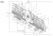
- the suction cup 23 is advantageously used for the rotation, by the suction cup 15, of a sheet 2a of reduced size, as schematically shown with a dashed line in Figure 3 .
- the suction cup 23 supports the sheet 2a whilst waiting that the suction cup 15 lifts along Y to pick up again the sheet 2 in a more advantageous position than the lower edge by the very nature of the reduced size of the sheet 2a.
- the pickup device 23 is installed on the carriage 11 and forms the above-mentioned pickup device 22.
- the machine 1 also comprises a supporting system, schematically illustrated with a block 24, for sheets 2 with a rectangular shape, that is, not polygonal or with curvilinear edges.
- the system 24 is associated with the frame 4 and is formed for example by a template or by a series of pins which allow the resting of a sheet 2 having any shape.
- the sheet 2 can be moved forward as described above as far as the suction cup 15.
- the suction cup 15 picks up the sheet 2 and thanks to the possibility of rotation about the axis of rotation R and the possibility of translating along the direction Y, suitably interpolated, by the unit 16, allows the machine 1 to perform machining operations also on edges for example curved.
- the proposed solution is faster as tool changes are not necessary for polishing the edge; once the edge to be machined is positioned, if necessary by suitable rotations of the shaft, the train of grinding wheels, which carries all the grinding wheels necessary for the machining operations, performs the machining for each edge after the respective rotations.
- the automatic rotation of the sheet not only increases productivity but also makes the machine safer than prior art solutions as the rotation of the sheet is not performed manually by an operator who would be in a danger zone.
- the presence of the supporting system in combination with the rotary axis suitably controlled in combination with the tools allows performance of the machining operations also on sheets having edges which are not rectilinear, for example curved, that is, it renders the machine more versatile and not limited to machining operations on square or rectangular sheets.
Landscapes
- Engineering & Computer Science (AREA)
- Mechanical Engineering (AREA)
- Chemical & Material Sciences (AREA)
- Ceramic Engineering (AREA)
- Inorganic Chemistry (AREA)
- Grinding And Polishing Of Tertiary Curved Surfaces And Surfaces With Complex Shapes (AREA)
- Grinding Of Cylindrical And Plane Surfaces (AREA)
- Lubricants (AREA)
Applications Claiming Priority (1)
| Application Number | Priority Date | Filing Date | Title |
|---|---|---|---|
| IT000005A ITRN20130005A1 (it) | 2013-01-31 | 2013-01-31 | Macchina utensile. |
Publications (2)
| Publication Number | Publication Date |
|---|---|
| EP2762273A1 true EP2762273A1 (de) | 2014-08-06 |
| EP2762273B1 EP2762273B1 (de) | 2015-12-02 |
Family
ID=47790361
Family Applications (1)
| Application Number | Title | Priority Date | Filing Date |
|---|---|---|---|
| EP14153130.1A Not-in-force EP2762273B1 (de) | 2013-01-31 | 2014-01-29 | Werkzeugmaschine |
Country Status (2)
| Country | Link |
|---|---|
| EP (1) | EP2762273B1 (de) |
| IT (1) | ITRN20130005A1 (de) |
Cited By (7)
| Publication number | Priority date | Publication date | Assignee | Title |
|---|---|---|---|---|
| ITUB20155709A1 (it) * | 2015-11-18 | 2017-05-18 | Biesse Spa | Macchina per lavorare lastre in posizione sostanzialmente verticale, con utensile di molatura a tazza che e' orientabile intorno ad un asse ortogonale al piano della lastra |
| IT201700110165A1 (it) * | 2017-10-02 | 2019-04-02 | Denver Spa | Macchina utensile |
| IT201800003968A1 (it) * | 2018-03-26 | 2019-09-26 | Bottero Spa | Metodo e impianto di molatura per la molatura di un articolo di vetro piano |
| IT201800009216A1 (it) * | 2018-10-05 | 2020-04-05 | Bottero Spa | Macchina rettilinea di molatura di una lastra di vetro |
| IT202000022276A1 (it) * | 2020-09-22 | 2022-03-22 | Antonio Piazza | Isola di lavorazione compatta per il prelievo di prodotto lastriforme da magazzino e l’invio dopo rotazione dello stesso alla linea di lavorazione |
| IT202200015081A1 (it) * | 2022-07-19 | 2024-01-19 | Forel S P A Unipersonale | Procedimento e apparato per trattenere ed eseguire lavorazioni su una lastra |
| EP4335604A3 (de) * | 2022-09-09 | 2024-07-17 | Denver S.p.A. | Vorrichtung zum halten und referenzieren von bogen in vertikaler lage und system |
Families Citing this family (2)
| Publication number | Priority date | Publication date | Assignee | Title |
|---|---|---|---|---|
| CN111546524A (zh) * | 2020-04-10 | 2020-08-18 | 大族激光科技产业集团股份有限公司 | 一种全自动上下料智能cnc加工设备 |
| CN111633582A (zh) * | 2020-05-25 | 2020-09-08 | 吴玮 | 一种钢化玻璃制作生产预处理用固定工具及固定方法 |
Citations (2)
| Publication number | Priority date | Publication date | Assignee | Title |
|---|---|---|---|---|
| EP0769348A1 (de) * | 1995-10-20 | 1997-04-23 | FOR.EL. BASE di VIANELLO FORTUNATO & C. S.n.c. | Verfahren und Vorrichtung zum Entfernen von Beschichtungen aus der Oberfläche einer Glasplatte |
| WO2011016098A1 (ja) * | 2009-08-07 | 2011-02-10 | 坂東機工株式会社 | ガラス板の加工方法及びガラス板の加工装置 |
-
2013
- 2013-01-31 IT IT000005A patent/ITRN20130005A1/it unknown
-
2014
- 2014-01-29 EP EP14153130.1A patent/EP2762273B1/de not_active Not-in-force
Patent Citations (2)
| Publication number | Priority date | Publication date | Assignee | Title |
|---|---|---|---|---|
| EP0769348A1 (de) * | 1995-10-20 | 1997-04-23 | FOR.EL. BASE di VIANELLO FORTUNATO & C. S.n.c. | Verfahren und Vorrichtung zum Entfernen von Beschichtungen aus der Oberfläche einer Glasplatte |
| WO2011016098A1 (ja) * | 2009-08-07 | 2011-02-10 | 坂東機工株式会社 | ガラス板の加工方法及びガラス板の加工装置 |
Cited By (11)
| Publication number | Priority date | Publication date | Assignee | Title |
|---|---|---|---|---|
| ITUB20155709A1 (it) * | 2015-11-18 | 2017-05-18 | Biesse Spa | Macchina per lavorare lastre in posizione sostanzialmente verticale, con utensile di molatura a tazza che e' orientabile intorno ad un asse ortogonale al piano della lastra |
| EP3170622A1 (de) | 2015-11-18 | 2017-05-24 | Biesse S.p.A. | Maschine zum bearbeiten von platten in einer im wesentlichen vertikalen position, mit einem schalenschleifwerkzeug, das rund um eine orthogonalachse ausrichtbar ist |
| IT201700110165A1 (it) * | 2017-10-02 | 2019-04-02 | Denver Spa | Macchina utensile |
| IT201800003968A1 (it) * | 2018-03-26 | 2019-09-26 | Bottero Spa | Metodo e impianto di molatura per la molatura di un articolo di vetro piano |
| EP3546120A1 (de) * | 2018-03-26 | 2019-10-02 | Bottero S.p.A. | Verfahren und schleifanlage zum schleifen eines flachen glasartikels |
| IT201800009216A1 (it) * | 2018-10-05 | 2020-04-05 | Bottero Spa | Macchina rettilinea di molatura di una lastra di vetro |
| EP3632614A1 (de) * | 2018-10-05 | 2020-04-08 | Bottero S.p.A. | Werkzeugmaschine |
| IT202000022276A1 (it) * | 2020-09-22 | 2022-03-22 | Antonio Piazza | Isola di lavorazione compatta per il prelievo di prodotto lastriforme da magazzino e l’invio dopo rotazione dello stesso alla linea di lavorazione |
| IT202200015081A1 (it) * | 2022-07-19 | 2024-01-19 | Forel S P A Unipersonale | Procedimento e apparato per trattenere ed eseguire lavorazioni su una lastra |
| WO2024018495A1 (en) * | 2022-07-19 | 2024-01-25 | Forel S.p.a. | Method and apparatus for holding and performing work on a sheet |
| EP4335604A3 (de) * | 2022-09-09 | 2024-07-17 | Denver S.p.A. | Vorrichtung zum halten und referenzieren von bogen in vertikaler lage und system |
Also Published As
| Publication number | Publication date |
|---|---|
| ITRN20130005A1 (it) | 2014-08-01 |
| EP2762273B1 (de) | 2015-12-02 |
Similar Documents
| Publication | Publication Date | Title |
|---|---|---|
| EP2762273B1 (de) | Werkzeugmaschine | |
| US20180250781A1 (en) | Autonomous production line | |
| JP6195032B2 (ja) | ガラス板の加工装置 | |
| EP3342535B1 (de) | Glasplattenbearbeitungsvorrichtung | |
| US9358653B2 (en) | Double-spindle machining apparatus | |
| EP3170622A1 (de) | Maschine zum bearbeiten von platten in einer im wesentlichen vertikalen position, mit einem schalenschleifwerkzeug, das rund um eine orthogonalachse ausrichtbar ist | |
| CN113787226A (zh) | 一种多方向、多工位切槽生产线及其工作方法 | |
| CN110936024A (zh) | 一种精雕机 | |
| CN109746690B (zh) | 窗框自动化生产线 | |
| KR101804871B1 (ko) | 금속 판재용 삼면 면취 가공장치 | |
| KR20170069703A (ko) | 복합형 시앤시 공작기계용 작업테이블 | |
| JP2009527367A (ja) | 形削り盤 | |
| JP6195009B2 (ja) | ガラス板加工装置 | |
| WO2016142822A1 (en) | Apparatus for processing of glass plates | |
| JP6708826B2 (ja) | ガラス板加工装置 | |
| JP6194983B2 (ja) | ガラス板の加工装置 | |
| CN207156187U (zh) | 一种全自动直边倒角抛光机 | |
| CN223876789U (zh) | 一种双刀座磨床 | |
| JP2017031041A5 (de) | ||
| JP6643731B2 (ja) | ガラス板の加工装置 | |
| CN111318926A (zh) | 一种车刀研磨砂轮修整设备 | |
| CN121514917A (zh) | 一种楔形垫块自动加工生产线及自动加工方法 | |
| JP2006160604A (ja) | ガラス板の加工装置 |
Legal Events
| Date | Code | Title | Description |
|---|---|---|---|
| PUAI | Public reference made under article 153(3) epc to a published international application that has entered the european phase |
Free format text: ORIGINAL CODE: 0009012 |
|
| 17P | Request for examination filed |
Effective date: 20140129 |
|
| AK | Designated contracting states |
Kind code of ref document: A1 Designated state(s): AL AT BE BG CH CY CZ DE DK EE ES FI FR GB GR HR HU IE IS IT LI LT LU LV MC MK MT NL NO PL PT RO RS SE SI SK SM TR |
|
| AX | Request for extension of the european patent |
Extension state: BA ME |
|
| R17P | Request for examination filed (corrected) |
Effective date: 20150205 |
|
| RBV | Designated contracting states (corrected) |
Designated state(s): AL AT BE BG CH CY CZ DE DK EE ES FI FR GB GR HR HU IE IS IT LI LT LU LV MC MK MT NL NO PL PT RO RS SE SI SK SM TR |
|
| GRAP | Despatch of communication of intention to grant a patent |
Free format text: ORIGINAL CODE: EPIDOSNIGR1 |
|
| INTG | Intention to grant announced |
Effective date: 20150605 |
|
| RIN1 | Information on inventor provided before grant (corrected) |
Inventor name: FABBRI, ADOLFO |
|
| GRAS | Grant fee paid |
Free format text: ORIGINAL CODE: EPIDOSNIGR3 |
|
| GRAA | (expected) grant |
Free format text: ORIGINAL CODE: 0009210 |
|
| AK | Designated contracting states |
Kind code of ref document: B1 Designated state(s): AL AT BE BG CH CY CZ DE DK EE ES FI FR GB GR HR HU IE IS IT LI LT LU LV MC MK MT NL NO PL PT RO RS SE SI SK SM TR |
|
| REG | Reference to a national code |
Ref country code: GB Ref legal event code: FG4D |
|
| REG | Reference to a national code |
Ref country code: AT Ref legal event code: REF Ref document number: 763405 Country of ref document: AT Kind code of ref document: T Effective date: 20151215 Ref country code: CH Ref legal event code: EP |
|
| REG | Reference to a national code |
Ref country code: IE Ref legal event code: FG4D |
|
| REG | Reference to a national code |
Ref country code: DE Ref legal event code: R096 Ref document number: 602014000488 Country of ref document: DE |
|
| REG | Reference to a national code |
Ref country code: FR Ref legal event code: PLFP Year of fee payment: 3 |
|
| REG | Reference to a national code |
Ref country code: NL Ref legal event code: MP Effective date: 20160302 |
|
| REG | Reference to a national code |
Ref country code: LT Ref legal event code: MG4D |
|
| REG | Reference to a national code |
Ref country code: AT Ref legal event code: MK05 Ref document number: 763405 Country of ref document: AT Kind code of ref document: T Effective date: 20151202 |
|
| PG25 | Lapsed in a contracting state [announced via postgrant information from national office to epo] |
Ref country code: LT Free format text: LAPSE BECAUSE OF FAILURE TO SUBMIT A TRANSLATION OF THE DESCRIPTION OR TO PAY THE FEE WITHIN THE PRESCRIBED TIME-LIMIT Effective date: 20151202 Ref country code: NO Free format text: LAPSE BECAUSE OF FAILURE TO SUBMIT A TRANSLATION OF THE DESCRIPTION OR TO PAY THE FEE WITHIN THE PRESCRIBED TIME-LIMIT Effective date: 20160302 Ref country code: ES Free format text: LAPSE BECAUSE OF FAILURE TO SUBMIT A TRANSLATION OF THE DESCRIPTION OR TO PAY THE FEE WITHIN THE PRESCRIBED TIME-LIMIT Effective date: 20151202 |
|
| PG25 | Lapsed in a contracting state [announced via postgrant information from national office to epo] |
Ref country code: AT Free format text: LAPSE BECAUSE OF FAILURE TO SUBMIT A TRANSLATION OF THE DESCRIPTION OR TO PAY THE FEE WITHIN THE PRESCRIBED TIME-LIMIT Effective date: 20151202 Ref country code: LV Free format text: LAPSE BECAUSE OF FAILURE TO SUBMIT A TRANSLATION OF THE DESCRIPTION OR TO PAY THE FEE WITHIN THE PRESCRIBED TIME-LIMIT Effective date: 20151202 Ref country code: BE Free format text: LAPSE BECAUSE OF NON-PAYMENT OF DUE FEES Effective date: 20160131 Ref country code: RS Free format text: LAPSE BECAUSE OF FAILURE TO SUBMIT A TRANSLATION OF THE DESCRIPTION OR TO PAY THE FEE WITHIN THE PRESCRIBED TIME-LIMIT Effective date: 20151202 Ref country code: GR Free format text: LAPSE BECAUSE OF FAILURE TO SUBMIT A TRANSLATION OF THE DESCRIPTION OR TO PAY THE FEE WITHIN THE PRESCRIBED TIME-LIMIT Effective date: 20160303 Ref country code: SE Free format text: LAPSE BECAUSE OF FAILURE TO SUBMIT A TRANSLATION OF THE DESCRIPTION OR TO PAY THE FEE WITHIN THE PRESCRIBED TIME-LIMIT Effective date: 20151202 Ref country code: PL Free format text: LAPSE BECAUSE OF FAILURE TO SUBMIT A TRANSLATION OF THE DESCRIPTION OR TO PAY THE FEE WITHIN THE PRESCRIBED TIME-LIMIT Effective date: 20151202 Ref country code: FI Free format text: LAPSE BECAUSE OF FAILURE TO SUBMIT A TRANSLATION OF THE DESCRIPTION OR TO PAY THE FEE WITHIN THE PRESCRIBED TIME-LIMIT Effective date: 20151202 Ref country code: NL Free format text: LAPSE BECAUSE OF FAILURE TO SUBMIT A TRANSLATION OF THE DESCRIPTION OR TO PAY THE FEE WITHIN THE PRESCRIBED TIME-LIMIT Effective date: 20151202 |
|
| PG25 | Lapsed in a contracting state [announced via postgrant information from national office to epo] |
Ref country code: IS Free format text: LAPSE BECAUSE OF FAILURE TO SUBMIT A TRANSLATION OF THE DESCRIPTION OR TO PAY THE FEE WITHIN THE PRESCRIBED TIME-LIMIT Effective date: 20151202 |
|
| PG25 | Lapsed in a contracting state [announced via postgrant information from national office to epo] |
Ref country code: CZ Free format text: LAPSE BECAUSE OF FAILURE TO SUBMIT A TRANSLATION OF THE DESCRIPTION OR TO PAY THE FEE WITHIN THE PRESCRIBED TIME-LIMIT Effective date: 20151202 |
|
| PG25 | Lapsed in a contracting state [announced via postgrant information from national office to epo] |
Ref country code: RO Free format text: LAPSE BECAUSE OF FAILURE TO SUBMIT A TRANSLATION OF THE DESCRIPTION OR TO PAY THE FEE WITHIN THE PRESCRIBED TIME-LIMIT Effective date: 20151202 Ref country code: SK Free format text: LAPSE BECAUSE OF FAILURE TO SUBMIT A TRANSLATION OF THE DESCRIPTION OR TO PAY THE FEE WITHIN THE PRESCRIBED TIME-LIMIT Effective date: 20151202 Ref country code: PT Free format text: LAPSE BECAUSE OF FAILURE TO SUBMIT A TRANSLATION OF THE DESCRIPTION OR TO PAY THE FEE WITHIN THE PRESCRIBED TIME-LIMIT Effective date: 20160404 Ref country code: IS Free format text: LAPSE BECAUSE OF FAILURE TO SUBMIT A TRANSLATION OF THE DESCRIPTION OR TO PAY THE FEE WITHIN THE PRESCRIBED TIME-LIMIT Effective date: 20160402 Ref country code: EE Free format text: LAPSE BECAUSE OF FAILURE TO SUBMIT A TRANSLATION OF THE DESCRIPTION OR TO PAY THE FEE WITHIN THE PRESCRIBED TIME-LIMIT Effective date: 20151202 Ref country code: SM Free format text: LAPSE BECAUSE OF FAILURE TO SUBMIT A TRANSLATION OF THE DESCRIPTION OR TO PAY THE FEE WITHIN THE PRESCRIBED TIME-LIMIT Effective date: 20151202 Ref country code: LU Free format text: LAPSE BECAUSE OF FAILURE TO SUBMIT A TRANSLATION OF THE DESCRIPTION OR TO PAY THE FEE WITHIN THE PRESCRIBED TIME-LIMIT Effective date: 20160129 |
|
| REG | Reference to a national code |
Ref country code: DE Ref legal event code: R097 Ref document number: 602014000488 Country of ref document: DE |
|
| PG25 | Lapsed in a contracting state [announced via postgrant information from national office to epo] |
Ref country code: MC Free format text: LAPSE BECAUSE OF FAILURE TO SUBMIT A TRANSLATION OF THE DESCRIPTION OR TO PAY THE FEE WITHIN THE PRESCRIBED TIME-LIMIT Effective date: 20151202 |
|
| PLBE | No opposition filed within time limit |
Free format text: ORIGINAL CODE: 0009261 |
|
| STAA | Information on the status of an ep patent application or granted ep patent |
Free format text: STATUS: NO OPPOSITION FILED WITHIN TIME LIMIT |
|
| PG25 | Lapsed in a contracting state [announced via postgrant information from national office to epo] |
Ref country code: DK Free format text: LAPSE BECAUSE OF FAILURE TO SUBMIT A TRANSLATION OF THE DESCRIPTION OR TO PAY THE FEE WITHIN THE PRESCRIBED TIME-LIMIT Effective date: 20151202 |
|
| REG | Reference to a national code |
Ref country code: IE Ref legal event code: MM4A |
|
| 26N | No opposition filed |
Effective date: 20160905 |
|
| PG25 | Lapsed in a contracting state [announced via postgrant information from national office to epo] |
Ref country code: SI Free format text: LAPSE BECAUSE OF FAILURE TO SUBMIT A TRANSLATION OF THE DESCRIPTION OR TO PAY THE FEE WITHIN THE PRESCRIBED TIME-LIMIT Effective date: 20151202 |
|
| PG25 | Lapsed in a contracting state [announced via postgrant information from national office to epo] |
Ref country code: BE Free format text: LAPSE BECAUSE OF FAILURE TO SUBMIT A TRANSLATION OF THE DESCRIPTION OR TO PAY THE FEE WITHIN THE PRESCRIBED TIME-LIMIT Effective date: 20151202 |
|
| REG | Reference to a national code |
Ref country code: FR Ref legal event code: PLFP Year of fee payment: 4 |
|
| PG25 | Lapsed in a contracting state [announced via postgrant information from national office to epo] |
Ref country code: IE Free format text: LAPSE BECAUSE OF NON-PAYMENT OF DUE FEES Effective date: 20160129 |
|
| PG25 | Lapsed in a contracting state [announced via postgrant information from national office to epo] |
Ref country code: MT Free format text: LAPSE BECAUSE OF FAILURE TO SUBMIT A TRANSLATION OF THE DESCRIPTION OR TO PAY THE FEE WITHIN THE PRESCRIBED TIME-LIMIT Effective date: 20151202 |
|
| REG | Reference to a national code |
Ref country code: CH Ref legal event code: PL |
|
| PG25 | Lapsed in a contracting state [announced via postgrant information from national office to epo] |
Ref country code: LI Free format text: LAPSE BECAUSE OF NON-PAYMENT OF DUE FEES Effective date: 20170131 Ref country code: CH Free format text: LAPSE BECAUSE OF NON-PAYMENT OF DUE FEES Effective date: 20170131 |
|
| REG | Reference to a national code |
Ref country code: FR Ref legal event code: PLFP Year of fee payment: 5 |
|
| PG25 | Lapsed in a contracting state [announced via postgrant information from national office to epo] |
Ref country code: CY Free format text: LAPSE BECAUSE OF FAILURE TO SUBMIT A TRANSLATION OF THE DESCRIPTION OR TO PAY THE FEE WITHIN THE PRESCRIBED TIME-LIMIT Effective date: 20151202 Ref country code: HU Free format text: LAPSE BECAUSE OF FAILURE TO SUBMIT A TRANSLATION OF THE DESCRIPTION OR TO PAY THE FEE WITHIN THE PRESCRIBED TIME-LIMIT; INVALID AB INITIO Effective date: 20140129 |
|
| PG25 | Lapsed in a contracting state [announced via postgrant information from national office to epo] |
Ref country code: TR Free format text: LAPSE BECAUSE OF FAILURE TO SUBMIT A TRANSLATION OF THE DESCRIPTION OR TO PAY THE FEE WITHIN THE PRESCRIBED TIME-LIMIT Effective date: 20151202 Ref country code: MT Free format text: LAPSE BECAUSE OF FAILURE TO SUBMIT A TRANSLATION OF THE DESCRIPTION OR TO PAY THE FEE WITHIN THE PRESCRIBED TIME-LIMIT Effective date: 20160131 Ref country code: HR Free format text: LAPSE BECAUSE OF FAILURE TO SUBMIT A TRANSLATION OF THE DESCRIPTION OR TO PAY THE FEE WITHIN THE PRESCRIBED TIME-LIMIT Effective date: 20151202 Ref country code: MK Free format text: LAPSE BECAUSE OF FAILURE TO SUBMIT A TRANSLATION OF THE DESCRIPTION OR TO PAY THE FEE WITHIN THE PRESCRIBED TIME-LIMIT Effective date: 20151202 |
|
| PG25 | Lapsed in a contracting state [announced via postgrant information from national office to epo] |
Ref country code: BG Free format text: LAPSE BECAUSE OF FAILURE TO SUBMIT A TRANSLATION OF THE DESCRIPTION OR TO PAY THE FEE WITHIN THE PRESCRIBED TIME-LIMIT Effective date: 20151202 |
|
| PG25 | Lapsed in a contracting state [announced via postgrant information from national office to epo] |
Ref country code: AL Free format text: LAPSE BECAUSE OF FAILURE TO SUBMIT A TRANSLATION OF THE DESCRIPTION OR TO PAY THE FEE WITHIN THE PRESCRIBED TIME-LIMIT Effective date: 20151202 |
|
| PGFP | Annual fee paid to national office [announced via postgrant information from national office to epo] |
Ref country code: DE Payment date: 20200131 Year of fee payment: 7 Ref country code: IT Payment date: 20200130 Year of fee payment: 7 Ref country code: GB Payment date: 20200131 Year of fee payment: 7 |
|
| PGFP | Annual fee paid to national office [announced via postgrant information from national office to epo] |
Ref country code: FR Payment date: 20200130 Year of fee payment: 7 |
|
| REG | Reference to a national code |
Ref country code: DE Ref legal event code: R119 Ref document number: 602014000488 Country of ref document: DE |
|
| GBPC | Gb: european patent ceased through non-payment of renewal fee |
Effective date: 20210129 |
|
| PG25 | Lapsed in a contracting state [announced via postgrant information from national office to epo] |
Ref country code: FR Free format text: LAPSE BECAUSE OF NON-PAYMENT OF DUE FEES Effective date: 20210131 |
|
| PG25 | Lapsed in a contracting state [announced via postgrant information from national office to epo] |
Ref country code: GB Free format text: LAPSE BECAUSE OF NON-PAYMENT OF DUE FEES Effective date: 20210129 Ref country code: DE Free format text: LAPSE BECAUSE OF NON-PAYMENT OF DUE FEES Effective date: 20210803 |
|
| PG25 | Lapsed in a contracting state [announced via postgrant information from national office to epo] |
Ref country code: IT Free format text: LAPSE BECAUSE OF NON-PAYMENT OF DUE FEES Effective date: 20210129 |