EP2762354A2 - Personenkraftwagen und verstellbarer Sitz dafür - Google Patents
Personenkraftwagen und verstellbarer Sitz dafür Download PDFInfo
- Publication number
- EP2762354A2 EP2762354A2 EP14153725.8A EP14153725A EP2762354A2 EP 2762354 A2 EP2762354 A2 EP 2762354A2 EP 14153725 A EP14153725 A EP 14153725A EP 2762354 A2 EP2762354 A2 EP 2762354A2
- Authority
- EP
- European Patent Office
- Prior art keywords
- seat
- subframe
- passenger vehicle
- adjustable
- coupling structure
- Prior art date
- Legal status (The legal status is an assumption and is not a legal conclusion. Google has not performed a legal analysis and makes no representation as to the accuracy of the status listed.)
- Withdrawn
Links
- 230000008878 coupling Effects 0.000 claims description 36
- 238000010168 coupling process Methods 0.000 claims description 36
- 238000005859 coupling reaction Methods 0.000 claims description 36
- 239000000725 suspension Substances 0.000 claims description 14
- 230000008901 benefit Effects 0.000 description 11
- 239000004744 fabric Substances 0.000 description 5
- 210000001364 upper extremity Anatomy 0.000 description 3
- 229910000831 Steel Inorganic materials 0.000 description 1
- 230000009471 action Effects 0.000 description 1
- 230000008859 change Effects 0.000 description 1
- 238000009434 installation Methods 0.000 description 1
- 230000004048 modification Effects 0.000 description 1
- 238000012986 modification Methods 0.000 description 1
- 230000035939 shock Effects 0.000 description 1
- 239000010959 steel Substances 0.000 description 1
Images


Classifications
-
- A—HUMAN NECESSITIES
- A47—FURNITURE; DOMESTIC ARTICLES OR APPLIANCES; COFFEE MILLS; SPICE MILLS; SUCTION CLEANERS IN GENERAL
- A47C—CHAIRS; SOFAS; BEDS
- A47C17/00—Sofas; Couches; Beds
- A47C17/04—Seating furniture, e.g. sofas, couches, settees, or the like, with movable parts changeable to beds; Chair beds
- A47C17/16—Seating furniture changeable to beds by tilting or pivoting the back-rest
- A47C17/17—Seating furniture changeable to beds by tilting or pivoting the back-rest with coupled movement of back-rest and seat
-
- A—HUMAN NECESSITIES
- A47—FURNITURE; DOMESTIC ARTICLES OR APPLIANCES; COFFEE MILLS; SPICE MILLS; SUCTION CLEANERS IN GENERAL
- A47C—CHAIRS; SOFAS; BEDS
- A47C17/00—Sofas; Couches; Beds
- A47C17/04—Seating furniture, e.g. sofas, couches, settees, or the like, with movable parts changeable to beds; Chair beds
- A47C17/34—Joining seats, chairs, or couches to form beds
-
- B—PERFORMING OPERATIONS; TRANSPORTING
- B60—VEHICLES IN GENERAL
- B60N—SEATS SPECIALLY ADAPTED FOR VEHICLES; VEHICLE PASSENGER ACCOMMODATION NOT OTHERWISE PROVIDED FOR
- B60N2/00—Seats specially adapted for vehicles; Arrangement or mounting of seats in vehicles
- B60N2/02—Seats specially adapted for vehicles; Arrangement or mounting of seats in vehicles the seat or part thereof being movable, e.g. adjustable
- B60N2/04—Seats specially adapted for vehicles; Arrangement or mounting of seats in vehicles the seat or part thereof being movable, e.g. adjustable the whole seat being movable
-
- B—PERFORMING OPERATIONS; TRANSPORTING
- B60—VEHICLES IN GENERAL
- B60N—SEATS SPECIALLY ADAPTED FOR VEHICLES; VEHICLE PASSENGER ACCOMMODATION NOT OTHERWISE PROVIDED FOR
- B60N2/00—Seats specially adapted for vehicles; Arrangement or mounting of seats in vehicles
- B60N2/24—Seats specially adapted for vehicles; Arrangement or mounting of seats in vehicles for particular purposes or particular vehicles
- B60N2/32—Seats specially adapted for vehicles; Arrangement or mounting of seats in vehicles for particular purposes or particular vehicles convertible for other use
- B60N2/34—Seats specially adapted for vehicles; Arrangement or mounting of seats in vehicles for particular purposes or particular vehicles convertible for other use into a bed
Definitions
- the present invention relates to an improved passenger vehicle and an adjustable seat which can be turned from a seat into a bed.
- buses or double-decker buses are often equipped with adjustable seats which can be converted to a sleeping position. These seats are then turned into beds in order to achieve maximum capacity in both the sleeping and sitting configuration.
- a problem with adjustable seats in vehicles is the inadequate seating comfort and sleeping comfort of passengers.
- Safety is also a problem, since passengers in a sleeping position are more vulnerable when subjected to unexpected and abrupt movements or shocks during a journey.
- the invention relates in particular to an adjustable seat for a passenger vehicle, which seat is provided with a frame which comprises a back subframe provided with a backrest cushion, a seat subframe provided with a seat cushion and a fastening subframe, wherein the fastening subframe is suitable for mutually fastening the back subframe to the seat subframe, and/or is suitable for fastening one of the back subframe and seat subframe, or both, to a floor of the passenger vehicle, which frame can be adjusted between a seating position and a sleeping position, wherein the upper side of the seat cushion in the sleeping position is situated below the upper side of the seat cushion in the seating position, as defined in Claim 1.
- the invention in a second aspect, relates to a passenger vehicle provided with at least one compartment which is provided with one, two, three or more pairs of adjustable seats, as defined in Claim 11.
- a seat means one or more than one seat.
- the invention relates to an adjustable seat for a passenger vehicle (40), which seat is provided with a frame which comprises a back subframe (3) provided with a backrest cushion, a seat subframe provided with a seat cushion and a fastening subframe, wherein the fastening subframe is suitable for mutually attaching the back subframe to the seat subframe, and/or is suitable for attaching one of the back subframe and seat subframe, or both, to a floor of the passenger vehicle, which frame can be adjusted between a seating position and a sleeping position, wherein the sleeping position is lower than the seat cushion in the seating position.
- the term "seating position" refers to a position of the adjustable seat in which a person can sit on the seat cushion and can lean against the backrest cushion of said seat at the same time.
- the term "sleeping position” refers to a position of the adjustable seat in which a person can lie on both the seat cushion and the backrest cushion of said seat.
- the fact that the sleeping position is situated at a lower level than the seating position offers the advantage that passengers will sleep closer to the floor.
- the height in a passenger vehicle is limited.
- the height in a passenger vehicle is often limited even further by, for example, overhead sleeping systems which are installed (e.g. installation of additional suspended bed(s)) or the use of two floors in a double-decker bus.
- the present invention creates additional vertical space when the seat is in the sleeping position, so that the space in the passenger vehicle can be used more efficiently. This also offers the advantage of improved sleeping comfort for the passengers. The confined or claustrophobic feeling will lessen.
- the seat subframe in the sleeping position extends below the seat subframe in the seating position.
- the seat subframe extends substantially horizontally in both positions.
- the back subframe and the seat subframe are in the same horizontal plane in the sleeping position, thus providing the required lying and sleeping comfort for the passenger.
- the back subframe and the seat subframe enclose an angle of between 80° and 120°, preferably between 90° and 115°, more preferably between 100° and 110° and most preferably of approximately 109°, in the seating position, thus providing the required seating comfort for the passenger.
- the seating side of the seat cushion extends substantially horizontally in both positions, thus providing the required lying and sleeping comfort for the passenger.
- the leaning side of the backrest cushion and the seating side of the seat cushion extend in the same horizontal plane in the sleeping position.
- the leaning side of the backrest cushion and the seating side of the seat cushion enclose an angle of between 80° and 120°, preferably between 90° and 110°, more preferably approximately 100°, in the seating position, thus providing the required seating comfort for the passenger.
- the fastening subframe comprises a four-rod system, wherein the four-rod system comprises four coupling structures and wherein one coupling structure is mounted to the floor and a second coupling structure concerns the seat subframe.
- the term "four-rod system” is understood to mean a device which comprises four coupling structures, wherein a first coupling structure is securely mounted to the floor and wherein three other coupling structures are pivotably beared with respect to each other and the first coupling structure in such a way that these three coupling structures can move.
- the seat can be adjusted more easily and more quickly, as a result of which adjustment can take place while driving and a time saving is achieved.
- the fastening subframe comprises a second rod system, wherein a first coupling structure is mounted to the floor, a second coupling structure is beared on the first coupling structure and on a third coupling structure, which relates to the back subframe.
- the seat can be adjusted more easily and more quickly, as a result of which adjustment can take place while driving and a time saving is achieved.
- the fastening subframe comprises a coupling structure which is pivotably beared on a coupling structure of the four-rod system and is pivotably beared on a coupling structure of the second rod system.
- the seat subframe and the back subframe can be displaced together in a simple and smooth manner between two positions.
- the seat can be adjusted more easily and more quickly, as a result of which adjustment can be effected by one movement while driving. Therefore, the vehicle does not have to be stationary, but can continue to drive while the seats are being changed from their seating position to their sleeping position or vice versa. This not only results in a time saving, but also in an economic advantage.
- a coupling structure of the second rod system is connected to the floor via a gas spring.
- gas spring refers to a cylinder with a piston, in which gas in the cylinder is compressed and thus provides a spring action.
- This may be a pneumatic spring or a gas tension spring.
- a pneumatic spring requires manual force to push the gas spring in, a gas tension spring requires manual force to push it out.
- the seat is provided with a locking system which is suitable to lock the second rod system in the seating position.
- locking system refers to a system which is suitable to fix or lock the position of the adjustable seat.
- An example thereof is the combination of a "two-rotor latch” and a “striker” bolt.
- said locking system can be unlocked by means of a switch.
- said locking system can be unlocked by means of a lever at the front of the seat, situated below the seat cushion and incorporated into the seat subframe.
- the seat is provided with a second locking system which is suitable to lock the back subframe in the seating position.
- the back subframe may be clamped against the wall in the seating position by means of, for example, a hook-clasp system. This results in a seat which is more secure and robust.
- the fastening subframe comprises a bottom frame which connects the fastening subframe to the floor of the passenger vehicle.
- This bottom frame is preferably composed of a steel structure. This offers the advantage of a more robust and fixed arrangement of the seat in a passenger vehicle.
- the back subframe is beared on said seat subframe.
- a coupling structure of said four-rod system is connected to the bottom frame via a gas spring.
- the seat is provided with a locking system which is suitable to lock said four-rod system in the seating position.
- said locking system can be unlocked by means of a switch.
- said locking system can be unlocked by means of a lever at the front of the seat, situated below the seat cushion and incorporated into the seat subframe.
- a third coupling structure of said four-rod system and/or said seat subframe is provided with a supporting leg, comprising a flat plate, which plate is suitable to make flat contact with said floor in the sleeping position and/or seat position.
- a third coupling structure of said four-rod system and/or said seat subframe is provided with a supporting leg, comprising a flat plate, which plate is suitable to make flat contact with said floor in the sleeping position.
- the invention in a second aspect, relates to a passenger vehicle provided with at least one compartment which is provided with one, two, three or more pairs of adjustable seats, wherein said pairs of seats are attached to the floor in such a manner that each pair of seats together forms a bed in the sleeping position.
- the term "passenger vehicle” refers to a transport means for passengers in which these passengers can sit on seats. Examples are, inter alia, buses, double-decker buses and trains.
- the combination of two seats which together form a bed ensures that these erected beds are sufficiently long, so that the comfort for the passenger is increased.
- the seats do not have to be changed in the entire passenger vehicle at once, but can be changed per compartment.
- a compartment is provided with at least two orthogonal walls which are erected on the floor, which walls are situated at the foot ends and head ends of said at least one, two, three or more beds.
- suspension points are provided on said walls which are suitable to suspend at least one suspended bed between said walls of a compartment.
- the term "suspended bed” refers to a bed or a mat which can temporarily be arranged or suspended from said suspension points. In principle, it refers to both a stiff and a flexible structure.
- suspended beds ensures that the interior space of a passenger vehicle is used more efficiently. In this way, more passengers can recline or sleep in a passenger vehicle, thus yielding an security device.
- the suspension points are provided with a safety catch.
- the term "security device” refers to a device which ensures that a suspended bed is locked or secured. As sudden and abrupt movements may occur while travelling, this has the advantage that a suspended bed which is secured with a security device is safer and more comfortable, and cannot break free from the suspension and thus does not fall onto the person situated underneath.
- the walls of a compartment are provided with detachable head rests or head cushions.
- the mutual distance between two walls of a compartment can be limited, while the seating position offers sufficient comfort due to the fact that the cushion acts as an extension of the backrest.
- the mutual distance between the walls is between 1.80m and 2.00m, more preferably between 1.85m and 2.05m, most preferably between 1.90m and 2.00m. This results in a more efficient use of the space in the passenger vehicle.
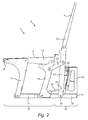
- Figs. 1 and 2 respectively show a perspective view and a side view of the frame (2) of an adjustable seat (1) in the seating position according to a preferred embodiment of the present invention.
- the frame (2) is provided with a back subframe (3) and a seat subframe (4), which, in the final adjustable seat, are provided with a backrest cushion (6) and a seat cushion (7), respectively.
- the frame (2) also comprises a fastening subframe (5) which is suitable to attach both the seat subframe (4) and the back subframe (3) to a floor of a passenger vehicle (40) and which connects the back subframe (3) and the seat subframe (4) to one another.
- the fastening subframe (5) comprises a four-rod system (10) which comprises the following four coupling structures: the front leg (12), the centre leg (14), the bottom frame (11, 38, 26, 21) and the seat subframe (13, 4).
- the bottom frame (11, 38) is mounted to the floor of the passenger vehicle (40).
- the fastening subframe (5) also comprises a second rod system which comprises the following three coupling structures: the rear leg (22), the bottom frame (21, 38) and the back subframe (23, 3).
- the bottom frame (38) comprises the rear subframe (26).
- the fastening subframe (5) furthermore also comprises a connecting leg (25) which is pivotably beared on the centre leg (14) and on the rear leg (22).
- the rear leg (22) is connected to the floor via a gas spring (34) (via a pin (35)). By rotating the rear leg around pivot pin (33), it is possible to move the second rod system in such a manner that the back subframe (3) moves along with it.
- the frame (2) can be adjusted between a seating position (8) and a sleeping position (9), with the sleeping position (9) being situated below the seating position (8).
- Fig. 3 shows a perspective view of the frame (2) after it has been changed to the sleeping position (9).
- Rubber (37) is provided on the rear subframe (26).
- the back subframe (3) rests on the bottom frame (11, 38, 26, 21) via the rubber (37). Due to the fact that the rubber between these two frames will stretch, many vibrations and much of the noise which is associated with travelling in a passenger vehicle (e.g. as a result of traffic islands) will be dampened by the rubber (37), thus improving the comfort of the passengers.
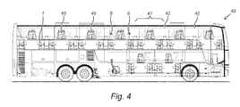
- Fig. 4 shows a side view of a double-decker bus (40) along its longitudinal axis.
- Both the upper deck and the lower deck comprise compartments (41) which are delimited by walls (42).
- a compartment (41) contains adjustable seats (1) and additionally also fold-away tables (45).
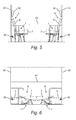
- Figs. 5 and 6 show a side view of a compartment (41) of a passenger vehicle with a pair of adjustable seats in the seating position and in the sleeping position, respectively.
- the backrest cushions (6) and the seat cushions (7) are also shown.
- the walls (42) of the compartment are provided with detachable head rests or head cushions (50). These can be click-fitted to the walls (42) to serve as an extension of the backrest cushion of the adjustable seat (1). In the sleeping position, they are removed from the walls (42) and stowed away.
- Figs. 7 and 8 show a top view of two preferred embodiments of a part of a passenger vehicle.
- the adjustable seats are in the seating position and two compartments are shown with the aisle running in between.
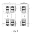
- Fig. 9 is a sectional view along the axis AA, as illustrated in Fig. 7 .
- the frames of the corresponding adjustable seats are shown, together with the suspension points (43) in the walls (42).
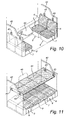
- Fig. 10 is a perspective view of a compartment of a passenger vehicle with four adjustable seats in the seating position.
- Fig. 11 is a perspective view of a compartment of a passenger vehicle with four adjustable seats in the sleeping position.
- a bed (44) is suspended from the suspension points (43).
- Fig. 12 shows a perspective view of another compartment of a passenger vehicle with four adjustable seats in the seating position.
- the walls (42) are provided with six suspension points (43).
- Fig. 13 shows a perspective view of the compartment of Fig. 12 with said adjustable seats in the sleeping position.
- Three rods (46) are provided between said six suspension points (43).
- a cloth (47) is provided to said rods (46), such that if said rods (46) are suspended between said suspension points, the cloth is tenser and forms two beds (44).
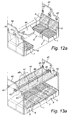
- Fig. 12a shows a perspective view of an alternative compartment of a passenger vehicle with four adjustable seats in the seating position.
- the walls (42) are provided with eight suspension points (43).
- Fig. 13a shows a perspective view of the compartment of Fig. 12a with four adjustable seats in the sleeping position.
- Four rods (46) are provided between said eight suspension points (43).
- a cloth (47) is provided between a pair of rods (46). If a pair of rods (46) is suspended between said suspension points (43), the cloth is tenser and forms a bed (44).
- a mattress can be provided on top of said these rods (46) and cloth (47).
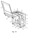
- Fig. 14 and 15 show respectively a more frontal and more rear perspective view of the frame (2) of an alternative adjustable seat (1) in the seating position according to a preferred embodiment of the present invention.
- the frame (2) is provided with a back subframe (3) and a seat subframe (4), which, in the final adjustable seat, are provided with a backrest cushion (6) and a seat cushion (7), respectively.
- the frame (2) also comprises a fastening subframe (5) which is suitable to attach the seat subframe (4) to a floor of a passenger vehicle (40).
- the fastening subframe (5) comprises a four-rod system (10) which comprises the following four coupling structures: the front leg (12), the centre leg (14), the bottom frame (11) and the seat subframe (13, 4).
- the bottom frame (11) is mounted to the floor of the passenger vehicle (40).
- the back subframe (3) is beared on said seat subframe (13) of said four-rod system (10).
- the bottom frame (11) comprises a rear subframe (57).
- the front leg (12) of said four-rod system (10) is provided with a supporting leg (50).
- Said seat subframe (4) is also provided with supporting legs (51, 52).
- These supporting legs (50, 51, 52) comprise a flat plate, which plate (50) is suitable to make flat contact with the floor in the sleeping position (9).
- the rear leg (14) is connected to the rear subframe (57) via a gas spring (34). By rotating the rear leg around pivot pin (56), it is possible to move the four-rod system (10) in such a manner that the back subframe (3) moves along with it.
- the frame (2) can be adjusted between a seating position (8) and a sleeping position (9), with the sleeping position (9) being situated below the seating position (8).
- Fig. 16 shows a side view of a compartment of a passenger vehicle with a pair of adjustable seats in the sleeping position.
- the left seat concerns an adjustable seat (1) as illustrated in Fig. 1 , i.e. in sleeping position.
- the right seat concerns the same adjustable seat (1) as in Figs. 14 and 15 , but now changed into the sleeping position (9).
- a passenger vehicle (40) typically, non-flat areas exist in a passenger vehicle (40) due to obstacles, e.g. near the centre stairs or in the rear of the vehicle (40).
- the seat subframe (4) rests on the elevated 'step' (58) of the floor in seating position (8) via its supporting legs (52).
- the back subframe (3) rests on the step (58) of the floor.
Landscapes
- Engineering & Computer Science (AREA)
- Aviation & Aerospace Engineering (AREA)
- Transportation (AREA)
- Mechanical Engineering (AREA)
- Health & Medical Sciences (AREA)
- General Health & Medical Sciences (AREA)
- Nursing (AREA)
- Seats For Vehicles (AREA)
- Passenger Equipment (AREA)
Applications Claiming Priority (1)
| Application Number | Priority Date | Filing Date | Title |
|---|---|---|---|
| BE201300070A BE1020730A3 (nl) | 2013-02-04 | 2013-02-04 | Inrichting van een zitrijtuig en verstelbare zetel hiervoor. |
Publications (2)
| Publication Number | Publication Date |
|---|---|
| EP2762354A2 true EP2762354A2 (de) | 2014-08-06 |
| EP2762354A3 EP2762354A3 (de) | 2018-01-10 |
Family
ID=48087322
Family Applications (1)
| Application Number | Title | Priority Date | Filing Date |
|---|---|---|---|
| EP14153725.8A Withdrawn EP2762354A3 (de) | 2013-02-04 | 2014-02-03 | Personenkraftwagen und verstellbarer Sitz dafür |
Country Status (4)
| Country | Link |
|---|---|
| US (1) | US9629471B2 (de) |
| EP (1) | EP2762354A3 (de) |
| BE (1) | BE1020730A3 (de) |
| CA (1) | CA2841651C (de) |
Cited By (1)
| Publication number | Priority date | Publication date | Assignee | Title |
|---|---|---|---|---|
| FR3064556A1 (fr) * | 2017-04-04 | 2018-10-05 | Stelia Aerospace | Fauteuil pour passager de vehicule comportant une configuration repos |
Families Citing this family (9)
| Publication number | Priority date | Publication date | Assignee | Title |
|---|---|---|---|---|
| US10787262B2 (en) * | 2017-09-05 | 2020-09-29 | Textron Innovations, Inc. | Modular seat |
| CN108669896B (zh) * | 2018-04-19 | 2023-11-21 | 张杰卡 | 一种用于午休的可折叠学生课桌 |
| US10556524B1 (en) * | 2018-08-29 | 2020-02-11 | Premier Products, Inc. | Vehicle sofa-bed and method of use |
| KR102112925B1 (ko) * | 2018-08-29 | 2020-05-19 | 최택열 | 차량에 장착되는 가변형 좌석 |
| US12545155B2 (en) | 2018-08-29 | 2026-02-10 | Premier Products, Inc. | VAN/RV lay-flat sofa-bed and method of use |
| US11685303B2 (en) | 2018-08-31 | 2023-06-27 | Daniel R. Brettschneider | Berth apparatus and methods using physiological parameters for controlling berth motion to promote relaxation and to induce sleep |
| AU2020235850B2 (en) | 2019-03-11 | 2022-08-25 | Storyteller Overland, Llc | Rv retrofit system |
| JP7051140B2 (ja) * | 2020-07-22 | 2022-04-11 | 保 上野 | 旅客機の座席システム |
| US11820275B2 (en) | 2020-10-30 | 2023-11-21 | Daniel R. Brettschneider | Carrier platform with suspension mechanism for supporting a vibration-sensitive load on a vehicle |
Citations (2)
| Publication number | Priority date | Publication date | Assignee | Title |
|---|---|---|---|---|
| FR80211E (fr) | 1960-01-23 | 1963-03-29 | Banquette-lit à commande mécanique et fixation instantanée et amovible des manchettes sur un support creux | |
| US4037872A (en) | 1975-08-06 | 1977-07-26 | Flexsteel Industries, Inc. | Convertible seat-bed |
Family Cites Families (12)
| Publication number | Priority date | Publication date | Assignee | Title |
|---|---|---|---|---|
| US449095A (en) * | 1891-03-24 | Charles comstock | ||
| US894828A (en) * | 1907-07-05 | 1908-08-04 | Hale And Kilburn Mfg Company | Seating. |
| US2621337A (en) * | 1946-11-09 | 1952-12-16 | Martin S Karpen | Bed-davenport |
| US2514798A (en) * | 1947-06-12 | 1950-07-11 | Lockheed Aircraft Corp | Reversible or berthable seat |
| US2658208A (en) * | 1950-03-08 | 1953-11-10 | Kroehler Mfg Co | Couch-bed construction |
| US4018166A (en) * | 1976-03-29 | 1977-04-19 | Pullman Incorporated | Combination seat and berth |
| US4048680A (en) * | 1976-09-14 | 1977-09-20 | Royal Development Company, Inc. | Sofa bed and linkage mechanism |
| US4221428A (en) * | 1979-03-20 | 1980-09-09 | Bowman John C | Convertible chair and bed |
| US5528778A (en) * | 1994-06-22 | 1996-06-25 | Shrock Manufacturing, Inc. | Seat-bed assembly |
| US5788329A (en) * | 1996-02-08 | 1998-08-04 | Pilarczyk; Ervin Robert | Fold-down seat for a motor vehicle |
| DE10019484A1 (de) * | 2000-04-19 | 2001-10-31 | Recaro Aircraft Seating Gmbh | Fahrzeugsitz, insbesondere Fluggastsitz |
| US6908154B2 (en) * | 2002-12-20 | 2005-06-21 | Aono Co., Ltd. | Fold-up wheelchair and elevating apparatus of the same |
-
2013
- 2013-02-04 BE BE201300070A patent/BE1020730A3/nl active
-
2014
- 2014-02-03 US US14/171,079 patent/US9629471B2/en not_active Expired - Fee Related
- 2014-02-03 CA CA2841651A patent/CA2841651C/en active Active
- 2014-02-03 EP EP14153725.8A patent/EP2762354A3/de not_active Withdrawn
Patent Citations (2)
| Publication number | Priority date | Publication date | Assignee | Title |
|---|---|---|---|---|
| FR80211E (fr) | 1960-01-23 | 1963-03-29 | Banquette-lit à commande mécanique et fixation instantanée et amovible des manchettes sur un support creux | |
| US4037872A (en) | 1975-08-06 | 1977-07-26 | Flexsteel Industries, Inc. | Convertible seat-bed |
Cited By (3)
| Publication number | Priority date | Publication date | Assignee | Title |
|---|---|---|---|---|
| FR3064556A1 (fr) * | 2017-04-04 | 2018-10-05 | Stelia Aerospace | Fauteuil pour passager de vehicule comportant une configuration repos |
| EP3385115A1 (de) * | 2017-04-04 | 2018-10-10 | Stelia Aerospace | Sessel für passagier eines fahrzeugs mit ruhekonfiguration |
| US10486814B2 (en) | 2017-04-04 | 2019-11-26 | Stelia Aerospace | Vehicle passenger seat with rest configuration |
Also Published As
| Publication number | Publication date |
|---|---|
| CA2841651A1 (en) | 2014-08-04 |
| US9629471B2 (en) | 2017-04-25 |
| US20140215711A1 (en) | 2014-08-07 |
| CA2841651C (en) | 2017-06-13 |
| BE1020730A3 (nl) | 2014-04-01 |
| EP2762354A3 (de) | 2018-01-10 |
Similar Documents
| Publication | Publication Date | Title |
|---|---|---|
| CA2841651C (en) | Passenger vehicle and adjustable seat therefor | |
| CN110254726B (zh) | 长沙发椅 | |
| US20030141731A1 (en) | Bulkhead for a van | |
| CN1461272A (zh) | 可转换为卧铺座床的座椅 | |
| CA2850038A1 (en) | Aircraft divan convertible to a bunk bed | |
| US20100187888A1 (en) | Seat Cushion With Recessed Region To Provide Spinal Decompression | |
| US7399037B2 (en) | Double-spar chassis for aircraft passenger seat | |
| JPH0141320Y2 (de) | ||
| US20040003463A1 (en) | Combination fo chair and bed | |
| KR200475696Y1 (ko) | 화물차량의 베드 변환형 시트 | |
| CN209467023U (zh) | 一种汽车座椅靠背固定结构 | |
| EP2578447A1 (de) | Rückhaltevorrichtung für Passagiertransportfahrzeuge und Passagiertransportfahrzeug mit einer solchen Vorrichtung | |
| JP6213955B2 (ja) | 車両用シート構造 | |
| EP2578441B1 (de) | Sitz für Passagiertransportfahrzeuge und Passagiertransportfahrzeug mit einem solchen Sitz | |
| WO2008073026A1 (en) | Bed arrangement for vehicles | |
| CN210554364U (zh) | 气囊式座椅结构及车厢结构 | |
| HU212318B (en) | Convertible seat set | |
| CN112389283A (zh) | 具有提升的存放空间的交通工具座椅和相关的交通工具 | |
| CN216684191U (zh) | 一种车船安睡座椅 | |
| CN208006777U (zh) | 一种车用折叠座椅 | |
| JPS6350180Y2 (de) | ||
| JP2024174509A (ja) | 車内組付用ベッド設備 | |
| EP2532277A1 (de) | Schwenkbares Tragsystem mit flexibler Installation | |
| CN211308337U (zh) | 车辆垫脚组件及车辆 | |
| CN209191744U (zh) | 一种新型二人联体后排座椅 |
Legal Events
| Date | Code | Title | Description |
|---|---|---|---|
| PUAI | Public reference made under article 153(3) epc to a published international application that has entered the european phase |
Free format text: ORIGINAL CODE: 0009012 |
|
| 17P | Request for examination filed |
Effective date: 20140203 |
|
| AK | Designated contracting states |
Kind code of ref document: A2 Designated state(s): AL AT BE BG CH CY CZ DE DK EE ES FI FR GB GR HR HU IE IS IT LI LT LU LV MC MK MT NL NO PL PT RO RS SE SI SK SM TR |
|
| AX | Request for extension of the european patent |
Extension state: BA ME |
|
| PUAL | Search report despatched |
Free format text: ORIGINAL CODE: 0009013 |
|
| AK | Designated contracting states |
Kind code of ref document: A3 Designated state(s): AL AT BE BG CH CY CZ DE DK EE ES FI FR GB GR HR HU IE IS IT LI LT LU LV MC MK MT NL NO PL PT RO RS SE SI SK SM TR |
|
| AX | Request for extension of the european patent |
Extension state: BA ME |
|
| RIC1 | Information provided on ipc code assigned before grant |
Ipc: A47C 17/34 20060101ALI20171201BHEP Ipc: B60N 2/04 20060101ALI20171201BHEP Ipc: B64D 11/06 20060101ALI20171201BHEP Ipc: B60N 2/34 20060101AFI20171201BHEP Ipc: A47C 17/17 20060101ALI20171201BHEP |
|
| STAA | Information on the status of an ep patent application or granted ep patent |
Free format text: STATUS: REQUEST FOR EXAMINATION WAS MADE |
|
| STAA | Information on the status of an ep patent application or granted ep patent |
Free format text: STATUS: THE APPLICATION IS DEEMED TO BE WITHDRAWN |
|
| 18D | Application deemed to be withdrawn |
Effective date: 20180711 |