EP2762404B1 - Verbesserter Einsetzmechanismus - Google Patents
Verbesserter Einsetzmechanismus Download PDFInfo
- Publication number
- EP2762404B1 EP2762404B1 EP13193195.8A EP13193195A EP2762404B1 EP 2762404 B1 EP2762404 B1 EP 2762404B1 EP 13193195 A EP13193195 A EP 13193195A EP 2762404 B1 EP2762404 B1 EP 2762404B1
- Authority
- EP
- European Patent Office
- Prior art keywords
- aircraft wing
- surface device
- telescopic rod
- aircraft
- wing
- Prior art date
- Legal status (The legal status is an assumption and is not a legal conclusion. Google has not performed a legal analysis and makes no representation as to the accuracy of the status listed.)
- Not-in-force
Links
Images


Classifications
-
- B—PERFORMING OPERATIONS; TRANSPORTING
- B64—AIRCRAFT; AVIATION; COSMONAUTICS
- B64C—AEROPLANES; HELICOPTERS
- B64C9/00—Adjustable control surfaces or members, e.g. rudders
- B64C9/14—Adjustable control surfaces or members, e.g. rudders forming slots
- B64C9/22—Adjustable control surfaces or members, e.g. rudders forming slots at the front of the wing
- B64C9/24—Adjustable control surfaces or members, e.g. rudders forming slots at the front of the wing by single flap
-
- Y—GENERAL TAGGING OF NEW TECHNOLOGICAL DEVELOPMENTS; GENERAL TAGGING OF CROSS-SECTIONAL TECHNOLOGIES SPANNING OVER SEVERAL SECTIONS OF THE IPC; TECHNICAL SUBJECTS COVERED BY FORMER USPC CROSS-REFERENCE ART COLLECTIONS [XRACs] AND DIGESTS
- Y02—TECHNOLOGIES OR APPLICATIONS FOR MITIGATION OR ADAPTATION AGAINST CLIMATE CHANGE
- Y02T—CLIMATE CHANGE MITIGATION TECHNOLOGIES RELATED TO TRANSPORTATION
- Y02T50/00—Aeronautics or air transport
- Y02T50/40—Weight reduction
Definitions
- the present invention concerns deployment mechanisms for use on aircraft wings. More particularly, but not exclusively, this invention concerns deployment mechanisms for deploying an auxiliary wing surface device from an aircraft wing body.
- the invention also concerns aircraft wings, an aircraft and methods of operating aircraft.
- Modern aircraft wings are designed to maximise the angle of attack during take-off and landing operations. This often involves the wing having high-lift devices, with air-profiled surfaces, that can be extended and retracted along a predefined path in relation to the main wing body. These devices can be extended from the leading edge or from the trailing edge of the main wing body.
- Prior art methods of deploying the high-lift devices generally comprise a power drive unit, gears, rotary (or possibly linear) actuators, a drive shaft, rotation control sensors and a set of linkages. This makes them bulky, heavy and complicated.
- An alternative method that has been used to deploy a trailing edge flap comprises a flap track beam with a mechanical gear and ball screw spindle attached to it. A ball nut is attached to the flap using a gimble arrangement. Movement of the nut along the stationary spindle deploys the flap and the gimble arrangement allows the flap to rotate into the desired orientation.
- Krueger flaps are generally used on a leading edge of a main wing body which is designed to maximise laminar flow along the upper wing surface.
- a typical Krueger flap in its retracted position, forms at least part of the leading edge of the main wing body. This means that the profile of the Krueger flap is blended with the lower profile of the leading edge. This means that laminar flow when the flap is stowed (i.e. during cruise) is not disturbed.
- Krueger flaps are often used with narrow profiled wings designed for laminar flow, and because the Krueger flap stows within the profile of the wing, the deployment mechanisms needed to extend and retract the Krueger flaps need to be small. A small size of deployment mechanism is also needed so that a minimum required clearance to other systems in the wing (for example in the leading edge of the wing) and to other structures (e.g. a fuel tank) in the wing can be achieved.
- US 3,404,580 discloses a ball screw actuator comprising a rotary and translatable tubular member.
- FR 2917 788 discloses a telescopic linear actuator on a thrust reverser of a turbojet engine.
- the content of any of the US or FR documents above, is taken as basis for the preamble features of claim 1.
- US 3,363,859 discloses an aircraft wing with a moveable slat at the wing leading edge.
- the slat operating system includes a torque shaft which drives worm shafts.
- the present invention seeks to mitigate the above-mentioned problems. Alternatively or additionally, the present invention seeks to provide an improved deployment mechanism, especially for a Krueger flap.
- the present invention provides, according to a first aspect, an aircraft wing according to claim 1.
- Having a telescopic rod allows the deployment mechanism to have a large stroke length (to deploy the device) whilst still taking up less space in the aircraft wing body than prior art deployment mechanisms, which are much more bulky, heavy and complicated.
- the deployment mechanism is usually housed completely inside the profile of the aircraft wing when it is stowed. The deployment mechanism can even be used in narrow profile wings, where space is limited, and still leave enough room for other systems and structures to be installed.
- the deployment mechanism only needs a single connection point to the aircraft wing body and a single connection point to the auxiliary wing surface device. This gives a further weight and space saving.
- the deployment mechanism When the deployment mechanism deploys the auxiliary wing surface device, it causes only a small drag effect.
- the deployment mechanism has less failure paths than prior art mechanisms due to the smaller number of parts and simpler mechanism. This increases the service life of the deployment mechanism.
- the small size of the deployment mechanism also means that access for maintenance and inspection is easier.
- the deployment mechanism may be attached to a spar of the aircraft wing body, and also may be attached near an upper cover of the aircraft wing body, both of which are advantageous in terms of the structural support required for the mechanism.
- the deployment mechanism may be designed to take high loads from the auxiliary wing surface device and thus allow the device to be used during high-speed operations (such as being used as an additional air brake during cruise) as well as low-speed operations (such as during landing and take-off).
- the outer rod has an internally threaded portion corresponding to an externally threaded portion of the inner rod, such that the inner rod is extendable from inside the outer rod by a screw action of the threaded portions.
- the telescopic rod comprises an innermost rod, an outermost rod and a number of intermediate rods, each inner rod in each pair of adjacent rods being extendable from inside of an outer rod in the pair of adjacent rods.
- the number/length of rods can be chosen to give the desired stroke length of the mechanism.
- the telescopic rod is able to extend to a length that is at least 150% of its fully retracted configuration. More preferably, the telescopic rod is able to extend approximately double the length (200%) of its fully retracted configuration. For example, the telescopic rod may be able to extend from a length of approximately 300mm to a length of approximately 700mm. It may be possible for the telescopic rod to extend to significantly more than double the length of its fully retracted configuration. This allows the deployment mechanism to deploy the device to a position where it can shield a leading edge of a wing, for example from debris. Such a position may be at 120 degrees to the wing.
- the mechanism further comprises a ball screw actuator and ball bearings in the threaded portions of either of the inner and outer rods and wherein movement of the inner rod with respect to the outer rod of the telescopic rod is actuated by the ball screw actuator.
- a ball screw actuator allows precise control of the position of the auxiliary wing surface device.
- a ball screw actuator can be efficient, generate low levels of heat and be able to actuate the mechanism to deploy (and retract) quickly.
- a ball screw actuator can be designed to incorporate a brake (or brakes) so that the mechanism can hold high loads.
- the use of ball bearings in precisely manufactured threads (preferably, semi-circular threads) of the threaded portions improves the service life of the deployment mechanism.
- the ball screw actuator is provided with a brake for locking in the event of a failure.
- the mechanism comprises two ball screw actuators.
- the mechanism may comprise a rotating shaft and gearing for powering the ball screw actuator. Rotational power can be efficiently delivered from the rotating shaft to the gearing. It is also possible to use gearing, for example a worm gear, which is able to lock in the event of a failure.
- the deployment mechanism comprises a sensor for monitoring the rotation of the shaft.
- the mechanism comprises an electric motor for powering the ball screw actuator.
- an electrical actuation system has a lower weight than a mechanical actuation system.
- An electrical actuation system also has a lower number of parts, giving an improved service life.
- the deployment mechanism comprises a sensor, for example, a potentiometer, for monitoring the function of the electric motor.
- At least one of the first and second connector portions comprises a pivotable joint and a bracket. This allows the deployment mechanism to rotate to accommodate the changing position of the auxiliary wing surface device as it deploys.
- the auxiliary wing surface device is located at the leading edge of the aircraft wing.
- the auxiliary wing surface device is stowable within the aircraft wing to form part of the profile of the aircraft wing.
- the auxiliary wing surface device may be a slat.
- the auxiliary wing surface device is a drooped nose device.
- the auxiliary wing surface device is a Krueger flap.
- a bracket of the first connector portion is attached to a spar, preferably a front spar, of the aircraft wing. This provides a load path from the auxiliary wing surface device directly to a significant structural component of the aircraft wing body.
- the bracket of the first connector portion is attached near to an upper cover of a wing box of the aircraft wing body. This is advantageous in terms of the structural support required for the mechanism.
- the linkages are connected to one or more ribs of the aircraft wing body. This is advantageous as the ribs are a significant structural component of the aircraft wing body.
- the aircraft wing comprises a support structure attached to the auxiliary wing surface device, and wherein each of the two linkages is pivotally connected to the support structure.
- the two linkages are connected to the support structure at different positions such that their axes of rotation with respect to the auxiliary wing surface device are spaced apart. This allows both the position and the angle of the auxiliary wing surface device to be controlled by the linkages.
- the aircraft wing body comprises a pivot pin attached to one or more ribs of the aircraft wing body and wherein one of the linkages, preferably the first linkage, is connected so as to be pivotable around the pivot pin.
- the aircraft wing body comprises a support bracket attached to one or more ribs of the aircraft wing body and wherein one of the linkages, preferably the second linkage, is connected so as to be pivotably connected to the support bracket.
- the two linkages are pivotally connected to the aircraft wing body at different positions such that their axes of rotation with respect to the aircraft wing body are spaced apart.
- an aircraft comprising the aircraft wing as described above.
- a method of operating an aircraft comprising the steps of actuating a telescopic rod so that an inner rod of the telescopic rod extends from inside of an outer rod of the telescopic rod to increase the length of the telescopic rod, thereby increasing the distance between a first connector portion at a first end of the telescopic rod and a second connector portion at a second end of the telescopic rod, wherein the first connector portion is connected to the auxiliary wing surface device, and the second connector portion is connected to the aircraft wing body, and thereby deploying the auxiliary wing surface device from the aircraft wing body.
- a method of operating an aircraft comprising the steps of actuating a telescopic rod so that an inner rod of the telescopic rod retracts inside of an outer rod of the telescopic rod to decrease the length of the telescopic rod, thereby decreasing the distance between a first connector portion at a first end of the telescopic rod and a second connector portion at a second end of the telescopic rod, wherein the first connector portion is connected to the auxiliary wing surface device, and the second connector portion is connected to the aircraft wing body, and thereby retracting the auxiliary wing surface device towards the aircraft wing body.
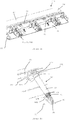
- FIG. 1a shows a partially cut-away perspective view of part of an aircraft wing 10 according to a first embodiment of the invention.
- the aircraft wing 10 comprises an aircraft wing body 20 and a number of Krueger flaps 30 forming the lower leading edge of the aircraft wing 10.
- the aircraft wing body comprises a front spar 21, an upper cover 23 and a lower cover (24, not shown in Figure 1a ).
- the aircraft wing body 20 also comprises a number of ribs 22, arranged in adjacent pairs, extending forwards from the front spar 21.
- the aircraft wing 10 comprises a number of linkage systems 80, 90, 100 which will be described in more detail in relation to Figure 4 .
- Each linkage system 80, 90, 100 is located between a pair of adjacent ribs 22 and is used to control the movement path of one of the Krueger flaps 30.
- the aircraft wing 10 also comprises a deployment mechanism 60 and actuation system for each Krueger flap 30. One of these is shown enlarged in Figure 1b .
- the deployment mechanism 60 comprises a telescopic rod 61, which is attached at a first end to a ball screw actuator 70 and at a second end to the Krueger flap 30.
- the telescopic rod 61 comprises three sections; an outermost rod section 62, an intermediate rod section 63 and an innermost rod section 64.
- the outermost rod section 62 is attached to the ball screw actuator 70 at the first end of the telescopic rod 61.
- the outermost rod section 62 has an internally threaded portion (67a, not shown in Figure 1b ).
- the intermediate rod section 63 has a smaller diameter than the outermost rod section with an externally threaded portion 67b corresponding to the internally threaded portion 67a of the outermost rod section 62.
- the intermediate rod section 63 can be screwed in and out of the outermost rod section 62.
- the intermediate rod section 63 also has an internally threaded portion (68a, not shown in Figure 1b ).
- the innermost rod section 64 has a smaller diameter than the intermediate rod section with an externally threaded portion 68b corresponding to the internally threaded portion 68a of the intermediate rod section 63.
- the innermost rod section 64 can be screwed in and out of the intermediate rod section 63.
- the innermost rod section 64 comprises a flat bulbous portion 65 at the second end of the telescopic rod 61.
- This bulbous portion 65 has a spherical bearing installed in a hole through it and is attached to a bracket 40 by a pin extending through the bulbous portion 65 and also through bushes installed in holes 43, 44 in two lugs 41, 42 of the bracket 40.
- Each lug 41, 42 is located either side of the bulbous portion 65 so that the bulbous portion 65 is pivotally mounted between the lugs 41, 42 of the bracket 40.
- the bracket 40 also comprises a flat base portion 46 that is attached to an interior surface 33 of the Krueger flap 30.
- the ball screw actuator 70 (which will be described in more detail in relation to Figure 3 ) is attached at its other end to a universal joint 73.
- the universal joint 73 is also attached to a gear housing 74.
- the gear housing is attached to the front spar 21 of the aircraft wing 10 by a bracket 75.
- Underneath the gear housing 74 is a worm gear 76 mounted on a rotational shaft 77.
- the rotational shaft 77 is mounted on the front spar 21 by brackets 78 and extends along in front of the front spar 21 and provides a rotational movement to the worm gear 76 for each deployment mechanism 60 in the wing 10.
- Figure 2a shows a partially cut-away perspective view of part of an aircraft wing 510 according to a second embodiment of the invention.
- This second embodiment is similar to the first embodiment with the exception that the actuation system is different; while the first embodiment has a mechanical shaft 77 actuation system for actuating the ball screw actuator 70, the second embodiment uses an electrical motor 573 for doing so.
- like numerals will be used for like elements between the embodiments. Elements unique to or different in the second embodiment will be prefixed with "5".
- the ball screw actuator 70 is attached to a plate 575.
- the plate 575 is attached to a bracket 576, secured to the front spar 21.
- an electrical motor 573 is attached to the plate 575 and is electrically connected to the ball screw actuator 70.
- An electrical harness 574 connects the electric motor 573 to an electricity supply in the aircraft.
- a potentiometer (not shown) attached to the electrical motor 573 to monitor the function of the electrical motor 573 and/or ball screw actuator 70.
- the deployment mechanism 60 shown in Figure 2b is almost identical to that in Figure 1a .
- the deployment mechanism 60 as shown in Figure 2b has a longer outermost rod section 62 and so, for the same position of the Krueger flap 30, the intermediate 63 and innermost 64 rod sections have less length protruding from the outermost rod section 62.
- the outermost rod section 62 can be longer than in the first embodiment due to the electrical actuation system of the second embodiment being smaller than the mechanical actuation system of the first embodiment.
- FIG. 3 shows a partially cut-away side view of one ball screw actuator 70 in either the first or second embodiments.
- the ball screw actuator 70 comprises ball bearings 71 which fit into two sets of channels 72 formed between two internally threaded portions 67a of the outermost rod section 62 and the externally threaded portion 67b of the intermediate rod section 63.
- the ball bearings 71 fill up the two sets of channels and cause the intermediate rod section 63 to move in relation to the outermost rod section 62.
- Figure 4 shows a perspective view of the linkage system 80, 90, 100 in either the first or second embodiments.
- the linkage system comprises three components; an A-link 80, a support bracket 90 and an I-link 100.
- the A-link 80 comprises an A-frame 81.
- the A-frame 81 is provided with two foot portions 82, 83 extending behind the "A" shape from the bottom of the two legs of the "A" shape.
- Each foot portion 82, 83 is provided with a hole 84, 85.
- a pin 88 is located through bushes in the two holes 84, 85 so that the pin 88 is parallel to but behind the bottom of the "A" shape.
- the pin 88 is fixed between a pair of adjacent ribs 22a, 22b at the leading edge of the aircraft wing 510.
- the A-frame 81 can pivot around the pin 88 and so can pivot with respect to the aircraft wing body 20.
- Adjacent to the top apex of the A-frame 81 is another bush installed in a hole 86 that is parallel to the bottom of the "A" shape. This hole 86 accommodates another pin 87. This pin 87 is attached to a supporting structure 50 of the Krueger flap 30, as will be described later.
- the A-link 80 is designed to react lateral loads from the Krueger flap 30.
- the supporting bracket 90 comprises two side flanges 91, 92, each one being riveted 93 to an inner facing side of each of the adjacent pair of ribs 22a, 22b.
- the supporting bracket 90 has a top portion 94 with a central gap 95 in the top portion.
- the supporting bracket 90 also has a downwards facing foot portion 96 at the bottom centre of the supporting bracket 90.
- This foot portion 96 has two lugs 97, each with a hole 98 in. These two holes 98 accommodate the pin 88 so that the supporting bracket 90 helps to secure the pin 88 to the ribs 22.
- Adjacent to the holes 98 and slightly above them is another set of holes 99 through the foot portion 96. These holes 99 connect the I-link 100.
- the I-link 100 comprises an I-beam 101 with a tail portion 102 that is slightly angled. At the end of the tail portion 102 is a hole 103.
- the I-link 100 is connected to the supporting bracket 90 by a pin 104 extending through a spherical bearing installed in the hole 103 in the I-link 100 and bushed installed in holes 99 in the supporting bracket 90.
- the I-beam can pivot about pin 104.
- At the non-tail end of the I-beam 101 is another hole 105 with a bearing installed in it.
- the hole 105 has an axis that is parallel to the pin 104. This hole 105 accommodates another pin 106.
- This pin 106 is attached to a supporting structure 50 of the Krueger flap 30, as will be described later.
- the I-link 100 is designed to react shear loads from the Krueger flap 30.
- Figure 5a shows a side view of part of the aircraft wing of Figures 2a and 2b , showing one Krueger flap 30 in a fully stowed position.
- Figure 5b shows the Krueger flap 30 in a partially deployed position
- Figure 5c shows the Krueger flap 30 in a fully deployed position.
- the Krueger flap In the partially deployed position of Figure 5b , the Krueger flap is at approximately 90 degrees to the wing.
- the Krueger flap can act as a brake.
- the Krueger flap 30 and its supporting structure 50 will now be described in relation to these figures. Importantly, the Krueger flap 30 and its supporting structure 50 are the same as in the first embodiment and so the following description applies to the first embodiment too.
- the Krueger flap 30 is in the shape of a cambered aerofoil with a bluff rounded end 31 and a tapered narrow end 32. As can be seen in Figure 5a , when stowed, the flap 30 is stowed with its bluff end 31 towards the rear of the wing 510 and the tapered end 32 at the leading edge of the wing 510. An interior surface 33 of the flap 30 sits adjacent to the underside of the main wing body 20 with an exterior surface 34 forming the underside leading edge profile of the wing 510.
- a supporting structure 50 for the Krueger flap 30 is in the form of a right-angled triangle beam.
- a short side 51 of the beam is placed inside the flap 30 so that it is abutting the inside of the exterior surface 34 of the flap 30.
- a longer side 52 of the beam that is at right angles to the short side 51 extends outwards from the flap 30 to the apex of the beam.
- a sloping side 53 of the beam extends from the apex in the direction of the tapered end 32 of the Krueger flap 30.
- a hole 54 for accommodating pin 106 of the I-link 100 to allow the I-link to pivot with respect to the supporting structure 50 and Krueger flap 30.
- Approximately one third of the distance along the sloping side 53 from the apex is another hole 55 for accommodating pin 87 of the A-link 80 to allow the A-link to pivot with respect to the supporting structure 50 and Krueger flap 30.
- the Krueger flap 30 is moved in relation to the aircraft wing body 20 from a stowed position (in Figure 5a ), for example during cruise, to a fully deployed position (in Figure 5c ), for example for take-off and landing operations.
- a stowed position In the stowed position, the Krueger flap 30 profile is blended with the leading edge lower profile of the aircraft wing 510 and so laminar flow along the wing is not disturbed.
- the Krueger flap 30 provides an auxiliary wing surface in front of the leading edge of the aircraft wing body 20. This increases the lift co-efficient of the wing 510.
- the Krueger flap is at approximately 120 degrees to the wing.
- the Krueger flap can act as a shield for protecting the leading edge of the wing from debris, for example during take-off.
- the Krueger flap 30 During take-off and landing, the Krueger flap 30 is in its fully deployed position ( Figure 5c ). Once the aircraft has taken off and its speed has increased so that the auxiliary wing surface is no longer required, the Krueger flap 30 can be retracted into its stowed position. This is done by actuating either the electric motor 573 (in the second embodiment) or the rotational shaft 77 (in the first embodiment).
- the rotational shaft 77 causes the worm gear 76 to rotate and this causes the gear in the gear housing 74 to also rotate. This actuates the ball screw actuator 70.
- the electric motor 573 actuates the ball screw actuator 70 directly.
- the intermediate rod section 63 is retracted into the outermost rod section 62 and also the innermost rod section 64 is retracted into the intermediate rod section 63.
- the Krueger flap 30 can be re-extended into its deployed position. This is done by actuating either the electric motor 573 (in the second embodiment) or the rotational shaft 77 (in the first embodiment).
- the rotational shaft 77 is rotated in the opposite direction to during retraction, which causes the worm gear 76 to rotate in the opposite direction and this causes the gear in the gear housing 74 to also rotate in the opposite direction to before. This actuates the ball screw actuator 70 to deploy the flap 30.
- the electric motor 573 actuates the ball screw actuator 70 to deploy the flap 30 directly.
- the intermediate rod section 63 is extended out of the outermost rod section 62 and also the innermost rod section 64 is extended out of the intermediate rod section 63.
- a magnetic sensor at each end of the rotational shaft 77 may be used instead of having an optical sensor at each end of the rotational shaft 77 for monitoring the function and position of the rotational shaft 77.
- the Krueger flap 30 may also be deployed (or at least partially deployed) during cruise flight of the aircraft to act as an air brake.
Landscapes
- Engineering & Computer Science (AREA)
- Aviation & Aerospace Engineering (AREA)
- Transmission Devices (AREA)
- Automation & Control Theory (AREA)
- Mechanical Engineering (AREA)
- Braking Arrangements (AREA)
- Mechanical Control Devices (AREA)
Claims (12)
- Luftfahrzeugflügel (10) umfassend einen Flügelkörper (20), eine Hilfsflügel-Oberflächeneinrichtung (30) und einen Einsatzmechanismus (60) zum Einsetzen der Hilfsflügel-Oberflächeneinrichtung, wobei der Einsatzmechanismus aufweist:- einen ersten Verbindungsabschnitt (75) zur Verbindung des Einsatzmechanismus mit dem Luftfahrzug-Flügelkörper,- einen zweiten Verbindungsabschnitt (65) zur Verbindung des Einsatzmechanismus mit der Hilfsflügel-Oberflächeneinrichtung, und- einen Teleskopstab (61) welcher den ersten und den zweiten Verbindungsabschnitt miteinander verbindet,wobei der Teleskopstab einen inneren Stab (64) aufweist, welcher aus einem äußeren Stab (62) zur Erhöhung der Länge des Teleskopstabes derart ausfahrbar ist, dass der Abstand des Luftfahrzug-Flügelkörpers zur Hilfsflügel-Oberflächeneinrichtung erhöht werden kann, dadurch gekennzeichnet, dass der Luftfahrzeugflügel zusätzlich eine Anzahl an Verbindungen zwischen der Hilfsflügel-Oberflächeneinrichtung und dem Luftfahrzug-Flügelkörper aufweist, wobei die Verbindungen den Laufweg der Hilfsflügel-Oberflächeneinrichtung in Bezug auf den Luftfahrzug-Flügelkörper definieren, wenn die Länge des Teleskopstabes erhöht wird, und
wobei eine erste Verbindung (80) zur Ableitung von Seitenlasten von der Hilfsflügel-Oberflächeneinrichtung und eine zweite Verbindung (100) zur Ableitung von Scherlasten vorgesehen sind. - Luftfahrzeugflügel nach Anspruch 1, wobei der Teleskopstab einen innersten Stab, einen äußersten Stab und eine Anzahl an Zwischenstäben (63) aufweist, wobei jeder innere Stab in jedem Paar benachbarter Stäbe aus dem Inneren des äußeren Stabs des Paars benachbarter Stäbe ausfahrbar ausgebildet ist.
- Luftfahrzeugflügel nach einem der Ansprüche 1 oder 2, wobei die Hilfsflügel-Oberflächeneinrichtung an der Vorderkante des Luftfahrzeugflügels angeordnet ist.
- Luftfahrzeugflügel nach Anspruch 3, wobei die Hilfsflügel-Oberflächeneinrichtung als Krügerklapp (30) ausgebildet ist.
- Luftfahrzeugflügel nach einem der vorhergehenden Ansprüche, wobei eine Halterung des ersten Verbindungsabschnitts an einem Holm (21), vorzugsweise einem Vorderholm, des Luftfahrzeugflügels befestigt ist.
- Luftfahrzeugflügel nach einem der vorhergehenden Ansprüche, wobei die Verbindungen mit einer oder mehrerer der Rippen des Luftfahrzug-Flügelkörpers verbunden sind.
- Luftfahrzeugflügel nach einem der vorhergehenden Ansprüche, wobei der Luftfahrzeugflügel eine Stützstruktur (90) aufweist, welche an der Hilfsflügel-Oberflächeneinrichtung befestigt ist, und wobei jede der beiden Verbindungen (80, 100) drehbar mit der Stützstruktur verbunden ist und wobei die beiden Verbindungen an verschiedenen Stellen mit der Stützstruktur verbunden sind derart, dass ihre Rotationsachsen bezogen auf die Hilfsflügel-Oberflächeneinrichtung voneinander beabstandet sind.
- Luftfahrzeugflügel nach einem der vorhergehenden Ansprüche, wobei der Luftfahrzug-Flügelkörper einen Drehzapfen (87) aufweist, welcher an einer oder mehreren Rippen des Luftfahrzug-Flügelkörpers befestigt ist und wobei eine der Verbindungen, vorzugsweise die erste Verbindung, um den Drehzapfen drehbar verbunden ist.
- Luftfahrzeugflügel nach einem der vorhergehenden Ansprüche, wobei die beiden Verbindungen (80, 100) drehbar an unterschiedlichen Positionen derart mit dem Luftfahrzug-Flügelkörper verbunden sind, dass ihre Rotationsachsen bezüglich des Luftfahrzug-Flügelkörpers voneinander beabstandet sind.
- Luftfahrzeug umfassend den Luftfahrzeugflügel nach einem der vorhergehenden Ansprüche.
- Verfahren zum Betreiben eines Luftfahrzeugs nach Anspruch 10, wobei das Verfahren die Schritte folgenden Schritte aufweist:- Betätigen eines Teleskopstabes (61) derart, dass ein innerer Stab (64) des Teleskopstabes aus dem Inneren eines äußeren Stabes (62) des Teleskopstabes hervortritt, um die Länge des Teleskopstabes zu erhöhen,- hierdurch Erhöhen des Abstands zwischen einem ersten Verbindungsabschnitt (75) an einem ersten Ende des Teleskopstabes und einem zweiten Verbindungsabschnitt (65) an einem zweiten Ende des Teleskopstabes, wobei der erste Verbindungsabschnitt mit der Hilfsflügeloberflächeneinrichtung (30) verbunden ist, und der zweite Verbindungsabschnitt mit dem Luftfahrzug-Flügelkörper verbunden ist, und- hierdurch Ausfahren der Hilfsflügel-Oberflächeneinrichtung vom Luftfahrzug-Flügelkörper,dadurch gekennzeichnet, dass
der Luftfahrzeugflügel zusätzlich einen Anzahl an Verbindungen (80, 90, 100) zwischen der Hilfsflügel-Oberflächeneinrichtung und dem Luftfahrzug-Flügelkörper aufweist, wobei die Verbindungen den Laufweg der Hilfsflügel-Oberflächeneinrichtung bezüglich des Luftfahrzug-Flügelkörpersdefinieren, wenn die Länge des Teleskopstabes erhöht wird, und wobei eine erste Verbindung (80) zur Ableitung von Seitenlast von der Hilfsflügel-Oberflächeneinrichtung und eine zweite Verbindung (100) zur Ableitung von Scherlast vorgesehen sind. - Verfahren zum Betreiben eines Luftfahrzeugflügels, wobei das Verfahren die folgenden Schritte aufweist:- Betätigen eines Teleskopstabes (61) derart, dass ein innerer Stab (64) des Teleskopstabes in das Innere eines äußeren Stabes (62) des Teleskopstabes eintritt, um die Länge des Teleskopstabes zu verringern,- hierdurch Verringern des Abstands zwischen einem ersten Verbindungsabschnitt (75) an einem ersten Ende des Teleskopstabes und einem zweiten Verbindungsabschnitt (65) an einem zweiten Ende des Teleskopstabes, wobei der erste Verbindungsabschnitt mit der Hilfsflügeloberflächeneinrichtung (30) verbunden ist, und der zweite Verbindungsabschnitt mit dem Luftfahrzug-Flügelkörper verbunden ist, und- hierdurch Einfahren der Hilfsflügel-Oberflächeneinrichtung zum Luftfahrzug-Flügelkörper,dadurch gekennzeichnet, dass
der Luftfahrzeugflügel zusätzlich einen Anzahl an Verbindungen (80, 90, 100) zwischen der Hilfsflügel-Oberflächeneinrichtung und dem Luftfahrzug-Flügelkörper aufweist, wobei die Verbindungen den Laufweg der Hilfsflügel-Oberflächeneinrichtung bezüglich des Luftfahrzug-Flügelkörpers definieren, wenn die Länge des Teleskopstabes erhöht wird, und wobei eine erste Verbindung (80) zur Ableitung von Seitenlast von der Hilfsflügel-Oberflächeneinrichtung und eine zweite Verbindung (100) zur Ableitung von Scherlast vorgesehen sind.
Applications Claiming Priority (1)
| Application Number | Priority Date | Filing Date | Title |
|---|---|---|---|
| GBGB1220885.6A GB201220885D0 (en) | 2012-11-20 | 2012-11-20 | An improved deployment mechanism |
Publications (2)
| Publication Number | Publication Date |
|---|---|
| EP2762404A1 EP2762404A1 (de) | 2014-08-06 |
| EP2762404B1 true EP2762404B1 (de) | 2017-03-15 |
Family
ID=47521456
Family Applications (1)
| Application Number | Title | Priority Date | Filing Date |
|---|---|---|---|
| EP13193195.8A Not-in-force EP2762404B1 (de) | 2012-11-20 | 2013-11-15 | Verbesserter Einsetzmechanismus |
Country Status (4)
| Country | Link |
|---|---|
| US (1) | US9174724B2 (de) |
| EP (1) | EP2762404B1 (de) |
| CN (1) | CN103832579B (de) |
| GB (1) | GB201220885D0 (de) |
Families Citing this family (15)
| Publication number | Priority date | Publication date | Assignee | Title |
|---|---|---|---|---|
| FR3016607B1 (fr) * | 2014-01-20 | 2016-01-22 | Sagem Defense Securite | Actionneur de commande d'un plan horizontal de stabilisation d'un aeronef |
| DE102015104484B4 (de) * | 2015-03-25 | 2016-12-22 | A. Mannesmann Maschinenfabrik Gmbh | Vierstufiger Teleskopaktor mit Gewindetrieb |
| CN109070995A (zh) * | 2016-02-01 | 2018-12-21 | 都铎克洛斯费尔特有限责任公司 | 一种用于摆翼的折叠梁 |
| EP3339164A1 (de) * | 2016-12-22 | 2018-06-27 | Airbus Operations GmbH | Flügel für ein flugzeug |
| EP3339163A1 (de) * | 2016-12-22 | 2018-06-27 | Airbus Operations GmbH | Flügel für ein flugzeug |
| US10501201B2 (en) * | 2017-03-27 | 2019-12-10 | Hamilton Sundstrand Corporation | Aerodynamic control surface movement monitoring system for aircraft |
| US10974816B2 (en) * | 2017-09-28 | 2021-04-13 | The Boeing Company | High-fowler flap actuation apparatus and related methods |
| EP3489547B1 (de) * | 2017-11-27 | 2022-05-04 | Rohr, Inc. | Schubumkehrer mit bewegungssteuerungsvorrichtung |
| EP4140877B1 (de) * | 2019-01-18 | 2025-07-02 | Asco Industries NV | Vorflügel für einen flugzeugflügel, verfahren zur herstellung solch eines vorflügels |
| EP3750799B1 (de) * | 2019-06-14 | 2022-09-07 | Goodrich Actuation Systems SAS | Obere stellgliedbefestigung |
| CN114174167B (zh) * | 2019-08-30 | 2025-07-18 | 空中客车德国运营有限责任公司 | 前缘组件、机翼和飞行器 |
| CN111003157A (zh) * | 2019-12-24 | 2020-04-14 | 中国航空工业集团公司西安飞机设计研究所 | 一种桁架式襟翼摇臂结构 |
| US12296954B2 (en) * | 2021-05-26 | 2025-05-13 | The Boeing Company | Thin wing drive mechanism |
| EP4303122A1 (de) | 2022-07-07 | 2024-01-10 | Airbus Operations GmbH | Flügel für ein flugzeug |
| BE1032729B1 (fr) * | 2024-06-28 | 2026-02-03 | Sonaca Sa | Volet mobile de bord d'attaque d'une aile d'aéronef, présentant une forme nominale courbe afin de s'adapter à la déformée de l'aile en vol |
Family Cites Families (10)
| Publication number | Priority date | Publication date | Assignee | Title |
|---|---|---|---|---|
| DE1338506U (de) * | ||||
| GB991405A (en) * | 1960-05-19 | 1965-05-05 | Dehavilland Aircraft | Improvements relating to aircraft |
| US3404580A (en) * | 1967-04-18 | 1968-10-08 | Sargent Industries | Ball screw actuator |
| US5313852A (en) * | 1992-11-06 | 1994-05-24 | Grumman Aerospace Corporation | Differential linear actuator |
| EP1338506A1 (de) * | 2002-02-15 | 2003-08-27 | Fairchild Dornier GmbH | Flugzeugflügel mit Spalt- und Krüger-Klappen |
| EP1731421B1 (de) | 2005-06-09 | 2008-08-13 | Claverham Limited | Elektro-mechanischer Lineartrieb |
| FR2917788B1 (fr) * | 2007-06-19 | 2009-07-24 | Aircelle Sa | Actionneur double action a effet programme |
| US7766282B2 (en) | 2007-12-11 | 2010-08-03 | The Boeing Company | Trailing edge device catchers and associated systems and methods |
| FR2968375B1 (fr) | 2010-12-06 | 2013-08-02 | Messier Bugatti | Actionneur telescopique electromecanique. |
| FR2976040B1 (fr) | 2011-06-06 | 2015-05-22 | Messier Bugatti Dowty | Actionneur telescopique. |
-
2012
- 2012-11-20 GB GBGB1220885.6A patent/GB201220885D0/en not_active Ceased
-
2013
- 2013-11-15 EP EP13193195.8A patent/EP2762404B1/de not_active Not-in-force
- 2013-11-18 US US14/082,327 patent/US9174724B2/en active Active
- 2013-11-20 CN CN201310589210.4A patent/CN103832579B/zh not_active Expired - Fee Related
Also Published As
| Publication number | Publication date |
|---|---|
| GB201220885D0 (en) | 2013-01-02 |
| US9174724B2 (en) | 2015-11-03 |
| CN103832579A (zh) | 2014-06-04 |
| CN103832579B (zh) | 2018-08-17 |
| EP2762404A1 (de) | 2014-08-06 |
| US20140138481A1 (en) | 2014-05-22 |
Similar Documents
| Publication | Publication Date | Title |
|---|---|---|
| EP2762404B1 (de) | Verbesserter Einsetzmechanismus | |
| US8118254B2 (en) | Flap actuator | |
| JP4319003B2 (ja) | 航空機、装置および航空機を製造するための方法 | |
| US10899431B2 (en) | System for driving and guiding of a multifunctional trailing edge control surface on an aircraft | |
| US6684623B2 (en) | Gearless electric thrust reverser actuators and actuation system incorporating same | |
| US7309043B2 (en) | Actuation device positioning systems and associated methods, including aircraft spoiler droop systems | |
| US8393568B2 (en) | Enhanced lubrication skewed roller clutch assembly and actuator including same | |
| CA2857892C (en) | Adaptive trailing edge actuator system and method | |
| EP2433863B1 (de) | Vorflügelaufhängung | |
| US6467733B1 (en) | Aerodynamic control surface system | |
| EP3461738A1 (de) | Fowler-klappenbetätigungsvorrichtung und zugehörige verfahren | |
| JP4646543B2 (ja) | 航空機の可動翼のための、回転可能な部材を作動させる装置 |
Legal Events
| Date | Code | Title | Description |
|---|---|---|---|
| PUAI | Public reference made under article 153(3) epc to a published international application that has entered the european phase |
Free format text: ORIGINAL CODE: 0009012 |
|
| 17P | Request for examination filed |
Effective date: 20131115 |
|
| AK | Designated contracting states |
Kind code of ref document: A1 Designated state(s): AL AT BE BG CH CY CZ DE DK EE ES FI FR GB GR HR HU IE IS IT LI LT LU LV MC MK MT NL NO PL PT RO RS SE SI SK SM TR |
|
| AX | Request for extension of the european patent |
Extension state: BA ME |
|
| R17P | Request for examination filed (corrected) |
Effective date: 20150513 |
|
| RBV | Designated contracting states (corrected) |
Designated state(s): AL AT BE BG CH CY CZ DE DK EE ES FI FR GB GR HR HU IE IS IT LI LT LU LV MC MK MT NL NO PL PT RO RS SE SI SK SM TR |
|
| GRAP | Despatch of communication of intention to grant a patent |
Free format text: ORIGINAL CODE: EPIDOSNIGR1 |
|
| INTG | Intention to grant announced |
Effective date: 20160927 |
|
| STAA | Information on the status of an ep patent application or granted ep patent |
Free format text: STATUS: GRANT OF PATENT IS INTENDED |
|
| GRAS | Grant fee paid |
Free format text: ORIGINAL CODE: EPIDOSNIGR3 |
|
| GRAA | (expected) grant |
Free format text: ORIGINAL CODE: 0009210 |
|
| STAA | Information on the status of an ep patent application or granted ep patent |
Free format text: STATUS: THE PATENT HAS BEEN GRANTED |
|
| AK | Designated contracting states |
Kind code of ref document: B1 Designated state(s): AL AT BE BG CH CY CZ DE DK EE ES FI FR GB GR HR HU IE IS IT LI LT LU LV MC MK MT NL NO PL PT RO RS SE SI SK SM TR |
|
| REG | Reference to a national code |
Ref country code: CH Ref legal event code: EP Ref country code: GB Ref legal event code: FG4D |
|
| REG | Reference to a national code |
Ref country code: IE Ref legal event code: FG4D |
|
| REG | Reference to a national code |
Ref country code: AT Ref legal event code: REF Ref document number: 875239 Country of ref document: AT Kind code of ref document: T Effective date: 20170415 |
|
| REG | Reference to a national code |
Ref country code: DE Ref legal event code: R096 Ref document number: 602013018519 Country of ref document: DE |
|
| REG | Reference to a national code |
Ref country code: NL Ref legal event code: MP Effective date: 20170315 |
|
| REG | Reference to a national code |
Ref country code: LT Ref legal event code: MG4D |
|
| PG25 | Lapsed in a contracting state [announced via postgrant information from national office to epo] |
Ref country code: NO Free format text: LAPSE BECAUSE OF FAILURE TO SUBMIT A TRANSLATION OF THE DESCRIPTION OR TO PAY THE FEE WITHIN THE PRESCRIBED TIME-LIMIT Effective date: 20170615 Ref country code: FI Free format text: LAPSE BECAUSE OF FAILURE TO SUBMIT A TRANSLATION OF THE DESCRIPTION OR TO PAY THE FEE WITHIN THE PRESCRIBED TIME-LIMIT Effective date: 20170315 Ref country code: GR Free format text: LAPSE BECAUSE OF FAILURE TO SUBMIT A TRANSLATION OF THE DESCRIPTION OR TO PAY THE FEE WITHIN THE PRESCRIBED TIME-LIMIT Effective date: 20170616 Ref country code: LT Free format text: LAPSE BECAUSE OF FAILURE TO SUBMIT A TRANSLATION OF THE DESCRIPTION OR TO PAY THE FEE WITHIN THE PRESCRIBED TIME-LIMIT Effective date: 20170315 Ref country code: HR Free format text: LAPSE BECAUSE OF FAILURE TO SUBMIT A TRANSLATION OF THE DESCRIPTION OR TO PAY THE FEE WITHIN THE PRESCRIBED TIME-LIMIT Effective date: 20170315 |
|
| REG | Reference to a national code |
Ref country code: AT Ref legal event code: MK05 Ref document number: 875239 Country of ref document: AT Kind code of ref document: T Effective date: 20170315 |
|
| PG25 | Lapsed in a contracting state [announced via postgrant information from national office to epo] |
Ref country code: BG Free format text: LAPSE BECAUSE OF FAILURE TO SUBMIT A TRANSLATION OF THE DESCRIPTION OR TO PAY THE FEE WITHIN THE PRESCRIBED TIME-LIMIT Effective date: 20170615 Ref country code: LV Free format text: LAPSE BECAUSE OF FAILURE TO SUBMIT A TRANSLATION OF THE DESCRIPTION OR TO PAY THE FEE WITHIN THE PRESCRIBED TIME-LIMIT Effective date: 20170315 Ref country code: RS Free format text: LAPSE BECAUSE OF FAILURE TO SUBMIT A TRANSLATION OF THE DESCRIPTION OR TO PAY THE FEE WITHIN THE PRESCRIBED TIME-LIMIT Effective date: 20170315 Ref country code: SE Free format text: LAPSE BECAUSE OF FAILURE TO SUBMIT A TRANSLATION OF THE DESCRIPTION OR TO PAY THE FEE WITHIN THE PRESCRIBED TIME-LIMIT Effective date: 20170315 |
|
| PG25 | Lapsed in a contracting state [announced via postgrant information from national office to epo] |
Ref country code: NL Free format text: LAPSE BECAUSE OF FAILURE TO SUBMIT A TRANSLATION OF THE DESCRIPTION OR TO PAY THE FEE WITHIN THE PRESCRIBED TIME-LIMIT Effective date: 20170315 |
|
| PG25 | Lapsed in a contracting state [announced via postgrant information from national office to epo] |
Ref country code: SK Free format text: LAPSE BECAUSE OF FAILURE TO SUBMIT A TRANSLATION OF THE DESCRIPTION OR TO PAY THE FEE WITHIN THE PRESCRIBED TIME-LIMIT Effective date: 20170315 Ref country code: AT Free format text: LAPSE BECAUSE OF FAILURE TO SUBMIT A TRANSLATION OF THE DESCRIPTION OR TO PAY THE FEE WITHIN THE PRESCRIBED TIME-LIMIT Effective date: 20170315 Ref country code: EE Free format text: LAPSE BECAUSE OF FAILURE TO SUBMIT A TRANSLATION OF THE DESCRIPTION OR TO PAY THE FEE WITHIN THE PRESCRIBED TIME-LIMIT Effective date: 20170315 Ref country code: RO Free format text: LAPSE BECAUSE OF FAILURE TO SUBMIT A TRANSLATION OF THE DESCRIPTION OR TO PAY THE FEE WITHIN THE PRESCRIBED TIME-LIMIT Effective date: 20170315 Ref country code: ES Free format text: LAPSE BECAUSE OF FAILURE TO SUBMIT A TRANSLATION OF THE DESCRIPTION OR TO PAY THE FEE WITHIN THE PRESCRIBED TIME-LIMIT Effective date: 20170315 Ref country code: CZ Free format text: LAPSE BECAUSE OF FAILURE TO SUBMIT A TRANSLATION OF THE DESCRIPTION OR TO PAY THE FEE WITHIN THE PRESCRIBED TIME-LIMIT Effective date: 20170315 Ref country code: IT Free format text: LAPSE BECAUSE OF FAILURE TO SUBMIT A TRANSLATION OF THE DESCRIPTION OR TO PAY THE FEE WITHIN THE PRESCRIBED TIME-LIMIT Effective date: 20170315 |
|
| REG | Reference to a national code |
Ref country code: FR Ref legal event code: PLFP Year of fee payment: 5 |
|
| PG25 | Lapsed in a contracting state [announced via postgrant information from national office to epo] |
Ref country code: IS Free format text: LAPSE BECAUSE OF FAILURE TO SUBMIT A TRANSLATION OF THE DESCRIPTION OR TO PAY THE FEE WITHIN THE PRESCRIBED TIME-LIMIT Effective date: 20170715 Ref country code: SM Free format text: LAPSE BECAUSE OF FAILURE TO SUBMIT A TRANSLATION OF THE DESCRIPTION OR TO PAY THE FEE WITHIN THE PRESCRIBED TIME-LIMIT Effective date: 20170315 Ref country code: PL Free format text: LAPSE BECAUSE OF FAILURE TO SUBMIT A TRANSLATION OF THE DESCRIPTION OR TO PAY THE FEE WITHIN THE PRESCRIBED TIME-LIMIT Effective date: 20170315 Ref country code: PT Free format text: LAPSE BECAUSE OF FAILURE TO SUBMIT A TRANSLATION OF THE DESCRIPTION OR TO PAY THE FEE WITHIN THE PRESCRIBED TIME-LIMIT Effective date: 20170717 |
|
| REG | Reference to a national code |
Ref country code: DE Ref legal event code: R097 Ref document number: 602013018519 Country of ref document: DE |
|
| PLBE | No opposition filed within time limit |
Free format text: ORIGINAL CODE: 0009261 |
|
| STAA | Information on the status of an ep patent application or granted ep patent |
Free format text: STATUS: NO OPPOSITION FILED WITHIN TIME LIMIT |
|
| PG25 | Lapsed in a contracting state [announced via postgrant information from national office to epo] |
Ref country code: DK Free format text: LAPSE BECAUSE OF FAILURE TO SUBMIT A TRANSLATION OF THE DESCRIPTION OR TO PAY THE FEE WITHIN THE PRESCRIBED TIME-LIMIT Effective date: 20170315 |
|
| 26N | No opposition filed |
Effective date: 20171218 |
|
| PG25 | Lapsed in a contracting state [announced via postgrant information from national office to epo] |
Ref country code: SI Free format text: LAPSE BECAUSE OF FAILURE TO SUBMIT A TRANSLATION OF THE DESCRIPTION OR TO PAY THE FEE WITHIN THE PRESCRIBED TIME-LIMIT Effective date: 20170315 |
|
| PG25 | Lapsed in a contracting state [announced via postgrant information from national office to epo] |
Ref country code: MC Free format text: LAPSE BECAUSE OF FAILURE TO SUBMIT A TRANSLATION OF THE DESCRIPTION OR TO PAY THE FEE WITHIN THE PRESCRIBED TIME-LIMIT Effective date: 20170315 |
|
| PG25 | Lapsed in a contracting state [announced via postgrant information from national office to epo] |
Ref country code: LI Free format text: LAPSE BECAUSE OF NON-PAYMENT OF DUE FEES Effective date: 20171130 Ref country code: CH Free format text: LAPSE BECAUSE OF NON-PAYMENT OF DUE FEES Effective date: 20171130 |
|
| PG25 | Lapsed in a contracting state [announced via postgrant information from national office to epo] |
Ref country code: LU Free format text: LAPSE BECAUSE OF NON-PAYMENT OF DUE FEES Effective date: 20171115 |
|
| REG | Reference to a national code |
Ref country code: BE Ref legal event code: MM Effective date: 20171130 |
|
| REG | Reference to a national code |
Ref country code: IE Ref legal event code: MM4A |
|
| PG25 | Lapsed in a contracting state [announced via postgrant information from national office to epo] |
Ref country code: MT Free format text: LAPSE BECAUSE OF NON-PAYMENT OF DUE FEES Effective date: 20171115 |
|
| PG25 | Lapsed in a contracting state [announced via postgrant information from national office to epo] |
Ref country code: IE Free format text: LAPSE BECAUSE OF NON-PAYMENT OF DUE FEES Effective date: 20171115 |
|
| PG25 | Lapsed in a contracting state [announced via postgrant information from national office to epo] |
Ref country code: BE Free format text: LAPSE BECAUSE OF NON-PAYMENT OF DUE FEES Effective date: 20171130 |
|
| PG25 | Lapsed in a contracting state [announced via postgrant information from national office to epo] |
Ref country code: HU Free format text: LAPSE BECAUSE OF FAILURE TO SUBMIT A TRANSLATION OF THE DESCRIPTION OR TO PAY THE FEE WITHIN THE PRESCRIBED TIME-LIMIT; INVALID AB INITIO Effective date: 20131115 |
|
| PG25 | Lapsed in a contracting state [announced via postgrant information from national office to epo] |
Ref country code: CY Free format text: LAPSE BECAUSE OF NON-PAYMENT OF DUE FEES Effective date: 20170315 |
|
| PG25 | Lapsed in a contracting state [announced via postgrant information from national office to epo] |
Ref country code: MK Free format text: LAPSE BECAUSE OF FAILURE TO SUBMIT A TRANSLATION OF THE DESCRIPTION OR TO PAY THE FEE WITHIN THE PRESCRIBED TIME-LIMIT Effective date: 20170315 |
|
| PG25 | Lapsed in a contracting state [announced via postgrant information from national office to epo] |
Ref country code: TR Free format text: LAPSE BECAUSE OF FAILURE TO SUBMIT A TRANSLATION OF THE DESCRIPTION OR TO PAY THE FEE WITHIN THE PRESCRIBED TIME-LIMIT Effective date: 20170315 |
|
| PG25 | Lapsed in a contracting state [announced via postgrant information from national office to epo] |
Ref country code: AL Free format text: LAPSE BECAUSE OF FAILURE TO SUBMIT A TRANSLATION OF THE DESCRIPTION OR TO PAY THE FEE WITHIN THE PRESCRIBED TIME-LIMIT Effective date: 20170315 |
|
| PGFP | Annual fee paid to national office [announced via postgrant information from national office to epo] |
Ref country code: GB Payment date: 20211119 Year of fee payment: 9 Ref country code: DE Payment date: 20211118 Year of fee payment: 9 Ref country code: FR Payment date: 20211122 Year of fee payment: 9 |
|
| REG | Reference to a national code |
Ref country code: DE Ref legal event code: R119 Ref document number: 602013018519 Country of ref document: DE |
|
| GBPC | Gb: european patent ceased through non-payment of renewal fee |
Effective date: 20221115 |
|
| PG25 | Lapsed in a contracting state [announced via postgrant information from national office to epo] |
Ref country code: GB Free format text: LAPSE BECAUSE OF NON-PAYMENT OF DUE FEES Effective date: 20221115 Ref country code: DE Free format text: LAPSE BECAUSE OF NON-PAYMENT OF DUE FEES Effective date: 20230601 |
|
| PG25 | Lapsed in a contracting state [announced via postgrant information from national office to epo] |
Ref country code: FR Free format text: LAPSE BECAUSE OF NON-PAYMENT OF DUE FEES Effective date: 20221130 |