EP2762432A1 - Procédé de surveillance destiné à éviter la collision d'une poinçonneuse avec un balai de freinage - Google Patents
Procédé de surveillance destiné à éviter la collision d'une poinçonneuse avec un balai de freinage Download PDFInfo
- Publication number
- EP2762432A1 EP2762432A1 EP20130195409 EP13195409A EP2762432A1 EP 2762432 A1 EP2762432 A1 EP 2762432A1 EP 20130195409 EP20130195409 EP 20130195409 EP 13195409 A EP13195409 A EP 13195409A EP 2762432 A1 EP2762432 A1 EP 2762432A1
- Authority
- EP
- European Patent Office
- Prior art keywords
- brake
- clamping frame
- brush
- brake brush
- machine
- Prior art date
- Legal status (The legal status is an assumption and is not a legal conclusion. Google has not performed a legal analysis and makes no representation as to the accuracy of the status listed.)
- Granted
Links
Images




Classifications
-
- B—PERFORMING OPERATIONS; TRANSPORTING
- B26—HAND CUTTING TOOLS; CUTTING; SEVERING
- B26D—CUTTING; DETAILS COMMON TO MACHINES FOR PERFORATING, PUNCHING, CUTTING-OUT, STAMPING-OUT OR SEVERING
- B26D7/00—Details of apparatus for cutting, cutting-out, stamping-out, punching, perforating, or severing by means other than cutting
- B26D7/22—Safety devices specially adapted for cutting machines
-
- B—PERFORMING OPERATIONS; TRANSPORTING
- B65—CONVEYING; PACKING; STORING; HANDLING THIN OR FILAMENTARY MATERIAL
- B65H—HANDLING THIN OR FILAMENTARY MATERIAL, e.g. SHEETS, WEBS, CABLES
- B65H29/00—Delivering or advancing articles from machines; Advancing articles to or into piles
- B65H29/02—Delivering or advancing articles from machines; Advancing articles to or into piles by mechanical grippers engaging the leading edge only of the articles
- B65H29/04—Delivering or advancing articles from machines; Advancing articles to or into piles by mechanical grippers engaging the leading edge only of the articles the grippers being carried by endless chains or bands
- B65H29/042—Intermediate conveyors, e.g. transferring devices
- B65H29/044—Intermediate conveyors, e.g. transferring devices conveying through a machine
-
- B—PERFORMING OPERATIONS; TRANSPORTING
- B65—CONVEYING; PACKING; STORING; HANDLING THIN OR FILAMENTARY MATERIAL
- B65H—HANDLING THIN OR FILAMENTARY MATERIAL, e.g. SHEETS, WEBS, CABLES
- B65H29/00—Delivering or advancing articles from machines; Advancing articles to or into piles
- B65H29/68—Reducing the speed of articles as they advance
-
- B—PERFORMING OPERATIONS; TRANSPORTING
- B26—HAND CUTTING TOOLS; CUTTING; SEVERING
- B26D—CUTTING; DETAILS COMMON TO MACHINES FOR PERFORATING, PUNCHING, CUTTING-OUT, STAMPING-OUT OR SEVERING
- B26D7/00—Details of apparatus for cutting, cutting-out, stamping-out, punching, perforating, or severing by means other than cutting
- B26D7/06—Arrangements for feeding or delivering work of other than sheet, web, or filamentary form
-
- B—PERFORMING OPERATIONS; TRANSPORTING
- B26—HAND CUTTING TOOLS; CUTTING; SEVERING
- B26F—PERFORATING; PUNCHING; CUTTING-OUT; STAMPING-OUT; SEVERING BY MEANS OTHER THAN CUTTING
- B26F1/00—Perforating; Punching; Cutting-out; Stamping-out; Apparatus therefor
- B26F1/38—Cutting-out; Stamping-out
- B26F1/40—Cutting-out; Stamping-out using a press, e.g. of the ram type
-
- B—PERFORMING OPERATIONS; TRANSPORTING
- B31—MAKING ARTICLES OF PAPER, CARDBOARD OR MATERIAL WORKED IN A MANNER ANALOGOUS TO PAPER; WORKING PAPER, CARDBOARD OR MATERIAL WORKED IN A MANNER ANALOGOUS TO PAPER
- B31B—MAKING CONTAINERS OF PAPER, CARDBOARD OR MATERIAL WORKED IN A MANNER ANALOGOUS TO PAPER
- B31B50/00—Making rigid or semi-rigid containers, e.g. boxes or cartons
- B31B50/006—Controlling; Regulating; Measuring; Improving safety
-
- B—PERFORMING OPERATIONS; TRANSPORTING
- B31—MAKING ARTICLES OF PAPER, CARDBOARD OR MATERIAL WORKED IN A MANNER ANALOGOUS TO PAPER; WORKING PAPER, CARDBOARD OR MATERIAL WORKED IN A MANNER ANALOGOUS TO PAPER
- B31B—MAKING CONTAINERS OF PAPER, CARDBOARD OR MATERIAL WORKED IN A MANNER ANALOGOUS TO PAPER
- B31B50/00—Making rigid or semi-rigid containers, e.g. boxes or cartons
- B31B50/14—Cutting, e.g. perforating, punching, slitting or trimming
- B31B50/142—Cutting, e.g. perforating, punching, slitting or trimming using presses or dies
-
- B—PERFORMING OPERATIONS; TRANSPORTING
- B31—MAKING ARTICLES OF PAPER, CARDBOARD OR MATERIAL WORKED IN A MANNER ANALOGOUS TO PAPER; WORKING PAPER, CARDBOARD OR MATERIAL WORKED IN A MANNER ANALOGOUS TO PAPER
- B31B—MAKING CONTAINERS OF PAPER, CARDBOARD OR MATERIAL WORKED IN A MANNER ANALOGOUS TO PAPER
- B31B50/00—Making rigid or semi-rigid containers, e.g. boxes or cartons
- B31B50/14—Cutting, e.g. perforating, punching, slitting or trimming
- B31B50/20—Cutting sheets or blanks
-
- B—PERFORMING OPERATIONS; TRANSPORTING
- B65—CONVEYING; PACKING; STORING; HANDLING THIN OR FILAMENTARY MATERIAL
- B65H—HANDLING THIN OR FILAMENTARY MATERIAL, e.g. SHEETS, WEBS, CABLES
- B65H2301/00—Handling processes for sheets or webs
- B65H2301/50—Auxiliary process performed during handling process
- B65H2301/52—Auxiliary process performed during handling process for starting
-
- B—PERFORMING OPERATIONS; TRANSPORTING
- B65—CONVEYING; PACKING; STORING; HANDLING THIN OR FILAMENTARY MATERIAL
- B65H—HANDLING THIN OR FILAMENTARY MATERIAL, e.g. SHEETS, WEBS, CABLES
- B65H2404/00—Parts for transporting or guiding the handled material
- B65H2404/50—Surface of the elements in contact with the forwarded or guided material
- B65H2404/56—Flexible surface
- B65H2404/561—Bristles, brushes
-
- B—PERFORMING OPERATIONS; TRANSPORTING
- B65—CONVEYING; PACKING; STORING; HANDLING THIN OR FILAMENTARY MATERIAL
- B65H—HANDLING THIN OR FILAMENTARY MATERIAL, e.g. SHEETS, WEBS, CABLES
- B65H2407/00—Means not provided for in groups B65H2220/00 – B65H2406/00 specially adapted for particular purposes
- B65H2407/10—Safety means, e.g. for preventing injuries or illegal operations
-
- B—PERFORMING OPERATIONS; TRANSPORTING
- B65—CONVEYING; PACKING; STORING; HANDLING THIN OR FILAMENTARY MATERIAL
- B65H—HANDLING THIN OR FILAMENTARY MATERIAL, e.g. SHEETS, WEBS, CABLES
- B65H2511/00—Dimensions; Position; Numbers; Identification; Occurrences
- B65H2511/10—Size; Dimensions
-
- B—PERFORMING OPERATIONS; TRANSPORTING
- B65—CONVEYING; PACKING; STORING; HANDLING THIN OR FILAMENTARY MATERIAL
- B65H—HANDLING THIN OR FILAMENTARY MATERIAL, e.g. SHEETS, WEBS, CABLES
- B65H2511/00—Dimensions; Position; Numbers; Identification; Occurrences
- B65H2511/20—Location in space
-
- B—PERFORMING OPERATIONS; TRANSPORTING
- B65—CONVEYING; PACKING; STORING; HANDLING THIN OR FILAMENTARY MATERIAL
- B65H—HANDLING THIN OR FILAMENTARY MATERIAL, e.g. SHEETS, WEBS, CABLES
- B65H2551/00—Means for control to be used by operator; User interfaces
- B65H2551/20—Display means; Information output means
-
- B—PERFORMING OPERATIONS; TRANSPORTING
- B65—CONVEYING; PACKING; STORING; HANDLING THIN OR FILAMENTARY MATERIAL
- B65H—HANDLING THIN OR FILAMENTARY MATERIAL, e.g. SHEETS, WEBS, CABLES
- B65H2601/00—Problem to be solved or advantage achieved
- B65H2601/20—Avoiding or preventing undesirable effects
- B65H2601/26—Damages to handling machine
-
- B—PERFORMING OPERATIONS; TRANSPORTING
- B65—CONVEYING; PACKING; STORING; HANDLING THIN OR FILAMENTARY MATERIAL
- B65H—HANDLING THIN OR FILAMENTARY MATERIAL, e.g. SHEETS, WEBS, CABLES
- B65H2701/00—Handled material; Storage means
- B65H2701/10—Handled articles or webs
- B65H2701/17—Nature of material
- B65H2701/176—Cardboard
-
- B—PERFORMING OPERATIONS; TRANSPORTING
- B65—CONVEYING; PACKING; STORING; HANDLING THIN OR FILAMENTARY MATERIAL
- B65H—HANDLING THIN OR FILAMENTARY MATERIAL, e.g. SHEETS, WEBS, CABLES
- B65H2701/00—Handled material; Storage means
- B65H2701/10—Handled articles or webs
- B65H2701/17—Nature of material
- B65H2701/176—Cardboard
- B65H2701/1762—Corrugated
-
- B—PERFORMING OPERATIONS; TRANSPORTING
- B65—CONVEYING; PACKING; STORING; HANDLING THIN OR FILAMENTARY MATERIAL
- B65H—HANDLING THIN OR FILAMENTARY MATERIAL, e.g. SHEETS, WEBS, CABLES
- B65H2801/00—Application field
- B65H2801/42—Die-cutting
Definitions
- the invention relates to a monitoring method for collision avoidance according to claim 1 and a sheet punching and / or embossing machine according to the preamble of claim 5.
- the cutting is referred to with closed geometric blank forms that can be circular, oval or polygonal and imaginary shapes of all kinds.
- practices practiced in print finishing such as punching with punch, corner punching and register punching are counted to this area.
- the punching takes place against a punching pad or against stamp, in some cases it is also shearing operations.
- Plastic packaging materials, film material, paper, cardboard, cardboard or corrugated board are mainly punched in sheet format but also in web format. When punching but also creasing lines or blind embossing can be introduced into the benefit.
- Such a flat bed punch is for example from the DE 30 44 083 A1 and the US 7,658,378 B2 known.
- the two tables are equipped with cutting and scoring tools or corresponding counter tools, with which punched out of the cyclically guided between the table surface sheet benefits and at the same time pressed the necessary for clean folding grooves. In the subsequent breakout the waste is removed by machine tools. Depending on the equipment of the machine finally the punched benefits can be separated in a designatedWhentrenn arthritis.
- the sheet must be decelerated from the transport speed to standstill. Since the sheet weakened by the previous cut or breakout arrives at the stations at high speed, the sole deceleration of the front grab bar may cause its rear part to slide. This is to be prevented by additional braking devices which act on the surface of the sheet.
- the streamlined sheet can be edited with higher accuracy and stored better.
- US Pat. No. 8079587 B2 shows a sheet brake device for a sheet punching and / or embossing machine for braking sheets of paper, cardboard and the like in a processing station comprising a slidable pneumatic sheet brake and a sliding support on which at least one brake brush is mounted.
- the pneumatic sheet brake and the carrier are mechanically coupled, for example by a driver element so that a displacement of the pneumatic sheet brake causes a displacement of the carrier.
- a disadvantage of the sheet brake devices known from the prior art is the complicated positioning of the brake elements after a tool change and their adjustment for adaptation to the sheet format.
- Another disadvantage is that in a job and tool change the risk of collision of the sheet brake devices with the tools. It is known to attach a mechanical stop to the sheet braking devices or to the clamping frame of the upper tool, which limits the adjustability of the brake brush.
- this mechanical solution is disturbing for a tool change and when setting up the tool.
- mechanical stops difficult to control the compatibility of the positions of the sheet brake device and clamping frame for any height of the tenter. In order to allow a control for any altitude, the stop would have to be very high and would thereby limit the maximum tool format.
- the object of the present invention is therefore to describe a monitoring method for collision avoidance and to provide a sheet punching and / or embossing machine, which solve these problems and allow easy and safe adjustability of a processing station.
- This object is achieved by a monitoring method for collision avoidance with the features of claim 1 and by a sheet punching and / or embossing machine having the features of claim 5.
- the monitoring method according to the invention serves to avoid the collision of a lifting upper tool of a Flachbettstanz- and / or embossing machine with a displaceable for positioning in and against a transport direction brake brush, the brake brush in the operation of Flachbettstanz- and / or embossing machine on a respective sheet-like, to be processed Element acts and supports its deceleration.
- the monitoring method is used in particular when setting up the flatbed punching and / or embossing machine. In a first step while the position of the trailing edge of a clamping frame for receiving the upper tool is detected and in a second step, it is checked whether this position of the brake brush with the position of the clamping frame is compatible.
- the first step of detecting the position of the tenter is carried out by a sensor located in the flatbed punching and / or embossing machine and the second step of position checking is performed by a computer of a machine controller of the flatbed punching and / or embossing machine.
- a computer of a machine controller of the flatbed punching and / or embossing machine As a result, it can be checked during setup of the Flachbettstanz- and / or embossing machine and thus before the upper tool executes a first stroke, whether it would come to a collision of the clamping frame with the brake brush.
- the machine control system has an interface and / or an optical and / or an acoustic warning device, via which a warning signal is output if the check results in an incompatibility of the positions of clamping frame and brake brush.
- the warning devices can be designed, for example, as a lamp or as a loudspeaker or signal horn. As long as the warning signal present can be prevented by the machine control, the operation of Flachbettstanz- and / or - embossing machine.
- the brake brush is adjustable by motor and the position of the brake brush is automatically corrected if the review results in an incompatibility of the position of clamping frame and brake brush.
- a servomotor of the brake brush is controlled accordingly by the machine control of the flat bed punching and / or embossing machine. Intervention by the machine operator is no longer necessary.
- a check is made in an upstream step by means of a further sensor, if the brake brush is in a - seen in the sheet transport direction - rearmost, maximum upstream, safe area.
- this safe area there is never a collision between the clamping frame and the brake brush, since this area is located further upstream than the most upstream position of the trailing edge of a clamping frame at maximum format. If this test is positive, the further examination of the compatibility of the position of the brake brush and the tenter may be omitted.
- the invention also relates to a flat bed punching and / or embossing machine for processing sheet-like materials, in particular of paper and cardboard, and in particular suitable for carrying out the above-described monitoring method for collision avoidance.
- the Flachbettstanz- and / or embossing machine has at least one processing station with a clamping frame and a liftable upper tool, wherein the upper tool is receivable in the clamping frame.
- the processing station further has a brake brush displaceable for positioning in and against a transport direction, the brake brush being arranged above a transport plane and being able to act on a sheet material in order to decelerate it in the processing station.
- the Flachbettstanz- and / or embossing machine has a machine control with a computer.
- the processing station may preferably be a depaneling station.
- the clamping frame has a reflection surface, which can be formed by the surface of the clamping frame or is designed in particular as a reflector, and the processing station has a standing with the machine control in a data transmission connection sensor, the sensor is directed to the reflection surface, for determining the position of the clamping frame.
- the detected by the sensor position of the clamping frame can be transmitted to the machine control, where a check is made by a computer, whether the position of the clamping frame with the position of the brake brush is compatible.
- the senor is arranged on the brake brush, in particular on a brake brush carrier of the brake brush, so that the sensor is displaceable together with the brake brush and the reflection surface is on the underside of the clamping frame or on the clamping frame standing out, in particular upstream protruding mounted.
- the upwardly oriented sensor can thus detect the presence of the reflection surface above the sensor. If the reflection surface is attached to the underside of the clamping frame, there is a danger of collision if the reflection surface is detected by the sensor. If, on the other hand, the reflection surface is located farther upstream beyond the clamping frame, there is no risk of collision if the reflection surface is detected by the sensor.
- the evaluation of whether a risk of collision exists or not, is also carried out in this embodiment of the invention by the machine control.
- the processing station has an adjusting motor for displacing the brake brush and the position of the brake brush can be determined by the machine control from the position of the adjusting motor.
- a sensor on a machine frame of the processing station and a reflection surface on the upstream end face of the clamping frame is mounted so that the position of the clamping frame can be determined by the sensor.
- the sensory determined position of the clamping frame is compared by the machine control of the known position of the brake brush and it is checked whether both are compatible, or whether would come to a collision. It is particularly advantageous if the adjustment motor assigned to the brake brush is actuated by the machine control in such a way that the position of the brake brush is automatically corrected and a collision of the brake brush and the clamping frame is thus precluded.
- the machine control can determine the positions of both from the positions of the associated adjustment motors and check the compatibility of both positions. In the event of a lack of compatibility, an adjustment motor associated with the brake brush can be actuated by the machine control in such a way that the position of the brake brush is automatically corrected and a collision of the brake brush and the clamping frame is thus precluded.
- Flachbettstanz- and / or -embossing machine has an interface and / or an optical and / or an acoustic warning device to issue a warning signal when the positions of clamping frame and brake brush are incompatible. Due to this warning signal, the operator is made aware that the position of the brake brush must be corrected in order to avoid a collision between the clamping frame and the brake brush.
- the Flachbettstanz- and / or embossing machine can only be put into operation when the positions of clamping frame and brake brush are compatible with each other and present in the machine control no more relevant warning signal.
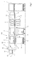
- FIG. 1 the basic structure of a sheet punching and embossing machine 100 for punching, breaking and depositing sheets of paper, cardboard and the like is shown.
- the punching and embossing machine 100 has a feeder 1, a punching station 2, a breaking station 3 and a boom 4, which are supported and enclosed by a common machine housing 5.
- the sheets 6 are separated by a feeder 1 from a stack, fed to the sheet transport system 7 and gripped by gripper bars of a gripper carriage 8 grippers at its front edge and intermittently in the sheet transport direction B through the various stations 2, 3 and 4 of the punching and embossing machine 100th pulled through.
- the sheet transport system has 7 more gripper carriage 8, so that multiple sheets 6 can be processed simultaneously in the various stations 2, 3 and 4.
- the punching station 2 consists of a lower crucible, a so-called. Subtable 9, and an upper crucible, a so-called. Obertisch 10.
- the upper table 10 is vertically reciprocably mounted and provided with punching and Rillmessern.
- the lower table 9 is fixedly mounted in the machine frame and provided with a counter plate to the punching and Rillmessern.
- the gripper carriage 8 transports the sheet 6 from the punching and embossing station 2 in the subsequent breaking station 3, which is equipped with breakout tools.
- the breaking station 3 the unwanted pieces of waste are pushed out of the sheet 6 downwards with the aid of the stripping tools, whereby the waste pieces 11 fall into a container-like carriage 12 inserted below the station.
- the sheet 6 passes into the boom 4, where the sheet 6 is either simply stored, or at the same time by a hub hegt hortrennwerkmaschinemaschine 50, a separation of the individual benefits.
- the boom 4 has a pneumatic sheet brake 41, which acts from below on a respective sheet 6, and a brake brush 42 which acts from above on a respective sheet 6.
- the pneumatic sheet brake 41 is optional for the invention set forth below. Both braking devices 41, 42 are positioned on the sheet trailing edge of the sheet 6.
- the boom 4 may also include a pallet 13, on which the individual sheets 6 are stacked in the form of a stack 14, so that after reaching a certain stack height, the pallets 14 are moved away with the piled sheets 6 from the field of punching and embossing machine 100 can.
- Fig. 2 shows a sheet brake device according to the prior art in a view.
- the device comprises two different brake elements: a pneumatic sheet brake 41, which is designed as a nozzle bar, and a brake brush with a plurality of bristles 42.
- the pneumatic sheet brake 41 is disposed below the sheet transport plane E and acts from below on a conveyed in the sheet transport direction B sheet. 6 by sucking it.
- the brake brushes 42 are arranged above the sheet transport plane E and act from on top of a sheet transported in the sheet transport direction B 6, by strip on this with light pressure.
- the brake brushes 42 are arranged on a transversely to the sheet transport direction B extending support 46, that the brake brushes 42 can be pivoted clocked by a pivoting movement D. By the pivoting movement D, the brake brushes 42 are lowered to an arc 6, if this is below the brake brushes 42 and then lifted off again.
- the pneumatic sheet brake 41 and the brake brush carrier 46 are mechanically coupled via a driving pin 44.
- the driving pin 44 is pressed by a spring against a groove 43 located in the carrier 46.
- the driving pin 44 is mounted vertically movable H in the pneumatic sheet brake 41.
- the groove 43 may be limited as shown at their ends. As a result, the support 46 is carried along by the driving pin 44 in and counter to the transport direction B. If the groove 43 is limited only at one of its last ends, then the carrier 46 is driven by the driving pin 44 only in one direction. The reset can then be done manually.
- the brake elements 41,42 can be moved automatically from the collision area. Due to the mechanical coupling of pneumatic sheet brake 41 and support 46, the support 46 is displaced when moving the pneumatic sheet brake 41. Once the pneumatic sheet brake 41 is in the correct position, the carrier 46 can be additionally displaced within the dimensions of the groove 43 in or against the sheet transport direction B. This additional displacement a2 is preferably done manually and allows a more accurate positioning of the brake brush 42 depending on the sheet size of the sheet 6 and allows the brake brush carrier 46 to move further out of the collision area with the top tools 50. As soon as the brake brushes 42 are also correctly positioned, the carrier 46 can be lowered into its working position in the direction H and, as in FIG Fig. 3 shown locked relative to the machine position 5.
- Fig. 3 shows a plan view of the inventive processing station 4 of the punching machine 100.
- a clamping device 45 is connected, through which the carrier 46 is locked to fixedly connected to the machine housing 5 strips.
- the pneumatic sheet brake 41 from the Fig. 1 and 2 which is optional for the invention, is in the embodiment according to Fig. 3 not used.
- positions are indicated where a reflector 61 attached to the clamping frame 51 of the upper tool 50 can be located.
- a sensor 60 which is aligned with the reflector 61, is mounted on the brake brush carrier 46.
- FIG. 4a is abutrennstation 4 with the sheet punching and / or embossing machine 100 shown in more detail:
- ATypetrenntechnikmaschine 52 is received by a clamping frame 51 and is liftable with this h.
- the blanking tool 52 cooperates with a
- aTypetrenngitter 53 which is fixedly disposed below the sheet transport plane E.
- a respective sheet 6 is transported in the sheet transport direction E between the Principaltrennwerkmaschinemaschine 52 and the respectivelytrenngitter 53 and stopped there.
- the braking of the sheet 6 is assisted by a pneumatic sheet brake 41, which is arranged below the sheet transport plane E and by a brake brush 42, 46, the bristles 42 press lightly on a respective sheet 6 and thus ensures that this one hand braked and the other Effective range of the pneumatic sheet brake 41 remains.
- a pneumatic sheet brake 41 instead of the pneumatic sheet brake 41 and a baffle can be used.
- the upper tool 50 in its top dead center. By its stroke h it is lowered so far that parts of theacitrenntechnikmaschines 52 pierce the sheet transport plane E and thus also a respective sheet 6. During this lifting movement h, however, the clamping frame 51 would collide with the brake brush carrier 46.
- a monitoring system which is already used when setting up the machine 100:
- a sensor 60 On the brake brush carrier 46, a sensor 60 is mounted, which in Direction of the clamping frame 51 is aligned and detects the position of the clamping frame 51.
- the clamping frame 51 is provided for this purpose with a reflective surface 61, which may be the surface of the clamping frame 51 or a specially applied reflector. As long as the brake brush carrier 46 with the sensor 60 is below the clamping frame 51, the presence of the clamping frame 51 is detected by the sensor 60.
- the sensor 60 is linked to a machine controller 15 via a data line or via a wireless data link.
- an evaluation can be made as to whether the position of the clamping frame 51 is compatible with the position of the brake brush and in particular the brake brush carrier 46.
- the positions of the brake brush 42, 46 and clamping frame 51 are incompatible and there would be a collision.
- the risk of collision can be indicated to the machine operator by the machine control 15 via an interface 63 or a warning device 62 by issuing a warning signal.
- the machine operator can be requested via the interface 63 of the machine control 15 to correct the position of the brake brush 42, 46.
- a correction movement a3 is required, ie the brake brush carrier 46 must be accordingly upstream, that is, against the sheet transport direction B, moved.
- FIG. 4a is additionally indicated in dashed lines an alternative position of the clamping frame 51. This is the maximum upstream position of the tenter at maximum size.
- the brake brush 42, 46 is shown in dashed lines in an alternative position. If the brake brush 42, 46 is in this alternative position, the brake brush 42, 46 can never collide with the tensioning frame 51 because the tensioning frame 51 can never be in this maximum upstream position range.
- an additional sensor 60 is provided to monitor this position range, which is a safe area. If the sensor 60 detects the presence of the brake brush 42, 46 in this safe area, there is no risk of collision and further detection by the other sensor 60, which is attached to the brake brush carrier 46, the position of the clamping frame 51 and a subsequent evaluation by the machine control is then no longer required.
- the second sensor 60 is also linked to the machine controller 15 via a data line or other data exchange connection.
- FIG. 4b the brake brush 42, 46 is shown in an alternative position.
- the position of the brake brush 42, 46 is located upstream than the position of the clamping frame 51.
- the attached to the brake brush holder 46 sensor 60 thus can not detect the clamping frame 51 and the evaluation by the machine control 15 shows that there is no risk of collision. So that the brushes 42 of the brake brush 42, 46 act as long as possible on a respective sheet 6, it is still possible to move the brake brush 42, 46 by a correction movement a3 in the sheet transport direction B. Only when the brake brush 42, 46 would be further moved in the direction of sheet transport B, would there again be a risk of collision and the sensor 60 would detect the presence of the clamping frame 51 above the sensor 60 and the machine control 15 to issue a warning signal to the operator.
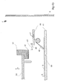
- FIG. 5 an alternative embodiment of the depaneling station 4 is shown. While the sensor 60 is also attached to the brake brush carrier 46, a reflector 61 projecting beyond the tensioning frame 51 has been attached to the tensioning frame 51. The sensor 60 is oriented upward in the direction of the reflector 61 and the clamping frame 51 and can detect them. If the sensor 60 detects the reflector 61, there is no risk of collision between the brake brush 42, 46 and the clamping frame 51 FIG. 5 In the case illustrated, the sensor 60 can not detect the reflector 61 and the evaluation by the machine controller 15 reveals that there is a risk of collision, which can be indicated to the machine operator by a corresponding warning signal.
- the brake brush 42, 46 In order to avoid an impending collision by the lifting movement h of the upper tool 50, the brake brush 42, 46 must undergo a correction movement a3. Once this is done, the sensor 60 detects the reflector 61 and the test by the machine control 15 reveals that the position of the brake brush 42, 46 and the clamping frame 51 are compatible with each other and there is no risk of collision.
- FIGS. 6a and 6b two further alternative embodiments of the depaneling station 4 are shown.
- the brake brush 42, 46 is positioned by a motor in or against the sheet transport direction B by an adjusting movement a2.
- the adjustment motor stands in a data exchange connection with the machine control 15. From the position of the adjusting motor, the machine control 15 can determine the position d2 of the brake brush holder 46.
- a sensor 60 is provided, which is also in communication with the machine control 15 and can transmit its measurement data to them.
- the sensor 60 is directed to the clamping frame 51, which may optionally be provided at its upstream end face with a reflector 61. By the sensor 60, the position d1 of the clamping frame 51 is detected and sent to the machine controller 15.
- a check can then be made as to whether the position d1 of the clamping frame 51 and the position d2 of the brake brush holder 46 are compatible with one another.
- Both are incompatible and it would lead to a collision of the clamping frame 51 with the brake brush carrier 46 as soon as the upper tool 50 executes its stroke h. Therefore, the brake brush 42, 46 against the sheet transport direction B must be moved further upstream.
- This correction movement a3 (not shown) is initiated by the adjusting motor, which in particular can be controlled accordingly by the machine control 15.
- the clamping frame 51 is also adjustable by an adjusting motor. Since both adjusting motors of brake brush 42, 46 and clamping frame 51 are in a data exchange connection with the machine control 15, the machine control 15 can determine the positions d1, d2 of brake brush 42, 46 and clamping frame 51 from the positions of the respective adjusting motors. If the positions d1, d2 are not compatible, the machine control 15 activates the adjustment motor of the brake brush 42, 46 so that it executes a correction movement a3 (not shown) and the brake-brush carrier 46 is moved out of the collision area.
Landscapes
- Engineering & Computer Science (AREA)
- Mechanical Engineering (AREA)
- Life Sciences & Earth Sciences (AREA)
- Forests & Forestry (AREA)
- Making Paper Articles (AREA)
- Braking Arrangements (AREA)
- Folding Of Thin Sheet-Like Materials, Special Discharging Devices, And Others (AREA)
Applications Claiming Priority (1)
| Application Number | Priority Date | Filing Date | Title |
|---|---|---|---|
| DE102013001778.5A DE102013001778A1 (de) | 2013-01-31 | 2013-01-31 | Überwachungsverfahren zur Kollisionsvermeidung einer Stanzmaschine mit Bremsbürste |
Publications (2)
| Publication Number | Publication Date |
|---|---|
| EP2762432A1 true EP2762432A1 (fr) | 2014-08-06 |
| EP2762432B1 EP2762432B1 (fr) | 2015-11-18 |
Family
ID=49726530
Family Applications (1)
| Application Number | Title | Priority Date | Filing Date |
|---|---|---|---|
| EP13195409.1A Active EP2762432B1 (fr) | 2013-01-31 | 2013-12-03 | Procédé de surveillance destiné à éviter la collision d'une poinçonneuse avec un balai de freinage |
Country Status (4)
| Country | Link |
|---|---|
| EP (1) | EP2762432B1 (fr) |
| CN (1) | CN103964250B (fr) |
| DE (1) | DE102013001778A1 (fr) |
| ES (1) | ES2555471T3 (fr) |
Cited By (1)
| Publication number | Priority date | Publication date | Assignee | Title |
|---|---|---|---|---|
| IT201800004107A1 (it) * | 2018-03-29 | 2019-09-29 | Orox S R L | Metodo di verifica di taglio di almeno un foglio di tessuto, in particolare un materasso di tessuti, e relativo sistema di taglio |
Families Citing this family (2)
| Publication number | Priority date | Publication date | Assignee | Title |
|---|---|---|---|---|
| CN108189118B (zh) * | 2017-12-30 | 2020-06-23 | 佛山锋顺机械科技有限公司 | 一种切割机的送料装置及切割机 |
| CN113119228A (zh) * | 2021-04-23 | 2021-07-16 | 包头职业技术学院 | 一种高速自动模切机 |
Citations (4)
| Publication number | Priority date | Publication date | Assignee | Title |
|---|---|---|---|---|
| DE3044083A1 (de) | 1980-11-24 | 1982-09-09 | Wupa-Maschinenfabrik GmbH, 4057 Brüggen | Stanzeinrichtung |
| US5599012A (en) * | 1994-05-11 | 1997-02-04 | Bobst Sa | Decelerating system for decelerating the movement of sheets into the delivery station of a sheet fed press |
| DE102008010985A1 (de) | 2008-02-25 | 2009-08-27 | Heidelberger Druckmaschinen Ag | Bogenbremseinrichtung |
| US7658378B2 (en) | 2007-01-15 | 2010-02-09 | Heidelberger Druckmaschinen Ag | Apparatus and method for aligning sheet stacks and sheet processing machine having the apparatus |
Family Cites Families (6)
| Publication number | Priority date | Publication date | Assignee | Title |
|---|---|---|---|---|
| IT243960Y1 (it) * | 1998-04-23 | 2002-03-06 | Fotoba Internat S A S Di Pietr | Dispositivo automatico di taglio in squadra di carta ed altrisupporti grafici e fotografici |
| US6418824B1 (en) * | 2000-03-03 | 2002-07-16 | Pcps Limited Partnership | Two stage punch press actuator with output drive shaft position sensing |
| TWI241241B (en) * | 2003-10-13 | 2005-10-11 | Bobst Sa | Blank diecutting machine |
| DE102007014315A1 (de) * | 2006-07-26 | 2008-01-31 | Heidelberger Druckmaschinen Ag | Verfahren zum Stanzen und Bogenstanz- und -prägemaschine |
| TWI396627B (zh) * | 2008-12-05 | 2013-05-21 | Bobst Sa | 在用於處理平板元件之機器中的校準方法 |
| JP5404209B2 (ja) * | 2009-06-29 | 2014-01-29 | キヤノン株式会社 | シート搬送装置及び画像形成装置 |
-
2013
- 2013-01-31 DE DE102013001778.5A patent/DE102013001778A1/de not_active Withdrawn
- 2013-12-03 ES ES13195409.1T patent/ES2555471T3/es active Active
- 2013-12-03 EP EP13195409.1A patent/EP2762432B1/fr active Active
-
2014
- 2014-01-29 CN CN201410043682.4A patent/CN103964250B/zh active Active
Patent Citations (5)
| Publication number | Priority date | Publication date | Assignee | Title |
|---|---|---|---|---|
| DE3044083A1 (de) | 1980-11-24 | 1982-09-09 | Wupa-Maschinenfabrik GmbH, 4057 Brüggen | Stanzeinrichtung |
| US5599012A (en) * | 1994-05-11 | 1997-02-04 | Bobst Sa | Decelerating system for decelerating the movement of sheets into the delivery station of a sheet fed press |
| US7658378B2 (en) | 2007-01-15 | 2010-02-09 | Heidelberger Druckmaschinen Ag | Apparatus and method for aligning sheet stacks and sheet processing machine having the apparatus |
| DE102008010985A1 (de) | 2008-02-25 | 2009-08-27 | Heidelberger Druckmaschinen Ag | Bogenbremseinrichtung |
| US8079587B2 (en) | 2008-02-25 | 2011-12-20 | Heidelberger Druckmaschinen Aktiengesellschaft | Sheet braking mechanism |
Cited By (2)
| Publication number | Priority date | Publication date | Assignee | Title |
|---|---|---|---|---|
| IT201800004107A1 (it) * | 2018-03-29 | 2019-09-29 | Orox S R L | Metodo di verifica di taglio di almeno un foglio di tessuto, in particolare un materasso di tessuti, e relativo sistema di taglio |
| WO2019185440A1 (fr) * | 2018-03-29 | 2019-10-03 | Orox S.R.L. | Procédé de vérification de coupe pour au moins une feuille de tissu, en particulier un matelas de tissus, et système de coupe associé |
Also Published As
| Publication number | Publication date |
|---|---|
| DE102013001778A1 (de) | 2014-07-31 |
| ES2555471T3 (es) | 2016-01-04 |
| CN103964250A (zh) | 2014-08-06 |
| CN103964250B (zh) | 2017-03-08 |
| EP2762432B1 (fr) | 2015-11-18 |
Similar Documents
| Publication | Publication Date | Title |
|---|---|---|
| EP1882566B1 (fr) | Presse de découpage et de rainurage ayant un alignement de repère et procédé de mise en oeuvre d'une telle presse | |
| EP2407402B1 (fr) | Procédé et dispositif destinés à positionner des feuilles | |
| EP1882657B1 (fr) | Système de freinage pour feuilles | |
| EP1914049B1 (fr) | Presse à platines | |
| EP2452790B1 (fr) | Station de traitement pour une estampilleuse et procédé de sortie de feuilles d'ébauche | |
| EP2754541B1 (fr) | Procédé de réglage de la force de compression d'une machine a poiçonner et estamper | |
| EP2098469B1 (fr) | Procédé de mesure de la position de feuilles et d'alignement de feuilles | |
| EP2722141B1 (fr) | Dispositif pour une presse de découpe à plat et procédé d'acheminement d'une bande de matière à imprimer | |
| DE102007020496A1 (de) | Bogenstanz- und -prägemaschine | |
| EP2397285B1 (fr) | Station d'estampage et/ou d'embossage pour machine à estamper des cintres | |
| EP2399715A1 (fr) | Station de dépôt et de séparation des usages pour une machine à estamper des cintres | |
| EP2093176B1 (fr) | Dispositif de freinage de feuilles | |
| DE102011118283A1 (de) | Bearbeitungsstation einer Bogenstanzmaschine mit Stellmotor | |
| EP2762432B1 (fr) | Procédé de surveillance destiné à éviter la collision d'une poinçonneuse avec un balai de freinage | |
| EP2653420B1 (fr) | Procédé de transfert de feuille et machine à découper à l'emporte-pièce dotée d'un système de transport à pince | |
| EP2014589A2 (fr) | Presse de découpage et de cannelage et procédé destiné à l'orientation des feuilles | |
| EP2572843B1 (fr) | Procédé d'alignement d'un outil d'estampillage et station de découpage avec plaque de recouvrement pouvant être aspirée | |
| DE102011118905B4 (de) | Bearbeitungsstation für eine Stanzmaschine | |
| DE202007012356U1 (de) | Hinterkantenbremssystem | |
| EP2479011B1 (fr) | Unité d'adaptateur pour la réception d'outils d'estampillage | |
| DE102006049112A1 (de) | Flachbrett-Bogenstanzmaschine | |
| DE102013006348A1 (de) | Oberwerkzeug, Bearbeitungsstation und Verfahren zum Ausbrechen | |
| EP1925387A1 (fr) | Machine à estamper de cintres à banc plat | |
| EP2216278A2 (fr) | Procédé de transmission de feuilles |
Legal Events
| Date | Code | Title | Description |
|---|---|---|---|
| PUAI | Public reference made under article 153(3) epc to a published international application that has entered the european phase |
Free format text: ORIGINAL CODE: 0009012 |
|
| 17P | Request for examination filed |
Effective date: 20131203 |
|
| AK | Designated contracting states |
Kind code of ref document: A1 Designated state(s): AL AT BE BG CH CY CZ DE DK EE ES FI FR GB GR HR HU IE IS IT LI LT LU LV MC MK MT NL NO PL PT RO RS SE SI SK SM TR |
|
| AX | Request for extension of the european patent |
Extension state: BA ME |
|
| R17P | Request for examination filed (corrected) |
Effective date: 20150206 |
|
| RBV | Designated contracting states (corrected) |
Designated state(s): AL AT BE BG CH CY CZ DE DK EE ES FI FR GB GR HR HU IE IS IT LI LT LU LV MC MK MT NL NO PL PT RO RS SE SI SK SM TR |
|
| RAP1 | Party data changed (applicant data changed or rights of an application transferred) |
Owner name: MASTERWORK MACHINERY CO., LTD. |
|
| GRAP | Despatch of communication of intention to grant a patent |
Free format text: ORIGINAL CODE: EPIDOSNIGR1 |
|
| RIC1 | Information provided on ipc code assigned before grant |
Ipc: B65H 29/68 20060101AFI20150430BHEP Ipc: B26F 1/40 20060101ALN20150430BHEP Ipc: B26D 7/22 20060101ALI20150430BHEP Ipc: B65H 29/04 20060101ALI20150430BHEP Ipc: B26D 7/06 20060101ALN20150430BHEP |
|
| INTG | Intention to grant announced |
Effective date: 20150519 |
|
| GRAS | Grant fee paid |
Free format text: ORIGINAL CODE: EPIDOSNIGR3 |
|
| GRAA | (expected) grant |
Free format text: ORIGINAL CODE: 0009210 |
|
| AK | Designated contracting states |
Kind code of ref document: B1 Designated state(s): AL AT BE BG CH CY CZ DE DK EE ES FI FR GB GR HR HU IE IS IT LI LT LU LV MC MK MT NL NO PL PT RO RS SE SI SK SM TR |
|
| REG | Reference to a national code |
Ref country code: GB Ref legal event code: FG4D Free format text: NOT ENGLISH |
|
| REG | Reference to a national code |
Ref country code: CH Ref legal event code: EP |
|
| REG | Reference to a national code |
Ref country code: AT Ref legal event code: REF Ref document number: 761443 Country of ref document: AT Kind code of ref document: T Effective date: 20151215 |
|
| REG | Reference to a national code |
Ref country code: IE Ref legal event code: FG4D Free format text: LANGUAGE OF EP DOCUMENT: GERMAN |
|
| REG | Reference to a national code |
Ref country code: ES Ref legal event code: FG2A Ref document number: 2555471 Country of ref document: ES Kind code of ref document: T3 Effective date: 20160104 |
|
| REG | Reference to a national code |
Ref country code: DE Ref legal event code: R096 Ref document number: 502013001508 Country of ref document: DE |
|
| REG | Reference to a national code |
Ref country code: NL Ref legal event code: MP Effective date: 20160218 |
|
| REG | Reference to a national code |
Ref country code: LT Ref legal event code: MG4D |
|
| REG | Reference to a national code |
Ref country code: FR Ref legal event code: PLFP Year of fee payment: 4 Ref country code: FR Ref legal event code: PLFP Year of fee payment: 3 |
|
| PG25 | Lapsed in a contracting state [announced via postgrant information from national office to epo] |
Ref country code: LT Free format text: LAPSE BECAUSE OF FAILURE TO SUBMIT A TRANSLATION OF THE DESCRIPTION OR TO PAY THE FEE WITHIN THE PRESCRIBED TIME-LIMIT Effective date: 20151118 Ref country code: IS Free format text: LAPSE BECAUSE OF FAILURE TO SUBMIT A TRANSLATION OF THE DESCRIPTION OR TO PAY THE FEE WITHIN THE PRESCRIBED TIME-LIMIT Effective date: 20160318 Ref country code: NL Free format text: LAPSE BECAUSE OF FAILURE TO SUBMIT A TRANSLATION OF THE DESCRIPTION OR TO PAY THE FEE WITHIN THE PRESCRIBED TIME-LIMIT Effective date: 20151118 Ref country code: NO Free format text: LAPSE BECAUSE OF FAILURE TO SUBMIT A TRANSLATION OF THE DESCRIPTION OR TO PAY THE FEE WITHIN THE PRESCRIBED TIME-LIMIT Effective date: 20160218 Ref country code: HR Free format text: LAPSE BECAUSE OF FAILURE TO SUBMIT A TRANSLATION OF THE DESCRIPTION OR TO PAY THE FEE WITHIN THE PRESCRIBED TIME-LIMIT Effective date: 20151118 |
|
| PG25 | Lapsed in a contracting state [announced via postgrant information from national office to epo] |
Ref country code: BE Free format text: LAPSE BECAUSE OF NON-PAYMENT OF DUE FEES Effective date: 20151231 Ref country code: GR Free format text: LAPSE BECAUSE OF FAILURE TO SUBMIT A TRANSLATION OF THE DESCRIPTION OR TO PAY THE FEE WITHIN THE PRESCRIBED TIME-LIMIT Effective date: 20160219 Ref country code: PT Free format text: LAPSE BECAUSE OF FAILURE TO SUBMIT A TRANSLATION OF THE DESCRIPTION OR TO PAY THE FEE WITHIN THE PRESCRIBED TIME-LIMIT Effective date: 20160318 Ref country code: FI Free format text: LAPSE BECAUSE OF FAILURE TO SUBMIT A TRANSLATION OF THE DESCRIPTION OR TO PAY THE FEE WITHIN THE PRESCRIBED TIME-LIMIT Effective date: 20151118 Ref country code: RS Free format text: LAPSE BECAUSE OF FAILURE TO SUBMIT A TRANSLATION OF THE DESCRIPTION OR TO PAY THE FEE WITHIN THE PRESCRIBED TIME-LIMIT Effective date: 20151118 Ref country code: PL Free format text: LAPSE BECAUSE OF FAILURE TO SUBMIT A TRANSLATION OF THE DESCRIPTION OR TO PAY THE FEE WITHIN THE PRESCRIBED TIME-LIMIT Effective date: 20151118 Ref country code: SE Free format text: LAPSE BECAUSE OF FAILURE TO SUBMIT A TRANSLATION OF THE DESCRIPTION OR TO PAY THE FEE WITHIN THE PRESCRIBED TIME-LIMIT Effective date: 20151118 Ref country code: LV Free format text: LAPSE BECAUSE OF FAILURE TO SUBMIT A TRANSLATION OF THE DESCRIPTION OR TO PAY THE FEE WITHIN THE PRESCRIBED TIME-LIMIT Effective date: 20151118 |
|
| PG25 | Lapsed in a contracting state [announced via postgrant information from national office to epo] |
Ref country code: CZ Free format text: LAPSE BECAUSE OF FAILURE TO SUBMIT A TRANSLATION OF THE DESCRIPTION OR TO PAY THE FEE WITHIN THE PRESCRIBED TIME-LIMIT Effective date: 20151118 |
|
| REG | Reference to a national code |
Ref country code: DE Ref legal event code: R097 Ref document number: 502013001508 Country of ref document: DE |
|
| PG25 | Lapsed in a contracting state [announced via postgrant information from national office to epo] |
Ref country code: SM Free format text: LAPSE BECAUSE OF FAILURE TO SUBMIT A TRANSLATION OF THE DESCRIPTION OR TO PAY THE FEE WITHIN THE PRESCRIBED TIME-LIMIT Effective date: 20151118 Ref country code: SK Free format text: LAPSE BECAUSE OF FAILURE TO SUBMIT A TRANSLATION OF THE DESCRIPTION OR TO PAY THE FEE WITHIN THE PRESCRIBED TIME-LIMIT Effective date: 20151118 Ref country code: RO Free format text: LAPSE BECAUSE OF FAILURE TO SUBMIT A TRANSLATION OF THE DESCRIPTION OR TO PAY THE FEE WITHIN THE PRESCRIBED TIME-LIMIT Effective date: 20151118 Ref country code: EE Free format text: LAPSE BECAUSE OF FAILURE TO SUBMIT A TRANSLATION OF THE DESCRIPTION OR TO PAY THE FEE WITHIN THE PRESCRIBED TIME-LIMIT Effective date: 20151118 Ref country code: DK Free format text: LAPSE BECAUSE OF FAILURE TO SUBMIT A TRANSLATION OF THE DESCRIPTION OR TO PAY THE FEE WITHIN THE PRESCRIBED TIME-LIMIT Effective date: 20151118 |
|
| REG | Reference to a national code |
Ref country code: IE Ref legal event code: MM4A |
|
| PLBE | No opposition filed within time limit |
Free format text: ORIGINAL CODE: 0009261 |
|
| STAA | Information on the status of an ep patent application or granted ep patent |
Free format text: STATUS: NO OPPOSITION FILED WITHIN TIME LIMIT |
|
| PG25 | Lapsed in a contracting state [announced via postgrant information from national office to epo] |
Ref country code: MC Free format text: LAPSE BECAUSE OF FAILURE TO SUBMIT A TRANSLATION OF THE DESCRIPTION OR TO PAY THE FEE WITHIN THE PRESCRIBED TIME-LIMIT Effective date: 20151118 |
|
| 26N | No opposition filed |
Effective date: 20160819 |
|
| PG25 | Lapsed in a contracting state [announced via postgrant information from national office to epo] |
Ref country code: IE Free format text: LAPSE BECAUSE OF NON-PAYMENT OF DUE FEES Effective date: 20151203 |
|
| PG25 | Lapsed in a contracting state [announced via postgrant information from national office to epo] |
Ref country code: SI Free format text: LAPSE BECAUSE OF FAILURE TO SUBMIT A TRANSLATION OF THE DESCRIPTION OR TO PAY THE FEE WITHIN THE PRESCRIBED TIME-LIMIT Effective date: 20151118 |
|
| REG | Reference to a national code |
Ref country code: FR Ref legal event code: PLFP Year of fee payment: 4 |
|
| PG25 | Lapsed in a contracting state [announced via postgrant information from national office to epo] |
Ref country code: BG Free format text: LAPSE BECAUSE OF FAILURE TO SUBMIT A TRANSLATION OF THE DESCRIPTION OR TO PAY THE FEE WITHIN THE PRESCRIBED TIME-LIMIT Effective date: 20151118 Ref country code: HU Free format text: LAPSE BECAUSE OF FAILURE TO SUBMIT A TRANSLATION OF THE DESCRIPTION OR TO PAY THE FEE WITHIN THE PRESCRIBED TIME-LIMIT; INVALID AB INITIO Effective date: 20131203 |
|
| PG25 | Lapsed in a contracting state [announced via postgrant information from national office to epo] |
Ref country code: CY Free format text: LAPSE BECAUSE OF FAILURE TO SUBMIT A TRANSLATION OF THE DESCRIPTION OR TO PAY THE FEE WITHIN THE PRESCRIBED TIME-LIMIT Effective date: 20151118 |
|
| PG25 | Lapsed in a contracting state [announced via postgrant information from national office to epo] |
Ref country code: MT Free format text: LAPSE BECAUSE OF FAILURE TO SUBMIT A TRANSLATION OF THE DESCRIPTION OR TO PAY THE FEE WITHIN THE PRESCRIBED TIME-LIMIT Effective date: 20151118 |
|
| PG25 | Lapsed in a contracting state [announced via postgrant information from national office to epo] |
Ref country code: LU Free format text: LAPSE BECAUSE OF NON-PAYMENT OF DUE FEES Effective date: 20151203 |
|
| REG | Reference to a national code |
Ref country code: FR Ref legal event code: PLFP Year of fee payment: 5 |
|
| PG25 | Lapsed in a contracting state [announced via postgrant information from national office to epo] |
Ref country code: MK Free format text: LAPSE BECAUSE OF FAILURE TO SUBMIT A TRANSLATION OF THE DESCRIPTION OR TO PAY THE FEE WITHIN THE PRESCRIBED TIME-LIMIT Effective date: 20151118 |
|
| PG25 | Lapsed in a contracting state [announced via postgrant information from national office to epo] |
Ref country code: AL Free format text: LAPSE BECAUSE OF FAILURE TO SUBMIT A TRANSLATION OF THE DESCRIPTION OR TO PAY THE FEE WITHIN THE PRESCRIBED TIME-LIMIT Effective date: 20151118 Ref country code: TR Free format text: LAPSE BECAUSE OF FAILURE TO SUBMIT A TRANSLATION OF THE DESCRIPTION OR TO PAY THE FEE WITHIN THE PRESCRIBED TIME-LIMIT Effective date: 20151118 |
|
| REG | Reference to a national code |
Ref country code: AT Ref legal event code: MM01 Ref document number: 761443 Country of ref document: AT Kind code of ref document: T Effective date: 20181203 |
|
| PG25 | Lapsed in a contracting state [announced via postgrant information from national office to epo] |
Ref country code: AT Free format text: LAPSE BECAUSE OF NON-PAYMENT OF DUE FEES Effective date: 20181203 |
|
| PGFP | Annual fee paid to national office [announced via postgrant information from national office to epo] |
Ref country code: FR Payment date: 20211217 Year of fee payment: 9 |
|
| PGFP | Annual fee paid to national office [announced via postgrant information from national office to epo] |
Ref country code: IT Payment date: 20211231 Year of fee payment: 9 Ref country code: ES Payment date: 20220103 Year of fee payment: 9 |
|
| REG | Reference to a national code |
Ref country code: CH Ref legal event code: PL |
|
| PG25 | Lapsed in a contracting state [announced via postgrant information from national office to epo] |
Ref country code: LI Free format text: LAPSE BECAUSE OF NON-PAYMENT OF DUE FEES Effective date: 20221231 Ref country code: CH Free format text: LAPSE BECAUSE OF NON-PAYMENT OF DUE FEES Effective date: 20221231 |
|
| PGRI | Patent reinstated in contracting state [announced from national office to epo] |
Ref country code: LI Effective date: 20230818 Ref country code: CH Effective date: 20230818 |
|
| PG25 | Lapsed in a contracting state [announced via postgrant information from national office to epo] |
Ref country code: FR Free format text: LAPSE BECAUSE OF NON-PAYMENT OF DUE FEES Effective date: 20221231 |
|
| PGFP | Annual fee paid to national office [announced via postgrant information from national office to epo] |
Ref country code: GB Payment date: 20231219 Year of fee payment: 11 |
|
| REG | Reference to a national code |
Ref country code: ES Ref legal event code: FD2A Effective date: 20240126 |
|
| PG25 | Lapsed in a contracting state [announced via postgrant information from national office to epo] |
Ref country code: IT Free format text: LAPSE BECAUSE OF NON-PAYMENT OF DUE FEES Effective date: 20221203 |
|
| PG25 | Lapsed in a contracting state [announced via postgrant information from national office to epo] |
Ref country code: ES Free format text: LAPSE BECAUSE OF NON-PAYMENT OF DUE FEES Effective date: 20221204 |
|
| PG25 | Lapsed in a contracting state [announced via postgrant information from national office to epo] |
Ref country code: ES Free format text: LAPSE BECAUSE OF NON-PAYMENT OF DUE FEES Effective date: 20221204 |
|
| PGFP | Annual fee paid to national office [announced via postgrant information from national office to epo] |
Ref country code: DE Payment date: 20231227 Year of fee payment: 11 Ref country code: CH Payment date: 20240101 Year of fee payment: 11 |
|
| REG | Reference to a national code |
Ref country code: DE Ref legal event code: R119 Ref document number: 502013001508 Country of ref document: DE |
|
| REG | Reference to a national code |
Ref country code: CH Ref legal event code: PL |
|
| GBPC | Gb: european patent ceased through non-payment of renewal fee |
Effective date: 20241203 |
|
| PG25 | Lapsed in a contracting state [announced via postgrant information from national office to epo] |
Ref country code: DE Free format text: LAPSE BECAUSE OF NON-PAYMENT OF DUE FEES Effective date: 20250701 |
|
| PG25 | Lapsed in a contracting state [announced via postgrant information from national office to epo] |
Ref country code: GB Free format text: LAPSE BECAUSE OF NON-PAYMENT OF DUE FEES Effective date: 20241203 |
|
| PG25 | Lapsed in a contracting state [announced via postgrant information from national office to epo] |
Ref country code: CH Free format text: LAPSE BECAUSE OF NON-PAYMENT OF DUE FEES Effective date: 20241231 |